[go: up one dir, main page]

CN113739683A - Zero calibration device, striker with zero calibration device, zero calibration method and striking method - Google Patents

Zero calibration device, striker with zero calibration device, zero calibration method and striking method Download PDF

Info

Publication number
CN113739683A
CN113739683A CN202111310674.8A CN202111310674A CN113739683A CN 113739683 A CN113739683 A CN 113739683A CN 202111310674 A CN202111310674 A CN 202111310674A CN 113739683 A CN113739683 A CN 113739683A
Authority
CN
China
Prior art keywords
conductor
striking
lever
contact
zero calibration
Prior art date
Legal status (The legal status is an assumption and is not a legal conclusion. Google has not performed a legal analysis and makes no representation as to the accuracy of the status listed.)
Granted
Application number
CN202111310674.8A
Other languages
Chinese (zh)
Other versions
CN113739683B (en
Inventor
邱勇
荆华
阳方义
潘雅楠
Current Assignee (The listed assignees may be inaccurate. Google has not performed a legal analysis and makes no representation or warranty as to the accuracy of the list.)
Shenzhen Ruiwode Life Technology Co ltd
Original Assignee
Rwd Life Science Co ltd
Priority date (The priority date is an assumption and is not a legal conclusion. Google has not performed a legal analysis and makes no representation as to the accuracy of the date listed.)
Filing date
Publication date
Application filed by Rwd Life Science Co ltd filed Critical Rwd Life Science Co ltd
Priority to CN202111310674.8A priority Critical patent/CN113739683B/en
Publication of CN113739683A publication Critical patent/CN113739683A/en
Application granted granted Critical
Publication of CN113739683B publication Critical patent/CN113739683B/en
Active legal-status Critical Current
Anticipated expiration legal-status Critical

Links

Images

Classifications

    • GPHYSICS
    • G01MEASURING; TESTING
    • G01BMEASURING LENGTH, THICKNESS OR SIMILAR LINEAR DIMENSIONS; MEASURING ANGLES; MEASURING AREAS; MEASURING IRREGULARITIES OF SURFACES OR CONTOURS
    • G01B7/00Measuring arrangements characterised by the use of electric or magnetic techniques
    • G01B7/003Measuring arrangements characterised by the use of electric or magnetic techniques for measuring position, not involving coordinate determination
    • AHUMAN NECESSITIES
    • A61MEDICAL OR VETERINARY SCIENCE; HYGIENE
    • A61DVETERINARY INSTRUMENTS, IMPLEMENTS, TOOLS, OR METHODS
    • A61D1/00Surgical instruments for veterinary use

Landscapes

  • Health & Medical Sciences (AREA)
  • Veterinary Medicine (AREA)
  • Life Sciences & Earth Sciences (AREA)
  • Zoology (AREA)
  • Engineering & Computer Science (AREA)
  • Wood Science & Technology (AREA)
  • Surgery (AREA)
  • Animal Behavior & Ethology (AREA)
  • General Health & Medical Sciences (AREA)
  • Public Health (AREA)
  • Physics & Mathematics (AREA)
  • General Physics & Mathematics (AREA)
  • Catching Or Destruction (AREA)

Abstract

本发明提供一种校零装置,包括:支架;通过旋转轴与支架连接的杠杆;设置于杠杆的第二端的触头;设置于杠杆的第一端的第一导体;以及固定于支架、与支架绝缘的第二导体;支架和第二导体分别与电源连接,当触头到达打击位置受力时,第一导体和第二导体断开连接。本发明在支架上设置杠杆,杠杆的一端设置用于接触打击位置的触头,杠杆的另一端设置与触头形成杠杆平衡的第一导体,第一导体与支架上的第二导体接触,构成支架、杠杆、第一导体、第二导体和电源的电回路,当触头到达打击位置受力时,通过电路通断和杠杆力学相结合的方式定位打击位置,避免了打击位置覆盖有组织液时校零不准的问题,保证建立动物损伤模型的准确性。

Figure 202111310674

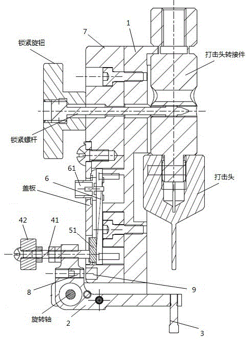
The invention provides a zero calibration device, comprising: a bracket; a lever connected with the bracket through a rotating shaft; a contact arranged at the second end of the lever; a first conductor arranged at the first end of the lever; The second conductor insulated by the bracket; the bracket and the second conductor are respectively connected with the power supply, and when the contact reaches the striking position and is stressed, the first conductor and the second conductor are disconnected. In the present invention, a lever is arranged on the bracket, one end of the lever is arranged with a contact for contacting the striking position, the other end of the lever is arranged with a first conductor that forms a lever balance with the contact, and the first conductor is in contact with the second conductor on the bracket. The electrical circuit of the bracket, lever, first conductor, second conductor and power supply, when the contact reaches the striking position and is stressed, the striking position is positioned by the combination of circuit on-off and lever mechanics, avoiding the situation when the striking position is covered with tissue fluid The problem of inaccurate calibration ensures the accuracy of establishing animal injury models.

Figure 202111310674

Description

Zero calibration device, striker with zero calibration device, zero calibration method and striking method
Technical Field
The invention relates to the technical field of scientific research experimental equipment, in particular to a zero calibration device, a striking device with the zero calibration device, a zero calibration method and a striking method.
Background
Traumatic brain injury and spinal cord injury are the most common diseases in neurosurgery and are the main causes of disability and death in trauma patients. The change of motor, sensory and autonomic nerve functions of trauma patients after traumatic brain injury and spinal cord injury is researched, the specific mechanism of various dysfunctions caused by the nervous system injury of the trauma patients is researched, the protection and treatment of the traumatic brain injury and the spinal cord injury are facilitated, and the survival rate and the survival quality of the trauma patients are facilitated to be improved. The method is characterized in that various animal injury models which are convenient for observing and applying intervention factors, have the advantages of grading, good controllability and good reproducibility and accord with the characteristics of human traumatic brain injury and spinal cord injury are established, and the method is a research hotspot of traumatic brain injury and spinal cord injury. At present, the mainstream equipment for establishing an animal injury model is a precision impactor, so that a low-speed craniocerebral injury model can be realized, and a spinal cord injury model can also be realized. When the precise impactor is used for establishing a low-speed craniocerebral injury model or a spinal cord injury model, the positioning accuracy of the precise impactor is particularly critical.
The device for ensuring the positioning accuracy is a zero calibration device, which can also be called a percussion instrument zero calibration device. The zero calibration technology in the prior art mainly comprises a laser ranging technology. The zero calibration device adopting the laser ranging technology judges the distance from the striking head to the striking position through the reflection of light, but is limited in that the striking position is probabilistically covered with tissue fluid to influence the judgment, so that the zero calibration is inaccurate.
Disclosure of Invention
The embodiment of the invention provides a zero calibration device, aiming at solving the problem of inaccurate zero calibration when a striking position is covered with tissue fluid in the prior art.
In a first aspect, a zero calibration apparatus is provided, including:
a support (1);
a lever (2) connected to the bracket through a rotation shaft;
a contact (3) arranged at the second end of the lever (2);
a first conductor (4) disposed at a first end of the lever (2); and
a second conductor (5) fixed to the support (1) and insulated from the support (1);
the bracket (1) and the second conductor (5) are respectively connected with a power supply, and when the contact (3) reaches a striking position and is stressed, the first conductor (4) and the second conductor (5) are disconnected.
In a second aspect, there is provided a striker comprising a power source, a striker body and a zero calibration device as described above; the beater body is connected with a power supply, and the zero calibration device is arranged on the beater body.
In a third aspect, a zero calibration method is provided for performing zero calibration by a percussion device as described above.
In a fourth aspect, there is provided a striking method including:
obtaining a striking position by the zeroing method as described above;
after the zero calibration device is taken down, the distance between the striking head and the contact (3) is compensated;
and striking the striking position by the striking head according to the striking parameters.
According to the embodiment of the invention, the lever is arranged on the bracket, one end of the lever is provided with the contact used for contacting the striking position, the other end of the lever is provided with the first conductor forming lever balance with the contact, the first conductor is contacted with the second conductor on the bracket to form an electric loop of the bracket, the lever, the first conductor, the second conductor and the power supply, when the contact reaches the striking position and is stressed, the lever balance is damaged, the first conductor is disconnected with the second conductor, the striking position is positioned in a mode of combining circuit on-off and lever mechanics, the problem of inaccurate zero calibration when the striking position is covered with tissue fluid is avoided, and the accuracy of establishing an animal injury model is ensured.
Drawings
The foregoing and/or additional aspects and advantages of the present invention will become apparent and readily appreciated from the following description of the embodiments, taken in conjunction with the accompanying drawings of which:
FIG. 1 is a schematic view of a striker;
FIG. 2 is a schematic view of the striking position covered with interstitial fluid;
fig. 3 is an exploded view of a zero calibration device provided in an adaptor of a striking head according to an embodiment of the present invention;
FIG. 4 is a cross-sectional view taken along section line A1A2 in FIG. 3;
FIG. 5 is a schematic diagram of an electrical circuit provided in accordance with an embodiment of the present invention;
fig. 6 is a front view of a PCB board according to a first embodiment of the present invention;
FIG. 7 is a cross-sectional view taken along section line B1B2 in FIG. 6;
FIG. 8 is a flowchart of a zeroing method according to a third embodiment of the present invention;
fig. 9 is a flowchart of a striking method according to a fourth embodiment of the present invention.
Detailed Description
Reference will now be made in detail to embodiments of the present invention, examples of which are illustrated in the accompanying drawings, wherein like or similar reference numerals refer to the same or similar modules or modules having the same or similar functionality throughout. The embodiments described below with reference to the accompanying drawings are illustrative only for the purpose of explaining the present invention, and are not to be construed as limiting the present invention.
Fig. 1 is a schematic view of a percussion device, and a zero calibration device is arranged on a percussion device body. When an animal injury model is established, an experimental animal (not shown in the figure) is fixed below the zero calibration device, and the zero calibration device moves downwards to position the striking position. And after the striking position is positioned, recording the striking position, and finishing zero calibration. The zero calibration device is taken down, and the striking head (not shown in the figure) is controlled to strike the striking position according to the striking parameters. Fig. 2 is a schematic view of the striking position covered with interstitial fluid. If the actual striking position is covered with the tissue fluid, the zero calibration device in the prior art stops zero calibration when being positioned at the position of the tissue fluid, and the position of the tissue fluid is taken as the striking position, so that the animal injury model established by striking is inaccurate.
According to the embodiment of the invention, the lever is arranged on the bracket, one end of the lever is provided with the contact used for contacting the striking position, the other end of the lever is provided with the first conductor forming lever balance with the contact, the first conductor is contacted with the second conductor on the bracket to form an electric loop of the bracket, the lever, the first conductor, the second conductor and the power supply, when the contact reaches the striking position and is stressed, the lever balance is damaged, the first conductor is disconnected with the second conductor, the striking position is positioned in a mode of combining circuit on-off and lever mechanics, the problem of inaccurate zero calibration when the striking position is covered with tissue fluid is avoided, and the accuracy of establishing an animal injury model is ensured.
Example one
Fig. 3 is an exploded view of a zero calibration device provided in an adaptor of a striking head according to an embodiment of the present invention. Fig. 4 is a cross-sectional view of fig. 3 taken along section line A1a 2. As shown in fig. 3 and 4, the zero calibration device includes a holder 1, a lever 2, a contact 3, a first conductor 4, a second conductor 5, and an insulating plate 7. The bracket 1 plays a supporting role for other parts of the zero calibration device. When the zero calibration is finished, the zero calibration device can be locked on the striking head adapter through the bracket 1. The lever 2 is connected to the bracket 1 through a rotation shaft. The bracket 1 and the lever 2 are both conductors. Weights are placed at both ends of the lever 2. A first conductor 4 is arranged at a first end of the lever 2, and a contact 3 is arranged at a second end of the lever 2, so that lever balance is formed. Optionally, the distance of the first conductor 4 to the rotation axis or the gravity of the first conductor 4 is adjustable, so that the moment on the side of the first conductor 4 is adjustable; the distance of contact 3 from the axis of rotation or the weight of contact 3 is adjustable so that the moment on one side of contact 3 is adjustable. The zero calibration contact 3 is used to contact the striking position. The second conductor 5 is fixed to the bracket 1 opposite to the first conductor 4. An insulating plate 7 is arranged between the holder 1 and the second conductor 5. The holder 1 and the second conductor 5 are each connected to a power supply (not shown in the figure). When the contact 3 is not in contact with the striking position and the lever 2 is in a lever balance state, the first conductor 4 and the second conductor 5 are in contact to form an electric loop of the bracket 1, the lever 2, the first conductor 4, the second conductor 5 and a power supply, as shown in fig. 5; when the contact 3 reaches the striking position and is stressed, the original lever balance is broken, the first conductor 4 and the second conductor 5 are disconnected, the electric circuit is disconnected, and the striking position is positioned.
In the embodiment of the present invention, as shown in fig. 4, the lever 2 is L-shaped, and the vertical portion thereof is a first end and the horizontal portion thereof is a second end. A contact 3 is provided at the second end of the lever 2, the weight of the contact 3 causing the lever 2 to rotate in a clockwise direction. The first conductor 4 comprises a copper screw 41 and a weight 42 arranged on the copper screw 41, the copper screw 41 and the weight 42 are arranged at the first end of the lever 2, and the lever 2 is rotated in the counterclockwise direction by the gravity of the copper screw 41, the gravity of the weight 42 and the position of the weight 42 on the copper screw 41. The moment on the first conductor 4 side can be adjusted by adjusting the weight of the weight 42 and the position of the weight 42 on the copper screw 41. The second conductor 5 comprises a copper block 51 opposite the copper screw 41. When the contact 3 is not contacted with the striking position and the lever 2 is in a lever balance state, the copper screw rod 41 is contacted with the copper block 51 to form an electric loop of the bracket 1, the lever 2, the copper screw rod 41, the copper block 51 and a power supply; when the contact 3 reaches the striking position and is stressed, the striking pressure enables the lever 2 to rotate in the anticlockwise direction, the original lever balance is broken, the copper screw rod 41 is disconnected with the copper block 51, the electric circuit is disconnected, and the striking position is positioned.
In order to adjust the moment on the side of the contact 3, if the contact 3 with different gravity is frequently replaced or the distance from the contact 3 to the rotating shaft is adjusted, the operation is not convenient enough. As an embodiment of the present invention, the zero calibration device further includes an iron jackscrew 8 disposed at the first end of the lever 2 and a magnet 9 disposed at the bracket 1. An iron jack 8 is housed entirely within the first end of the lever 2, opposite the magnet 9. The attraction of the magnet 9 to the iron jack 8 causes the lever 2 to rotate in a clockwise direction. The distance between the iron jack 8 and the magnet 9, that is, the attractive force between the iron jack 8 and the magnet 9 is adjusted, thereby adjusting the moment on the side of the contact 3. And the iron jackscrew 8 is completely accommodated in the first end of the lever 2, and the influence of gravity on the counterclockwise rotation of the lever 2 is small. When the contact 3 is not in contact with the striking position, the distance between the iron jackscrew 8 and the magnet 9 and the position of the weight 42 on the copper screw 41 are respectively adjusted, so that the lever 2 can quickly reach a lever balance state.
In order to make the zero calibration more accurate, in the embodiment of the present invention, when the contact 3 does not contact the striking position, the moment on the side where the contact 3 is provided is slightly larger than the moment on the side where the first conductor 4 is provided, and the first conductor 4 is still in contact with the second conductor 5. When the contact 3 reaches the striking position and is stressed and the striking pressure reaches a preset value, if the striking pressure is set to be 0.6-0.9 g, the striking pressure enables the lever 2 to rotate in the anticlockwise direction, the first conductor 4 and the second conductor 5 are disconnected, the electric circuit is disconnected, and the fact that the striking position is located is indicated.
In the embodiment of the present invention, the zero calibration device further includes a PCB 6 fixed on the bracket 1, and the second conductor 5 is disposed on the PCB 6. Fig. 6 is a front view of a PCB board according to an embodiment of the present invention. Fig. 7 is a cross-sectional view taken along section line B1B2 in fig. 6. As shown in fig. 6 and 7, the PCB 6 includes a quick connector 61, and the second conductor 5 is connected to the quick connector 61 through a trace on the PCB and then connected to a power supply through the quick connector 61. The trace portion between the second conductor 5 and the quick connector 61 is covered with a cover plate.
According to the embodiment of the invention, the lever is arranged on the bracket, one end of the lever is provided with the contact used for contacting the striking position, the other end of the lever is provided with the first conductor forming lever balance with the contact, the first conductor is contacted with the second conductor on the bracket to form an electric loop of the bracket, the lever, the first conductor, the second conductor and the power supply, when the contact reaches the striking position and is stressed, the lever balance is damaged, the first conductor is disconnected with the second conductor, the striking position is positioned in a mode of combining circuit on-off and lever mechanics, the problem of inaccurate zero calibration when the striking position is covered with tissue fluid is avoided, and the accuracy of establishing an animal injury model is ensured.
Example two
In the embodiment of the present invention, the basic structure of the zero calibration device is the same as that of the first embodiment, and the same components as those of the first embodiment are denoted by the same reference numerals as those of the first embodiment, including all the features described in the first embodiment, and therefore, the description thereof is omitted.
As shown in fig. 1, 3 and 4, the striker according to the embodiment of the present invention includes a power source (not shown), a striker body and a zero calibration device. The beater body is connected with a power supply, and the zero calibration device is arranged on the beater body. The beater body comprises a frame, a beating head and a beating head adapter. The striking head is connected with the frame through the striking head adapter. The striking head comprises 1mm striking head, 2mm striking head, 3mm striking head, 4mm striking head, 5mm striking head and other specifications which can be interchanged. The support 1 of the zero calibration device is in threaded connection with the striking head adapter through a locking screw, and the contact 3 is located right below the striking head. The locking knob is arranged at the tail end of the locking screw rod, and the zero calibration device can be loaded or taken down by rotating the locking knob.
When an animal damage model is established, an experimental animal (not shown in the figure) is fixed below the zero calibration device, and the zero calibration device moves downwards along with the striking head and the striking head adapter to position the striking position. And after the striking position is positioned, recording the striking position, and finishing zero calibration. And rotating the locking knob to take down the zero calibration device, and controlling the striking head to strike the striking position according to striking parameters.
According to the zero calibration device configured on the striker, the lever is arranged on the support, one end of the lever is provided with the contact used for contacting the striking position, the other end of the lever is provided with the first conductor forming lever balance with the contact, the first conductor is contacted with the second conductor on the support to form an electric loop of the support, the lever, the first conductor, the second conductor and the power supply, when the contact reaches the striking position and is stressed, the lever balance is damaged, the first conductor and the second conductor are disconnected, the striking position is positioned in a mode of combining circuit on-off and lever mechanics, the problem of inaccurate zero calibration when the striking position is covered with tissue fluid is avoided, and the accuracy of establishing an animal injury model is guaranteed.
EXAMPLE III
The zero calibration method provided by the embodiment of the invention performs zero calibration through the striker described in the second embodiment, the basic structure of the zero calibration device is the same as that of the first embodiment, the same reference numerals are used for the same components as those in the first embodiment, and all the features described in the first embodiment are included, and thus, the details are not repeated. As shown in fig. 8, the zero calibration method includes:
step S801: the contact 3 moves as the striking head moves.
Step S802: when the contact 3 reaches the striking position and is subjected to a force, the first conductor 4 and the second conductor 5 are disconnected.
Step S803: the striking head and the contact 3 stop moving.
In the embodiment of the present invention, whether the striking position is reached is determined by whether the electrical circuit is on, and the position of the contact 3 when the electrical circuit is off is the required striking position.
The zero calibration device used by the zero calibration method provided by the embodiment of the invention is characterized in that a lever is arranged on a bracket, one end of the lever is provided with a contact for contacting a striking position, the other end of the lever is provided with a first conductor which forms lever balance with the contact, the first conductor is contacted with a second conductor on the bracket to form an electric loop of the bracket, the lever, the first conductor, the second conductor and a power supply, when the contact reaches the striking position and is stressed, the lever balance is damaged, the first conductor and the second conductor are disconnected, the striking position is positioned by combining circuit on-off and lever mechanics, the problem of inaccurate zero calibration when the striking position is covered with tissue fluid is avoided, and the accuracy of establishing an animal injury model is ensured.
Example four
In the striking method provided by the embodiment of the present invention, the striking position is obtained by the zero calibration method described in the third embodiment, the basic structure of the zero calibration device is the same as that of the first embodiment, and the same components as those in the first embodiment are labeled with the same reference numerals as those in the first embodiment, including all the features described in the first embodiment, and thus, the details are not repeated here. As shown in fig. 9, the striking method includes:
step S901: and positioning by the zero calibration method of the third embodiment to obtain the striking position.
Step S902: and after the zero calibration device is taken down, the distance between the striking head and the contact 3 is compensated.
Step S903: the striking position is struck by the striking head according to the striking parameters.
In the embodiment of the invention, after the striking position is obtained by positioning, the zero calibration device is taken down, striking parameters such as striking depth, striking speed, striking head retention time and the like are set, because the contact 3 is positioned right below the striking head, the distance from the striking head to the contact 3 is compensated through software, and then the striking head is started according to the striking parameters to strike the striking position.
The zero calibration device used in the striking method of the embodiment of the invention is characterized in that a lever is arranged on a bracket, one end of the lever is provided with a contact for contacting a striking position, the other end of the lever is provided with a first conductor which forms lever balance with the contact, the first conductor is contacted with a second conductor on the bracket to form an electric loop of the bracket, the lever, the first conductor, the second conductor and a power supply, when the contact reaches the striking position and is stressed, the lever balance is damaged, the first conductor and the second conductor are disconnected, the striking position is positioned by combining circuit on-off and lever mechanics, the problem of inaccurate zero calibration when the striking position is covered with tissue fluid is avoided, and the accuracy of establishing an animal damage model is ensured.
Although embodiments of the present invention have been shown and described above, it is understood that the above embodiments are exemplary and should not be construed as limiting the present invention, and that variations, modifications, substitutions and alterations can be made to the above embodiments by those of ordinary skill in the art within the scope of the present invention.

Claims (10)

1.校零装置,其特征在于,包括:1. Zero calibration device, is characterized in that, comprises: 支架(1);bracket(1); 通过旋转轴与所述支架连接的杠杆(2);A lever (2) connected to the bracket through a rotating shaft; 设置于所述杠杆(2)的第二端的触头(3);a contact (3) arranged on the second end of the lever (2); 设置于所述杠杆(2)的第一端的第一导体(4);以及a first conductor (4) provided at the first end of the lever (2); and 固定于所述支架(1)、与所述支架(1)绝缘的第二导体(5);a second conductor (5) fixed to the support (1) and insulated from the support (1); 其中,所述支架(1)和所述第二导体(5)分别与电源连接,当所述触头(3)到达打击位置受力时,所述第一导体(4)和所述第二导体(5)断开连接。Wherein, the bracket (1) and the second conductor (5) are respectively connected to the power supply, and when the contact (3) reaches the striking position and is stressed, the first conductor (4) and the second conductor (5) Conductor (5) is disconnected. 2.根据权利要求1所述的校零装置,其特征在于,所述第一导体(4)包括铜螺杆(41)和设置于所述铜螺杆(41)上的砝码(42),所述第二导体(5)包括铜块(51);当所述触头(3)到达打击位置受力时,所述铜螺杆(41)和所述铜块(51)断开连接。2. The zero calibration device according to claim 1, wherein the first conductor (4) comprises a copper screw (41) and a weight (42) arranged on the copper screw (41), so The second conductor (5) includes a copper block (51); when the contact (3) reaches the striking position and receives force, the copper screw (41) and the copper block (51) are disconnected. 3.根据权利要求2所述的校零装置,其特征在于,还包括设置于所述杠杆(2)的第一端的铁质顶丝(8)和设置于所述支架(1)的磁铁(9),所述铁质顶丝(8)与所述磁铁(9)相对。3 . The zero calibration device according to claim 2 , further comprising an iron top wire ( 8 ) arranged at the first end of the lever ( 2 ) and a magnet arranged at the bracket ( 1 ). 4 . (9), the iron top wire (8) is opposite to the magnet (9). 4.根据权利要求1-3任一项所述的校零装置,其特征在于,还包括固定于所述支架(1)的PCB板(6),所述第二导体(5)设置于所述PCB板(6)上。4. The zero calibration device according to any one of claims 1-3, characterized in that it further comprises a PCB board (6) fixed to the bracket (1), and the second conductor (5) is arranged on the on the PCB board (6). 5.根据权利要求4所述的校零装置,其特征在于,所述PCB板(6)包括快插接头(61),所述第二导体(5)通过所述快插接头(61)与电源连接。5 . The zero calibration device according to claim 4 , wherein the PCB board ( 6 ) comprises a quick-plug connector ( 61 ), and the second conductor ( 5 ) is connected with the quick-plug connector ( 61 ) through the quick-plug connector ( 61 ). power connection. 6.根据权利要求1-3任一项所述的校零装置,其特征在于,在所述支架(1)和所述第二导体(5)之间设置绝缘板(7)。6. The zero calibration device according to any one of claims 1-3, characterized in that an insulating plate (7) is arranged between the bracket (1) and the second conductor (5). 7.打击器,其特征在于,包括电源、打击器本体和如权利要求1-6任一项所述的校零装置;所述打击器本体与所述电源连接,所述校零装置设置于所述打击器本体上。7. A striker, characterized in that it comprises a power supply, a striker body and the zero-calibration device according to any one of claims 1-6; the striker body is connected to the power supply, and the zero-calibration device is arranged on the on the striker body. 8.根据权利要求7所述的打击器,其特征在于,所述打击器本体包括机架、打击头和打击头转接件,所述打击头通过所述打击头转接件与所述机架连接;所述校零装置和所述打击头转接件通过锁紧螺杆连接。8 . The striking device according to claim 7 , wherein the striking device body comprises a frame, a striking head and a striking head adapter, and the striking head is connected to the machine through the striking head adapter. 9 . frame connection; the zero calibration device and the striking head adapter are connected by a locking screw. 9.校零方法,其特征在于,通过如权利要求8所述的打击器进行校零,所述校零方法包括:9. A zeroing method, characterized in that, zeroing is performed by the striking device as claimed in claim 8, and the zeroing method comprises: 所述触头(3)随着所述打击头移动而移动;The contact (3) moves with the movement of the striking head; 当所述触头(3)到达打击位置受力时,所述第一导体(4)和所述第二导体(5)断开连接;When the contact (3) reaches the striking position and is stressed, the first conductor (4) and the second conductor (5) are disconnected; 所述打击头和所述触头(3)停止移动。The striking head and the contact (3) stop moving. 10.打击方法,其特征在于,包括:10. A striking method, characterized in that it comprises: 通过如权利要求9所述的校零方法得到所述打击位置;The striking position is obtained by the zero-calibration method as claimed in claim 9; 取下所述校零装置后,补偿所述打击头和所述触头(3)之间的距离;After removing the zero calibration device, compensate the distance between the striking head and the contact (3); 根据打击参数由所述打击头打击所述打击位置。The striking position is struck by the striking head according to striking parameters.
CN202111310674.8A 2021-11-08 2021-11-08 Zero calibration device and striker having the same, zero calibration method and strike method Active CN113739683B (en)

Priority Applications (1)

Application Number Priority Date Filing Date Title
CN202111310674.8A CN113739683B (en) 2021-11-08 2021-11-08 Zero calibration device and striker having the same, zero calibration method and strike method

Applications Claiming Priority (1)

Application Number Priority Date Filing Date Title
CN202111310674.8A CN113739683B (en) 2021-11-08 2021-11-08 Zero calibration device and striker having the same, zero calibration method and strike method

Publications (2)

Publication Number Publication Date
CN113739683A true CN113739683A (en) 2021-12-03
CN113739683B CN113739683B (en) 2022-03-15

Family

ID=78727700

Family Applications (1)

Application Number Title Priority Date Filing Date
CN202111310674.8A Active CN113739683B (en) 2021-11-08 2021-11-08 Zero calibration device and striker having the same, zero calibration method and strike method

Country Status (1)

Country Link
CN (1) CN113739683B (en)

Cited By (1)

* Cited by examiner, † Cited by third party
Publication number Priority date Publication date Assignee Title
IT202300001932A1 (en) 2023-02-07 2024-08-07 Sissa Scuola Int Superiore Di Studi Avanzati DEVICE FOR MECHANICALLY STIMULATING BIOLOGICAL MATERIAL AND RELATED PROCEDURE

Citations (17)

* Cited by examiner, † Cited by third party
Publication number Priority date Publication date Assignee Title
GB650953A (en) * 1947-11-12 1951-03-07 William Frederick Toynbee Apparatus for determining the thickness of hair
US5888247A (en) * 1995-04-10 1999-03-30 Cardiothoracic Systems, Inc Method for coronary artery bypass
DE20017949U1 (en) * 2000-10-20 2001-11-22 jojumarie Intelligente Instrumente GmbH, 13125 Berlin Device for linear and / or rotational guidance of an object such as a probe and instrument guidance
JP2002355261A (en) * 2001-05-31 2002-12-10 Morita Mfg Co Ltd Medical arm support device
CN1967759A (en) * 2005-11-18 2007-05-23 比亚迪股份有限公司 Induction system for breaking circuit by bump
CN101185589A (en) * 2007-12-04 2008-05-28 中山大学 A new electronically controlled multi-purpose spinal cord percussion device
CN201153990Y (en) * 2007-12-04 2008-11-26 中山大学 A new electronically controlled multi-purpose spinal cord percussion device
CN101375810A (en) * 2008-09-17 2009-03-04 北京航空航天大学 Device for causing injury of laboratory animal
CN201219932Y (en) * 2008-06-16 2009-04-15 李林合 Rack for preparing animal spinal cord damage model
CN201328880Y (en) * 2008-11-17 2009-10-21 徐帆 Simple model preparer for animals with spinal cord injuries
CN101779987A (en) * 2010-03-16 2010-07-21 胡建中 Acute spinal cord injury animal model modeling impactor
CN105853012A (en) * 2016-05-10 2016-08-17 福建中医药大学 Spinal cord injury impactor precise in positioning and adjustable in strike force
CN207055567U (en) * 2017-12-27 2018-03-02 中国人民解放军陆军军医大学第一附属医院 Cause minitype animal experiment brainpan damage percussion device
CN207487544U (en) * 2017-12-07 2018-06-12 华中科技大学 Magnetic suspension contact pilotage displacement sensor
CN209019028U (en) * 2018-08-27 2019-06-25 李宽新 Make the percussion device of animal model with spinal cord damnification
CN209091699U (en) * 2018-07-14 2019-07-12 肯维捷斯(武汉)科技有限公司 A kind of toy spinal cord impact damage modeling impactor
CN112891009A (en) * 2021-03-02 2021-06-04 西安市红会医院 Fine-adjustment type spinal cord injury animal model making device

Patent Citations (17)

* Cited by examiner, † Cited by third party
Publication number Priority date Publication date Assignee Title
GB650953A (en) * 1947-11-12 1951-03-07 William Frederick Toynbee Apparatus for determining the thickness of hair
US5888247A (en) * 1995-04-10 1999-03-30 Cardiothoracic Systems, Inc Method for coronary artery bypass
DE20017949U1 (en) * 2000-10-20 2001-11-22 jojumarie Intelligente Instrumente GmbH, 13125 Berlin Device for linear and / or rotational guidance of an object such as a probe and instrument guidance
JP2002355261A (en) * 2001-05-31 2002-12-10 Morita Mfg Co Ltd Medical arm support device
CN1967759A (en) * 2005-11-18 2007-05-23 比亚迪股份有限公司 Induction system for breaking circuit by bump
CN101185589A (en) * 2007-12-04 2008-05-28 中山大学 A new electronically controlled multi-purpose spinal cord percussion device
CN201153990Y (en) * 2007-12-04 2008-11-26 中山大学 A new electronically controlled multi-purpose spinal cord percussion device
CN201219932Y (en) * 2008-06-16 2009-04-15 李林合 Rack for preparing animal spinal cord damage model
CN101375810A (en) * 2008-09-17 2009-03-04 北京航空航天大学 Device for causing injury of laboratory animal
CN201328880Y (en) * 2008-11-17 2009-10-21 徐帆 Simple model preparer for animals with spinal cord injuries
CN101779987A (en) * 2010-03-16 2010-07-21 胡建中 Acute spinal cord injury animal model modeling impactor
CN105853012A (en) * 2016-05-10 2016-08-17 福建中医药大学 Spinal cord injury impactor precise in positioning and adjustable in strike force
CN207487544U (en) * 2017-12-07 2018-06-12 华中科技大学 Magnetic suspension contact pilotage displacement sensor
CN207055567U (en) * 2017-12-27 2018-03-02 中国人民解放军陆军军医大学第一附属医院 Cause minitype animal experiment brainpan damage percussion device
CN209091699U (en) * 2018-07-14 2019-07-12 肯维捷斯(武汉)科技有限公司 A kind of toy spinal cord impact damage modeling impactor
CN209019028U (en) * 2018-08-27 2019-06-25 李宽新 Make the percussion device of animal model with spinal cord damnification
CN112891009A (en) * 2021-03-02 2021-06-04 西安市红会医院 Fine-adjustment type spinal cord injury animal model making device

Non-Patent Citations (2)

* Cited by examiner, † Cited by third party
Title
EDUARDO MARTIN MORAUD等: "Closed-loop control of trunk posture improves locomotion through the regulation of leg proprioceptive feedback after spinal cord injury", 《SCIENTIFIC REPORTS》 *
双卫兵等: "自制脊髓损伤动物模型实验台的结构与使用", 《实用医技杂志》 *

Cited By (1)

* Cited by examiner, † Cited by third party
Publication number Priority date Publication date Assignee Title
IT202300001932A1 (en) 2023-02-07 2024-08-07 Sissa Scuola Int Superiore Di Studi Avanzati DEVICE FOR MECHANICALLY STIMULATING BIOLOGICAL MATERIAL AND RELATED PROCEDURE

Also Published As

Publication number Publication date
CN113739683B (en) 2022-03-15

Similar Documents

Publication Publication Date Title
CN113739683B (en) Zero calibration device and striker having the same, zero calibration method and strike method
US4193293A (en) Apparatus for determining blood elasticity parameters
EP3262434B1 (en) Vibration inducing apparatus for magnetic resonance elastography
CN219996152U (en) A detection platform
US2122556A (en) Vibratory massager
CN103919627A (en) Randomly-inserted corrector used on stereotaxic apparatus
KR20110104392A (en) Signal transmission characteristic measuring device of fine pitch transmission line
CN114347213B (en) An adjustable vibrator with stable extraction function
CN118712962A (en) A wire harness stripping device capable of cutting to a fixed length
CN213813921U (en) Magnetostrictive micro deformation measurement experimental device
US1175360A (en) Massage apparatus.
Kanabus et al. Excursion of vibrating microelectrodes in tissue
CN104546210B (en) A kind of animal used as test brain solid fixing device used under microscope
JP2000080545A (en) Device for adjusting distance between trick plates in double raschel loom
CN214623174U (en) Operating microscope lens angle adjusting device
CN222549840U (en) An electronically controlled infusion stand for neurosurgery
CN220016620U (en) An instrument mounting bracket
JP2733216B2 (en) Non-magnetic near reaction measurement method and apparatus
CN119635791A (en) A stress relief device for special ceramic materials
CN222398781U (en) A conveniently adjustable medical imaging device fixing bracket
CN221686818U (en) Remote debugging stand display device of photoetching machine
CN221830736U (en) Spinal puncture outfit
CN223307777U (en) A vibration platform for polyethylene barrel experiments
TW202033244A (en) Apparatus for measuring the flexibility of a golf club head
CN223564973U (en) Round steel verticality detection device

Legal Events

Date Code Title Description
PB01 Publication
PB01 Publication
SE01 Entry into force of request for substantive examination
GR01 Patent grant
GR01 Patent grant
CP03 Change of name, title or address

Address after: 518057, Room 1901, Building A, Building 7, Shenzhen International Innovation Valley, Dashi Road, Xili Community, Xili Street, Nanshan District, Shenzhen City, Guangdong Province (9th, 19th, 20th, and 9th floors of Building A)

Patentee after: Shenzhen Ruiwode Life Technology Co.,Ltd.

Country or region after: China

Address before: 518057 room 1901, block a, building 9, area C, Wanke Yuncheng phase III, Liuxin 4th Road, Xili community, Xili street, Nanshan District, Shenzhen City, Guangdong Province

Patentee before: RWD LIFE SCIENCE Co.,Ltd.

Country or region before: China

PE01 Entry into force of the registration of the contract for pledge of patent right

Denomination of invention: Zeroing device and striker with it, zeroing method, striking method

Granted publication date: 20220315

Pledgee: China Construction Bank Co.,Ltd. Shenzhen Branch

Pledgor: Shenzhen Ruiwode Life Technology Co.,Ltd.

Registration number: Y2025980044048