Disclosure of Invention
The purpose of the invention is as follows: the invention aims to provide a spherical metal marked cone beam CT metal artifact removing system and a spherical metal marked cone beam CT metal artifact removing method.
The technical scheme is as follows: the invention relates to a cone beam CT metal artifact removing system for spherical metal markers, which comprises a two-dimensional projection image metal projection area processing module, a metal projection screening module, a three-dimensional reconstruction module and a three-dimensional image processing module.
Furthermore, the two-dimensional projection graph metal projection area processing module is used for obtaining a separated metal mark projection area, an area center and an area radius on the two-dimensional projection graph, and filling the metal mark projection area according to the edge pixel value to remove the metal mark projection; the module provides two interfaces to the outside;
the metal projection screening module screens out feasible metal mark projection areas according to projection geometric parameters corresponding to centers, radiuses and projection angles of the metal mark projection areas under the multiple projection drawings; the module provides an interface to the outside;
the three-dimensional reconstruction module reconstructs a three-dimensional CT image based on the projection image; the module provides an interface to the outside;
the three-dimensional image processing module is a three-dimensional image part which adds metal marks in the CT image based on the coordinates and the radius of the metal marks; the module provides an interface to the outside.
Further, a method for removing spherical metal marked cone beam CT metal artifact removal system is characterized by comprising the following specific operation steps:
(1) primarily screening the projection graph to obtain a projection area of the metal marker;
(2) screening the projection area according to the central point and the radius of the metal projection area in each projection drawing and combining projection geometric information corresponding to the projection drawing, and obtaining the three-dimensional coordinates and the three-dimensional radius of the metal marker;
(3) aiming at each projection drawing, screening out a real metal projection area according to the current PI three-dimensional coordinate, filling the real metal projection area with pixel information of the edge of the area, and performing back projection reconstruction after eliminating metal projection to obtain a cone beam CT without metal marks;
(4) modifying p according to the reference CT value of the metal mark in cone beam CT without metal mark according to PSiPeripheral radius riAnd finally finishing the cone beam CT reconstruction process for removing the metal artifact by the internal CT pixel value.
Further, in step (1), the specific operation steps of preliminarily screening the projection map to obtain the projection area of the metal marker are as follows:
(1.1) obtaining the pixel position of the pixel value within the whole image pixel value proportion A through threshold segmentation on the perspective views obtained from different angles, wherein the pixel value proportion A is different according to different applications and can be determined according to the number of the metal marks and the size of the metal marks, and the proportion can be determined through a formula
The calculation is carried out according to the calculation,
wherein R represents the radius of the metal mark, and R represents the field size;
(1.2) carrying out corrosion expansion calculation based on the pixel positions to obtain a high perspective density area which is not communicated with each other, namely a candidate area of the metal mark projection area,
(1.3) obtaining a center point two-dimensional coordinate set PCS ═ PC of each candidate area in each perspective view
1,PC
2,…,PC
n},
Wherein pi isjTwo-dimensional coordinates, ri, representing the center point of the jth region on the projection at the ith anglejRepresenting the radius of the jth region on the ith angle down-projection.
Further, in the step (2), the specific operation steps of screening the projection area according to the center point and the radius of the metal projection area in each projection drawing and combining the projection geometric information corresponding to the projection drawing and obtaining the three-dimensional coordinates and the three-dimensional radius of the metal marker are as follows:
(2.1) taking a projection view i of the divided metal marker, wherein the metal marker area obtained by preprocessing in the projection view is known to be the maximum in all the projection views;
(2.2) taking another projection graph j with the projection angle of i being 30-60 degrees, and aiming at each projection position pi in ikThree-dimensional Ray formed by X-Ray source pointsi,kTraversing the X-ray source point and the candidate metal projection point pi in the jlFormed Rayi,lAnd calculating to obtain each intersection point Pi,k,mThe m-th intersection point with the k-th projection point ray in the projection view i is represented, and all these intersection points are merged into one set PI ═ { p }1,p2,…,pn}={Pi,k,mIn (1) };
(2.3) for each p
iE, PI, and testing whether a metal point projection Ray exists in each projection graph or not
i,kIntersect it, where the intersection is judged by p
iAnd Ray
i,kIs less than the errorDifference r
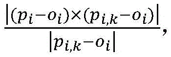
iTo obtain, assuming Ray
i,kHas a three-dimensional coordinate of o
iThe three-dimensional coordinate of the projection point is p
i,kThen minimum distance
If all the projection images exceed the threshold B, the sum p is
iIntersecting Ray
i,kIf not, deleting the position of the metal point from the set PI, and taking a threshold B as a parameter to be transmitted into the system during initialization;
(2.4) traversing PI, and calculating corresponding p according to the radius of the projection area
kBelongs to the three-dimensional radius of the PI position metal point, and the radius
Wherein, po
iIs the perpendicular projection of the source point on the projection plane, sdd
iSource range representing the ith projection view, and PS { (p) is formed
1,r
1),…,(p
m,r
m)},p
i∈PI。
Has the advantages that: compared with the prior art, the method searches the metal mark on the projection drawing; screening metal mark points according to the three-dimensional projection relation of the metal coordinate; processing the projection drawing, and filling by utilizing projection peripheral information to obtain a two-dimensional projection drawing without metal mark projection; reconstructing by using the processed projection image to obtain a CT image without metal marks and metal artifacts; and processing the CT image and adding a metal mark part to obtain a complete cone beam CT image. The invention has high efficiency aiming at the spherical metal marking and is not easy to be interfered by noise.
Detailed Description
The invention is further described below with reference to the accompanying drawings. The following examples are only for illustrating the technical solutions of the present invention more clearly, and the protection scope of the present invention is not limited thereby.
As shown in fig. 1, the system for removing metal artifacts of cone beam CT with spherical metal markers according to the present invention includes a two-dimensional projection metal projection region processing module, a metal projection screening module, a three-dimensional reconstruction module, and a three-dimensional image processing module.
Furthermore, the two-dimensional projection graph metal projection area processing module is used for obtaining a separated metal mark projection area, an area center and an area radius on the two-dimensional projection graph, and filling the metal mark projection area according to the edge pixel value to remove the metal mark projection; the module provides two interfaces to the outside;
interface 1: providing a metal mark projection area separation function, inputting the metal mark projection area separation function into a projection graph, wherein the projection graph comprises image pixel information and geometric information of the pixels under a two-dimensional coordinate system of the projection graph, and the geometric information comprises two-dimensional coordinates of a first row and a first column in the graph and row-column spacing of the pixels in the graph; outputting a list of metal marking area information, wherein each metal marking area comprises an area center two-dimensional coordinate and an area radius;
and (3) interface 2: providing a function of filling a metal mark projection area according to an edge pixel value to remove a metal mark projection, inputting a projection graph and a list of metal mark area information, referring to an interface 1 for detailed information of the projection graph and the metal mark area information, and outputting the projection graph after processing;
the metal projection screening module; screening out feasible metal mark projection areas according to projection geometric parameters corresponding to centers, radiuses and projection angles of the metal mark projection areas in a plurality of projection drawings; the module provides an interface to the outside; the interface input is a metal mark area geometric double-layer list organized according to a projection drawing, each item in the list is a list of metal mark area information of the projection drawing, and each metal mark area comprises an area center two-dimensional coordinate and an area radius; outputting a three-dimensional metal mark list and a screened metal mark area geometric double-layer list organized according to a projection drawing, wherein each item in the three-dimensional metal mark list comprises a metal mark center three-dimensional coordinate and a metal mark radius;
the three-dimensional reconstruction module reconstructs a three-dimensional CT image based on the projection image; the module provides an interface to the outside; the interface input is a processed projection graph list containing geometric information, wherein each item is a projection graph and corresponding projection geometric information, and the projection geometric information comprises three-dimensional coordinates of a source in a world coordinate system, three-dimensional coordinates of a starting point of a projection graph flat plate and three-dimensional direction vectors of rows and columns of the projection graph flat plate; outputting the three-dimensional image after reconstruction;
the three-dimensional image processing module is a three-dimensional image part for adding metal marks in the CT image based on the coordinates and the radius of the metal marks; the module provides 1 interface, the input of the interface is a three-dimensional metal mark list, a three-dimensional image and a metal mark CT value, and the output is the three-dimensional image of which the pixel value is updated at the position of the metal mark as an input value.
Further, a method for removing spherical metal marked cone beam CT metal artifact removal system is characterized by comprising the following specific operation steps:
(1) primarily screening the projection graph to obtain a projection area of the metal marker;
(2) screening the projection area according to the central point and the radius of the metal projection area in each projection drawing and combining projection geometric information corresponding to the projection drawing, and obtaining the three-dimensional coordinates and the three-dimensional radius of the metal marker;
(3) for each projection image, screening out a true metal projection area according to a current PI three-dimensional coordinate, filling the true metal projection area with pixel information of the edge of the area, eliminating metal projection, and performing back projection reconstruction to obtain a cone beam CT without metal marks, wherein the back projection reconstruction algorithm is a general back projection reconstruction algorithm, such as an FDK back projection algorithm and the like;
(4) modifying p according to the reference CT value of the metal mark in cone beam CT without metal mark according to PSiPeripheral radius riAnd finally finishing the cone beam CT reconstruction process for removing the metal artifact by the internal CT pixel value.
Further, in step (1), the specific operation steps of preliminarily screening the projection map to obtain the projection area of the metal marker are as follows:
(1.1) obtained at different anglesObtaining the pixel position of the pixel value within a certain (whole image pixel value) proportion A through threshold segmentation on a series of perspective views, wherein the pixel value proportion A is different according to different applications and can be determined according to the number of the metal marks and the size of the metal marks, and the proportion can be determined through a formula
The calculation is carried out according to the calculation,
wherein R represents the radius of the metal mark, and R represents the field size; in specific implementation, A can be set to be less than 1%;
(1.2) carrying out corrosion expansion calculation based on the pixel position to obtain a high perspective density region which is not communicated with each other, namely a candidate region of the metal mark projection region, wherein the stop condition of a corrosion expansion operator is that the gradient of the pixel value at the pixel is greater than a certain threshold value, and the threshold value can be adjusted according to the actual situation to ensure that the size of the communicated region does not exceed the integral 2A proportion;
(1.3) obtaining a center point two-dimensional coordinate set PCS ═ PC of each candidate area in each perspective view
1,PC
2,…,PC
n},
Wherein pi isjTwo-dimensional coordinates, ri, representing the center point of the jth region on the projection at the ith anglejRepresenting the radius of the jth area on the ith angle lower projection diagram;
at this step, the center of the region, i.e., the center of the region, can be obtained by a weighted sum of pixel values
Wherein, (x, y) represents pixel coordinates within the region, and P (x, y) represents a pixel value at which the projection line passes through the substance stopping power; obtaining the area s of the region according to the number of pixels by
Obtaining a region radius;
further, in the step (2), the specific operation steps of screening the projection area according to the center point and the radius of the metal projection area in each projection drawing and combining the projection geometric information corresponding to the projection drawing and obtaining the three-dimensional coordinates and the three-dimensional radius of the metal marker are as follows:
(2.1) taking a projection view i of the divided metal marker, wherein the metal marker area obtained by preprocessing in the projection view is known to be the maximum in all the projection views;
(2.2) taking another projection graph j with the projection angle of i being 30-60 degrees, and aiming at each projection position pi in ikThree-dimensional Ray formed by X-Ray source pointsi,kTraversing the X-ray source point and the candidate metal projection point pi in the jlFormed Rayi,lAnd calculating to obtain each intersection point Pi,k,mThe m-th intersection point with the k-th projection point ray in the projection view i is represented, and all these intersection points are merged into one set PI ═ { p }1,p2,…,pn}={Pi,k,mIn (1) };
(2.3) for each p
iE, PI, and testing whether a metal point projection Ray exists in each projection graph or not
i,kIntersect it, where the intersection is judged by p
iAnd Ray
i,kIs smaller than the error r
iTo obtain, assuming Ray
i,kHas a three-dimensional coordinate of o
iThe three-dimensional coordinate of the projection point is p
i,kThen minimum distance
If all the projection images exceed the threshold B, the sum p is
iIntersecting Ray
i,kIf not, deleting the position of the metal point from the set PI, and taking a threshold B as a parameter to be transmitted into the system during initialization;
(2.4) traversing PI, and calculating corresponding p according to the radius of the projection area
kBelongs to the three-dimensional radius of the PI position metal point, and the radius
Wherein, po
iIs the perpendicular projection of the source point on the projection plane, sdd
iSource range representing the ith projection view, and PS { (p) is formed
1,r
1),…,(p
m,r
m)},p
i∈PI。
The above description is only for the specific embodiments of the present invention, but the scope of the present invention is not limited thereto, and any person skilled in the art can easily conceive of the changes or substitutions within the technical scope of the present invention, and all the changes or substitutions should be covered within the scope of the present invention. Therefore, the protection scope of the present invention shall be subject to the protection scope of the appended claims.