CN113710767A - Partially shaped abrasive particles, methods of manufacture, and articles comprising the partially shaped abrasive particles - Google Patents
Partially shaped abrasive particles, methods of manufacture, and articles comprising the partially shaped abrasive particles Download PDFInfo
- Publication number
- CN113710767A CN113710767A CN202080028699.6A CN202080028699A CN113710767A CN 113710767 A CN113710767 A CN 113710767A CN 202080028699 A CN202080028699 A CN 202080028699A CN 113710767 A CN113710767 A CN 113710767A
- Authority
- CN
- China
- Prior art keywords
- shaped
- partially
- shaped abrasive
- particles
- abrasive particles
- Prior art date
- Legal status (The legal status is an assumption and is not a legal conclusion. Google has not performed a legal analysis and makes no representation as to the accuracy of the status listed.)
- Granted
Links
Images


Classifications
-
- C—CHEMISTRY; METALLURGY
- C09—DYES; PAINTS; POLISHES; NATURAL RESINS; ADHESIVES; COMPOSITIONS NOT OTHERWISE PROVIDED FOR; APPLICATIONS OF MATERIALS NOT OTHERWISE PROVIDED FOR
- C09K—MATERIALS FOR MISCELLANEOUS APPLICATIONS, NOT PROVIDED FOR ELSEWHERE
- C09K3/00—Materials not provided for elsewhere
- C09K3/14—Anti-slip materials; Abrasives
- C09K3/1436—Composite particles, e.g. coated particles
-
- B—PERFORMING OPERATIONS; TRANSPORTING
- B24—GRINDING; POLISHING
- B24D—TOOLS FOR GRINDING, BUFFING OR SHARPENING
- B24D11/00—Constructional features of flexible abrasive materials; Special features in the manufacture of such materials
-
- B—PERFORMING OPERATIONS; TRANSPORTING
- B24—GRINDING; POLISHING
- B24D—TOOLS FOR GRINDING, BUFFING OR SHARPENING
- B24D18/00—Manufacture of grinding tools or other grinding devices, e.g. wheels, not otherwise provided for
- B24D18/0009—Manufacture of grinding tools or other grinding devices, e.g. wheels, not otherwise provided for using moulds or presses
-
- B—PERFORMING OPERATIONS; TRANSPORTING
- B24—GRINDING; POLISHING
- B24D—TOOLS FOR GRINDING, BUFFING OR SHARPENING
- B24D3/00—Physical features of abrasive bodies, or sheets, e.g. abrasive surfaces of special nature; Abrasive bodies or sheets characterised by their constituents
-
- C—CHEMISTRY; METALLURGY
- C01—INORGANIC CHEMISTRY
- C01G—COMPOUNDS CONTAINING METALS NOT COVERED BY SUBCLASSES C01D OR C01F
- C01G25/00—Compounds of zirconium
- C01G25/02—Oxides
-
- C—CHEMISTRY; METALLURGY
- C04—CEMENTS; CONCRETE; ARTIFICIAL STONE; CERAMICS; REFRACTORIES
- C04B—LIME, MAGNESIA; SLAG; CEMENTS; COMPOSITIONS THEREOF, e.g. MORTARS, CONCRETE OR LIKE BUILDING MATERIALS; ARTIFICIAL STONE; CERAMICS; REFRACTORIES; TREATMENT OF NATURAL STONE
- C04B35/00—Shaped ceramic products characterised by their composition; Ceramics compositions; Processing powders of inorganic compounds preparatory to the manufacturing of ceramic products
- C04B35/01—Shaped ceramic products characterised by their composition; Ceramics compositions; Processing powders of inorganic compounds preparatory to the manufacturing of ceramic products based on oxide ceramics
- C04B35/10—Shaped ceramic products characterised by their composition; Ceramics compositions; Processing powders of inorganic compounds preparatory to the manufacturing of ceramic products based on oxide ceramics based on aluminium oxide
- C04B35/111—Fine ceramics
- C04B35/1115—Minute sintered entities, e.g. sintered abrasive grains or shaped particles such as platelets
-
- C—CHEMISTRY; METALLURGY
- C09—DYES; PAINTS; POLISHES; NATURAL RESINS; ADHESIVES; COMPOSITIONS NOT OTHERWISE PROVIDED FOR; APPLICATIONS OF MATERIALS NOT OTHERWISE PROVIDED FOR
- C09K—MATERIALS FOR MISCELLANEOUS APPLICATIONS, NOT PROVIDED FOR ELSEWHERE
- C09K3/00—Materials not provided for elsewhere
- C09K3/14—Anti-slip materials; Abrasives
- C09K3/1409—Abrasive particles per se
-
- C—CHEMISTRY; METALLURGY
- C01—INORGANIC CHEMISTRY
- C01P—INDEXING SCHEME RELATING TO STRUCTURAL AND PHYSICAL ASPECTS OF SOLID INORGANIC COMPOUNDS
- C01P2004/00—Particle morphology
- C01P2004/30—Particle morphology extending in three dimensions
-
- C—CHEMISTRY; METALLURGY
- C01—INORGANIC CHEMISTRY
- C01P—INDEXING SCHEME RELATING TO STRUCTURAL AND PHYSICAL ASPECTS OF SOLID INORGANIC COMPOUNDS
- C01P2004/00—Particle morphology
- C01P2004/60—Particles characterised by their size
- C01P2004/64—Nanometer sized, i.e. from 1-100 nanometer
Landscapes
- Chemical & Material Sciences (AREA)
- Engineering & Computer Science (AREA)
- Organic Chemistry (AREA)
- Materials Engineering (AREA)
- Mechanical Engineering (AREA)
- Composite Materials (AREA)
- Manufacturing & Machinery (AREA)
- Ceramic Engineering (AREA)
- Inorganic Chemistry (AREA)
- Structural Engineering (AREA)
- Polishing Bodies And Polishing Tools (AREA)
Abstract
本发明所公开的各种实施方案涉及一种部分成形磨料颗粒。该部分成形磨料颗粒包括成形部分和不规则部分,其中成形部分被工程化成具有多边形形状。不规则部分连接到成形部分的基部,从而形成单个部分成形磨料颗粒。
Various embodiments disclosed herein relate to a partially shaped abrasive particle. The partially shaped abrasive particle includes a shaped portion and an irregular portion, wherein the shaped portion is engineered to have a polygonal shape. The irregularities are connected to the base of the shaped portion, thereby forming a single portion of shaped abrasive particles.
Description
Background
Abrasive particles and abrasive articles including abrasive particles can be used to abrade, polish, or grind a variety of materials and surfaces during the manufacture of the products. Accordingly, there is a continuing need for improved cost, performance, or life of abrasive particles or abrasive articles.
Disclosure of Invention
Various embodiments disclosed relate to partially shaped abrasive particles having shaped portions and irregular portions, wherein the shaped portions are engineered to have a polygonal shape. The shaped portion is joined to the irregular portion to form a single partially shaped abrasive particle.
Various other embodiments disclosed relate to a method of making partially shaped abrasive particles. The method includes disposing an abrasive particle precursor composition in a mold cavity conforming to a negative of a shaped portion of the partially shaped abrasive particles. The method also includes drying the abrasive particle precursor to form partially shaped abrasive particles. In some embodiments, the abrasive particles may optionally be treated by a firing process.
Various other embodiments disclosed relate to an abrasive article comprising partially shaped abrasive particles. The abrasive article includes a backing. The abrasive article further includes shaped abrasive particles attached to the backing.
Various other embodiments disclosed relate to a method of making an abrasive article. The method includes adhering a portion of the shaped abrasive particles to the backing such that the shaped portion of the shaped abrasive particles faces away from the backing.
There are many reasons for using the partially shaped abrasive particles and articles comprising the partially shaped abrasive particles described herein, including the following non-limiting reasons. At least some embodiments described herein exhibit improved resistance to spalling as compared to conventional precisely shaped abrasive particles. At least some embodiments described herein illustrate abrasive articles for cutting having more exposed precisely shaped particles. In addition, some embodiments described herein have improved mineral production. The manufacture of abrasive articles may also be improved by at least some embodiments described herein, thereby reducing costs through easier drop-on manufacturing. The presence of irregularities helps to ensure the correct orientation of the precisely shaped abrasive portions of the abrasive particles. Furthermore, articles incorporating such abrasive particles have a longer useful life due to the presence of more precisely shaped abrasive segments on the surface. In addition, portions of the shaped abrasive particles may be more easily coated because the shaped portions of the abrasive particles are more exposed.
Drawings
The drawings are generally shown by way of example, and not by way of limitation, to the various embodiments discussed in this document.
Fig. 1A-1C illustrate examples of partially shaped abrasive particles according to embodiments of the present invention.
Fig. 2 illustrates an exemplary method of making partially shaped abrasive particles according to an embodiment of the present invention.
Fig. 3 illustrates an exemplary article incorporating partially shaped abrasive particles according to embodiments of the present invention.
Fig. 4A-4B illustrate a prior art abrasive article as compared to an exemplary abrasive article according to an embodiment of the present invention.
Fig. 5A-5D illustrate another exemplary partially shaped abrasive particle according to another embodiment of the present invention.
Fig. 6 illustrates another exemplary method of making partially shaped abrasive particles according to another embodiment of the present invention.
Fig. 7-12 illustrate examples of partially shaped abrasive particles made according to embodiments described herein.
Detailed Description
Reference will now be made in detail to specific embodiments of the presently disclosed subject matter, examples of which are illustrated in the accompanying drawings. While the presently disclosed subject matter will be described in conjunction with the recited claims, it will be understood that the exemplary subject matter is not intended to limit the claims to the presently disclosed subject matter.
Throughout this document, values expressed in a range format should be interpreted in a flexible manner to include not only the numerical values explicitly recited as the limits of the range, but also to include all the individual numerical values or sub-ranges encompassed within that range as if each numerical value and sub-range is explicitly recited. For example, a range of "about 0.1% to about 5%" or "about 0.1% to 5%" should be interpreted to include not only about 0.1% to about 5%, but also include individual values (e.g., 1%, 2%, 3%, and 4%) and sub-ranges (e.g., 0.1% to 0.5%, 1.1% to 2.2%, 3.3% to 4.4%) within the indicated range. Unless otherwise indicated, the expression "about X to Y" has the same meaning as "about X to about Y". Likewise, unless otherwise indicated, the expression "about X, Y or about Z" has the same meaning as "about X, about Y, or about Z".
In this document, the terms "a", "an" or "the" are used to include one or more than one unless the context clearly indicates otherwise. The term "or" is used to refer to a non-exclusive "or" unless otherwise indicated. The expression "at least one of a and B" has the same meaning as "A, B or a and B". Also, it is to be understood that the phraseology or terminology employed herein, and not otherwise defined, is for the purpose of description only and not of limitation. Any use of section headings is intended to aid in the understanding of the document and should not be construed as limiting; information related to a section header may appear within or outside of that particular section.
In the methods described herein, various actions may be performed in any order, except when a time or sequence of operations is explicitly recited, without departing from the principles of the invention. Further, the acts specified may occur concurrently unless the express claim language implies that they occur separately. For example, the claimed act of performing X and the claimed act of performing Y may be performed simultaneously in a single operation, and the resulting process would fall within the literal scope of the claimed process.
As used herein, the term "about" can allow, for example, a degree of variability in the value or range, e.g., within 10%, within 5%, or within 1% of the stated value or limit of the range, and includes the exact stated value or range.
The term "substantially" as used herein refers to a majority or majority, such as at least about 50%, 60%, 70%, 80%, 90%, 95%, 96%, 97%, 98%, 99%, 99.5%, 99.9%, 99.99%, or at least about 99.999% or more, or 100%.
As used herein, the term "shaped abrasive particle" means an abrasive particle in which at least a portion of the abrasive particle has a predetermined shape that is replicated from a mold cavity used to form the shaped precursor abrasive particle. Except in the case of abrasive shards (e.g., as described in U.S. patent application publications 2009/0169816 and 2009/0165394), the shaped abrasive particles will typically have a predetermined geometry that substantially replicates the mold cavity used to form the shaped abrasive particles. As used herein, shaped abrasive particles do not include abrasive particles obtained by a mechanical crushing operation.
By "partially shaped abrasive particles" is meant abrasive particles having a portion of shaped abrasive particles attached to a non-shaped portion. For example, the non-shaped portions may be formed during the shredding operation. In some embodiments, "attached" refers to mechanical attachment using an adhesive. However, in other embodiments, "connected" means that the shaped portion and the non-shaped (irregular) portion are formed simultaneously as one integral piece.
Partially shaped abrasive particles
According to various embodiments of the present disclosure, the shaped abrasive particles provide improved performance over conventional crushed abrasives. Controlling the shape of the abrasive particles can control the resulting properties of abrasive articles incorporating the particles. However, the surface of the shaped abrasive particles is typically smoother than the surface on the crushed particles, which results in less mechanical locking between the mineral and binder layers. This can lead to flaking, which refers to the phenomenon of abrasive particles prematurely releasing from the bonding system. The bonding system is intended to retain the abrasive particles throughout their useful life. The term "flaking" may be based on a similar behavior of releasing corn kernels when the ear of corn is subjected to a flaking operation. Although there are some exceptions, it is generally undesirable for abrasive particles to flake off of the abrasive article, as this reduces the efficiency of the article as the abrasive surface is reduced. The efficiency loss represented by spalling occurs in all abrasive products, including bonded abrasive products (such as grinding wheels), nonwoven abrasive products, and coated abrasive products. The loss in coated abrasive space is particularly significant because substantially all of the abrasive particles are retained on the backing by the bonding system. Substantially each abrasive particle on the coated abrasive is exposed or nearly exposed. The loss of abrasive particles due to spalling results in non-abrasive regions on the abrasive article, reducing the grinding efficiency and can result in an uneven surface finish.
Abrasive products for high stock removal applications must be able to withstand high pressures and high rotational speeds while still providing adequate abrasive cutting. In such cases, flaking may be significant.
Conventional crushed mineral flakes are less exfoliated than precisely shaped abrasive particles because the rough surface of the crushed mineral particles provides a plurality of locking points for the binder, thereby securely retaining the abrasive particles during grinding applications.
Disclosed herein are novel abrasive particles that combine the higher machinability of shaped abrasive particles with the better adhesion and lower exfoliation rate of crushed minerals. In some embodiments, at least 15% of each particle is precisely shaped. In some embodiments, at least 30% of each particle is precisely shaped. Preferably, 50 to 95 volume% of each particle is precisely shaped.
At least some embodiments described herein exhibit improved resistance to spalling as compared to conventional precisely shaped abrasive particles. At least some embodiments described herein illustrate abrasive articles for cutting having more exposed precisely shaped particles. The presence of irregularities helps to ensure the correct orientation of the precisely shaped abrasive portions of the abrasive particles. Furthermore, articles incorporating such abrasive particles have a longer useful life due to the presence of more precisely shaped abrasive segments on the surface. In addition, portions of the shaped abrasive particles may be more easily coated because the shaped portions of the abrasive particles are more exposed.
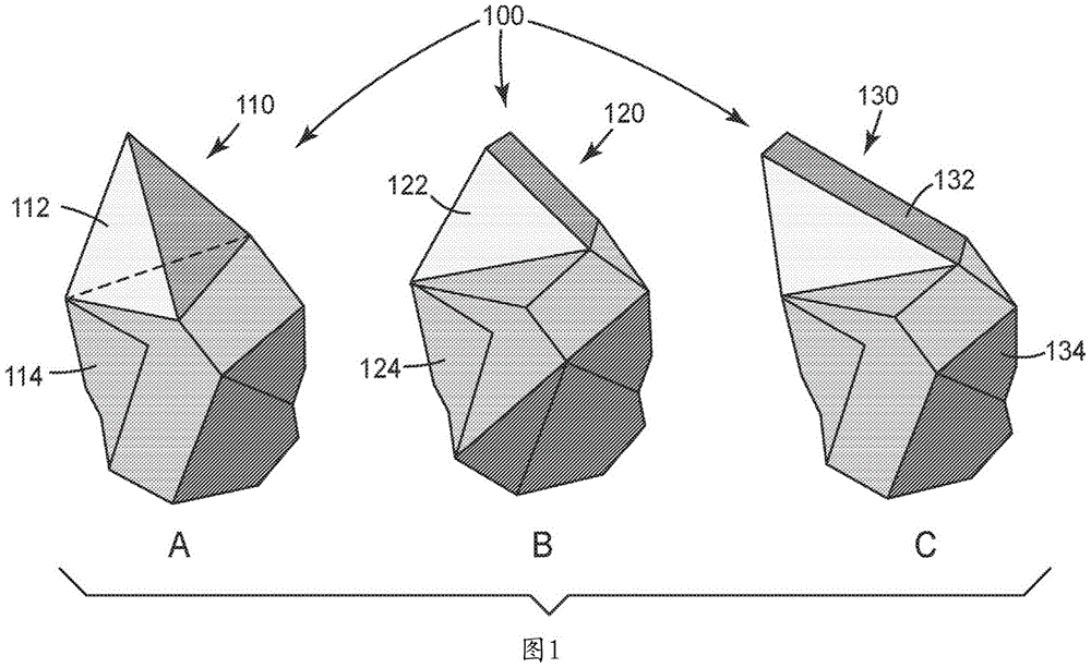
Fig. 1A-1C illustrate examples of partially shaped abrasive particles according to embodiments of the present invention. According to various embodiments described herein, partially shaped abrasive particles 100 can be engineered to have a desired shaped portion in combination with an irregularly shaped portion.
Fig. 1A illustrates an example of partially shaped abrasive particles according to embodiments described herein. Partially shaped abrasive particles 110 have shaped portions 112 (shown as tetrahedrons) and irregular portions 114.
The partially shaped abrasive particles 120 shown in fig. 1B are another example of partially shaped abrasive particles according to embodiments described herein. The partially shaped abrasive particles 120 have shaped portions 122 and irregular portions 124. The shaped portion 122 is a shaped abrasive particle having two faces, both triangular, separated by a thickness t. Each of the two faces shown in fig. 1B is an isosceles triangle.
The partially shaped abrasive particles 130 shown in fig. 1C are another embodiment. Partially shaped abrasive particles 130 have shaped portions 132 and irregular portions 134. The shaped portion 132 is a shaped abrasive particle having two faces, both triangular, separated by a thickness t. Each of the two faces shown in fig. 1C is a scalene triangle.
Fig. 1A-1C illustrate only some examples of possible shapes for the shaped abrasive particle portions 112, 122, and 132. For example, while the shaped portion 112 illustrates a tetrahedron, other pyramidal structures are also contemplated, including those having bases with 4, 5, or more sides. Additionally, while the shaped portion 112 illustrates a tetrahedron having four substantially identical faces, it is contemplated that other tetrahedral shapes are possible, including those having only two identical faces, three identical faces, or no substantially identical faces.
Additionally, while fig. 1B and 1C illustrate some exemplary triangular shaped abrasive sections 122 and 132, it is contemplated that other polygonal shapes may be used for one or more faces of the shaped section of abrasive particles, including polygons having four, five, or more sides.
The partially shaped abrasive particles of the present invention each have a shaped portion of a substantially precisely shaped three-dimensional shape. Typically, the shaped portion of each particle generally has a predetermined geometry, such as a geometry that substantially replicates the shaped portion of the mold cavity used to form the partially shaped abrasive particle.
Suitable examples of geometric shapes having a basis for the three-dimensional shape that can form the shaped portion of the partially shaped abrasive particle include polygons (including equilateral, equiangular, star-shaped, regular, and irregular polygons), lens shapes, half-moon shapes, circular shapes, semi-circular shapes, elliptical shapes, scallops, circular segments, drop shapes, and hypocycloids (e.g., superellipses).
For the purposes of the present invention, geometric shapes are also intended to include regular or irregular polygons or stars, wherein one or more sides (edge portions of a face) may be arcuate (inwardly or outwardly, with the first alternative being preferred). Triangular shapes also include three-sided polygons in which one or more sides (edge portions of a face) may be arcuate, i.e., the definition of a triangle expands to a spherical triangle and the definition of a quadrilateral expands to a hyperellipse. The second side may have (and preferably is) a second face. The second face may have edges of a second geometric shape.
Additionally, while the shaped portions 112, 122, and 132 are all shown as having smooth faces, it is also contemplated that in at least some embodiments, portions of the shaped abrasive particles have shaped portions with additional features. For example, one or more faces of the shaped abrasive portion can have grooves or ridges. In another example, one or more faces may be concave or convex.
Methods for making shaped abrasive particles having at least one sloping sidewall are described, for example, in U.S. patent application publication 2009/0165394. Methods for making shaped abrasive particles having openings are described, for example, in U.S. patent application publications 2010/0151201 and 2009/0165394. Methods for making shaped abrasive particles having a groove on at least one side are described, for example, in U.S. patent application publication 2010/0146867. Methods for making dish-shaped abrasive particles are described, for example, in U.S. patent application publications 2010/0151195 and 2009/0165394. Methods for making shaped abrasive particles having a low roundness factor are described, for example, in U.S. patent application publication 2010/0319269. Methods for making shaped abrasive particles having at least one fracture surface are described, for example, in U.S. patent application publications 2009/0169816 and 2009/0165394. Methods for making abrasive particles in which the second side has an apex (e.g., double wedge shaped abrasive particles) or ridge (e.g., roof shaped particles) are described, for example, in WO 2011/068714.
Composition of partially shaped abrasive particles
Portions of shaped abrasive particles 100 may be formed from a variety of suitable materials or combinations of materials. For example, portions of shaped abrasive particles 100 may be a ceramic material or a polymeric material. If portions of shaped abrasive particles 100 are made of a ceramic material, the ceramic material may include alpha alumina, alpha alumina derived from a sol-gel process, or a mixture thereof. Other suitable materials include fused aluminum oxide, heat treated aluminum oxide, ceramic aluminum oxide, sintered aluminum oxide, silicon carbide material, titanium diboride, boron carbide, tungsten carbide, titanium carbide, diamond, cubic boron nitride, garnet, fused alumina-zirconia, ceria, zirconia, titania, or combinations thereof. Additionally, as discussed in more detail below in connection with fig. 5-6, it is also expressly contemplated that in some embodiments, the shaped portions of partially shaped abrasive particles 100 are a different material than the irregular portions.
Partially shaped abrasive particles 100 comprising a polymeric material can be characterized as soft abrasive particles. The soft shaped abrasive particles described herein can comprise any suitable material or combination of materials. For example, the soft shaped abrasive particles can comprise the reaction product of a polymerizable mixture comprising one or more polymerizable resins. The one or more polymerizable resins are selected from the group consisting of phenolic resins, urea-formaldehyde resins, urethane resins, melamine resins, epoxy resins, bismaleimide resins, vinyl ether resins, aminoplast resins (which may include pendant alpha, beta unsaturated carbonyl groups), acrylate resins, acrylated isocyanurate resins, acrylated urethane resins, acrylated epoxy resins, alkyl resins, polyester resins, drying oils, or mixtures thereof. The polymerizable mixture may include additional components such as plasticizers, acid catalysts, crosslinkers, surfactants, mild abrasives, pigments, catalysts, and antimicrobial agents.
Where multiple components are present in the polymerizable mixture, these components can comprise any suitable weight percent of the mixture. For example, the polymerizable resin may be in a range of about 35 wt% to about 99.9 wt%, about 40 wt% to about 95 wt%, or may be less than, equal to, or greater than about 35 wt%, 40 wt%, 41 wt%, 42 wt%, 43 wt%, 44 wt%, 45 wt%, 46 wt%, 47 wt%, 48 wt%, 49 wt%, 50 wt%, 51 wt%, 52 wt%, 53 wt%, 54 wt%, 55 wt%, 56 wt%, 57 wt%, 58 wt%, 59 wt%, 60 wt%, 61 wt%, 62 wt%, 63 wt%, 64 wt%, 65 wt%, 66 wt%, 67 wt%, 68 wt%, 69 wt%, 70 wt%, 71 wt%, 72 wt%, 73 wt%, 74 wt%, 75 wt%, 76 wt%, 77 wt%, 78 wt% of the polymerizable mixture, 79, 80, 81, 82, 83, 84, 85, 86, 87, 88, 89, 90, 91, 92, 93, 94, 95, 96, 97, 98, or about 99.9 wt%.
If present, the crosslinking agent can be in a range of about 2 wt% to about 60 wt%, about 5 wt% to about 10 wt% of the polymerizable mixture, or can be less than, equal to, or greater than about 2 wt%, 3 wt%, 4 wt%, 5 wt%, 6 wt%, 7 wt%, 8 wt%, 9 wt%, 10 wt%, 11 wt%, 12 wt%, 13 wt%, 14 wt%, or about 15 wt%. Examples of suitable crosslinking agents include those available under the tradename CYMEL 303LF from the knifing united states corporation of alpha lita, Georgia, USA (Allnex USA inc., Alpharetta, Georgia, USA); or a crosslinker available under the tradename CYMEL 385 from the knifing U.S. gmbh of alpha lita, georgia.
If present, the mild abrasive may be in the range of about 5 wt% to about 65 wt%, about 10 wt% to about 20 wt% of the polymerizable mixture, or may be less than, equal to, or greater than about 5 wt%, 6 wt%, 7 wt%, 8 wt%, 9 wt%, 10 wt%, 11 wt%, 12 wt%, 13 wt%, 14 wt%, 15 wt%, 16 wt%, 17 wt%, 18 wt%, 19 wt%, 20 wt%, 21 wt%, 22 wt%, 23 wt%, 24 wt%, 25 wt%, 26 wt%, 27 wt%, 28 wt%, 29 wt%, 30 wt%, 31 wt%, 32 wt%, 33 wt%, 34 wt%, 35 wt%, 36 wt%, 37 wt%, 38 wt%, 39 wt%, 40 wt%, 41 wt%, 42 wt%, 43 wt% of the polymerizable mixture, 44, 45, 46, 47, 48, 49, 50, 51, 52, 53, 54, 55, 56, 57, 58, 59, 60, 61, 62, 63, 64, or about 65 wt%. Examples of suitable mild abrasives include mild abrasives available under the trade designation MINSTRON 353TALC from American company for England porcelain TALC (Imerys Talc America, Inc., Three forms, Montana, USA) of Silivock, Monda; a mild abrasive available under the trade designation USG TERRA ALBA NO.1CALCIUM SULFATE from USG Corporation of Chicago, Ill. (USG Corporation, Chicago, Illinois, USA), USA; recycled glass (sand No. 40-70), silica, calcite, nepheline, syenite, calcium carbonate or mixtures thereof available from ESCA Industries ltd, Hatfield, Pennsylvania, USA of hattfield.
If present, the plasticizer can be in a range of about 5 wt% to about 40 wt%, about 10 wt% to about 15 wt%, or less than, equal to, or greater than about 5 wt%, 6 wt%, 7 wt%, 8 wt%, 9 wt%, 10 wt%, 11 wt%, 12 wt%, 13 wt%, 14 wt%, 15 wt%, 16 wt%, 17 wt%, 18 wt%, 19 wt%, 20 wt%, 21 wt%, 22 wt%, 23 wt%, 24 wt%, 25 wt%, 26 wt%, 27 wt%, 28 wt%, 29 wt%, 30 wt%, 31 wt%, 32 wt%, 33 wt%, 34 wt%, 35 wt%, 36 wt%, 37 wt%, 38 wt%, 39 wt%, or 40 wt% of the polymerizable mixture. Examples of suitable plasticizers include acrylic resins or styrene butadiene resins. Examples of acrylic resins include acrylic resins available under the trade name RHOPLEX GL-618 from Dow Chemical Company, Midland, Michigan, USA, Midland, Mich; acrylic resins available from Lubrizol Corporation, Wickliffe, Ohio, USA under the trade name HYCAR 2679; acrylic resins available from luobo wet of victori, ohio, under the trade name HYCAR 26796; polyether polyols available under the trade designation ARCOL LG-650 from Dow chemical company of Midland, Mich; or acrylic resins available from luobo inc of victori, ohio under the trade name HYCAR 26315. Examples of styrene butadiene resins include resins available from maillard Creek Polymers, inc., Charlotte, North Carolina, USA under the trade name roven 5900.
The acid catalyst, if present, can be in a range of from 1 wt% to about 20 wt%, about 5 wt% to about 10 wt%, or can be less than, equal to, or greater than about 1 wt%, 2 wt%, 3 wt%, 4 wt%, 5 wt%, 6 wt%, 7 wt%, 8 wt%, 9 wt%, 10 wt%, 11 wt%, 12 wt%, 13 wt%, 14 wt%, 15 wt%, 16 wt%, 17 wt%, 18 wt%, 19 wt%, or about 20 wt% of the polymerizable mixture. Examples of suitable acid catalysts include aluminum chloride solution or ammonium chloride solution.
If present, the surfactant can be in a range of about 0.001 wt% to about 15 wt%, about 5 wt% to about 10 wt% of the polymerizable mixture, or can be less than, equal to, or greater than about 0.001 wt%, 0.01 wt%, 0.5 wt%, 1 wt%, 2 wt%, 3 wt%, 4 wt%, 5 wt%, 6 wt%, 7 wt%, 8 wt%, 9 wt%, 10 wt%, 11 wt%, 12 wt%, 13 wt%, 14 wt%, or about 15 wt%. Examples of suitable surfactants include those available under the trade name GEMTEX SC-85-P from Innospec functional Chemicals of solvay, North Carolina (Innospec Performance Chemicals, Salisbury, North Carolina, USA); surfactants available under the trade name DYNOL 604 from Air Products and Chemicals, inc, Allentown, Pennsylvania, USA; a surfactant available from Dow chemical company of Midland, Mich.Mich.S.A. under the tradename ACRYSOL RM-8W; or surfactants available from the dow chemical company of midland, michigan under the tradename xiamater AFE 1520.
If present, the antimicrobial agent can be in a range of 0.5 wt% to about 20 wt%, about 10 wt% to about 15 wt%, or can be less than, equal to, or greater than about 0.5 wt%, 1 wt%, 2 wt%, 3 wt%, 4 wt%, 5 wt%, 6 wt%, 7 wt%, 8 wt%, 9 wt%, 10 wt%, 11 wt%, 12 wt%, 13 wt%, 14 wt%, 15 wt%, 16 wt%, 17 wt%, 18 wt%, 19 wt%, or about 20 wt% of the polymerizable mixture. Examples of suitable antimicrobial agents include zinc pyrithione.
The pigment, if present, can be in a range of about 0.1 wt% to about 10 wt%, about 3 wt% to about 5 wt% of the polymerizable mixture, or can be less than, equal to, or greater than about 0.1 wt%, 0.2 wt%, 0.4 wt%, 0.6 wt%, 0.8 wt%, 1 wt%, 1.5 wt%, 2 wt%, 2.5 wt%, 3 wt%, 3.5 wt%, 4 wt%, 4.5 wt%, 5 wt%, 5.5 wt%, 6 wt%, 6.5 wt%, 7 wt%, 7.5 wt%, 8 wt%, 8.5 wt%, 9 wt%, 9.5 wt%, or 10 wt%. Examples of suitable pigments include pigment dispersions available under the trade name SUNSPERSE BLUE 15 from Sun Chemical Corporation, Parsippany, New Jersey, USA, Parsippany, N.J.; pigment dispersions available under the tradename SUNSPERSE VIOLET 23 from solar chemical ltd, paspalnib, new jersey; pigment dispersions available under the name SUN BLACK from solar chemical ltd, pasipanib, new jersey; or PIGMENT dispersions available from Clariant ltd, Charlotte, North Carolina, USA under the trade name BLUE PIGMENT B2G, Charlotte, USA.
In addition to the materials already described, at least one magnetic material may be included within or coated onto shaped abrasive particles 100. Examples of magnetic materials include iron; cobalt; nickel; various nickel and iron alloys sold as various grades of Permalloy (Permalloy); various alloys of iron, nickel and cobalt sold as iron-nickel-cobalt alloy (Fernico), Kovar, iron-nickel-cobalt alloy i (Fernico i), or iron-nickel-cobalt alloy ii (Fernico ii); various alloys of iron, aluminum, nickel, cobalt and sometimes copper and/or titanium sold as various grades of Alnico (Alnico); alloys of iron, silicon and aluminum (about 85:9:6 by weight) sold as iron-aluminum-silicon alloys; heusler alloys (e.g. Cu)2MnSn); manganese bismuthate (also known as manganese bismuthate (Bismanol)); rare earth magnetizable materials, such as alloys of gadolinium, dysprosium, holmium, europium oxide, neodymium, iron, and boron (e.g., Nd)2Fe14B) And alloys of samarium and cobalt (e.g., SmCo)5);MnSb;MnOFe2O3;Y3Fe5O12;CrO2(ii) a MnAs; ferrites such as ferrite, magnetite; zinc ferrite; nickel ferrite; cobalt ferrite, magnesium ferrite, barium ferrite and the likeAnd strontium ferrite; yttrium iron garnet; and combinations of the foregoing. In some embodiments, the magnetizable material is an alloy containing 8 to 12 wt.% aluminum, 15 to 26 wt.% nickel, 5 to 24 wt.% cobalt, up to 6 wt.% copper, up to 1 wt.% titanium, with the balance up to 100 wt.% of the material in total being iron. In some other embodiments, the magnetizable coating may be deposited on abrasive particle 100 using a vapor deposition technique such as, for example, Physical Vapor Deposition (PVD), including magnetron sputtering. The inclusion of such magnetizable materials may allow portions of shaped abrasive particle 100 to be responsive to a magnetic field. Any of the partially shaped abrasive particles 100 may comprise the same material or comprise different materials.
However, in some embodiments, the partially shaped abrasive particles are free of added magnetizable material. It may not be necessary to add a magnetisable material to ensure proper placement of the particles on the backing. The incorporation of irregularities in a portion of the shaped abrasive particles can result in the particles self-orienting by changing their center of gravity such that the irregularly shaped portion faces the backing and the partially shaped portion faces away from the backing. For example, the incorporation of irregularities in partially shaped abrasive particles results in a center of gravity located at the irregularly shaped end, which can result in the particles self-orienting such that the irregularly shaped portions face toward the backing and the partially shaped portions face away from the backing.
Method of making partially shaped abrasive particles
The partially shaped abrasive particles 100 may be formed in any number of suitable ways, for example, the partially shaped abrasive particles 100 may be made according to a multi-operation method, such as the method discussed below, for example, with reference to fig. 2. The process can be carried out using any material or precursor dispersion material. Briefly, for embodiments in which the partially-shaped abrasive particle 100 is a monolithic ceramic particle, the method may include the operations of: preparing a seeded or unseeded precursor dispersion that can be converted to the corresponding (e.g., boehmite sol-gel that can be converted to alpha alumina); filling one or more mold cavities conforming to the negative of the partially shaped portions of abrasive particles 100 with the precursor dispersion; drying the precursor dispersion to form a shaped abrasive particle precursor; removing portions of the precursor shaped abrasive particles 100 from the mold cavity, thereby forming irregularities of each abrasive particle; calcining the precursor partially shaped abrasive particles 100 to form calcined precursor partially shaped abrasive particles 100; the calcined partially shaped abrasive particle 100 precursor is then sintered to form shaped abrasive particles 100. The method will now be described in more detail in the context of partially shaped abrasive particles 100 comprising alpha-alumina. In other embodiments, the mold cavity can be filled with melamine to form melamine partially shaped abrasive particles. In addition, other precursor materials may also be used in the context of the method shown in fig. 2 in order to form other suitable partially shaped abrasive particles.
The method can include an operation of providing a seeded or unseeded precursor dispersion that can be converted to a ceramic. In the example of seeding the precursor, the precursor may be seeded with iron oxide (e.g., FeO). The precursor dispersion may comprise a liquid as the volatile component. In one example, the volatile component is water. The dispersion may contain a sufficient amount of liquid to make the viscosity of the dispersion low enough to fill the mold cavity and replicate the mold surface, but not so much liquid as to result in excessive costs for subsequent removal of the liquid from the mold cavity. In one example, the precursor dispersion comprises 2 to 90 wt% of particles capable of being converted to ceramic, such as alumina monohydrate (boehmite) particles, and at least 10 wt%, or 50 to 70 wt%, or 50 to 60 wt% of a volatile component, such as water. Conversely, in some embodiments, the precursor dispersion comprises from 30 wt% to 50 wt% or from 40 wt% to 50 wt% solids.
Fig. 2 illustrates an exemplary method of making partially shaped abrasive particles according to an embodiment of the present invention. In one embodiment, the method 200 may be used to form partially shaped abrasive particles based on alpha alumina. However, other materials may be used.
In step 210, the mold 202 with the partially-shaped cavity 204 is filled with a precursor slurry 212. As shown, the precursor slurry 212 substantially completely fills the partially-formed cavity 204. Each of the cavities 204 extending into the mold 202 has a shape that will form the basis of a shaped portion of a partially shaped abrasive particle. For example, in the context of partially shaped abrasive particles 110, the partially shaped cavities 204 will be tetrahedral, while in the context of partially shaped abrasive particles 120, the partially shaped cavities 204 will be triangular prisms. However, other shapes are also contemplated for the partially-shaped cavity 204.
In step 220, the precursor slurry 212 undergoes a drying stage, thereby producing dry agglomerates 222 within the mold 202.
The dried agglomerates 220 then undergo a pulverization stage at step 230 to provide partially shaped abrasive particles 250, which are then removed from the mold 202 at step 240.
As shown, partially shaped abrasive particles 250 have shaped portions 252 and irregular portions 254.
Examples of suitable precursor dispersions include zirconia sols, vanadia sols, ceria sols, alumina sols, and combinations thereof. Suitable alumina dispersions include, for example, boehmite dispersions as well as other alumina hydrate dispersions. Boehmite can be prepared by known techniques or is commercially available. Examples of commercially available boehmite include products sold under the trade names "DISPERAL" and "DISPAL" both available from Sasol North America, Inc., or under the trade name "HIQ-40" available from BASF. These alumina monohydrate are relatively pure; that is, they contain relatively few, if any, other hydrate phases in addition to a monohydrate, and have a high surface area.
The physical properties of the resulting partially shaped abrasive particles 100 may generally depend on the type of material used in the precursor dispersion. As used herein, a "gel" is a three-dimensional network of solids dispersed in a liquid.
The precursor dispersion may comprise a modifying additive or a precursor of a modifying additive. Modifying additives may be used to enhance certain desired characteristics of the abrasive particles or to increase the efficiency of subsequent sintering steps. The modifying additive or precursor of the modifying additive may be in the form of a soluble salt, such as a water soluble salt. They may include metal-containing compounds and may be precursors of oxides of magnesium, zinc, iron, silicon, cobalt, nickel, zirconium, hafnium, chromium, yttrium, praseodymium, samarium, ytterbium, neodymium, lanthanum, gadolinium, cerium, dysprosium, erbium, titanium, and mixtures thereof. The specific concentrations of these additives that may be present in the precursor dispersion may vary.
The introduction of the modifying additive or modifying additive precursor can result in gelation of the precursor dispersion. The precursor dispersion can also be gelled by: the heating is carried out over a period of time so as to reduce the liquid content of the dispersion by evaporation. The precursor dispersion may further comprise a nucleating agent. Nucleating agents suitable for use in the present disclosure may include fine particles of alpha alumina, alpha iron oxide or precursors thereof, titanium dioxide and titanates, chromium oxide, or any other substance that nucleates the transformation. If a nucleating agent is used, it should be present in sufficient quantity to convert the alpha alumina.
A peptizing agent can be added to the precursor dispersion to produce a more stable hydrosol or colloidal precursor dispersion. Suitable peptizing agents are monoprotic acids or acidic compounds, such as acetic acid, hydrochloric acid, formic acid and nitric acid. Polyprotic acids may also be used, but they may rapidly gel the precursor dispersion, making it difficult to handle or introduce additional components. Certain commercial sources of boehmite contain an acid titer (e.g., absorbed formic or nitric acid) that aids in the formation of a stable precursor dispersion.
The precursor dispersion can be formed by any suitable means; for example, in the case of a sol-gel alumina precursor, it can be formed by simply mixing alumina monohydrate with water containing a peptizing agent, or by forming an alumina monohydrate slurry with added peptizing agent.
An anti-foaming agent or other suitable chemical may be added to reduce the tendency of air bubbles or entrained air to form during mixing. Other chemicals such as wetting agents, alcohols or coupling agents may be added if desired.
Further operations may include providing a mold having at least one mold cavity, or a plurality of cavities formed in at least one major surface of the mold. In some examples, the mold is formed as a production tool, which may be an applicator roll such as a belt, sheet, continuous web, rotary gravure roll, sleeve mounted on an applicator roll, or a die. In one example, the production tool may comprise a polymeric material. Examples of suitable polymeric materials include thermoplastics such as polyesters, polycarbonates, poly (ether sulfone), poly (methyl methacrylate), polyurethanes, polyvinyl chloride, polyolefins, polystyrene, polypropylene, polyethylene, or combinations thereof, or thermosets. In one example, the entire mold is made of a polymeric or thermoplastic material. In another example, the surfaces of the mold (such as the surfaces of the plurality of cavities) that are contacted with the precursor dispersion when the precursor dispersion is dried comprise a polymeric or thermoplastic material, and other portions of the mold can be made of other materials. By way of example, a suitable polymer coating may be applied to the metal mold to alter its surface tension characteristics.
Polymeric or thermoplastic production tools can be replicated from a metal master tool. The master tool can have the inverse pattern desired for the production tool. The master tool can be made in the same manner as the production tool. In one example, the master tool is made of metal (e.g., nickel) and diamond turned. In one example, the master tool is formed at least in part using stereolithography techniques. The polymeric sheet material can be heated along with the master tool such that the master tool pattern is imprinted on the polymeric material by pressing the two together. A polymer or thermoplastic material can also be extruded or cast onto the master tool and then pressed. The thermoplastic material is cooled to harden it, thereby producing the production tool. If a thermoplastic production tool is utilized, care should be taken not to generate excessive heat, which can deform the thermoplastic production tool, thereby limiting its life.
The cavity is accessible from an opening in either the top or bottom surface of the mold. In some examples, the cavity may extend through the entire thickness of the mold. Alternatively, the cavity may extend only a portion of the thickness of the mold. In one example, the top surface is substantially parallel to the bottom surface of the mold, wherein the cavities have a substantially uniform depth. At least one side of the mold, i.e., the side in which the cavity is formed, may remain exposed to the ambient atmosphere during the step of removing the volatile component.
The cavities 204 have a specified three-dimensional shape to produce shaped portions of partially shaped abrasive particles 100. The depth of a given cavity 204 may be uniform or may vary along its length and/or width. The cavities of a given mold may have the same shape or different shapes. Additionally, the cavities 204 may be spaced closer together or further apart depending on the desired size of the irregularities of the partially shaped abrasive particle 100. It should be understood that the die 202 may not be drawn to scale in fig. 2. The cavities 204 may also have smooth walls, or they may have textured walls that impart texture to the shaped portions of the partially shaped abrasive particles 100. Cavity 204 may also be shaped to impart one or more concavities or convexities to shaped portions of partially shaped abrasive particle 100.
Additional operations involve filling the cavity 204 with the precursor dispersion (e.g., by conventional techniques), for example, as shown at step 210. In some examples, a knife roll coater or a vacuum slot die coater may be used. If desired, a release agent may be used to aid in the removal of the particles from the mold. Examples of release agents include oils (such as peanut oil or mineral oil, fish oil), silicones, polytetrafluoroethylene, zinc stearate, and graphite. Generally, a release agent such as peanut oil in a liquid such as water or alcohol is applied to the surface of the production mold in contact with the precursor dispersion so that when release is desired, about 0.1mg/in is present per unit area of mold2(0.6mg/cm2) To about 3.0mg/in2(20mg/cm2) Or about 0.1mg/in2(0.6mg/cm2) To about 5.0mg/in2(30mg/cm2) The mold release agent of (1). In some embodiments, the top surface of the mold is coated with the precursor dispersion. The precursor dispersion can be pumped onto the top surface.
In a further operation, a doctor blade or smoothing bar may be used to completely press the precursor dispersion into the cavity 204 of the mold 202. The remaining portion of the precursor dispersion that does not enter the cavity 204 can be removed from the top surface of the mold 202 and recycled. In some examples, a small portion of the precursor dispersion may remain on the top surface, and in other examples, the top surface is substantially free of dispersion. The pressure applied by the doctor blade or smoothing bar may be less than 100psi (0.6MPa), or less than 50psi (0.3MPa), or even less than 10psi (60 kPa). In some examples, the exposed surface of the precursor dispersion does not substantially extend beyond the top surface.
In those instances where it is desirable to form a planar surface of the shaped ceramic abrasive particles using the exposed surfaces of the cavities, it may be desirable to overfill the cavities (e.g., using a micro-nozzle array) and slowly dry the precursor dispersion.
A further operation involves removing volatile components to dry the dispersion. Volatile components can be removed by a rapid evaporation rate. In some examples, the removal of the volatile component by evaporation is performed at a temperature above the boiling point of the volatile component. The upper limit of the drying temperature generally depends on the material from which the mold is made. For polypropylene molds, the temperature should be below the melting point of the plastic. In one example, the drying temperature may be about 90 ℃ to about 165 ℃, or about 105 ℃ to about 150 ℃, or about 105 ℃ to about 120 ℃ for an aqueous dispersion containing about 40% to 50% solids and a polypropylene mold. Higher temperatures can lead to improved production speeds, but can also lead to degradation of the polypropylene mold, thereby limiting its useful life as a mold.
During drying, the precursor dispersion shrinks, typically causing retraction from the chamber walls. For example, if the cavity has planar walls, the resulting partially shaped abrasive particle 100 may tend to have at least three concave major sides. It has now been found that by recessing the cavity walls (and thus increasing the cavity volume), a partially shaped abrasive particle 100 having at least three substantially planar major sides can be obtained. The extent of dishing generally depends on the solids content of the precursor dispersion.
Additional operations involve removing the resulting partially shaped abrasive particle 100 precursor from the cavity 204. Portions of the precursor shaped abrasive particles 100 may be removed from the cavities 204 by using the following methods for the mold 202, either alone or in combination: gravity, vibration, ultrasonic vibration, vacuum, or pressurized air to remove the particles 100 from the cavity 204.
Portions of the precursor shaped abrasive particles 100 may be further dried outside of the mold 202. This additional drying step is not necessary if the precursor dispersion is dried to the desired extent in the mold 202. However, in some cases, it may be economical to employ this additional drying step to minimize the residence time of the precursor dispersion in the mold 202. A portion of the precursor shaped abrasive particles 100 will be dried at a temperature of 50 ℃ to 160 ℃, or 120 ℃ to 150 ℃, for 10 minutes to 480 minutes, or 120 minutes to 400 minutes.
Additional operations involve calcining the partially shaped abrasive particle 100 precursor. During calcination, substantially all volatile materials are removed and the various components present in the precursor dispersion are converted to metal oxides. Typically, a portion of the precursor shaped abrasive particles 100 is heated to a temperature of 400 ℃ to 800 ℃ and maintained within this temperature range until the free water and 90 wt.% or more of any bound volatile materials are removed. In an optional step, it may be desirable to introduce the modifying additive by an impregnation process. The water-soluble salt may be introduced by injecting it into the pores of the calcined precursor partially shaped abrasive particle 100. The partially shaped abrasive particle 100 precursor is then pre-fired again.
Additional operations may involve sintering the calcined precursor partially-shaped abrasive particle 100 to form the partially-shaped particle 100. However, in some examples where the precursor comprises a rare earth metal, sintering may not be necessary. Prior to sintering, the calcined precursor partially-shaped abrasive particles 100 are not fully densified and therefore lack the desired hardness for use as partially-shaped abrasive particles 100. Sintering is performed by heating the calcined precursor partially shaped abrasive particle 100 to a temperature of 1000 ℃ to 1650 ℃. To achieve this degree of conversion, the length of time that the calcined precursor shaped abrasive particle 100 can be exposed to the sintering temperature depends on a variety of factors, but can be from five seconds to 48 hours.
In another embodiment, the duration of the sintering step is in the range of one minute to 90 minutes. After sintering, the shaped abrasive particles 14 may have a Vickers hardness of 10GPa (gigapascals), 16GPa, 18GPa, 20GPa, or greater.
The process can be modified using additional operations such as rapid heating of the material from the calcination temperature to the sintering temperature and centrifuging the precursor dispersion to remove sludge and/or waste. Furthermore, the method can be modified, if desired, by combining two or more of the method steps.
To form the soft segment shaped abrasive particles 100, a polymerizable mixture as described herein can be deposited in the cavities. The cavities may have a shape corresponding to a desired negative impression of the partially shaped abrasive particles 100. After filling the cavity to the desired degree, the polymerizable mixture is cured in the cavity. Curing may occur at room temperature (e.g., about 25 ℃) or at any temperature above room temperature. Curing can also be accomplished by exposing the polymerizable mixture to a source of electromagnetic radiation or ultraviolet radiation.
The partially shaped abrasive particles 100 can be independently sized according to an abrasives industry recognized specified nominal grade. The abrasive industry recognized grading standards include those promulgated by ANSI (american national standards institute), FEPA (european union of abrasives manufacturers), and JIS (japanese industrial standard). ANSI grade designations (i.e., specified nominal grades) include, for example: ANSI 4, ANSI 6, ANSI 8, ANSI 16, ANSI 24, ANSI 36, ANSI 46, ANSI 54, ANSI 60, ANSI 70, ANSI 80, ANSI 90, ANSI 100, ANSI 120, ANSI 150, ANSI 180, ANSI 220, ANSI 240, ANSI 280, ANSI 320, ANSI 360, ANSI 400, and ANSI 600. FEPA grade designations include F4, F5, F6, F7, F8, F10, F12, F14, F16, F18, F20, F22, F24, F30, F36, F40, F46, F54, F60, F70, F80, F90, F100, F120, F150, F180, F220, F230, F240, F280, F320, F360, F400, F500, F600, F800, F1000, F1200, F1500, and F2000. JIS grade designations include: JIS8, JIS12, JIS16, JIS24, JIS36, JIS46, JIS54, JIS60, JIS80, JIS100, JIS150, JIS180, JIS220, JIS240, JIS280, JIS320, JIS360, JIS400, JIS600, JIS800, JIS1000, JIS1500, JIS2500, JIS4000, JIS6000, JIS8000 and JIS10,000.
Abrasive article comprising partially shaped abrasive particles
In accordance with various embodiments of the present disclosure, an abrasive article is disclosed. The abrasive article may be selected from a number of different abrasive articles, such as a belt, a pad, or a disc. In one embodiment, the abrasive article may be a coated abrasive article in which partially shaped abrasive particles are applied to a backing and held in place with one or more coatings.
Shaped abrasive particles 100 may comprise 100% by weight of the abrasive particles in any abrasive article. Alternatively, the shaped abrasive particles 100 may be part of a blend of abrasive particles distributed on a backing. If present as part of a blend, the shaped abrasive particles 100 can be in a range from about 5 wt% to about 95 wt%, about 10 wt% to about 80 wt%, about 30 wt% to about 50 wt% of the blend, or less than, equal to, or greater than about 5 wt%, 10 wt%, 15 wt%, 20 wt%, 25 wt%, 30 wt%, 35 wt%, 40 wt%, 45 wt%, 50 wt%, 55 wt%, 60 wt%, 65 wt%, 70 wt%, 75 wt%, 80 wt%, 85 wt%, 90 wt%, or about 95 wt% of the blend. In the blend, the remainder of the abrasive particles may comprise conventional crushed abrasive particles. Crushed abrasive particles are typically formed by a mechanical crushing operation and do not have a replicated shape. The remainder of the abrasive particles may also include other shaped abrasive particles.
Fig. 3 illustrates an exemplary article incorporating partially shaped abrasive particles according to embodiments of the present invention. According to one embodiment of the present invention, coated abrasive article 300 is presented as an example of an abrasive article incorporating partially shaped abrasive particles 330. However, other forms of abrasive articles are also expressly contemplated. For example, in some embodiments, the shaped abrasive particles 100 may be included in a random orbital sander or a vibratory sander.
In one embodiment, the abrasive article 300 has a backing 310 with a layer of a first bonding material, such as a make layer 320, applied thereto. The partially shaped abrasive particles 330 are placed on the backing 310 such that they are attached to or partially embedded within the make coat 320. It is desirable that substantially all, or at least a majority, of the portions of shaped abrasive particles 330 be positioned within the make coat such that irregular portion 370 faces the backing 310 and shaped portion 360 faces away from the backing 310. This may increase the cut of the abrasive article 300 compared to a corresponding abrasive article with fewer or no partially shaped particles with shaped portions oriented away from the backing.
The backing 310 may be flexible or rigid. Examples of suitable materials for forming the flexible backing include polymeric films, metal foils, woven fabrics, knitted fabrics, paper, vulcanized fiber, staple fiber, continuous fiber, nonwoven, foams, screens, laminates, and combinations thereof. The backing 310 may also include various additives. Examples of suitable additives include colorants, processing aids, reinforcing fibers, heat stabilizers, ultraviolet stabilizers, and antioxidants. Examples of useful fillers include clay, calcium carbonate, glass beads, talc, clay, mica, wood flour, and carbon black.
The backing 300 may be shaped to allow the coated abrasive article 300 to be in the form of a sheet, disc, tape, pad, or roll. In some embodiments, the backing 310 may be sufficiently flexible to allow the abrasive article 300 to be shaped into a ring to produce a belt that can be run on a suitable grinding apparatus.
Any abrasive article 300 may include a make coat 320 to adhere portions of the shaped abrasive particles 100 or a blend of portions of the shaped abrasive particles 100 and crushed abrasive particles to the backing 310. The abrasive article 300 may also include a size layer 340 that adheres the shaped abrasive particles to the make layer 320. The make coat 320 secures the partially shaped abrasive particles 330 to the backing 310. Size coat 340 may help to strengthen portions of shaped abrasive particles 330.
The make layer 320, size layer 340, or both may include a resin adhesive. The resin binder is any suitable resin such as a phenolic resin, an epoxy resin, a urea-formaldehyde resin, an acrylate resin, an aminoplast resin, a melamine formaldehyde resin, an acrylic modified epoxy resin, a urethane resin, or mixtures thereof. Additionally, make coat 320, size coat 340, or both may include fillers, grinding aids, wetting agents, surfactants, dyes, pigments, coupling agents, adhesion promoters, or mixtures thereof. Examples of fillers may include calcium carbonate, silica, talc, clay, calcium metasilicate, dolomite, aluminum sulfate, or mixtures thereof. In addition to the resin binder, the make coat 44 or size coat 46 or both may also contain additives known in the art, such as, for example, fillers, grinding aids, wetting agents, surfactants, dyes, pigments, coupling agents, adhesion promoters, and combinations thereof. Examples of fillers include calcium carbonate, silica, talc, clay, calcium metasilicate, dolomite, aluminum sulfate, and combinations thereof.
A grinding aid can be applied to the coated abrasive article. Grinding aids are defined as particulate matter, the addition of which significantly affects the chemical and physical processes of grinding, resulting in improved performance. Grinding aids encompass a wide variety of different materials and can be inorganic or organic. Examples of chemical groups of grinding aids include waxes, organic halides, halide salts, metals, and alloys thereof. The organic halide compound will typically decompose during milling and release a halogen acid or a gaseous halide. Examples of such materials include chlorinated waxes, such as tetrachloronaphthalene, pentachloronaphthalene; and polyvinyl chloride. Examples of halide salts include sodium chloride, potassium cryolite, sodium cryolite, ammonium cryolite, potassium tetrafluoroborate, sodium tetrafluoroborate, silicon fluorides, potassium chloride, magnesium chloride. Examples of metals include tin, lead, bismuth, cobalt, antimony, cadmium, iron, and titanium. Other grinding aids include sulfur, organic sulfur compounds, graphite, and metal sulfides. The present invention also contemplates the use of a combination of different grinding aids; in some cases, this may produce a synergistic effect. In one embodiment, the grinding aid is cryolite or potassium tetrafluoroborate. The amount of such additives can be adjusted to impart desired properties. The present invention also contemplates the use of a supersize layer 350. The supersize layer typically comprises a binder and a grinding aid. The binder may be formed from: such as phenolic resins, acrylate resins, epoxy resins, urea-formaldehyde resins, melamine resins, urethane resins, and combinations thereof.
If a size layer 340 is present, the size layer may be at least partially cured at a second curing station, optionally further curing the at least partially cured primer layer precursor. In some embodiments, a supersize layer (not shown in fig. 3) is disposed on the at least partially cured size layer precursor.
Although fig. 3 shows a triangular prism shaped partially shaped abrasive particle 330, this is intended to be exemplary only. Other shapes are also expressly contemplated, including other polygonal shapes, partially shaped abrasive particles having convex or concave surfaces, and/or partially shaped abrasive particles having sloped sidewalls. Other configurations are also expressly contemplated.
In addition, although fig. 3 illustrates a coated abrasive article 300, portions of the shaped abrasive particles 330 can also be used to make other abrasive articles, such as for making nonwoven abrasive articles or bonded abrasive articles. It should be noted, however, that partially shaped abrasive particles 330 provide surprising benefits when used as part of coated abrasive article 300, as described above with respect to partially shaped abrasive particles 100.
Fig. 4A-4B illustrate a prior art abrasive article as compared to an exemplary abrasive article according to an embodiment of the present invention. In a comparison between the prior art abrasive article 450 and the abrasive article 460, the benefits of the partially shaped abrasive particles 456 can be seen.
FIG. 4A shows an abrasive article 450 made with shaped abrasive particles 456 described in U.S. Pat. No. 5366523. The shaped abrasive particles 456 are embedded within the make coat 454 on the backing 452. A size coat 458 is optionally applied over the shaped abrasive particles 456.
Fig. 4B illustrates an abrasive article 460 made using partially shaped abrasive particles 456, which may be similar to partially shaped abrasive article 330 and/or similar to partially shaped abrasive article 100, and which may be made in a manner similar to that discussed with respect to method 200. For ease of comparison with the shaped abrasive particles 456, a triangular shaped portion 472 is shown. However, it is expressly contemplated that the shaped portion 472 can take other shapes as well, including but not limited to other polygonal shapes with or without surface features such as grooves, convexities, or concavities.
The partially shaped abrasive particles 456 provide some benefits by both the partially shaped portions 472 and the irregular portions 474. The irregularities 474 increase the resistance of the partially shaped abrasive particles 456 to spalling. It is surmised that the increased resistance is at least partially due to the irregular portion 474 being embedded within the make layer 464 and size layer 468. The roughened surface of the irregular portion 474 provides a plurality of locking points to securely hold portions of the shaped abrasive particles in place during grinding applications.
In addition, the shaped portion 472 provides benefits over conventional crushed abrasives due, at least in part, to the shaped cutting edge. However, as shown by a comparison of fig. 4B with fig. 4A, the partially shaped abrasive particles also provide abrasive article 460 with a longer useful life than abrasive article 450 because there are more shaped portions 472 on make coat 464 than prior art particles 456.
In addition, partially shaped abrasive particles provide cost savings and ease of manufacturing abrasive article 460 as compared to abrasive article 450. The inclusion of irregularities 474 may allow for easier orientation of portions of the shaped abrasive particles 460 such that the shaped portions 472 are oriented away from the backing 462 without requiring additional precision placement techniques. In contrast, shaped abrasive particles 456 are less easily placed, e.g., one face is placed parallel to, rather than perpendicular to, backing 452. In contrast, the presence of irregularities 474 may ensure that more of the shaped abrasive particles 456 are placed with shaped portions 472 facing outward, as shown in fig. 4B. Additional cost savings from the embodiments described herein may result from the ability to more easily coat portions of the shaped abrasive particles 456 because more of the shaped portions 472 are exposed.
According to various embodiments, methods of using abrasive articles such as articles 300 or 460 include contacting portions of shaped abrasive particles such as particles 100, 330, or 460 with a workpiece or substrate. The workpiece or substrate may comprise many different materials, such as steel, steel alloys, aluminum, plastic, wood, or combinations thereof. Upon contact, one of the abrasive article and the workpiece are moved relative to each other, and a portion of the workpiece is removed.
Fig. 5A-5B illustrate another exemplary partially shaped abrasive particle according to another embodiment of the present invention. While the discussion so far has contemplated partially shaped abrasive particles comprised of a single material, it is expressly contemplated that the partially shaped abrasive particles can be made from a variety of materials, for example, such that the shaped portions are a different material than the irregular portions. Fig. 5A-5B illustrate examples of partially shaped abrasive particles having different compositions.
FIG. 5A shows a ceramic substrate having alumina (ZrO) containing zirconia2) The portions of the shaped abrasive particles 500 (not necessarily shown to scale) of the shaped portion 510 of the deposit 530. A method of making zirconia reinforced abrasive particles can be found in U.S. patent 9212302. The zirconia particles 530 can enhance the grinding behavior of the partially shaped abrasive particles 500. Abrasive articles incorporating such particles may have better grinding characteristics.
In one embodiment, the zirconia content is at least about 0.05 wt.%. In one embodiment, the zirconia content is less than or equal to about 40 weight percent. In one embodiment, the zirconia content is about 0.1, 0.2, 0.3, 0.4, 0.5, 1, 2, 3, 4, 5, 6, 7, 8, 9, 10, 11, 12, 13, 14, 15, 16, 17, 18, 19, 20, 21, 22, 23, 24, 25, 26, 27, 28, 29, 30, 31, 32, 33, 34, 35, 36, 37, 38, 39, or 40 weight percent ZrO2. In one embodiment, the irregular portion 520 may further comprise zirconia alumina precipitate 530. In another embodiment, as shown in fig. 5A, the irregular portion 520 is substantially free of zirconia alumina precipitates.
Fig. 5B shows a partially shaped abrasive particle 550 having a shaped portion 560 comprising zirconia alumina precipitates (not necessarily shown to scale). Fig. 5B shows an embodiment in which zirconia particles 564 of multiple particle sizes are present. Those shown in the central region of the shaped section 560 may be useful for the overall breaking strength of the abrasive particles. The zirconia precipitates 566 located in the corner regions of the portion 560 enhance the grinding behavior of the particles. In one embodiment, irregular portion 562 may also include zirconia alumina precipitate 564. In another embodiment, as shown in fig. 5B, irregular portion 562 is substantially free of zirconia alumina precipitates.
Fig. 5C shows a partially shaped abrasive particle 570 having a shaped portion 575 and an irregular portion 576. The shaped portion 575 comprises two discrete material phases, such as an alpha alumina phase 572 and a zirconia alumina phase 574. The two phases 572 and 574 can be formed in a single process, such as by first applying a zirconia alumina precursor material to the mold, then applying an alpha alumina precursor material to the mold, and then applying the precursor material to the irregularity 576. The irregular portion 576 may be alpha alumina or zirconia alumina or another material.
Fig. 5D shows a partially shaped abrasive particle 580 having a shaped section 582 (with an opening 584) and an irregular section 582. Shaped abrasive particles with openings and methods of making are described in U.S. patent 8142532, which is incorporated herein by reference.
Fig. 6 illustrates another exemplary method of making partially shaped abrasive particles according to another embodiment of the present invention. The method 600 may be used to make partially shaped abrasive particles 650, where the shaped portions 652 have a different composition than the irregular portions 654. The method 600 is similar to the method 200 described above. Where appropriate and for the sake of brevity, similar details set forth with respect to method 200 are considered to apply to method 600 as well.
In step 610, a mold 602 having a plurality of partially-shaped cavities 604 is filled with an alumina zirconia precursor slurry 612. As shown, an alumina zirconia precursor slurry 610 may be added to fill the cavities of the mold 602. In step 620, additional precursor slurry, alumina precursor slurry 622, is added to fill the remainder of the partially formed cavity 604. In step 630, the precursor particles are separated from each other. In step 640, portions of the shaped abrasive particles 650 are removed from the mold.
The method 600 differs from the method 200 in that in step 620, a second precursor slurry is added. However, while method 600 is described in the context of two precursor slurries (slurry 612 with zirconia and slurry 622 without zirconia), it is also expressly contemplated that in some embodiments, both precursor slurries include a concentration of zirconia, where precursor 612 includes a higher concentration than precursor 622.
Methods of using abrasive articles comprising partially shaped abrasive particles
Further, the present invention relates to a method for abrading a workpiece, the method comprising bringing at least a portion of an abrasive article according to the invention into frictional contact with a surface of a workpiece; and moving (upon contact) at least one of the workpiece or the abrasive article to abrade at least a portion of a surface of the workpiece.
Examples
Various embodiments of the present disclosure may be better understood by reference to the following examples, which are provided by way of illustration. The present disclosure is not limited to the embodiments presented herein.
Fig. 7-10 illustrate examples of manufactured partially shaped abrasive particles prepared according to the following examples.
All parts, percentages, ratios, and the like in the examples and the remainder of the specification are by weight unless otherwise indicated. Unless otherwise indicated, all other reagents were obtained or purchased from fine chemical suppliers such as Sigma Aldrich Company of st.
Abbreviations of units used in the examples:
DEG C: degree centigrade
cm: centimeter
IN: inch (L)
g: keke (Chinese character of 'Keke')
g/m 2: gram per square meter
rpm: revolutions per minute
mm: millimeter
wt%: and (3) weight percent.
The materials used in the examples are described in table 1:
TABLE 1


Example 1
A piece of production tooling (9 x 11 inches) was pretreated with the RA solution with a brush and then dried at 50 degrees celsius for 10 minutes before use. The sol-gel precursor pre-mix is dispensed into the mold cavity with a putty knife to completely fill the forming cavity of the tool to form the formed portion of the particles. The sol-gel precursor pre-mixture is then uniformly spread onto the surface of the shaped part to form a base layer of partially shaped particles. The ratio of the thickness of the shaped portion to the irregular base portion is about 2: 1. The tool was dried with the sol-gel precursor at 75 degrees celsius and a relative humidity of less than 15% for 5 minutes. Since the drying speed of the base portion is faster than that of the forming portion and the gel volume shrinks during the drying process, the gel of the base portion is broken into small pieces. The production tool was then passed through a 0.5cm diameter rod with the dried or partially dried gel to crank the base portion. The partially shaped precursor particles were released from the tool by ultrasonic vibration, resulting in partially shaped precursor particles as shown in fig. 7. Fig. 7 is an image of a partially shaped abrasive particle taken with a Z20: X30 lens. The firing and sintering process described in U.S. patent 8142531 may be used to further convert the partially shaped precursor particles into abrasive particles.
Example 2
A second portion of shaped abrasive particles was formed using the same procedure as in example 1, except that the shaped portion of the particles was made from a doped sol-gel precursor premix containing 2% zirconia and the base portion was made from the sol-gel precursor premix.
Fig. 8 presents an optical image of a portion of the shaped precursor particles prepared in example 2. As shown in fig. 8, the particles 500 or 550 comprise an alumina-zirconia blend and the irregular portion is alumina substantially free of zirconia.
Fig. 9 presents optical images of partially shaped precursor particles before (fig. 9A) and after (fig. 9B) being broken into individual particles. The shaped portion comprises zirconia, and the irregular portion is alumina with little or no zirconia.
Fig. 10 presents SEM images taken from the zirconia-containing shaped portion (fig. 10A) and the irregular base portion without zirconia (fig. 10B). Fig. 10A shows the microstructure 1000 of the shaped portion of the partially shaped abrasive particle. The zirconia nanoparticles 1010 are visible in the proportions shown. Fig. 10B shows the microstructure 1050 of the irregular portion of the partially shaped abrasive particle.
Example 3
A third portion of shaped abrasive particles was formed using the same procedure as in example 1, except that the shaped portion of the particles was made from the slurry precursor pre-mix.
Fig. 11A and 11B present optical images of partially shaped precursor particles prepared in example 3.
Example 4
A fourth portion of shaped abrasive particles was formed using the same procedure as in example 3, except that a knife was used to fill the forming cavity with the slurry precursor pre-mix and the base portion of the slurry precursor pre-mix was applied with a brush. Fig. 12 presents an optical image of a portion of the shaped precursor particles prepared in example 4.
Additional embodiments
The present invention provides the following exemplary embodiments, the numbering of which should not be construed as specifying the degree of importance:
Embodiment 2 includes the features described in embodiment 1, however the shaped portion and the irregular portion are a single integral piece.
Embodiment 3 includes the features described in embodiment 1 or 2, however the shaped portion and the irregular portion are composed of substantially the same material.
Embodiment 4 includes the features of any of embodiments 1-3, however the shaped portion comprises a different material than the irregular portion.
Embodiment 5 includes the features of any of embodiments 1-4, however the shaped portion comprises alumina.
Embodiment 6 includes the features of any of embodiments 1-5, however the shaped portion comprises zirconia.
Embodiment 7 includes the features described in embodiment 6, however the zirconia is present as zirconia nanoparticles.
Embodiment 8 includes the features of embodiment 6 or 7, however the shaped portion comprises at least 2 wt% zirconia.
Embodiment 9 includes the features of any of embodiments 6-8, however the shaped portion comprises less than or equal to 40 wt% zirconia.
Embodiment 10 includes the features of any one of embodiments 1-9, however the irregular portion comprises alumina.
Embodiment 11 includes the features of any of embodiments 1-10, however the shaped portion comprises at least 15% of the particle.
Embodiment 12 includes the features of any of embodiments 1-11, however the shaped portion comprises at least 30% of the particle.
Embodiment 13 includes the features of any of embodiments 1-12, however the shaped portion comprises 50 to 90 weight percent of the particle.
Embodiment 14 includes the features of any of embodiments 1-13, however the irregular portion comprises 10 to 50 weight percent of the particle.
Embodiment 15 includes the features of any of embodiments 1-14, however the shaped portion includes at least one surface that is triangular in shape.
Embodiment 16 includes the features of embodiment 15, however the triangle is selected from the group consisting of: equilateral triangles, isosceles triangles and scalene triangles.
Embodiment 17 includes the features of any of embodiments 1-16, however the shaped portion includes at least one quadrilateral shaped surface.
Embodiment 18 includes the features of any of embodiments 1-17, however the shaped portion includes a tetrahedron.
Embodiment 19 includes the features of any of embodiments 1-18, however the shaped portion includes two faces that are substantially the same size.
Embodiment 20 includes the features of any of embodiments 1-19, however the shaped portion includes at least one shape feature including: openings, concave surfaces, convex surfaces, grooves, ridges, fracture surfaces, sloped sidewalls, low roundness coefficients, or edges comprising one or more corner points with sharp tips.
Embodiment 21 includes the features of any of embodiments 1-20, however the partially shaped abrasive particles are ceramic partially shaped abrasive particles.
Embodiment 22 includes the features of embodiment 21, however the shaped abrasive particles comprise alpha alumina, alpha alumina derived from a sol-gel process, or mixtures thereof.
Embodiment 23 includes the features of embodiment 22, however the shaped abrasive particles comprise fused aluminum oxide, heat treated aluminum oxide, ceramic aluminum oxide, sintered aluminum oxide, silicon carbide material, titanium diboride, boron carbide, tungsten carbide, titanium carbide, diamond, cubic boron nitride, garnet, fused alumina-zirconia, ceria, zirconia, titania, or combinations thereof.
Embodiment 24 includes the features of any of embodiments 1-23, however one of the shaped portion or the irregular portion is responsive to a magnetic field.
Embodiment 25 includes the features of any one of embodiments 1-24, however the shaped or irregular portions comprise magnetic material.
Embodiment 26 includes the features of embodiment 25, however the magnetic material is at least partially coated with the shaped abrasive particles.
Embodiment 27 includes an abrasive article having a backing and a plurality of partially shaped abrasive particles according to any one of embodiments 1 to 26. The plurality of partially shaped abrasive particles are attached to the backing.
Embodiment 28 includes the features of embodiment 27, however the article includes a blend of partially shaped abrasive particles and crushed abrasive particles.
Embodiment 29 includes the features of any of embodiments 27 or 28, however the shaped abrasive particles and the crushed abrasive particles comprise the same material or mixture of materials.
Embodiment 30 includes the features of any of embodiments 27 to 29, however the abrasive article comprises a belt, disc or sheet.
Embodiment 31 includes the features of any of embodiments 27-30, however it also includes a make coat adhering the shaped abrasive particles to the backing.
Embodiment 32 includes the features of embodiment 31, however it also includes a size coat adhering the shaped abrasive particles to the make coat.
Embodiment 33 includes the features of embodiment 32, however at least one of the make and size layers comprises a phenolic resin, an epoxy resin, a urea-formaldehyde resin, an acrylate resin, an aminoplast resin, a melamine resin, an acrylic modified epoxy resin, a urethane resin, or a mixture thereof.
Embodiment 34 includes the features of any of embodiments 32 or 33, however at least one of the make and size layers includes a filler, a grinding aid, a wetting agent, a surfactant, a dye, a pigment, a coupling agent, an adhesion promoter, or mixtures thereof.
Embodiment 35 includes the features of embodiment 34, however the filler includes calcium carbonate, silica, talc, clay, calcium metasilicate, dolomite, aluminum sulfate, or mixtures thereof.
Embodiment 36 includes the features of any of embodiments 27-35, however the backing comprises a flexible material.
Embodiment 37 includes the features of any of embodiments 27-36, however the backing is selected from the group consisting of: polymeric films, metal foils, woven fabrics, knitted fabrics, paper, vulcanized fiber, nonwoven, foams, screens, laminates.
Embodiment 38 includes the features of any of embodiments 27-37, however the backing comprises a material selected from the group consisting of: colorants, processing aids, reinforcing fibers, heat stabilizers, UV stabilizers, and antioxidants.
Embodiment 39 includes the features of any of embodiments 27-38, however it also includes a topcoat.
Embodiment 40 includes the features of any of embodiments 27-39, however a majority of the plurality of partially-shaped particles are positioned such that the irregular side faces the backing.
Embodiment 41 includes the features of any of embodiments 27-39, however substantially all of the plurality of partially-shaped particles are positioned such that the irregular side faces the backing.
Embodiment 42 includes the features of any of embodiments 27-41, however the abrasive article has a longer working life than an abrasive article having shaped abrasive particles of similar size but without irregularities.
Embodiment 43 includes the features of any of embodiments 27-42, however the abrasive article has reduced spalling as compared to an abrasive article having shaped abrasive particles of similar size but without irregularities.
Embodiment 44 is a method of making a partially shaped particle of any one of embodiments 1 to 26. The method includes filling a mold with a precursor solution, wherein the mold includes a partially-shaped cavity configured to impart a shape to the shaped portion. The method also includes drying the precursor solution to form precursor particles. The method also includes removing the precursor particles from the mold, thereby forming the irregularities.
Embodiment 45 includes the features of embodiment 44, however removing the precursor particles includes a pulverization step.
Embodiment 46 includes the features of any of embodiments 44 or 45, however removing the precursor particles includes removing agglomerates of the plurality of particles and breaking the agglomerates of the plurality of particles into the plurality of particles, thereby forming the irregularities.
Embodiment 47 includes the features of any of embodiments 44-46, however the precursor solution is a first precursor solution, and further including the step of filling the mold with a second precursor solution.
Embodiment 48 includes the features of embodiment 47, however filling the mold with the first precursor solution includes filling a plurality of cavities inside the partially-shaped cavity with the first precursor solution, and filling the mold with the second precursor solution includes filling the remainder of the partially-shaped cavity with the second precursor solution.
Embodiment 49 includes the features of embodiment 48, however the first precursor solution comprises zirconia.
Embodiment 50 includes the features of any of embodiments 44 through 49, however it also includes calcining the precursor particles.
Embodiment 51 includes the features described in accordance with embodiment 50, however it also includes sintering the calcined precursor particles.
Claims (51)
Applications Claiming Priority (3)
| Application Number | Priority Date | Filing Date | Title |
|---|---|---|---|
| US201962833865P | 2019-04-15 | 2019-04-15 | |
| US62/833,865 | 2019-04-15 | ||
| PCT/IB2020/053001 WO2020212788A1 (en) | 2019-04-15 | 2020-03-30 | Partially shaped abrasive particles, methods of manufacture and articles containing the same |
Publications (2)
| Publication Number | Publication Date |
|---|---|
| CN113710767A true CN113710767A (en) | 2021-11-26 |
| CN113710767B CN113710767B (en) | 2023-05-23 |
Family
ID=70228408
Family Applications (1)
| Application Number | Title | Priority Date | Filing Date |
|---|---|---|---|
| CN202080028699.6A Active CN113710767B (en) | 2019-04-15 | 2020-03-30 | Partially shaped abrasive particles, method of manufacture, and articles comprising the partially shaped abrasive particles |
Country Status (4)
| Country | Link |
|---|---|
| US (1) | US11485889B2 (en) |
| EP (1) | EP3956416A1 (en) |
| CN (1) | CN113710767B (en) |
| WO (1) | WO2020212788A1 (en) |
Families Citing this family (20)
| Publication number | Priority date | Publication date | Assignee | Title |
|---|---|---|---|---|
| CA2860755C (en) | 2012-01-10 | 2018-01-30 | Saint-Gobain Ceramics & Plastics, Inc. | Abrasive particles having complex shapes and methods of forming same |
| KR101813466B1 (en) | 2012-05-23 | 2017-12-29 | 생-고뱅 세라믹스 앤드 플라스틱스, 인코포레이티드 | Shaped abrasive particles and methods of forming same |
| EP2978566B1 (en) | 2013-03-29 | 2024-04-24 | Saint-Gobain Abrasives, Inc. | Abrasive particles having particular shapes and methods of forming such particles |
| AU2014324453B2 (en) | 2013-09-30 | 2017-08-03 | Saint-Gobain Ceramics & Plastics, Inc. | Shaped abrasive particles and methods of forming same |
| MX380754B (en) | 2013-12-31 | 2025-03-12 | Saint Gobain Abrasives Inc | ABRASIVE ARTICLE INCLUDING PROFILED ABRASIVE PARTICLES. |
| US9771507B2 (en) | 2014-01-31 | 2017-09-26 | Saint-Gobain Ceramics & Plastics, Inc. | Shaped abrasive particle including dopant material and method of forming same |
| JP6321209B2 (en) | 2014-04-14 | 2018-05-09 | サン−ゴバン セラミックス アンド プラスティクス,インコーポレイティド | Abrasive articles containing shaped abrasive particles |
| US9914864B2 (en) | 2014-12-23 | 2018-03-13 | Saint-Gobain Ceramics & Plastics, Inc. | Shaped abrasive particles and method of forming same |
| WO2016161157A1 (en) | 2015-03-31 | 2016-10-06 | Saint-Gobain Abrasives, Inc. | Fixed abrasive articles and methods of forming same |
| TWI634200B (en) | 2015-03-31 | 2018-09-01 | 聖高拜磨料有限公司 | Fixed abrasive article and method of forming same |
| EP3307483B1 (en) | 2015-06-11 | 2020-06-17 | Saint-Gobain Ceramics&Plastics, Inc. | Abrasive article including shaped abrasive particles |
| CN109415615A (en) | 2016-05-10 | 2019-03-01 | 圣戈本陶瓷及塑料股份有限公司 | Abrasive particles and methods of forming the same |
| KR102422875B1 (en) | 2016-05-10 | 2022-07-21 | 생-고뱅 세라믹스 앤드 플라스틱스, 인코포레이티드 | Abrasive particles and methods of forming same |
| US10563105B2 (en) | 2017-01-31 | 2020-02-18 | Saint-Gobain Ceramics & Plastics, Inc. | Abrasive article including shaped abrasive particles |
| EP4081370A4 (en) | 2019-12-27 | 2024-04-24 | Saint-Gobain Ceramics & Plastics Inc. | Abrasive articles and methods of forming same |
| CN119238386A (en) | 2019-12-27 | 2025-01-03 | 圣戈本陶瓷及塑料股份有限公司 | Abrasive article and method of forming the same |
| KR102877276B1 (en) | 2019-12-27 | 2025-10-28 | 세인트-고바인 세라믹스 앤드 플라스틱스, 인크. | Abrasive article and method for forming same |
| EP4457055A4 (en) | 2021-12-30 | 2025-12-24 | Saint Gobain Abrasives Inc | Grinding articles and methods for shaping them |
| KR20240148817A (en) | 2021-12-30 | 2024-10-11 | 세인트-고바인 아브라시브즈 인크. | Abrasive article and method of forming same |
| US12496686B2 (en) | 2021-12-30 | 2025-12-16 | Saint-Gobain Abrasives, Inc. | Abrasive articles and methods of forming same |
Citations (3)
| Publication number | Priority date | Publication date | Assignee | Title |
|---|---|---|---|---|
| US3918217A (en) * | 1972-07-24 | 1975-11-11 | Lloyd R Oliver & Company | Abrading device with protrusions on metal bonded abrasive grits |
| US20090169816A1 (en) * | 2007-12-27 | 2009-07-02 | 3M Innovative Properties Company | Shaped, fractured abrasive particle, abrasive article using same and method of making |
| US20120167481A1 (en) * | 2010-12-31 | 2012-07-05 | Saint-Gobain Ceramics & Plastics, Inc. | Abrasive particles having particular shapes and methods of forming such particles |
Family Cites Families (33)
| Publication number | Priority date | Publication date | Assignee | Title |
|---|---|---|---|---|
| US5366523A (en) | 1992-07-23 | 1994-11-22 | Minnesota Mining And Manufacturing Company | Abrasive article containing shaped abrasive particles |
| US6458018B1 (en) * | 1999-04-23 | 2002-10-01 | 3M Innovative Properties Company | Abrasive article suitable for abrading glass and glass ceramic workpieces |
| US6287353B1 (en) | 1999-09-28 | 2001-09-11 | 3M Innovative Properties Company | Abrasive grain, abrasive articles, and methods of making and using the same |
| US8123828B2 (en) | 2007-12-27 | 2012-02-28 | 3M Innovative Properties Company | Method of making abrasive shards, shaped abrasive particles with an opening, or dish-shaped abrasive particles |
| US8142531B2 (en) | 2008-12-17 | 2012-03-27 | 3M Innovative Properties Company | Shaped abrasive particles with a sloping sidewall |
| EP2370232B1 (en) | 2008-12-17 | 2015-04-08 | 3M Innovative Properties Company | Shaped abrasive particles with grooves |
| US8142532B2 (en) | 2008-12-17 | 2012-03-27 | 3M Innovative Properties Company | Shaped abrasive particles with an opening |
| US8142891B2 (en) | 2008-12-17 | 2012-03-27 | 3M Innovative Properties Company | Dish-shaped abrasive particles with a recessed surface |
| US10137556B2 (en) | 2009-06-22 | 2018-11-27 | 3M Innovative Properties Company | Shaped abrasive particles with low roundness factor |
| JP5651190B2 (en) * | 2009-12-02 | 2015-01-07 | スリーエム イノベイティブ プロパティズ カンパニー | Dual taper shaped abrasive particles |
| KR101879884B1 (en) * | 2010-08-04 | 2018-07-18 | 쓰리엠 이노베이티브 프로퍼티즈 컴파니 | Intersecting plate shaped abrasive particles |
| DE102010047690A1 (en) | 2010-10-06 | 2012-04-12 | Vsm-Vereinigte Schmirgel- Und Maschinen-Fabriken Ag | A method of making zirconia reinforced alumina abrasive grains and abrasive grains produced thereby |
| EP4086043B1 (en) | 2011-02-16 | 2024-12-25 | 3M Innovative Properties Company | Method of making a coated abrasive article having rotationally aligned formed ceramic abrasive particles |
| CA2860755C (en) * | 2012-01-10 | 2018-01-30 | Saint-Gobain Ceramics & Plastics, Inc. | Abrasive particles having complex shapes and methods of forming same |
| EP2692819A1 (en) | 2012-08-02 | 2014-02-05 | Robert Bosch GmbH | Abrasive grit with base surface and ridges |
| EP2692816A1 (en) | 2012-08-02 | 2014-02-05 | Robert Bosch Gmbh | Abrasive grit with flat bodies penetrating each other |
| EP2692818A1 (en) | 2012-08-02 | 2014-02-05 | Robert Bosch Gmbh | Abrasive grit with main surfaces and secondary surfaces |
| EP2692815A1 (en) | 2012-08-02 | 2014-02-05 | Robert Bosch Gmbh | Abrasive grit with concave section |
| EP2692821A1 (en) | 2012-08-02 | 2014-02-05 | Robert Bosch Gmbh | Abrasive grit with base body and top body |
| EP2692817A1 (en) | 2012-08-02 | 2014-02-05 | Robert Bosch Gmbh | Abrasive grit with panels arranged under an angle |
| EP2692820A1 (en) | 2012-08-02 | 2014-02-05 | Robert Bosch Gmbh | Abrasive grit with base surface, ridge and opening |
| EP2692814A1 (en) | 2012-08-02 | 2014-02-05 | Robert Bosch Gmbh | Abrasive grit comprising first surface without corner and second surface with corner |
| EP2692813A1 (en) | 2012-08-02 | 2014-02-05 | Robert Bosch Gmbh | Abrasive grit with ridges of varying heights |
| WO2014020075A1 (en) | 2012-08-02 | 2014-02-06 | Robert Bosch Gmbh | Abrasive grain containing a first face without vertices and a second face with vertices |
| WO2014020068A1 (en) | 2012-08-02 | 2014-02-06 | Robert Bosch Gmbh | Abrasive particle with at most three surfaces and one corner |
| MX2015005167A (en) | 2012-10-31 | 2015-09-04 | 3M Innovative Properties Co | Shaped abrasive particles, methods of making, and abrasive articles including the same. |
| AU2014324453B2 (en) * | 2013-09-30 | 2017-08-03 | Saint-Gobain Ceramics & Plastics, Inc. | Shaped abrasive particles and methods of forming same |
| WO2015100018A1 (en) | 2013-12-23 | 2015-07-02 | 3M Innovative Properties Company | Abrasive particle positioning systems and production tools therefor |
| DE202014101741U1 (en) | 2014-04-11 | 2014-05-09 | Robert Bosch Gmbh | Partially coated abrasive grain |
| DE202014101739U1 (en) | 2014-04-11 | 2014-05-09 | Robert Bosch Gmbh | Abrasive grain with knots and extensions |
| EP3131705A4 (en) * | 2014-04-14 | 2017-12-06 | Saint-Gobain Ceramics and Plastics, Inc. | Abrasive article including shaped abrasive particles |
| US9914864B2 (en) * | 2014-12-23 | 2018-03-13 | Saint-Gobain Ceramics & Plastics, Inc. | Shaped abrasive particles and method of forming same |
| CN112969768B (en) * | 2018-10-11 | 2022-06-28 | 3M创新有限公司 | Supported abrasive particles, abrasive articles and methods of making the same |
-
2020
- 2020-03-30 CN CN202080028699.6A patent/CN113710767B/en active Active
- 2020-03-30 WO PCT/IB2020/053001 patent/WO2020212788A1/en not_active Ceased
- 2020-03-30 EP EP20717973.0A patent/EP3956416A1/en active Pending
- 2020-03-30 US US17/594,358 patent/US11485889B2/en active Active
Patent Citations (3)
| Publication number | Priority date | Publication date | Assignee | Title |
|---|---|---|---|---|
| US3918217A (en) * | 1972-07-24 | 1975-11-11 | Lloyd R Oliver & Company | Abrading device with protrusions on metal bonded abrasive grits |
| US20090169816A1 (en) * | 2007-12-27 | 2009-07-02 | 3M Innovative Properties Company | Shaped, fractured abrasive particle, abrasive article using same and method of making |
| US20120167481A1 (en) * | 2010-12-31 | 2012-07-05 | Saint-Gobain Ceramics & Plastics, Inc. | Abrasive particles having particular shapes and methods of forming such particles |
Also Published As
| Publication number | Publication date |
|---|---|
| EP3956416A1 (en) | 2022-02-23 |
| WO2020212788A1 (en) | 2020-10-22 |
| US11485889B2 (en) | 2022-11-01 |
| CN113710767B (en) | 2023-05-23 |
| US20220186100A1 (en) | 2022-06-16 |
Similar Documents
| Publication | Publication Date | Title |
|---|---|---|
| CN113710767B (en) | Partially shaped abrasive particles, method of manufacture, and articles comprising the partially shaped abrasive particles | |
| US20230294247A1 (en) | Shaped abrasive particles and methods of manufacture the same | |
| US20250114912A1 (en) | Coated abrasive article having spacer particles, making method and apparatus therefor | |
| CN102666017B (en) | Biconial shaping abrasive particle | |
| CN102281993B (en) | Shaped abrasive particles with an opening | |
| CN114423843A (en) | Shaped abrasive particles with sharp edges, methods of manufacture, and articles comprising the same | |
| CN102300939B (en) | Shaped abrasive particles with sloping sidewall | |
| CN102459493B (en) | Shaped abrasive particles with low roundness factor | |
| CN103025490B (en) | Intersecting Flat Shaped Abrasive Grains | |
| CN109790442B (en) | Abrasive particles with enhanced retention characteristics | |
| CN102317038B (en) | Shaped abrasive particles with grooves | |
| CN101909823B (en) | Shaped, fractured abrasive particle, abrasive article using same and method of making | |
| CN104768710B (en) | Shaped abrasive particle, preparation method and the abrasive product comprising it | |
| US10150900B2 (en) | Abrasive particles and abrasive articles including the same | |
| US20230220255A1 (en) | Incomplete polygonal shaped abrasive particles, methods of manufacture and articles containing the same | |
| CN102282230B (en) | Dish-shaped abrasive particles with recessed surface | |
| CN114630725A (en) | Shaped abrasive particles having concave voids in one of a plurality of sides | |
| CN115485100A (en) | Shaped abrasive particles | |
| CN112969769A (en) | Tetrahedrally shaped abrasive particles having a predetermined angle of inclination | |
| CN104254429A (en) | Abrasive particles, method of making abrasive particles, and abrasive articles |
Legal Events
| Date | Code | Title | Description |
|---|---|---|---|
| PB01 | Publication | ||
| PB01 | Publication | ||
| SE01 | Entry into force of request for substantive examination | ||
| SE01 | Entry into force of request for substantive examination | ||
| GR01 | Patent grant | ||
| GR01 | Patent grant |