CN113678054A - Speckle-Based Image Distortion Correction for Laser Scanning Microscopy - Google Patents
Speckle-Based Image Distortion Correction for Laser Scanning Microscopy Download PDFInfo
- Publication number
- CN113678054A CN113678054A CN202080025783.2A CN202080025783A CN113678054A CN 113678054 A CN113678054 A CN 113678054A CN 202080025783 A CN202080025783 A CN 202080025783A CN 113678054 A CN113678054 A CN 113678054A
- Authority
- CN
- China
- Prior art keywords
- image
- strips
- sub
- speckle
- corrected
- Prior art date
- Legal status (The legal status is an assumption and is not a legal conclusion. Google has not performed a legal analysis and makes no representation as to the accuracy of the status listed.)
- Granted
Links
Images


Classifications
-
- A—HUMAN NECESSITIES
- A61—MEDICAL OR VETERINARY SCIENCE; HYGIENE
- A61B—DIAGNOSIS; SURGERY; IDENTIFICATION
- A61B5/00—Measuring for diagnostic purposes; Identification of persons
- A61B5/0059—Measuring for diagnostic purposes; Identification of persons using light, e.g. diagnosis by transillumination, diascopy, fluorescence
- A61B5/0082—Measuring for diagnostic purposes; Identification of persons using light, e.g. diagnosis by transillumination, diascopy, fluorescence adapted for particular medical purposes
- A61B5/0084—Measuring for diagnostic purposes; Identification of persons using light, e.g. diagnosis by transillumination, diascopy, fluorescence adapted for particular medical purposes for introduction into the body, e.g. by catheters
-
- A—HUMAN NECESSITIES
- A61—MEDICAL OR VETERINARY SCIENCE; HYGIENE
- A61B—DIAGNOSIS; SURGERY; IDENTIFICATION
- A61B5/00—Measuring for diagnostic purposes; Identification of persons
- A61B5/0059—Measuring for diagnostic purposes; Identification of persons using light, e.g. diagnosis by transillumination, diascopy, fluorescence
- A61B5/0062—Arrangements for scanning
- A61B5/0066—Optical coherence imaging
-
- A—HUMAN NECESSITIES
- A61—MEDICAL OR VETERINARY SCIENCE; HYGIENE
- A61B—DIAGNOSIS; SURGERY; IDENTIFICATION
- A61B5/00—Measuring for diagnostic purposes; Identification of persons
- A61B5/0059—Measuring for diagnostic purposes; Identification of persons using light, e.g. diagnosis by transillumination, diascopy, fluorescence
- A61B5/0062—Arrangements for scanning
-
- A—HUMAN NECESSITIES
- A61—MEDICAL OR VETERINARY SCIENCE; HYGIENE
- A61B—DIAGNOSIS; SURGERY; IDENTIFICATION
- A61B5/00—Measuring for diagnostic purposes; Identification of persons
- A61B5/02—Detecting, measuring or recording for evaluating the cardiovascular system, e.g. pulse, heart rate, blood pressure or blood flow
- A61B5/02007—Evaluating blood vessel condition, e.g. elasticity, compliance
-
- A—HUMAN NECESSITIES
- A61—MEDICAL OR VETERINARY SCIENCE; HYGIENE
- A61B—DIAGNOSIS; SURGERY; IDENTIFICATION
- A61B5/00—Measuring for diagnostic purposes; Identification of persons
- A61B5/68—Arrangements of detecting, measuring or recording means, e.g. sensors, in relation to patient
- A61B5/6846—Arrangements of detecting, measuring or recording means, e.g. sensors, in relation to patient specially adapted to be brought in contact with an internal body part, i.e. invasive
- A61B5/6867—Arrangements of detecting, measuring or recording means, e.g. sensors, in relation to patient specially adapted to be brought in contact with an internal body part, i.e. invasive specially adapted to be attached or implanted in a specific body part
- A61B5/6876—Blood vessel
-
- A—HUMAN NECESSITIES
- A61—MEDICAL OR VETERINARY SCIENCE; HYGIENE
- A61B—DIAGNOSIS; SURGERY; IDENTIFICATION
- A61B5/00—Measuring for diagnostic purposes; Identification of persons
- A61B5/72—Signal processing specially adapted for physiological signals or for diagnostic purposes
- A61B5/7203—Signal processing specially adapted for physiological signals or for diagnostic purposes for noise prevention, reduction or removal
- A61B5/7207—Signal processing specially adapted for physiological signals or for diagnostic purposes for noise prevention, reduction or removal of noise induced by motion artifacts
-
- A—HUMAN NECESSITIES
- A61—MEDICAL OR VETERINARY SCIENCE; HYGIENE
- A61B—DIAGNOSIS; SURGERY; IDENTIFICATION
- A61B5/00—Measuring for diagnostic purposes; Identification of persons
- A61B5/72—Signal processing specially adapted for physiological signals or for diagnostic purposes
- A61B5/7271—Specific aspects of physiological measurement analysis
- A61B5/7275—Determining trends in physiological measurement data; Predicting development of a medical condition based on physiological measurements, e.g. determining a risk factor
-
- G—PHYSICS
- G01—MEASURING; TESTING
- G01N—INVESTIGATING OR ANALYSING MATERIALS BY DETERMINING THEIR CHEMICAL OR PHYSICAL PROPERTIES
- G01N21/00—Investigating or analysing materials by the use of optical means, i.e. using sub-millimetre waves, infrared, visible or ultraviolet light
- G01N21/17—Systems in which incident light is modified in accordance with the properties of the material investigated
- G01N21/47—Scattering, i.e. diffuse reflection
- G01N21/4788—Diffraction
-
- G—PHYSICS
- G02—OPTICS
- G02B—OPTICAL ELEMENTS, SYSTEMS OR APPARATUS
- G02B23/00—Telescopes, e.g. binoculars; Periscopes; Instruments for viewing the inside of hollow bodies; Viewfinders; Optical aiming or sighting devices
- G02B23/24—Instruments or systems for viewing the inside of hollow bodies, e.g. fibrescopes
- G02B23/2407—Optical details
- G02B23/2423—Optical details of the distal end
-
- G—PHYSICS
- G02—OPTICS
- G02B—OPTICAL ELEMENTS, SYSTEMS OR APPARATUS
- G02B27/00—Optical systems or apparatus not provided for by any of the groups G02B1/00 - G02B26/00, G02B30/00
- G02B27/0025—Optical systems or apparatus not provided for by any of the groups G02B1/00 - G02B26/00, G02B30/00 for optical correction, e.g. distorsion, aberration
- G02B27/0031—Optical systems or apparatus not provided for by any of the groups G02B1/00 - G02B26/00, G02B30/00 for optical correction, e.g. distorsion, aberration for scanning purposes
-
- G—PHYSICS
- G02—OPTICS
- G02B—OPTICAL ELEMENTS, SYSTEMS OR APPARATUS
- G02B27/00—Optical systems or apparatus not provided for by any of the groups G02B1/00 - G02B26/00, G02B30/00
- G02B27/48—Laser speckle optics
-
- A—HUMAN NECESSITIES
- A61—MEDICAL OR VETERINARY SCIENCE; HYGIENE
- A61B—DIAGNOSIS; SURGERY; IDENTIFICATION
- A61B2576/00—Medical imaging apparatus involving image processing or analysis
-
- G—PHYSICS
- G01—MEASURING; TESTING
- G01N—INVESTIGATING OR ANALYSING MATERIALS BY DETERMINING THEIR CHEMICAL OR PHYSICAL PROPERTIES
- G01N21/00—Investigating or analysing materials by the use of optical means, i.e. using sub-millimetre waves, infrared, visible or ultraviolet light
- G01N21/17—Systems in which incident light is modified in accordance with the properties of the material investigated
- G01N21/47—Scattering, i.e. diffuse reflection
- G01N21/4788—Diffraction
- G01N2021/479—Speckle
Landscapes
- Health & Medical Sciences (AREA)
- Life Sciences & Earth Sciences (AREA)
- Physics & Mathematics (AREA)
- Engineering & Computer Science (AREA)
- Pathology (AREA)
- General Health & Medical Sciences (AREA)
- Biomedical Technology (AREA)
- Biophysics (AREA)
- Veterinary Medicine (AREA)
- Heart & Thoracic Surgery (AREA)
- Medical Informatics (AREA)
- Molecular Biology (AREA)
- Surgery (AREA)
- Animal Behavior & Ethology (AREA)
- Public Health (AREA)
- General Physics & Mathematics (AREA)
- Optics & Photonics (AREA)
- Nuclear Medicine, Radiotherapy & Molecular Imaging (AREA)
- Radiology & Medical Imaging (AREA)
- Signal Processing (AREA)
- Physiology (AREA)
- Artificial Intelligence (AREA)
- Computer Vision & Pattern Recognition (AREA)
- Psychiatry (AREA)
- Vascular Medicine (AREA)
- Astronomy & Astrophysics (AREA)
- Chemical & Material Sciences (AREA)
- Immunology (AREA)
- Biochemistry (AREA)
- Analytical Chemistry (AREA)
- Cardiology (AREA)
- Image Processing (AREA)
- Endoscopes (AREA)
- Length Measuring Devices By Optical Means (AREA)
- Mechanical Light Control Or Optical Switches (AREA)
- Mechanical Optical Scanning Systems (AREA)
- Microscoopes, Condenser (AREA)
Abstract
一种校正图像的畸变的方法,包括:由处理器,分析该图像的图像段以识别散斑伪影,该图像段从扫描成像设备获得;由该处理器,确定该散斑伪影的形状的纵横比;由该处理器,基于该纵横比确定用于该散斑伪影的该形状的校正因子;以及由该处理器,基于该校正因子来调整该图像段的维度。
A method of correcting distortion of an image comprising: analyzing, by a processor, an image segment of the image to identify speckle artifacts, the image segment being obtained from a scanning imaging device; and determining, by the processor, a shape of the speckle artifact an aspect ratio; determining, by the processor, a correction factor for the shape of the speckle artifact based on the aspect ratio; and adjusting, by the processor, a dimension of the image segment based on the correction factor.
Description
Cross Reference to Related Applications
This application claims its benefits and priority based on U.S. provisional patent application No.62/797,548 filed on 28.1.2019, the entire contents of which are incorporated herein by reference in their entirety for all purposes.
Statement regarding federally sponsored research
The invention was made with government support of R01DK091923 awarded by the National Institutes of Health. The government has certain rights in this invention.
Background
Image distortion caused by non-uniform laser scanning can pose challenges for certain laser scanning imaging devices, such as catheter endoscopes and capsule endoscopes. For example, components associated with rotation or scanning may have a certain amount of friction, and this friction may change during rotation, e.g., depending on the orientation of the imaging device or the waveform of the scan. Since this friction is typically unknown and unpredictable, the distortion caused by the friction may eventually reside in the generated image data, e.g., as a geometric distortion of the sample.
Disclosure of Invention
Methods and systems for correcting distortion of an image from an image probe disclosed herein include techniques for measuring and correcting image distortion based on the shape and/or size of speckles or other features appearing in the image.
In various embodiments, the methods and systems may include one or more of the following:
1) determining a scanning speed based on the speckle shape and/or size;
2) calculating a speckle shape and/or size based on the autocovariance of the image (e.g., after the image has been filtered by a high pass filter);
3) performing a calibration to adjust a non-linear relationship of a rate of movement (e.g., rotational or linear) of the imaging probe compared to a speckle shape and/or size; or
4) Each line in the plurality of distortion compensations is aligned by minimizing cross-correlation.
These correction techniques may be employed by any imaging device having a rotating and/or linear scanning component. These techniques may be implemented in software to measure distortion amounts, so products that encompass embodiments of the disclosed methods and systems may be simpler, more cost effective, and produce more robust results.
In one embodiment, the invention includes a method of correcting distortion of an image, comprising: analyzing, by a processor, an image segment of the image to identify speckle artifacts, the image segment obtained from a scanning imaging device; determining, by the processor, an aspect ratio of a shape of the speckle artifact; determining, by the processor, a correction factor for the shape of the speckle artifact based on the aspect ratio; and adjusting, by the processor, a size of the image segment based on the correction factor.
In another embodiment, the invention includes an apparatus for correcting distortion of an image, comprising: a processor; and a memory in communication with the processor having a set of instructions stored thereon that, when executed by the processor, cause the processor to: analyzing an image segment of the image to identify speckle artifacts, the image segment obtained from a scanning imaging device; determining an aspect ratio of a shape of the speckle artifact; determining a correction factor for the shape of the speckle artifact based on the aspect ratio; and adjusting the dimensionality of the image segment based on the correction factor.
In yet another embodiment, the invention includes a method of distortion correction, the method comprising: providing an image; dividing the image into a plurality of substantially parallel strips, each strip extending in a first direction; dividing each stripe into a plurality of sub-stripes along a second direction substantially perpendicular to the first direction; analyzing each sub-strip of the plurality of sub-strips to locate at least one locally bright feature; adjusting at least a portion of each sub-stripe to urge at least one locally bright feature toward a predetermined shape to create a corrected sub-stripe; reassembling the plurality of corrected sub-strips into corrected strips; and reassembling the plurality of corrected strips into a corrected image.
In yet another embodiment, the invention includes an apparatus for correcting distortion of an image, comprising: a scanning imaging device comprising a coherent light source, the scanning imaging device configured to obtain an image of a sample; a processor in communication with the scanning imaging device; and a memory in communication with the processor having a set of instructions stored thereon that, when executed by the processor, cause the processor to: analyzing an image segment of the image to identify speckle artifacts; determining an aspect ratio of a shape of the speckle artifact; determining a correction factor for the shape of the speckle artifact based on the aspect ratio; and adjusting the dimensionality of the image segment based on the correction factor.
Drawings
Various objects, features and advantages of the disclosed subject matter can be more fully understood by reference to the following detailed description of the disclosed subject matter when considered in connection with the following drawings in which like reference numerals identify like elements.
FIG. 1 illustrates an example system that can be used to collect data for use with embodiments of the methods and systems disclosed herein.
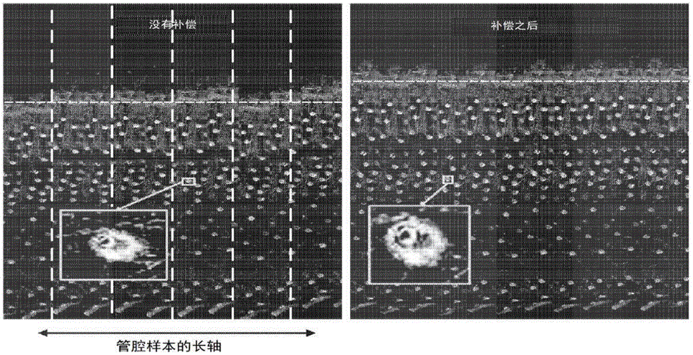
Fig. 2 illustrates an example of speckle before (left panel, inset) and after (right panel, inset) distortion compensation in accordance with embodiments disclosed herein;
FIG. 3 represents the relationship found between an image-based distortion estimate based on the speckle aspect ratio (x-axis) and the actual distortion amount calculated by measuring the aspect ratio of spherical microbeads (y-axis, where the numbers on the axes are unitless ratios), with various curve fitting methods shown superimposed on the data as part of the process for calibrating the relationship between the distortion determined using speckle and the actual distortion in the image;
FIG. 4 shows the graphical results of the analysis shown in FIG. 3, with the results of a bi-square curve fitting procedure superimposed on the data;
FIG. 5 shows the graphical results of the analysis shown in FIG. 3, with the results of the custom curve fitting routine (based on the formula of the double-squared curve fitting routine of FIG. 4) superimposed on the data;
FIG. 6 shows how one sub-stripe (red square area in the top image) is adjusted to form a corrected sub-stripe (bottom image);
FIG. 7 depicts how to create a smoother, more regular image using the distortion correction described herein by applying compensation in the axial scan direction;
FIG. 8 is a flow chart depicting an example sequence of operation of the present distortion correction algorithm; and is
FIG. 9 illustrates a computer system implementing embodiments of the methods and systems disclosed herein.
Fig. 10 illustrates an example of a process for correcting image distortion, according to some embodiments of the disclosed subject matter.
Fig. 11 illustrates an example of a process for distortion correction in accordance with some embodiments of the disclosed subject matter.
Detailed Description
In accordance with some embodiments of the disclosed subject matter, mechanisms (which may include systems, methods, and media) for image distortion correction are provided.
Laser speckle (which may be considered an unwanted artifact in some cases) may be used to advantage with various disclosed embodiments by using a laser speckle spot (which is expected to be substantially circular) to determine the amount and orientation of any distortion that may occur in an image based on the extent to which the speckle deviates from the substantially circular shape. In various embodiments, features used to compensate for distortion and features with specific local intensities (such as laser speckle) in the disclosed procedure, and these features are readily identified using the automated procedures disclosed herein. Although these features are referred to herein as laser speckle, these features may have other sources, but are still useful for identifying and correcting image distortion.
In many imaging use environments (e.g., capsule endoscopes that use illuminating lasers), undesirable distortion artifacts may occur. For example, in a 360 ° rotary capsule endoscope usage environment, the motors that rotate the illumination laser and/or the image receiving sensor may stick and/or slip. In this case, since the rotation is not successfully completed, distortion may occur in the recorded image because image reconstruction from the scan data is based on the following assumption: the data points scanned are equally spaced. That is, a series of data points are collected as the imaging probe is rotated and/or translated through the specimen. For a helical scan obtained when the probe is simultaneously rotated and translated through a luminal sample, an image of the sample is generated by assembling a series of data points into a two-or three-dimensional representation, based on the assumption that the probe is rotated and translated at a uniform rate. However, friction within the device (e.g., friction within the motor itself or between the rotating fiber and the sheath housing the fiber among various possible sources of friction) may cause stiction or slippage, resulting in uneven movement, and thus distortion in the image generated from the data stream.
Thus, the present distortion correction method and system utilizes naturally occurring speckle from the illumination laser to determine how much distortion has occurred in the scan direction and modifies the image accordingly to account for and compensate for the distortion.
FIG. 1 illustrates an example system 100 that can be used to collect data for use with embodiments of the methods and systems disclosed herein. The system 100 includes a catheter 110, the catheter 110 having an optical probe 120 disposed therein, the optical probe 120 including a reflector 130 (e.g., a ball lens or prism or mirror as shown) at an end of a waveguide 140 (e.g., an optical fiber). The light source 150 provides illumination to the waveguide 140, the waveguide 140 transmits light to the reflector 130 of the optical probe 120, and the reflector 130 directs the light beam 122 to a sample 160 (e.g., luminal tissue, such as a portion of a blood vessel or alimentary tract). Light is returned from the sample 160 along a path to the image collection and processing system 170, and the image collection and processing system 170 collects and processes the returned light to form an image or other data. The light source 150 is a coherent light source (such as a laser) that produces speckle artifacts that are used for image correction in the present procedure.
During data collection, the optical probe 120 can rotate 124 and/or translate 126 in order to collect data from a full circumferential region of the sample 160 (due to the rotation 124) as well as along the axial length of the sample 160 (due to the translation 126). The waveguide 140 may be rotated 124 and/or translated 126 within the sheath 142 before reaching the catheter 110. To facilitate rotation and translation of the optical probe 120, a rotation and translation device 180 (the device 180 may also include a rotational optical coupler) is attached to the proximal end of the catheter. The rotation and translation device 180 may include a linear motor for translating the optical probe 120 and a motor (e.g., a hollow motor) for rotating the optical probe 120. In some embodiments, instead of the catheter 110, the optical probe 120 may be housed in a capsule device swallowed by the patient, in particular for probing the alimentary tract. In various embodiments, the motor for rotating the reflector 130 may be located adjacent the distal end of the reflector 130, particularly in capsule-based embodiments. In various embodiments, the optical probe 120 may rotate at a rate of 1-30Hz, 1-100Hz, 1-1000Hz, or 1-10000Hz, and may translate at a rate of 1-10 mm/minute.
In various embodiments, components that may cause image distortion include stiction or sliding of the waveguide 140 within the sheath 142 or catheter 110 and/or stiction or sliding of components within the rotation and translation device 180 (such as a rotation or linear/translation motor). In certain embodiments, the correction procedures disclosed herein may be performed after the data is collected, for example, at a later date by processing previously stored data. In other embodiments, the correction procedure may be performed with the data collection, for example, by processing the data and storing a corrected version of the data as it is collected. In certain embodiments, the calibration procedure may be performed at substantially the same rate as the data collection, so that the processing is effectively done in real-time.
Fig. 2 shows an example of speckle before (left panel, inset) and after (right panel, inset) distortion compensation according to embodiments disclosed herein. In various embodiments, the entire image (shown uncorrected in the left panel of FIG. 2) may first be divided into small strips. For example, in some embodiments, the image may be divided into strips having a first dimension (e.g., the horizontal dimension in FIG. 2), which may be in the range of 300-500 pixels (and more specifically 400 pixels in particular embodiments), and a second, substantially orthogonal dimension, which may be determined by the dimension of the original image, e.g., the "width" of the original image; the width of the image (e.g., the vertical dimension in fig. 2) may correspond to the direction of movement (e.g., rotation), and in particular may correspond to data collected from a full rotation of the rotating imaging probe within the luminal sample, where the image is a flat representation of the tubular data set. Fig. 2 assumes a 360 ° rotation of the "helix" down within the lumen, e.g., a helical dataset produced by rotating the imaging probe while linearly advancing the probe, where the left side of each panel of fig. 2 corresponds to one end of the lumen. As a result, each "stripe" represents data from one full circumferential rotation of the imaging device (see vertical dashed lines in the left panel of fig. 2, which shows how the image is divided into a set of possible image stripes). In some embodiments, the number and size of the stripes in an image may be related to the total height of the stripes, e.g., such that each image is divided into stripes of substantially the same size.
Next, each "stripe" may be subdivided along its length (e.g., along the vertical dimension in fig. 2) into a plurality of sub-stripes or "frames". For example, each sub-strip may be substantially square, for example, in the range of 300-500 pixels "long", and more specifically 400 pixels. The number and size of the sub-strips in a strip may be related to the total length of the strip, e.g. such that each strip is divided into sub-strips of substantially the same size.
After the sub-strips are formed, each sub-strip is analyzed to obtain areas of greater or lesser illumination, e.g., to look for "bright spots" or other features indicative of laser speckle areas. In certain embodiments, speckle or "bright spots" are identified in an automated fashion using an image filtering program. In one particular embodiment, a high-pass filtering scheme may be used, for example, by taking the difference between the original image and a filtered copy of the image in which "noise" has been reduced or removed (e.g., by using an adaptive filter such as a wiener filter), which produces a resultant image in which speckle or "bright spots" are the only or dominant features.
Once one or more "hot spots" or other features in the sub-band are identified, the shape of each of those "hot spots" or features is analyzed. In some embodiments where the size of the sub-bands or frames has been selected such that at most one feature, such as a speckle or "bright spot" (see below), is contained therein, an automated procedure may be used to identify the boundaries of such features. This may be accomplished, for example, by mathematically identifying the x and/or y dimensions of any feature based on the full width at half maximum (FWHM) of the feature. The ratio of the FWHM of the horizontal (or x-dimension) and vertical (or y-dimension) dimensions of the feature (i.e., the aspect ratio) provides an indication of distortion, if any. For example, if the aspect ratio is approximately 1, this indicates little or no distortion, while aspect ratios above or below 1 indicate distortion in the image (e.g., stretching or compression in a given direction).
In some embodiments, a procedure for identifying the aspect ratio of a feature may be used that is based on computing the autocovariance of the image data (or the autocovariance of the processed image data as discussed above, where speckle, "bright spots," or other features have been emphasized). This procedure can then return feature width values for two orthogonal directions. For example, the SpeckleSize _ gray ()) function in the code provided below processes the sub-bands using autocovariance and returns feature width values for two orthogonal directions, which may take into account multiple speckles or other features within a given sub-band. Where there are two or more such features within a sub-strip, the returned feature width values in each direction take into account the dimensions of all the features in each respective direction, effectively providing an average of these dimensions. Although in some embodiments, the feature width is determined by calculating the full width at half maximum (FWHM), in the embodiments indicated by the code below, Gaussian values are used down to 0.5 and 1/e2The width in value determines the feature width. This determination is made even when the amplitude of the gaussian function is not uniform (i.e., even if the function is not normalized such that the amplitude is equal to 1.0)The feature width approach may give a better understanding of the size of the speckle dimension, which would be expected to be a good fit to the normalized data, but this procedure may produce unexpected trends.
After identifying the distortion from the aspect ratio, the sub-strips are then virtually stretched and/or compressed (i.e., "undistorted") to return each speckle, "bright spot," or other feature to a substantially circular contour, thereby creating a corrected sub-strip or frame. This analysis and distortion is repeated for each sub-band of a given band, and then the corrected sub-bands are recombined (e.g., "stitched together") in their original order to form a corrected band.
In some embodiments, the aspect ratio may be further adjusted before using this value to remove distortion in the sub-band or frame. For example, the "measured" aspect ratio may be adjusted to determine a "true" aspect ratio, which is then applied to the sub-strips or frames to provide a suitable adjustment to compensate for distortion. The adjustment of the measured aspect ratio may be performed using one of the curve fitting equations obtained in the procedures shown in fig. 3-5 and the accompanying text (see below), or using any other suitable adjustment.
In one embodiment, the dimensions of the stripes and sub-stripes may be selected such that each sub-stripe has, on average, at most one speckle, "bright spot," or other feature contained therein. By adjusting the stripe and sub-stripe dimensions to include at most one speckle or other feature, each sub-stripe may be adjusted based on a single speckle or other feature, rather than two or more features within a single sub-stripe. However, in other embodiments, the dimensions of the stripes and sub-stripes may be selected to include, on average, two, three, four, or more speckles, "bright spots," or other features. In various embodiments, the size of the sub-strip or frame is selected to be small enough such that if multiple (e.g., 2, 3, 4, or more) speckles, "bright spots," or other features are contained in a single sub-strip or frame, the features are close enough to each other to experience the same or substantially the same amount of distortion (if any) such that any correction factor applied to the sub-strip or frame has an approximately equivalent effect in bringing all of the features closer to a circular contour. If the sub-bands or frames are too large, they may encompass distorted regions as well as other undistorted regions, which will affect the determination of the correction factors and the degree to which image distortion is properly compensated. In some embodiments, the sub-strips may be processed to be square or approximately square, with a substantially equal number of pixels per dimension.
In some embodiments, the motion-based distortion may be relatively local and may be caused, for example, by a slight delay in movement when the imaging probe encounters friction or by a slight acceleration in movement when the imaging probe is released from friction (which may be referred to as intra-rotational NURD, see below). Given the local nature of the distortion, two adjacent subbands may require different amounts of correction, and a distorted given subband may be adjacent to a subband that is undistorted and does not need correction at all. Furthermore, distortion in the rotating imaging probe may occur primarily in the direction of rotation (which corresponds to the vertical dimension in fig. 2). Thus, in some embodiments, resizing (e.g., change in aspect ratio) of a given sub-strip identified based on analysis of speckle, "bright spots," or other features may be performed by changing (lengthening or shortening) the dimensions of the sub-strip only in the direction of movement of the imaging probe (e.g., the vertical dimension in fig. 2) while keeping the orthogonal dimensions fixed. The advantage of this approach is that the adjusted sub-strips can be recombined into a single strip with a uniform width.
In some embodiments, motion-based distortion and/or corrections to the image data to compensate for distortion may cause discontinuities in the data between adjacent image strips (which may be referred to as inter-rotation NURD, see below). Various procedures may be applied to the data to properly align and reconnect image strips, including the procedures described below (e.g., in conjunction with the flow diagram of FIG. 8) relating to measuring cross-correlation between adjacent strips.
Each band is segmented, analyzed/warped and recombined in a similar manner, and then the plurality of corrected bands are recombined in their original order to form a corrected image. An example of a corrected image is shown in the right panel of fig. 2. Further, the corrected image may be further used as desired.
It is contemplated that adjacent sub-bands of a strip and/or adjacent strips of an image may be cross-correlated in any desired manner such that edges of a portion of the image (e.g., a single laser speckle) are aligned to facilitate combining the corrected sub-strips and/or corrected strips in a precise manner. As a simple example, if one corrected band depicts a substantially semicircular artifact whose circumference has a known curvature, and an adjacent corrected band depicts an oppositely-opposing substantially semicircular artifact having a very similar or identical circumference, the corrected bands may be "matched" to the semicircular artifact by being "paired" or otherwise having aligned perimeters, provided that they are two portions of a unique substantially circular artifact. The corrected image may be provided in any suitable form, including various user-perceptible forms, for further processing and/or analysis. The corrected images generated using the techniques disclosed herein may be transmitted and/or presented to a user (e.g., a researcher, operator, clinician, etc.) and/or may be stored (e.g., as part of a study database or medical record associated with the subject).
To calibrate the distortion correction procedure, a series of images of different sized fluorescent beads were collected and analyzed (fig. 3). This procedure is used to confirm that naturally occurring speckle is an effective method of identifying and correcting image distortion and adjusting any deviations in the correction determined using speckle to align with the distortion identified using a reference standard, such as microbeads. The actual distortion in the image was determined based on measuring the aspect ratio of each bead, assuming that each bead is a spherical structure with an aspect ratio of 1; thus, any deviation of the bead from an aspect ratio of 1 is taken as an indication of actual distortion in the image. Image-based distortion is also estimated based on the aspect ratio of the speckles, which is also assumed to be 1. Thus, fig. 3 represents the relationship (axis is unitless) found between the speckle aspect ratio based image-based distortion estimation and the actual distortion amount calculated by measuring the aspect ratio of spherical microbeads. This relationship is used to help calibrate the software used to perform the example distortion correction operation.
In fig. 3, each circle drawn represents an image or portion of an image that uses both microbeads and speckles to determine an aspect ratio, where the calculated aspect ratio for each image is graphically represented on the x-axis based on the aspect ratio of the speckles and on the y-axis based on the aspect ratio of the microbeads. It was determined that the aspect ratios (and hence the estimated distortions) generated using the two procedures are not exactly the same, and therefore several functions were used to identify the mathematical relationship between the results obtained using the two procedures. A simple linear fit of the data produced a straight line with a slope of 1.1, while other fitting procedures produced various curves as shown in fig. 3. In addition to linear fitting, other procedures include Least Absolute Residual (LAR), bi-squared (see fig. 4), and Robust Off (this means "turn Off any Robust approximation (Robust adaptation)", i.e., a standard least squares polynomial fit, as opposed to LAR and bi-squared fits). Further, a custom curve fitting formula ("custom") is determined based on the bi-quadratic formula (see fig. 5).
Figure 4 shows the results of curve fitting the data set using the bi-squaring technique using the following parameters:
f(x)=p1*x3+p2*x2+p3*x+p4
where the coefficients (with 95% confidence limits) are:
p1=07736(0.4771,1.07)
p2=-1.865(-2.779,-0.951)
p3=2.739(1.896,3.581)
p4=-0.427(-0.6545,-0.1994)
FIG. 5 shows the results of curve fitting a data set using a custom technique using the following parameters:
f(x)=p1*x3+p2*x2+p3*x+p4
where the coefficients (with 95% confidence limits) are:
p1=1.619(1.303,1.934)
p2=-3.786(-4.759,-2.813)
p3=4.088(3.191,4.985)
p4=-0.7122(-0.9544,-0.47)
see fig. 4 for further information.
The test specimen used to generate the images of fig. 6 and 7 included a set of dried microspheres attached to the vial inner wall and imaged using a capsule-based imaging device. The size of the microspheres was 50.2 μm. + -. 0.3 μm (4K-50, standard for thermo-electroscience 3K/4K series particle counter). The dimensions are chosen such that the microspheres should be large enough to confirm the circularity of each microsphere in the image, but small enough to fit within a single imaging field of view size, i.e., 200 μm by 200 μm, although microspheres of other dimensions less than 100 μm and greater than 10 μm may also be used. The image in fig. 7 is collected at a lower magnification, thus showing a larger field of view than in fig. 6.
Fig. 6 shows how one sub-strip (the area within the dashed box on the left side of the top panel of fig. 6) is adjusted to form a corrected sub-strip (the bottom panel of fig. 6). The top panel in fig. 6 shows image strips, the left part of the top image (enclosed by the dashed box and labeled "pre-correction") being a sub-strip processed using the procedure disclosed herein to determine the degree of distortion and the correction factors for removing the distortion. The bottom panel of FIG. 6 shows the sub-strips after their aspect ratios have been adjusted based on the correction factors identified using the disclosed procedure. While horizontal stretching is the only compensation performed in this example, and thus stretching/compensation in the scan direction is used in the correction in this example, any combination of stretching or compression of the image in any direction(s) may help create a corrected sub-swath for a particular use environment. Similar patterns of bright and dark areas in the "before" and "after" areas within the red outline should be noted.
Fig. 7 depicts how the distortion correction described herein can be used to create a smoother, more regular image, not only in the rotational scan direction, but also in a secondary (e.g., axial) scan direction. The left panel shows the test or phantom image before distortion correction is applied and the right panel shows the same image after distortion correction. The vertical dimension in each panel is the rotational scan direction, while the horizontal dimension in each panel is the linear scan direction. As can be seen in the left panel image before distortion correction, many features in the image are misaligned in the horizontal direction, whereas in the right panel image after distortion correction, the features are aligned more closely from left to right. While this sample is a phantom for demonstration purposes, one of ordinary skill in the art will understand how to use the distortion correction procedures disclosed herein to help provide more accurate and useful imaging (e.g., imaging the interior of a patient's body lumen to detect and/or monitor a lesion) via the use of a laser speckle-assisted procedure.
Fig. 8 is a flow chart depicting a method 800 for distortion correction in accordance with an embodiment of the invention. At start 810, the step 812 of loading data on memory may be followed by a step 814 of segmenting the data via each rotation, followed by initializing 816 a variable i-1. The method 800 continues 818 until i > # rotates times, at which point the method 800 reaches an end 820.
The next step of the method 800 may include converting the data segment into a rotated image strip 822. Next, the method 800 may include segmenting each image slice into frames or sub-slices 824. A variable j may be initialized 826 and set to j ═ 1. The analysis of each sub-band or frame will continue 828 until j > the number of frames. For each sub-slice or frame, method 800 may include: extracting a speckle image 830 of each frame through filtering; measuring aspect ratio of speckle autocovariance 832; calculating a correction factor from the aspect ratio 834; and resizing the image in the rotational direction using the correction factor 836. The variable j is incremented 838 so that after each sub-band or frame is analyzed j +1 and control returns to step 828 to determine if j > the number of frames. The step of compensating for distortion of each sub-band or frame provides a correction for NURD (non-uniform rotational distortion) within the rotation.
When all frames of a particular image slice are analyzed (when j > number of frames at step 828), an adjustment is made to correct inter-rotation NURD, i.e., distortion between adjacent image slices. An initial step may include measuring the cross-correlation between the current and previous image strips 840; subsequent steps may include calculating phase delay values that maximize the cross-correlation 842; and a further step may include aligning 844 the current slice with the previous slice using the phase delay. Once completed, the variable i may be incremented 846 such that i ═ i +1, and control returns to step 818 to determine if i > number of revolutions. Once i is greater than the number of revolutions, the method 800 reaches an end 820.
In some embodiments, the procedures disclosed herein may be implemented using commercially available data analysis software; specific examples of such code for Matlab packages are shown below:
% speckle-based distortion correction
data_ND=[];
for s=1:hori/vert
ind=1+(s-1)*vert:s*vert;
img=data1(:,ind);
min_int=mean(min(img));
max_int=mean(max(img));
avg_int=mean(mean(img));
med_int=median(median(img));
imgf-wiener 2(img, [ 22 ]); % wiener filter
[size_x,size_y]=size(imgf);
imgf=imresize(imgf,2);
[HFWHM,VFWHM]=SpeckleSize_gray(imgf);
mNURD=VFWHM/HFWHM;
dNURD=mNURD+0.8109...
-(-451.6*exp(-0.0007511*avg_int)...
+0.9899*exp(-3.833e-06*avg_int));
rNURD ═ 1.619 ^ dNSD ^3-3.786 ^ dNSD ^2+4.088 ^ dNSD-0.7122; % customization
rmnurd ═ max ([ rmnurd 1/vert ]); % to prevent the factor from being negative
img_ND0=0imresize(data1(:,ind),[size_xround(size_y*rNURD)]);
data_ND=[data_ND,img_ND];
logdata=[int2str(i),″,...
int2str(s),″,...
int2str(min_int),″,...
int2str(max_int),″,...
int2str(avg_int),″,...
int2str(med_int),″,...
num2str(HFWHM),″,...
num2str(VFWHM),″,...
'\r\n'];
fprintf(logID,logdata);
% writing in TIF File
maxint=mean(max(img))/2;
minint=mean(min(img));
img=uint16((img-minint)/maxint*(2^16));
maxint=mean(max(img_ND))/2;
minint=mean(min(img_ND));
img_ND=uint16((img_ND-minint)/maxint*(2^16));
index=ceil(i/Num_steps);
fname=strcat(bead_folder,c,num2str(index),'-',...
num2str(s),'(',num2str(VFWHM/HFWHM),')');
imwrite(img,strcat(fname,'.GIF'),'tif');
fname=strcat(nurd_folder,c,num2str(index),'-',...
num2str(s),'(',num2str(VFWHM/HFWHM),')_ND');
imwrite(img_ND,strcat(fname,'.GIF'),'tif');
end
data1=data_ND;
if size(data1,2)<hori/2
data1=data0;
end
% background Compensation
hori_cur=size(data1,2);
hori_max=max(hori_max,hori_cur);
dummy=0;data1_min=min(data1)';
data1_temp=[data1_min(hori_cur-dummy+1:hori_cur);
data1_min;data1_min(1:dummy)];
ylower=smooth(data1_temp,200)';
ylower=ylower(dummy+1:hori_cur+dummy);
comp_BG=repmat(mean(ylower)./ylower,vert,1);
data1=data1.*comp_BG;
% cross-correlation based image realignment
data1=circshift(data1,[0preDiff]);
strip_prev=smooth(mean(data0)-mean(mean(data0)),2000);
strip_curr=smooth(mean(data1)-mean(mean(data1)),2000);
[acor,lag]=xcorr(strip_prev,strip_curr);length_acor=length(acor);
wfunc=normpdf(1:length_acor,(length_acor+1)/2,(length_acor+1)/2/16)';
acor=acor.*wfunc;[~,I]=max(acor);cofactor=(cofactor*(i-1)+I)/i;
lagDiff=lag(I)*(i>1);preDiff=lagDiff;
data1=circshift(data1,[0lagDiff]);
data0=data1;
The following is the Matlab code of the SpeckleSize _ gray () function:
function[HFWHM,VFWHM]=SpeckleSize_gray(SpeckleImg)
m ═ size (SpeckleImg, 1); % height of area
N-size (SpeckleImg, 2); % width of the region
SpeckleImg=double(SpeckleImg);
E ═ SpeckleImg (1,:); % creating an array with row 1 values
s size (xcov (e)); % size of the search autocovariance array
D ═ zeros(s); % create empty array of size s
D ═ double (D); % converting value form to double precision
for i=1:M
C=SpeckleImg(i,:);
D ═ imadd (D, xcov (C, 'coeff')); % summing the xcov arrays of all rows to D
end
H0 ═ D/max (D); % level of product achieved, H is normalized
sizeH=size(H0,2);
H=H0(floor(sizeH/2)-5:floor(sizeH/2)+5);
E1 ═ SpeckleImg (: 1); % creating an array with a value of column 1
s1 size (xcov (E1)); % size of lookup auto-covariance array
D1 ═ zeros (s 1); % create empty array of size s1
D1 ═ double (D1); % converting value form to double precision
for j=1:N
C1=SpeckleImg(:,j);
if max(C1)>0
D1 ═ D1+ xcov (C1, 'coeff'); % summing the xcov arrays of all rows to D1
end
end
V0 ═ D1/max (D1); % completed vertical product V is normalized
sizeV=size(V0);
V=V0(floor(sizeV/2)-5:floor(sizeV/2)+5);
% H and V fitting the Gaussian distribution and extracting the speckle size from the fit.
helper1=1:size(H,2);
helper2=1:size(V);
gauss1 ═ fit type ('gauss 1'); % set Gaussian curve fitting
excludlowh ═ excludedata (helper1', H', 'range', [.1,1 ]); % exclusion of noise outside of speckle
excludeLowV=excludedata(helper2',V,'range',[.1,1]);
optionsH=fitoptions(gauss1);
optionsV=fitoptions(gauss1);
optionsH.Exclude=excludeLowH;
optionsV.Exclude=excludeLowV;
[HFit,HFitStats]=fit(helper1',H',gauss1,optionsH);
[VFit,VFitStats]=fit(helper2',V,gauss1,optionsV);
HFWHM ═ (2 × (hfit.c1) × sqrt (-log (.5/(hfit.a 1))); % FWHM value (full width when fitted 0.5)
VFWHM=(2*(VFit.c1)*sqrt(-log(.5/(VFit.a1))));
(hfit.c1) × sqrt (-log ((.1353353)/(hfit.a 1))); % 1/e ^2 values (full width when fit ^ 0.135)
VeSquared=((VFit.c1)*sqrt(-log((.1353353)/(VFit.a1))));
end
Fig. 9 shows a schematic block diagram illustrating an example computer system 900, the example computer system 900 including hardware components capable of implementing embodiments of the systems and methods for identifying and correcting distortion disclosed herein, where the system 900 may include various systems and subsystems. System 900 may be a personal computer, laptop computer, workstation, computer system, device, Application Specific Integrated Circuit (ASIC), server, blade server center, server farm, etc., and may be distributed across one or more computing devices.
The system 900 may include a system bus 902, a processing unit 904, a system memory 906, storage devices 908 and 910, a communication interface 912 (e.g., a network interface), a communication link 914, a display 916 (e.g., a video screen) or other output device, and an input device 918 (e.g., a keyboard, mouse, touch screen, touch pad, etc.). The system bus 902 can communicate with the processing unit 904 and the system memory 906. Additional memory devices 908 and 910, which can include various non-transitory storage devices such as hard drives, servers, stand-alone databases, or other non-volatile storage, can also communicate with system bus 902. The system bus 902 interconnects the processing unit 904, memory devices 906, 908, 910, communication interface 912, display 916, and input device 918. In some examples, the system bus 902 can also interconnect with one or more additional ports, such as a Universal Serial Bus (USB) port, an ethernet port, or other communication mechanisms/connections.
The processing unit 904 may be a computing device and may include an Application Specific Integrated Circuit (ASIC) or other processor or microprocessor. The processing unit 904 executes a set of instructions to implement the operations of the examples disclosed herein. The processing unit may include a processing core.
Additionally or alternatively, the system 900 may access external data sources or query sources via the communication interface 912, and the communication interface 912 may communicate with the system bus 902 and the communication link 914.
In operation, the system 900 may be used to implement one or more portions of distortion correction in accordance with the present invention. According to certain examples, computer executable logic for implementing portions of distortion correction resides on the system memory 906 and one or more of the memory devices 908 and 910. Processing unit 904 executes one or more computer-executable instructions originating from system memory 906 and memory devices 908 and 910. The term "computer-readable medium" as used herein refers to one or more media that participate in providing instructions to processing unit 904 for execution.
It will thus be appreciated that computer-readable media is non-transitory and may include, for example, a plurality of discrete media operatively connected to a processing unit via one or more of a local bus or network connection.
In some embodiments, any suitable computer readable medium may be utilized to store instructions for performing the functions and/or processes described herein. For example, in some embodiments, the computer-readable medium may be transitory or non-transitory. For example, non-transitory computer readable media may include media such as: magnetic media (such as hard disks, floppy disks, etc.), optical media (such as compact disks, digital video disks, blu-ray disks, etc.), semiconductor media (such as RAM, flash memory, electrically programmable read-only memory (EPROM), electrically erasable programmable read-only memory (EEPROM), etc.), any suitable media that are not transitory or have any persistent appearance during transmission, and/or any suitable tangible media. As another example, a transitory computer-readable medium may include a signal on a network, a signal on a wire, a conductor, a fiber, a circuit, or any suitable medium that is transitory and does not have any persistent appearance during transmission, and/or any suitable intangible medium.
It should be noted that the term mechanism as used herein may encompass hardware, software, firmware, or any suitable combination thereof.
Fig. 10 illustrates an example 1000 of a process for correcting image distortion in accordance with some embodiments of the disclosed subject matter. As shown in fig. 10, at 1002, process 1000 can analyze an image segment of an image obtained from a scanning imaging device to identify speckle artifacts. At 1004, the process 1000 may determine an aspect ratio of the shape of the speckle artifact. At 1006, process 1000 may determine a correction factor for the shape of the speckle artifact based on the aspect ratio. Finally, at 1008, the process 1000 may adjust the size of the image segment based on the correction factor.
Fig. 11 illustrates an example 1100 of a process for distortion correction in accordance with some embodiments of the disclosed subject matter. As shown in fig. 11, at 1102, process 1100 can provide an image. At 1104, the process 1100 may divide the image into a plurality of substantially parallel strips, each strip extending in a first direction. At 1106, process 1100 may divide each stripe into a plurality of sub-stripes along a second direction substantially perpendicular to the first direction. At 1108, the process 1100 may analyze each of the plurality of sub-bands to locate at least one locally bright feature. At 1110, process 1100 may distort at least a portion of each sub-strip to urge the local maximum/minimum feature toward the predetermined shape, thereby creating a corrected sub-strip. At 1112, the process 1100 may reassemble the plurality of corrected sub-strips into a corrected strip. Finally, at 1114, process 1100 can reassemble the plurality of corrected strips into a corrected image.
It should be understood that the above-described steps of the processes of fig. 10 and 11 may be performed or carried out in any order or sequence that is not limited to the order or sequence shown and described in the figures. Further, some of the above-described steps of the processes of fig. 10 and 11 may be performed substantially simultaneously or in parallel, where appropriate, to reduce latency and processing time.
As used herein, the singular forms "a", "an" and "the" may include the plural forms as well, unless the context clearly indicates otherwise. It will be further understood that the terms "comprises" and/or "comprising," when used herein, specify the presence of stated features, steps, operations, elements, and/or components, but do not preclude the presence or addition of one or more other features, steps, operations, elements, components, and/or groups thereof.
As used herein, the term "and/or" includes any and all combinations of one or more of the associated listed items.
It will be understood that when an element is referred to as being "on" …, "attached" to, "connected" to, "coupled" to "contacting," etc., another element may be directly on, attached to, connected to, coupled to, or contacting the other element or intervening elements may also be present. In contrast, when an element is referred to as being, for example, "directly on …," "directly attached," "directly connected," "directly coupled," or "directly contacting" another element, there are no intervening elements present.
As shown, spatially relative terms such as "under", "below", "lower", "over", "upper", and the like may be used herein to describe the relationship of an element or feature to other element(s) or features for ease of description. It will be understood that the spatially relative terms may encompass different orientations of the device in use or operation in addition to the orientation depicted in the figures. For example, if the device in the figures is turned over, elements described as "below" or "beneath" or "on" other elements or features would then be oriented "above" the other elements or features.
The invention comprises, consists of or consists essentially of the features described herein in any combination.
Thus, while the invention has been described above in connection with specific embodiments and examples, the invention is not necessarily so limited, and many other embodiments, examples, uses, modifications, and departures from the described embodiments, examples, and uses are intended to be encompassed by the appended claims.
Claims (34)
Applications Claiming Priority (3)
| Application Number | Priority Date | Filing Date | Title |
|---|---|---|---|
| US201962797548P | 2019-01-28 | 2019-01-28 | |
| US62/797,548 | 2019-01-28 | ||
| PCT/US2020/015153 WO2020159844A1 (en) | 2019-01-28 | 2020-01-27 | Speckle-based image distortion correction for laser scanning microscopy |
Publications (2)
| Publication Number | Publication Date |
|---|---|
| CN113678054A true CN113678054A (en) | 2021-11-19 |
| CN113678054B CN113678054B (en) | 2024-11-15 |
Family
ID=71840601
Family Applications (1)
| Application Number | Title | Priority Date | Filing Date |
|---|---|---|---|
| CN202080025783.2A Expired - Fee Related CN113678054B (en) | 2019-01-28 | 2020-01-27 | Speckle-based image distortion correction for laser scanning microscopy |
Country Status (6)
| Country | Link |
|---|---|
| US (2) | US11986266B2 (en) |
| EP (3) | EP3918411B1 (en) |
| JP (2) | JP7529676B2 (en) |
| CN (1) | CN113678054B (en) |
| IL (1) | IL285124A (en) |
| WO (1) | WO2020159844A1 (en) |
Families Citing this family (1)
| Publication number | Priority date | Publication date | Assignee | Title |
|---|---|---|---|---|
| JP7413512B2 (en) | 2019-08-27 | 2024-01-15 | ザ ジェネラル ホスピタル コーポレイション | Systems and methods for high-resolution high-speed capsule endoscopy |
Citations (6)
| Publication number | Priority date | Publication date | Assignee | Title |
|---|---|---|---|---|
| CN102119326A (en) * | 2008-08-13 | 2011-07-06 | 皇家飞利浦电子股份有限公司 | Measuring and correcting lens distortion in a multispot scanning device |
| US20150216415A1 (en) * | 2014-01-31 | 2015-08-06 | The General Hospital Corporation | Method and apparatus for performing multidimensional velocity measurements using amplitude and phase in optical interferometry |
| US20170143213A1 (en) * | 2013-06-19 | 2017-05-25 | The General Hospital Corporation | Apparatus, devices and methods for obtaining omnidirectional viewing by a catheter |
| CN107260195A (en) * | 2016-02-29 | 2017-10-20 | 通用电气公司 | The system and method that artifact for Computed tomography is removed |
| CN107735015A (en) * | 2015-05-07 | 2018-02-23 | 诺瓦达克技术公司 | The method and system being imaged using the laser speckle for tissue of color image sensor |
| CN108573468A (en) * | 2017-03-07 | 2018-09-25 | 伊鲁米那股份有限公司 | Optical distortion correction for imaged samples |
Family Cites Families (10)
| Publication number | Priority date | Publication date | Assignee | Title |
|---|---|---|---|---|
| US4792231A (en) | 1987-06-25 | 1988-12-20 | Fried David L | Laser speckle imaging |
| EP1533751B1 (en) * | 2003-11-10 | 2008-02-13 | Leica Microsystems CMS GmbH | A method for correcting distortions in multi-focus image stacks |
| US10534129B2 (en) * | 2007-03-30 | 2020-01-14 | The General Hospital Corporation | System and method providing intracoronary laser speckle imaging for the detection of vulnerable plaque |
| CN101784227B (en) * | 2007-07-06 | 2013-12-04 | 工业研究有限公司 | Laser speckle imaging systems and methods |
| US7878651B2 (en) | 2007-12-26 | 2011-02-01 | Carl Zeiss Meditec, Inc. | Refractive prescription using optical coherence tomography |
| JP5832523B2 (en) | 2010-04-29 | 2015-12-16 | マサチューセッツ インスティテュート オブ テクノロジー | Method and apparatus for motion correction and image improvement for optical coherence tomography |
| US9226673B2 (en) * | 2011-01-10 | 2016-01-05 | East Carolina University | Methods, systems and computer program products for non-invasive determination of blood flow distribution using speckle imaging techniques and hemodynamic modeling |
| EP3748338A1 (en) | 2013-06-19 | 2020-12-09 | The General Hospital Corporation | Omni-directional viewing apparatus |
| JP2020064564A (en) * | 2018-10-19 | 2020-04-23 | 株式会社アスカネット | Learning server, learning system, and additional learning program |
| US10992902B2 (en) * | 2019-03-21 | 2021-04-27 | Disney Enterprises, Inc. | Aspect ratio conversion with machine learning |
-
2020
- 2020-01-27 EP EP20748254.8A patent/EP3918411B1/en active Active
- 2020-01-27 CN CN202080025783.2A patent/CN113678054B/en not_active Expired - Fee Related
- 2020-01-27 EP EP23219093.4A patent/EP4321922B1/en active Active
- 2020-01-27 US US17/310,263 patent/US11986266B2/en active Active
- 2020-01-27 JP JP2021543361A patent/JP7529676B2/en active Active
- 2020-01-27 WO PCT/US2020/015153 patent/WO2020159844A1/en not_active Ceased
- 2020-01-27 EP EP25195390.7A patent/EP4620386A3/en active Pending
-
2021
- 2021-07-25 IL IL285124A patent/IL285124A/en unknown
-
2024
- 2024-04-15 US US18/635,232 patent/US12495972B2/en active Active
- 2024-07-24 JP JP2024118363A patent/JP7737519B2/en active Active
Patent Citations (6)
| Publication number | Priority date | Publication date | Assignee | Title |
|---|---|---|---|---|
| CN102119326A (en) * | 2008-08-13 | 2011-07-06 | 皇家飞利浦电子股份有限公司 | Measuring and correcting lens distortion in a multispot scanning device |
| US20170143213A1 (en) * | 2013-06-19 | 2017-05-25 | The General Hospital Corporation | Apparatus, devices and methods for obtaining omnidirectional viewing by a catheter |
| US20150216415A1 (en) * | 2014-01-31 | 2015-08-06 | The General Hospital Corporation | Method and apparatus for performing multidimensional velocity measurements using amplitude and phase in optical interferometry |
| CN107735015A (en) * | 2015-05-07 | 2018-02-23 | 诺瓦达克技术公司 | The method and system being imaged using the laser speckle for tissue of color image sensor |
| CN107260195A (en) * | 2016-02-29 | 2017-10-20 | 通用电气公司 | The system and method that artifact for Computed tomography is removed |
| CN108573468A (en) * | 2017-03-07 | 2018-09-25 | 伊鲁米那股份有限公司 | Optical distortion correction for imaged samples |
Also Published As
| Publication number | Publication date |
|---|---|
| US20220054013A1 (en) | 2022-02-24 |
| EP4620386A2 (en) | 2025-09-24 |
| EP4321922B1 (en) | 2025-10-15 |
| US11986266B2 (en) | 2024-05-21 |
| JP7737519B2 (en) | 2025-09-10 |
| EP4321922A2 (en) | 2024-02-14 |
| JP7529676B2 (en) | 2024-08-06 |
| EP4321922A3 (en) | 2024-07-17 |
| EP3918411B1 (en) | 2024-01-03 |
| EP3918411A4 (en) | 2022-11-16 |
| EP4620386A3 (en) | 2025-11-19 |
| US12495972B2 (en) | 2025-12-16 |
| CN113678054B (en) | 2024-11-15 |
| JP2024153735A (en) | 2024-10-29 |
| EP3918411A1 (en) | 2021-12-08 |
| US20240268672A1 (en) | 2024-08-15 |
| WO2020159844A1 (en) | 2020-08-06 |
| IL285124A (en) | 2021-09-30 |
| JP2022523061A (en) | 2022-04-21 |
Similar Documents
| Publication | Publication Date | Title |
|---|---|---|
| EP3625759B1 (en) | Reducing noise in an image | |
| US10206585B2 (en) | Automatic calibration systems and methods of use | |
| US8395781B2 (en) | Automatic calibration systems and methods of use | |
| US10359271B2 (en) | System and method for tissue differentiation in imaging | |
| CA2949264C (en) | Method and system of determining probe position in surgical site | |
| US20240081650A1 (en) | Optical coherence tomography scanning system and methods | |
| KR101783964B1 (en) | Tomography apparatus and method for reconstructing a tomography image thereof | |
| JP7737519B2 (en) | Speckle-based image distortion correction for laser scanning microscopy | |
| CN104285240B (en) | The suppression to external high contrast object based on stereoscopic X-ray pipe | |
| KR102427573B1 (en) | Method of medical image registration | |
| KR20200090102A (en) | X-ray imaging apparatus and control method for the same | |
| Yang et al. | Quantitative measurement of tympanic membrane structure and symmetry with optical coherence tomography in normal human subjects | |
| JP7595405B2 (en) | Medical image processing device, OCT device, and medical image processing program | |
| Guan et al. | Correction of Non‐Uniform Rotational Distortion in the Proximally Controlled Endoscopic OCTA | |
| JP2025526312A (en) | Calibration of an imaging system combining optical coherence tomography and visualization modules | |
| CN121001642A (en) | Eye retinal examination equipment |
Legal Events
| Date | Code | Title | Description |
|---|---|---|---|
| PB01 | Publication | ||
| PB01 | Publication | ||
| SE01 | Entry into force of request for substantive examination | ||
| SE01 | Entry into force of request for substantive examination | ||
| GR01 | Patent grant | ||
| GR01 | Patent grant | ||
| CF01 | Termination of patent right due to non-payment of annual fee | ||
| CF01 | Termination of patent right due to non-payment of annual fee |
Granted publication date: 20241115 |