Gas circulation system with gas seal access cap and valve seal access cap for robot assisted surgery
Cross Reference to Related Applications
The present application claims priority rights to U.S. provisional patent application serial No. 62/823,848 filed on 26.3.2019, U.S. provisional patent application serial No. 62/876,141 filed on 19.7.2019, U.S. provisional patent application serial No. 62/925,424 filed on 24.10.10.2019, and U.S. patent application serial No. 16/829,694 filed on 25.3.2020, the disclosures of which are incorporated herein by reference in their entireties.
Background
1. Field of the invention
The present invention relates to endoscopic surgery and, more particularly, to a surgical gas circulation system having a gas seal access cap and a valve seal access cap for use during robot-assisted laparoscopic surgery.
2.Description of the related Art
Laparoscopic or "minimally invasive" surgical approaches are becoming increasingly common in the performance of procedures such as cholecystectomy, appendectomy, hernia repair, and nephrectomy. Benefits of such surgery include reduced trauma to the patient, reduced chances of infection, and reduced recovery time. Such procedures performed in the abdominal (peritoneal) cavity are typically performed through a device called a trocar or cannula, which facilitates the introduction of laparoscopic instruments into the abdominal cavity of the patient.
In addition, such procedures typically involve filling or "inflating" the abdominal cavity with a pressurized fluid, such as carbon dioxide, to create a surgical space known as pneumoperitoneum. Insufflation may be performed through a surgical access device, such as a trocar, equipped to deliver an insufflation fluid, or through a separate insufflation device, such as an insufflation (pneumo) needle. It is desirable to introduce surgical instruments into the pneumoperitoneum without substantial loss of insufflation gas in order to maintain the pneumoperitoneum.
During a typical laparoscopic procedure, the surgeon makes three to four small incisions, typically no larger than about twelve millimeters each, which are typically formed by the surgical access device itself through the use of a separate insert or obturator placed therein. After insertion, the obturator is removed and the trocar allows entry of instruments to be inserted into the abdominal cavity. Typical trocars provide a path for inflating the abdominal cavity so that the surgeon has an open interior space in which to work.
The trocar must also provide a way to maintain intraluminal pressure by sealing between the trocar and the surgical instrument being used while still allowing at least minimal freedom of movement of the surgical instrument. Such instruments may include, for example, scissors, grasping and occluding instruments, cauterizing units, cameras, light sources, and other surgical instruments. A sealing element or mechanism is typically provided on the trocar to prevent the insufflation gas from escaping from the abdominal cavity. These sealing mechanisms typically include a duckbill valve made of a relatively flexible material to seal against the outer surface of a surgical instrument passing through the trocar.
SurgiQuest, inc. of ConMed Corporation has developed a unique gas-sealed surgical access device that allows ready access to a filled surgical cavity without the use of conventional mechanical valve seals, as described, for example, in U.S. patent No. 7,854,724. These devices are made up of several nested parts including an inner tubular body portion and a coaxial outer tubular body portion. The inner tubular body portion defines a central lumen for introducing conventional laparoscopic surgical instruments into the abdominal cavity of a patient, and the outer tubular body portion defines an annular lumen surrounding the inner tubular body portion for delivering an insufflation gas to the abdominal cavity of the patient and for facilitating periodic sensing of abdominal pressure.
Robot-assisted minimally invasive surgery is also becoming more common. One well known system for performing these procedures is known as the Da Vinci robotic Surgical system, manufactured and sold by intutive Surgical, inc. The Da Vinci system utilizes a proprietary trocar or cannula that is adapted and configured to receive a robotic instrument and be engaged by a robotic arm. A proprietary Da Vinci cannula has a proximal housing that forms a bowl for receiving components such as a hermetic seal assembly, as disclosed in, for example, U.S. patent No. 10,463,395. The Da Vinci hermetic seal assembly utilizes a mechanical seal to seal around the outer surface of the surgical instrument passing through the cannula and prevents the inflation gas from escaping from the abdominal cavity.
It is believed to be beneficial to provide a sealing assembly for use with a Da Vinci cannula that allows immediate access to an inflated surgical cavity without the use of a mechanical sealing assembly. Indeed, a recent example of such a pneumatic seal assembly is disclosed in commonly assigned U.S. patent application publication No. 2018/0256207. The present invention provides an improvement over this early gas-tight access device, which is described in detail below, along with other novel devices and systems.
Disclosure of Invention
The present invention relates to a new and useful gas circulation system for performing robot-assisted surgery in an operating cavity of a patient. The system includes a multi-lumen tube set having a double lumen portion with a pressurized gas line and a return gas line for facilitating gas recirculation relative to the surgical cavity of the patient, and a single lumen portion with a gas supply and sensing line for delivering a filling gas to the abdominal cavity of the patient and for periodically sensing the pressure within the surgical cavity of the patient.
The system also includes a valve seal access cover adapted and configured for cooperative receipt within the proximal bowl portion of the first robotic cannula and having an inlet pathway for communication with the gas supply and sensing lines of the tube set, and a gas seal access cover adapted and configured for cooperative receipt within the proximal bowl portion of the second robotic cannula and having an inlet pathway for communication with the pressurized gas line of the tube set and an outlet pathway for communication with the return gas line of the tube set.
The valve seal access cover includes an outer housing portion and an inner body portion, and an annular channel is formed between the outer housing portion and the inner body portion in communication with the inlet path. An inner O-ring seals an annular passage between the outer housing portion and the inner housing portion to prevent gas leakage.
The outer housing portion includes a pair of diametrically opposed flexible clips adapted and configured to releasably latch to the proximal bowl portion of the first robotic cannula. An outer O-ring is positioned between the outer housing portion and the proximal bowl portion of the first robotic cannula to provide frictional engagement and prevent gas leakage therebetween.
The valve seal enters the inner body portion of the cap supporting the primary and secondary valves. The primary valve is a circular diaphragm valve and the secondary valve is a duckbill valve. The primary valve is located proximal to the secondary valve. A sound attenuating foam material is positioned within the valve seal access cap, proximal to the primary valve, for reducing sound levels and helping to hold the primary and secondary valves in place during instrument insertion, removal, and manipulation.
The cover engages the proximal end of the outer housing portion to secure the inner body portion within the outer housing portion and provide safety during instrument insertion, removal and manipulation. The closure further secures the inner body portion, the sound attenuating foam material, the primary valve, and the secondary valve within the outer housing portion relative to the inner body portion.
Preferably, the inlet pathway is formed with the outer housing portion and a luer-type connector is operatively associated therewith for communication with the gas supply and sensing lines of the tube set. The luer-type connector is selectively sized to achieve a desired amount of airflow into the inlet path.
The distal end surface of the inner body portion compressively engages against the inner distal surface of the inwardly tapered distal wall of the outer housing portion to close the annular channel. In one embodiment of the invention, the annular channel communicates with the proximal bowl portion of the first robotic cannula through a plurality of circumferentially spaced apart holes formed in an inwardly tapered distal wall of the outer housing portion. The plurality of apertures may be elliptical and extend radially outward from a central axis of the outer housing portion, or the plurality of apertures may extend generally tangentially relative to the central axis of the outer housing portion. The holes may also be triangular and extend radially outward from a central axis of the outer housing portion. Those skilled in the art will readily appreciate that the number and/or size of the apertures may be selected to provide a desired airflow.
In another embodiment of the invention, the annular channel communicates with the proximal bowl portion of the first robotic cannula through an annular aperture defined between the inwardly tapered distal wall of the inner body portion and the inwardly tapered distal wall of the outer housing portion.
The gas seal access cover includes a main housing portion defining an internal cavity supporting an annular jet assembly for receiving pressurized gas from the inlet path and for creating a gas seal zone within the second robotic cannula to maintain a stable pressure within the surgical cavity of the patient. The sound attenuating foam material is positioned within the gas seal access cover, proximal to the annular jet assembly. A cover is engaged with the proximal end of the outer housing portion to secure the annular jetting assembly and the sound attenuating foam material within the main housing portion.
In addition, the main housing portion includes an integrally formed set of circumferentially spaced vanes for directing gas from the gas seal zone to the outlet path of the gas seal into the cover. A set of circumferentially spaced blades extend distally to form a tubular extension extending into the proximal bowl portion of the second robotic cannula.
An external O-ring is positioned between the main housing portion of the gas seal access cover and the proximal bowl portion of the second robotic cannula. The inlet and outlet paths of the gas seal access cover communicate with a manifold associated with a bullseye connector fitting for communicating with the pressurized gas line and the return gas line of the tubing set. The bullseye connector fitting has a plurality of circumferentially spaced apart radially outwardly extending engagement lugs formed thereon.
In one embodiment of the invention, the bullseye connector fitting is a dual lumen bullseye connector fitting for communicating with the pressurized gas line and the return gas line of the tubing set. In another embodiment, the bullseye connector fitting is a three lumen bullseye connector fitting for communicating with the pressurized gas line and the return gas line of the tubing set, but not with the gas supply and sensing lines of the tubing set.
In one embodiment of the invention, the double lumen portion of the tube set includes a coupling having a circumferentially disposed bayonet-type fastening channel formed therein for mechanically engaging with an engagement lug of a bullseye connector fitting. In another embodiment of the invention, the double lumen portion of the tubing set includes a coupling having a helically arranged bayonet-type fastening channel formed therein for mechanically engaging with an engagement lug of a bullseye connector fitting.
In one embodiment of the invention, the main outer housing portion of the gas tight access cover includes a pair of diametrically opposed flexible clamps adapted and configured to releasably latch to the proximal bowl portion of the second robotic cannula. In another embodiment of the present invention, the main outer housing portion of the gas-tight access lid includes a compressible annular skirt adapted and configured to releasably latch to the proximal bowl portion of the second robotic cannula. Alternatively, the proximal bowl portion of the second robotic cannula includes a movable compressible annular skirt adapted and configured to releasably latch to the main outer housing portion of the gas seal access cover.
In another embodiment of the present invention, the main outer housing portion of the gas sealing access cover includes a spring biased hinged snap adapted and configured to releasably latch to the proximal bowl portion of the second robotic cannula. In another embodiment of the invention, the main outer housing portion of the gas-tight access lid comprises a magnetic skirt adapted to be releasably secured to the proximal bowl portion of the second robot sleeve.
In one embodiment of the invention, the triple lumen bullseye connector fitting is adapted and configured to communicate with a triple lumen bullseye coupling associated with a distal end of a double lumen portion of a tubing set. Additionally, a triple lumen bullnose plug is provided for engagement with the triple lumen bullnose coupling.
In an embodiment of the invention, the second robotic cannula has an elongated tubular body portion extending distally from a proximal bowl portion thereof, the elongated tubular body portion including a plurality of circumferentially spaced apart longitudinal beads on an inner surface thereof for accommodating airflow around a surgical instrument extending through the tubular body portion. In another embodiment of the present invention, the second robotic cannula has an elongated tubular body portion extending distally from a proximal bowl portion thereof, the elongated tubular body portion including a plurality of circumferentially spaced apart longitudinal channels in an inner surface thereof for accommodating airflow around a surgical instrument extending through the tubular body portion. In yet another embodiment of the present invention, the second robotic cannula has an elongated tubular body portion extending distally from a proximal bowl portion thereof, the elongated tubular body portion including a helical bead on an inner surface thereof for accommodating airflow around a surgical instrument extending through the tubular body portion.
These and other features of the gas circulation system of the present invention will become more readily apparent to those having ordinary skill in the art to which the present invention pertains from the following detailed description of the preferred embodiments, which is to be read in connection with the accompanying drawings.
Drawings
In order that those skilled in the art will readily understand how to make and use the gas circulation system of the present invention without undue experimentation, preferred embodiments thereof will be described in detail below with reference to the accompanying drawings, wherein:
FIG. 1 is a perspective view of the gas circulation system of the present invention in use during performance of a robot-assisted laparoscopic surgical procedure, wherein the system includes a multi-lumen filter tube set having a dual lumen portion connected to a gas-tight access cap that is removably engaged with a first robotic cannula and a valve-tight access cap that is removably engaged with a second robotic cannula;
FIG. 2 is a perspective view of the multi-lumen filter tube set shown in FIG. 1, along with a gas-tight access cover removably engaged with a first robotic cannula and a valve-tight access cover removably engaged with a second robotic cannula;
FIG. 3 is a perspective view of the valve seal access cover of the present invention removably engaged within the proximal housing of the robotic cannula;
FIG. 4 is a perspective view of the valve seal access cover of the present invention separated from the proximal housing of the robotic cannula;
FIG. 5 is an enlarged fragmentary perspective view taken from FIG. 4 of one of the diametrically opposed flexible clamps associated with the valve seal access cover for releasably latching the flange of the proximal housing to the robotic cannula;
FIG. 6 is an exploded perspective view of the valve seal access cap of the present invention with portions separated for ease of illustration;
FIG. 7 is an enlarged fragmentary perspective view of the luer connector taken from FIG. 6 for connecting the valve seal access cap to the single lumen of the filter tube set;
fig. 8 is a cross-sectional view taken along line 8-8 of fig. 3 with the luer connector attached to the luer fitting of the valve seal access cap;
FIG. 9 is a cross-sectional view taken along line 9-9 of FIG. 6, showing the distal portion of the valve seal entering the cap;
FIG. 10 is a cross-sectional view taken along line 10-10 of FIG. 6, showing a set of elliptical shaped fill holes formed in the distal portion of the valve seal access cap;
FIG. 11 shows a set of triangular shaped fill apertures formed in the distal portion of the valve seal access cap;
FIG. 12 shows another set of elliptical shaped fill holes formed in the distal portion of the valve seal access cap;
FIG. 13 shows yet another set of elliptical shaped fill apertures formed in the distal portion of the valve seal access cap;
FIG. 14 shows an annular filling gap formed in the distal portion of the valve seal access cover;
FIG. 15 is a perspective view of the gas sealing access cap of the present invention engaged within a robotic cannula, along with an obturator for gaining initial access to the patient's abdominal cavity;
FIG. 16 is a perspective view of the gas seal access cover of the present invention removably engaged within the proximal housing of the robotic cannula;
FIG. 17 is a perspective view of the gas seal access cover of the present invention separated from the proximal housing of the robotic cannula;
FIG. 18 is an exploded perspective view of the gas seal access cover of the present invention with portions separated for ease of illustration;
FIG. 19 is a cross-sectional view taken along line 19-19 of FIG. 18 showing the integrally formed internal structure of the housing with the gas seal entering the cap;
FIG. 20 is an exploded perspective view of another embodiment of the gas seal access cover of the present invention with portions separated for ease of illustration;
FIG. 21 is an enlarged plan view of the bullseye connector of the gas seal access cover of FIG. 20;
FIG. 22 is a perspective view of a multi-lumen filter tube set of the present invention with the double lumen portion of the tube set having a triple lumen connector for coupling with a gas sealing access cap of the present invention;
FIG. 23 is a perspective view of a dual lumen connector for coupling with the gas sealing access cap of the present invention, the dual lumen connector including a bayonet-type coupling feature;
FIG. 24 is a perspective view of the dual lumen connector of FIG. 23 associated with the dual lumen portion of the filter tubing set of the present invention and coupled to the dual lumen fitting of the gas seal access cap of the present invention;
FIGS. 25 and 26 are enlarged fragmentary views taken from FIG. 24 showing the engagement of the bayonet channels of the dual lumen connector with the lugs on the fitment of the gas seal access cap;
FIG. 27 is a perspective view of another dual lumen connector for coupling with the gas sealing access cap of the present invention, the dual lumen connector including another bayonet-type coupling feature;
FIG. 28 is a perspective view of the dual lumen connector of FIG. 27 associated with the dual lumen portion of the filter tubing set of the present invention and coupled to the dual lumen fitting of the gas seal access cap of the present invention;
FIGS. 29 and 30 are enlarged fragmentary views showing the engagement of the bayonet channels of the dual lumen connector of FIG. 27 with the lugs on the fitment of the gas seal access cap as shown in FIG. 28;
FIG. 31 is a perspective view of the gas sealing access cover of the present invention having a compressible skirt for removably engaging the access cover to the proximal housing of the robotic cannula;
FIG. 32 is an exploded perspective view of the gas seal access cover of FIG. 31 with parts separated for ease of illustration;
FIG. 33 is a cross-sectional view taken along line 33-33 of FIG. 31;
FIG. 34 is a cross-sectional view taken along line 34-34 of FIG. 31;
FIG. 35 is a top plan view of the gas-sealed access port of FIG. 32, showing the manner in which the compressible skirt is released from engagement with the proximal housing of the robotic cannula;
FIG. 36 is a perspective view of the gas seal access cover shown in FIG. 31 separated from the proximal housing of the robotic cannula;
FIG. 37 is a perspective view of a gas sealing access cover of the present invention having a spring biased snap for removably engaging the access cover to a proximal housing of a robotic cannula;
FIG. 38 is a perspective view of the gas seal access cover shown in FIG. 37 separated from the proximal housing of the robotic cannula;
FIG. 39 is an enlarged partial view of the hinge of the spring-biased snap of the gas seal access cover shown in FIG. 37;
FIG. 40 is a cross-sectional view taken along line 40-40 of FIG. 37;
FIG. 41 is a perspective view of the gas sealing access cover of the present invention having a magnetic skirt for removably engaging the access cover to the proximal housing of the robotic cannula;
FIG. 42 is a cross-sectional view taken along line 42-42 of FIG. 41;
FIG. 43 is an exploded perspective view of the gas seal access cover of FIG. 41 with parts separated for ease of illustration;
FIG. 44 is a perspective view of the gas sealing access cap of the present invention having an axially movable inverted compressible skirt for detachably engaging the access cap to the proximal housing of the robotic cannula;
FIG. 45 is an exploded perspective view of the gas seal access cover of FIG. 44 with parts separated for ease of illustration;
FIG. 46 is a cross-sectional view taken along line 46-46 of FIG. 44;
FIG. 47 is a perspective view of a bullseye connector plug for engaging a triple lumen connector associated with the distal end of a double lumen portion of a filter tubing set of the present invention;
FIG. 48 is a side elevational view of a conventional Da Vinci Xi robot cannula having a tubular body portion with an inner diameter sized to receive a shaft of a robotic surgical instrument;
FIG. 49 is a perspective view of a distal end portion of a tubular body of a modified robotic cannula having an expanded inner diameter with a plurality of circumferentially spaced elongate beads for creating an internal flow passage for gas;
FIG. 50 is a perspective view of a distal end portion of a tubular body of a modified robotic cannula having an expanded inner diameter with a plurality of circumferentially spaced apart elongate channels formed in an inner surface of the tubular body for airflow; and is
Fig. 51 and 52 are cross-sectional views of a tubular body of a modified robot sleeve having a spiral bead formed on an inner surface thereof, thereby forming a spiral flow path for gas.
Detailed Description
Referring now to the drawings, in which like reference numerals identify like structural elements and features of the present invention, there is shown in FIG. 1 a gas circulation system for performing endoscopic surgery in a surgical cavity of a patient, and more particularly for performing robot-assisted laparoscopic surgery in the abdominal cavity of a patient, which is constructed in accordance with a preferred embodiment of the present disclosure and is designated generally by the reference numeral 10.
The gas circulation system 10 of the present invention is specifically designed to cooperate with a programmable multi-mode gas delivery system 12. Gas delivery system 12 is of the type described in commonly assigned U.S. patent No. 9,375,539, the disclosure of which is incorporated herein by reference in its entirety. Gas delivery system 12 includes a graphical user interface 14 for setting operating parameters and a pump 16 for facilitating recirculation of pressurized gas relative to a surgical cavity of a patient. Gas delivery system 12 is connected to a surgical gas source 18 for delivering an inflation gas to a surgical cavity of a patient.
Briefly, the gas circulation system 10 includes a multi-lumen filter tube set 20 having a double lumen portion 22 and a single lumen portion 24. The double lumen portion 22 of the tube set 20 is operatively connected to a gas seal access cover 26 associated with a first robotic cannula 28. The single lumen portion 24 of the tubing set 20 is operatively connected to a valve seal access cover 30 associated with a second robotic cannula 32. Each of these components of the gas circulation system 10 and variations thereof will be described in more detail below.
Referring to fig. 2, the double lumen portion 22 of the tubing set 20 has a pressurized gas line 34 and a return gas line 36 for facilitating gas recirculation with respect to the surgical cavity of the patient and for facilitating evacuation of smoke-laden gas resulting from the electrocautery task or the like from the surgical cavity. The single lumen portion 24 of the tubing set 20 defines a gas supply and sensing line 38 having two distinct functions. It facilitates the delivery of inflation gas to the surgical cavity of the patient, and it also facilitates the periodic sensing of pressure within the surgical cavity of the patient.
The tube set 20 is operatively associated with a multi-path cartridge assembly 40. More specifically, the gas lines of tube set 20 extend from a fitting 42 on an end cap 44 of filter cartridge assembly 40. Filter cartridge assemblies of this type are disclosed, for example, in commonly assigned U.S. patent No. 9,067,030, the disclosure of which is incorporated herein by reference in its entirety. Filter cartridge assembly 40 is preferably designed for a single use and thereafter is disposable. Which is specifically designed to cooperate with the multi-mode gas delivery system 12 shown in fig. 1.
Although not shown here, the filter cartridge assembly 40 includes a first filtered flow path in communication with the pressurized gas line 34 of the double lumen portion 22 of the tube set 20, a second filtered flow path in communication with the return gas line 36 of the double lumen portion 22 of the tube set 20, and a third filtered flow path in communication with the gas supply and sensing line 38 of the single lumen portion 24 of the tube set 20.
As shown in fig. 2, the single lumen portion 24 of the tubing set 20 includes an enlarged luer-type connector fitting 46 for coupling with the valve seal access cover 30. The enlarged luer-type connector fitting 46 will be discussed in more detail below with reference to fig. 7 and 8. The double lumen portion 22 of the tubing set 20 includes a multi-lumen connector fitting 48 for coupling with the gas-tight access cover portion 26. As described in more detail below, the present disclosure describes several different embodiments of a multi-lumen connector fitting 48 for a dual lumen portion 22 of a tubing set 20.
Referring now to fig. 3-8, the valve seal access cover 30 of the gas circulation system 10 is adapted and configured for cooperative receipt within a proximal bowl portion 50 of the robot sleeve 32 that also includes an elongated tubular body portion 52. The valve seal access cover 30 has an inlet path 54 for communicating with the gas supply and sensing lines 38 of the tube set 20. More specifically, as explained in more detail below, the inlet path 54 is a luer-type connector that cooperates with the luer-type connector fitting 46 on the distal end of the gas supply and sensing line 38.
As best seen in fig. 6 and 8, the valve seal access cover 30 includes an elongated, generally cylindrical outer housing portion 56 and an elongated, generally cylindrical inner body portion 58 sized and configured to nest within the outer housing portion 56. An annular flow passage 60 is advantageously formed between the outer housing portion 56 and the inner body portion 58 in communication with the inlet path 54. An internal O-ring 62 seals annular passage 60 between outer housing portion 56 and inner housing portion 58 to provide a frictional engagement and prevent gas leakage therebetween.
The outer housing portion 56 of the valve seal access cover 30 includes a pair of diametrically opposed flexible clips 64a, 64b adapted and configured to releasably latch to an upper annular flange 66 of the proximal bowl portion 50 of the robotic cannula 32. As best seen in fig. 5, by way of example, the flexible clamp 64a includes an upper portion 65 that can be easily flexed inwardly to release a lower clamp portion 67. The opposing flexible clamp 64b is similarly constructed. An outer O-ring 68 surrounds the periphery of the outer housing portion 56 such that it is positioned between the outer housing portion 56 and the inner wall of the proximal bowl portion 50 of the robot sleeve 32 to provide a frictional engagement and prevent gas leakage therebetween.
The inner body portion 58 of the valve seal access cap 30 supports a primary valve 70 and a secondary valve 72. Preferably, the primary valve 70 is a circular diaphragm valve and the secondary valve 72 is a duckbill valve. Other types of mechanical valve seals known in the art may also be used. The primary valve 70 is nested within and proximal to the secondary valve 72. A sound attenuating disc 74 made of foam material is positioned within the valve seal access cap 30, proximal to the primary valve 70, for reducing sound levels and helping to hold the primary valve 70 and the secondary valve 72 in place during instrument insertion, removal, and manipulation.
A cover 76 engages the proximal end of the outer housing portion 56 to secure the inner body portion 58 within the outer housing portion 56 and provide safety during instrument insertion, removal and manipulation. The cap 76 defines an access passage or port 78 into the cap 30 through which surgical instruments and the like are introduced into the cannula 32. The cover 76 may be mechanically attached to the outer housing portion 56 by a clamp or tab, or it may be heat welded, spin welded, or glued in place. The cap 76 further secures the inner body portion 58, the sound attenuating disc 74, the primary valve 70 and the secondary valve 72 within the outer housing portion 56 relative to the inner body portion 58.
Referring now to fig. 7 and 8, preferably, the inlet pathway 54 integrally formed with the outer housing portion 56 of the access cover 30 is a luer type connector. Thus, it has a thread form 55 configured to mate with the luer-type connector fitting 46 (see fig. 6). The luer-type fitting 46 has an elongate stem 80 with a proximal skirt 82 and a barbed distal tip 84. The proximal skirt 82 mates with the threaded form 55 of the inlet pathway 54, and the distal tip 84 mates with the fill and sense line 38 of the tube set 20. The luer-type fitting 46 and the inlet pathway connector 54 are selectively sized to achieve a desired amount of gas flow into the inlet pathway 54. Accordingly, one of ordinary skill will readily appreciate that these features of the gas circulation system 10 are sized or dimensioned larger than standard luer-type connection fittings known and used in the art. This advantageously eliminates a choke point in the flow path into the cap 30 and maximizes the mass flow rate therethrough for a given driving pressure.
As best seen in fig. 8 and 9, the inwardly tapered distal end surface 86 of the inner body portion 58 of the access cover 30 is tightly engaged against the inner distal surface 88 of the inwardly tapered distal wall 90 of the outer housing portion 56 of the access cover 30 to close the annular airflow passage 60 in an airtight manner.
In one embodiment of the present invention, the annular channel 60 communicates with the proximal bowl portion 50 of the robot cannula 32 through a plurality of circumferentially spaced holes or openings 92 formed in an inwardly tapered distal wall 90 of the outer housing portion 56. Here, as shown in fig. 10 and 12, the plurality of holes 92 are oval-shaped and extend radially outward from the central axis of the outer housing portion 56. One skilled in the art will readily appreciate that the number, shape, and/or size of the apertures may be selected to provide a desired airflow.
Alternatively, as shown in fig. 13, the plurality of elliptical holes 92 may extend generally tangentially relative to the central axis of the outer housing portion. As shown in fig. 11, a plurality of triangular apertures 94 may be provided which will extend radially outwardly from the central axis of the outer housing portion 56. In another embodiment of the invention shown in fig. 14, the annular channel 60 communicates with the proximal bowl portion 50 of the robotic cannula 32 through an annular aperture 96 defined between the inwardly tapered distal wall 86 of the inner body portion 58 and the inwardly tapered distal wall 88 of the outer housing portion 56.
Referring now to fig. 15-19, the gas sealing access cover 26 of the gas circulation system 10 is adapted and configured for cooperative receipt within a proximal bowl portion 110 of the robot sleeve 28, which also includes an elongated tubular body portion 112. As shown in fig. 15, the gas-tight access cap 26 is adapted and configured to cooperate with the obturator 100 to gain initial access to the patient's abdominal cavity. The obturator 100 includes a proximal handle portion 102 for cooperative engagement with the access cover 26, an elongate tubular shaft 104 sized to extend through the robotic cannula 28, and a sharp cutting tip 106 for penetrating through the abdominal wall. Those skilled in the art will readily appreciate that the obturator 100 may also be employed with the valve seal access cap 30 and robotic cannula 32 described above.
The gas sealing access cap 26 has a multi-lumen connector 114 for communicating with the multi-lumen connector 48 associated with the dual lumen portion 22 of the heel tube set 20. In this embodiment of the invention, multi-lumen connector 114 is a dual lumen bulls-eye connector that includes a radially outer gas inlet lumen 116 and a central gas outlet lumen 118. The gas inlet lumen 116 of the connector 114 communicates with the pressurized gas line 34 of the double lumen portion 22 of the tube set 20, and the gas outlet lumen 118 of the connector 114 communicates with the return gas line 36 of the double lumen portion 22 of the tube set 20. The dual lumen connector 114 extends to the mounting manifold 120 and includes a plurality of circumferentially spaced radially outwardly extending lugs or posts 145 for interacting with the multi-lumen connector fitting 48, as described in more detail below.
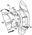
Referring to fig. 18, the gas sealing access cover 28 includes a main housing portion 122 that defines an internal cavity 124 that supports a two-piece annular jet assembly 126 for receiving pressurized gas from an inlet port 128 in communication with the gas inlet lumen 116 of the connector 114. The annular jet assembly 126 is adapted and configured to create a gas seal within the robotic cannula 28 to maintain a stable pressure within the surgical cavity of the patient. The structure and function of the jetting assembly 126 is described in commonly assigned U.S. patent No. 8,795,223, the disclosure of which is incorporated herein by reference in its entirety.
The main housing portion 122 of the access cover 28 includes a mounting flange 125 for cooperatively receiving the manifold 120 of the multi-lumen connector 114. A sound attenuating disc 128 made of foam material is positioned within the main housing portion 122 of the gas seal access cover 26, proximal to the annular jet assembly 126, for reducing the sound level generated by the pressurized gas flowing through the jet assembly 126. A cover 130 engages the proximal end of the outer housing portion 122 to secure the annular jetting assembly 126 and the sound attenuating disk 128 within the main housing portion 122. The cover 130 defines a primary access port 135 for gas sealing access to the cover 26 through which surgical instruments and the like are introduced into the robotic cannula 28.
Additionally, as best seen in fig. 19, the main housing portion 122 of the gas seal entry cap 26 includes an integrally formed body of circumferentially spaced vanes 132 for directing exhaust gas from the gas seal zone to the outlet lumen 118 of the connector 114 through an outlet port 134 in the main housing portion 122 of the gas seal entry cap 26. In the multi-mode gas delivery system 12 shown in FIG. 1, such exhaust gas is drawn from the zone by the recirculation flow generated by pump 16. In some cases, the exhaust gas may include smoke-laden gases generated in the surgical cavity.
The bodies of the integrally formed circumferentially spaced vanes 132 surround the inner periphery of the internal cavity 124 of the main housing portion 122 and they extend distally to an inwardly tapered integral tubular extension 136 that extends distally into the proximal bowl portion 110 of the robotic cannula 28. Similar guide vanes are described in commonly assigned U.S. patent No. 8,795,223, but they are not integrally formed with the housing.
An outer O-ring 138 surrounds a lower section of the main housing portion 122 such that it is positioned between the main housing portion 122, which is gas sealed into the lid 26, and the proximal bowl portion 110 of the robot sleeve 28 to form a gas tight seal therebetween. The main housing portion 122 of the gas-tight access cover 26 also includes a pair of diametrically opposed flexible clamps 140a, 140b adapted and configured to releasably latch to an upper annular flange 142 of the proximal bowl portion 110 of the robot sleeve 28, as shown, for example, in fig. 15 and 16.
Referring now to fig. 20-22, in another embodiment of the invention, the multi-lumen connector of the gas-tight entry port 26 is a triple lumen bullseye connector, generally indicated by reference numeral 214. A triple lumen connector of this type is disclosed in commonly assigned U.S. patent No. 9,526,886, the disclosure of which is incorporated herein by reference in its entirety. This feature is currently used in commercially available AirSeal access port products manufactured and sold by SurgiQuest, inc, a proprietary company of ConMed Corporation, and is therefore a readily available component. For this reason, it can be readily adapted for use with a gas-tight access cover 26, thereby reducing the manufacturing cost and time-to-market of such new access devices.
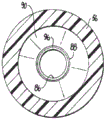
More specifically, as shown in fig. 20 and 21, a triple lumen bullseye connector 214 for accessing the cap 26 includes an outer lumen 216 for receiving gas from the pressurized gas line 34, a central lumen 218 for discharging exhaust gas to the gas return line 36, and an intermediate lumen 217 therebetween. In this case, the intermediate lumen 217 is not connected to any gas line of the tube set 20, and the inlet region 137 located within the boundaries of the mounting flange 125 is blocked or otherwise obscured, thus making the intermediate lumen 217 unimportant. Which is essentially a residual or unused feature of the connector 214. Thus, the triple lumen bulls-eye fitting 248 shown in fig. 22 is associated with only the double lumen portion 22 (i.e., lumens 34 and 36) of the tube set 20, even though the fitting 248 is adapted and configured to mate with the triple lumen connector 214.
Turning now to fig. 23-26, there is shown another embodiment of a bullseye connector fitting, generally designated by the reference numeral 150, for rotatably coupling with the connector 114 of the gas sealing access cover 26 of the present invention. The bullseye connector fitting 150 includes a proximal portion 152 for receiving the double lumen portion 22 of the tubing set 20 and a distal portion 154 for engaging the spaced apart lugs or posts 145 on the connector 114. The distal portion 154 of the connector fitting 150 includes a set of generally J-shaped slots 156 for receiving the lugs 145.
As best seen in fig. 25 and 26, each J-shaped slot 156 has a front leg section 158 and a rear leg section 160. An enlarged ball 162 is formed at the entrance to the rear leg section 158 of the slot 156, which must be overcome by the rotational force during coupling so that the lug 145 can be locked in place. Those skilled in the art will readily appreciate that the coupling features shown in fig. 23-26 may be employed with either a dual lumen connector fitting or a triple lumen connector fitting in accordance with the present invention.
Referring to fig. 27-30, there is shown another embodiment of a bullseye connector fitting, generally designated by the reference numeral 170, for rotatably coupling with the connector 114 of the gas sealing access cover 26 of the present invention. The connector fitting 170 includes a proximal portion 172 for receiving the double lumen portion 22 of the tubing set 20 and a distal portion 174 for engaging the spaced lugs or posts 145 on the connector 114.
The distal portion 174 of the connector fitting 170 includes a set of circumferentially spaced generally hockey stick-like slots 176 that define a helical coupling feature for receiving the lugs 145 and for frictionally retaining the lugs 145 in a locked position within the slots 176 as the fitting 170 is rotated clockwise relative to the connector 114, as best seen in fig. 29 and 30. Those skilled in the art will readily appreciate that the coupling features shown in fig. 27-30 may be employed with either a dual lumen connector fitting or a triple lumen connector fitting in accordance with the present invention.
Referring to fig. 31-36, an attachment mechanism for releasably attaching an embodiment of a gas seal access cover 26 to the proximal bowl portion 110 of the robotic cannula 28 is illustrated, rather than the diametrically opposed flexible clamps 140a, 140b previously described herein and illustrated in fig. 16 and 17. More specifically, fig. 31-36 illustrate an elliptical compressible clamping skirt 220 integral with and surrounding the lower section of the main housing portion 122 of the gas seal access cover 26.
Compressible clamping skirt 220 has two diametrically opposed compression tabs 222a, 222b and two diametrically opposed clamp projections 223a, 223b with windows 227a, 227b for moldability. The compression tabs 222a, 222b are adapted and configured to enable application of manual force to the skirt 220 in a radially inward direction, as shown in fig. 35. This causes the skirt 220 to expand radially outward along an axis generally transverse to the force vector such that the clamp projections 223a, 223b can be physically released from under the proximal flange 142 of the bowl portion 110 of the access lid 26. Diametrically opposed C-shaped cutouts 229a, 229b are formed in the clamping skirt 220 adjacent to the compression tabs 222a, 222b, respectively, to allow greater displacement of the clamp projections 223a, 223b and reduce the overall stiffness of the clamping skirt 220.
As best seen in fig. 33, the compressible ring 226 is positioned below the clamping skirt 220 such that it sits between the clamping skirt 220 and the proximal flange 142 of the bowl portion 110 to provide a seal and a resilient biasing force therebetween, thereby enhancing the safety of the clamping skirt 220. It is contemplated that the gasket 226 may be an overmolded elastomer, a flat O-ring, or a foam material. Those skilled in the art will readily appreciate that the attachment features shown in fig. 31-36 may be employed with a valve seal access cap 30 according to the present invention.
Referring now to fig. 37-40, an attachment mechanism defined by a spring-biased and hinged snap assembly 230 for releasably attaching an embodiment of a gas-tight access cover 26 to the proximal bowl portion 110 of the robotic cannula 28 is shown. The buckle assembly 230 includes a pair of C-shaped buckle portions 232a, 232b hingedly attached to one another about a pivot pin 234, as best seen in fig. 39. The snap assembly 230 may be supported on the lower annular flange 224 of the main housing portion 122 of the access cover 26 or it may be a separate component.
The two snap portions 232a, 232b are normally biased toward each other to the closed and locked position shown in fig. 37 by a torsion spring 236 associated with the pivot pin 234. The snap assembly 230 is adapted and configured for manual movement between an open position shown in fig. 38 that allows for easy manual separation of the gas-tight access cover 26 from the bowl portion 110 of the robot sleeve 28 and a closed position shown in fig. 37 in which the snap portions 232a, 232b close around the annular flange 224 on the main housing portion 122 of the access cover 26 and the proximal flange 142 of the bowl portion 110 of the robot sleeve 28 to securely retain them by a friction fit, as best seen in fig. 40. Those skilled in the art will readily appreciate that the snap-on attachment feature shown in fig. 37-40 may be employed with a valve seal access cap 30 according to the present invention.
Referring now to fig. 41-43, another attachment mechanism for releasably attaching an embodiment of a gas seal access lid 26 to the proximal bowl portion 110 of the robot sleeve 28 is shown, defined by a magnetic skirt assembly 240. The magnetic skirt assembly 240 includes a magnetic ring 242 that may be overmolded onto the underside of the housing flange 224 such that it may interact directly with the metallic proximal flange 142 of the bowl portion 110 of the sleeve 28, as best seen in fig. 42. Alternatively, the magnetic ring 242 may be ultrasonically welded between the two clip-free plastic skirts 244 and 246, and then the components may be secured together to the lower surface of the annular flange 224 of the housing 122, as shown in fig. 43. Those skilled in the art will readily appreciate that the magnetic attachment feature shown in fig. 41-43 may be employed with a valve seal access cap 30 according to the present invention.
Referring to fig. 44-46, there is shown an attachment mechanism for releasably attaching an embodiment of a gas sealing access cover 26 to the proximal bowl portion 110 of the robotic cannula 28, the attachment mechanism being defined by a compressible gripping skirt 250 similar in structure and function to that shown in fig. 36, but in the embodiment of the invention schematically illustrated, the compressible gripping skirt 250 is inverted and mounted for axial movement relative to the bowl portion 110 of the cannula 28, as best seen in fig. 45.
More specifically, the axially movable inverted clamp skirt 250 may be raised and lowered relative to the bowl portion 110 of the robot sleeve 28 to facilitate releasably attaching the gas-tight access cover 26 to the robot sleeve 28. Those skilled in the art will readily appreciate that the movable clamping skirt feature shown in fig. 44-46 may be employed with a valve seal access cap 30 according to the present invention.
Referring now to fig. 47, a three-lumen bullseye plug 260 is shown that is adapted and configured to mate with a three-lumen bullseye connector fitting 248 associated with the double lumen portion 22 of the tube set 20 shown in fig. 22. The bullseye plug 260 is used, for example, during an initial filling phase of a robot-assisted surgery when the double lumen portion 22 of the tubing set 20 is not employed, but instead the single lumen portion 24 of the tubing set 20 is employed. When the bullseye plug 260 is installed, it creates a negative pressure in the double lumen portion 22 of the tubing set 20, which indicates to the pressure sensor in the gas delivery system 12 that a standard fill mode is in progress. At this point, the pump 16 within the gas delivery system 12 will not operate.
Turning now to FIG. 48, the Da Vinci robot sleeve 28 employed with the gas sealing access cover 26 of the present invention is shown in detail, as previously illustrated, for example, in FIG. 1. As can be readily seen, the elongate body portion 112 of the robotic cannula 28 has an internal bore 115 with an inner diameter D of about 8.89mm and is sized to receive the shaft of a robotic instrument with an outer diameter of about 8.55mm, which shaft is not shown. This allows a gap of 0.39mm between them for airflow. However, the gas seal access cover 26 requires a larger gap to function effectively. To enhance the function of the gas sealing access cover 26 of the present invention, a cannula having a larger inner diameter is required so that pressurized gas can more easily flow between the inner periphery of the interior bore 115 and the outer periphery of the robotic instrument extending therethrough.
In this regard, fig. 49 illustrates a robotic cannula body 270 having a set of circumferentially spaced linear beads 272 formed or otherwise disposed on an inner surface thereof to provide enhanced gas flow for gas sealing into the cover 26. Similarly, fig. 50 shows a robotic cannula body 280 having a set of circumferentially spaced apart linear channels 284 formed in the inner surface thereof to provide enhanced gas flow for gas sealing into the cover 26. Finally, fig. 51 shows a robotic cannula body 290 having a continuous helical bead 292 formed or otherwise disposed on an inner surface thereof to provide enhanced airflow between an inner wall of the cannula body 290 and a robotic instrument 300 extending therethrough, as best seen in fig. 52. Those skilled in the art will readily appreciate that these features of the sleeve body may also provide enhanced airflow when used in conjunction with a valve seal access cap 30.
While the gas circulation system of the present disclosure has been shown and described with reference to the preferred embodiments, those skilled in the art will readily appreciate that changes and/or modifications may be made thereto without departing from the scope of the present disclosure.