Honeycomb structure air coupling ultrasonic signal feature extraction method
Technical Field
The invention belongs to the technical field of ultrasonic detection, and particularly relates to a honeycomb structure space coupling ultrasonic signal feature extraction method.
Background
Honeycomb sandwich structures are a type of material consisting of two strong panels (called skins) and a lightweight core, which are joined together by an adhesive film. The structure has excellent comprehensive properties such as low weight, high hardness, relatively high flame retardance and the like, and is widely applied to weight sensitive fields such as aerospace, rail transit and the like. However, in the manufacturing and using processes, the honeycomb sandwich structure inevitably has the defect of debonding inside the material, and the defect reduces the hardness and fatigue resistance of the material, thereby affecting the safety of the whole part structure. Therefore, the method has great significance for debonding nondestructive testing of the honeycomb sandwich structure.
Many non-destructive inspection techniques have been developed to identify debonding of cellular structures at this stage, including electromechanical impedance methods, thermography methods, radiographic detection methods, and ultrasonic detection methods. The electromechanical impedance method judges whether defects exist in the detected part or not according to different electric responses caused by different damage degrees of the structure, however, the sensor is bonded with the detected material, certain deviation is inevitably brought to the impedance characteristic of the detected material, and online real-time large-batch nondestructive detection is difficult to realize. The thermal imaging method detects the detected material and the defect according to the temperature change condition after infrared radiation is used, but the detected material has too thick skin or the skin material is not sensitive to temperature, so the detection is difficult. The ray detection method utilizes attenuation of different degrees when X-rays and Y-rays transmit different materials, and judges the bonding quality of the structure through negative images with different photosensitive blackness. But the radiation detection equipment is large and can cause injury to detection personnel after long-term use. The conventional ultrasonic detection method detects according to the difference of acoustic impedances of materials and defects, is a mature detection method, but the conventional ultrasonic detection method needs a coupling agent to pollute the surface of the detected material and has low efficiency. Compared with the conventional ultrasonic detection, the air-coupled ultrasonic technology does not need a coupling agent, so that the pollution and damage of the coupling agent to the surface of the material can be avoided, and the rapid detection is realized.
In the air coupling ultrasonic detection process, because the acoustic impedance of the honeycomb structure composite material is far smaller than that of air, the energy loss of ultrasonic waves entering the material from the air is large, and the amplitude of a characteristic signal is small. In addition, in the ultrasonic detection, ultrasonic waves are scattered due to the rough surface of the honeycomb composite material, and factors such as hardware noise in a probe or a transmission line can cause the ultrasonic signals to generate noise, so that the extraction of useful signals is influenced. Therefore, it is necessary to perform noise reduction processing on the signal to improve the signal-to-noise ratio.
In recent years, wavelet de-noising and Empirical Mode Decomposition (EMD) have become more widely used for de-noising ultrasound signals. Wavelet analysis-based lithium battery space coupling ultrasonic signal denoising research (Yue nations, ship science and technology) and wavelet analysis-based lithium battery space coupling ultrasonic signal denoising research (Zhanman, test technology report) respectively apply wavelet decomposition technology to ship titanium alloy ultrasonic detection signal denoising processing and air coupling ultrasonic detection lithium battery ultrasonic signal denoising processing. An ultrasonic signal denoising method based on empirical mode decomposition and wavelet analysis (Liu's backup) combines the empirical mode decomposition and wavelet analysis, and reconstructs a signal after wavelet denoising is carried out on a noise-containing component, so that the denoising effect is improved compared with the simple EMD denoising. An ultrasonic detection signal adaptive noise reduction method based on improved CEEMD (Sun Ling Fang writings) discloses a noise reduction method using autocorrelation function characteristics of CEEMD, aiming at the problem of judging the dividing point of noise and characteristic signal components, and realizing the decomposition, adaptive noise reduction and reconstruction of signals. However, wavelet analysis needs to select a proper threshold and a proper wavelet basis function, and the EMD lacks a strict mathematical derivation and has the defects of end point effect, modal aliasing and the like.
Vmd (spatial Mode decomposition) has a strict mathematical basis compared to EMD and improves the end-point effect and modal aliasing problems as a new method of signal decomposition. However, due to the complexity of the ultrasonic signal noise, it is difficult to achieve good noise reduction using VMDs. Independent Component analysis ICA (independent Component analysis) can separate independent signals according to a plurality of observation signals, but the ICA algorithm only carries out time domain analysis on the algorithm, and certain limitation is brought to the de-noising of ultrasonic signals. Aiming at the traditional ultrasonic signal denoising method, a denoising method combining a VMD method and an ICA method is provided.
Disclosure of Invention
The invention aims to provide a honeycomb structure space-coupled ultrasonic signal feature extraction method based on VMD-ICA, the feature signal and the noise reduction effect extracted by the method are superior to wavelet noise reduction and EMD noise reduction algorithms, and the feature signal of space-coupled ultrasonic can be accurately extracted.
In order to achieve the above purpose, the solution of the invention is: a method for extracting characteristics of air-coupled ultrasonic signals of a honeycomb structure comprises the following steps
The method comprises the following steps: acquiring a noise-containing original signal f by using an air coupling ultrasonic probe;
step two: decomposing the original signal into a plurality of modal components by the VMD;
step three: then calculating the correlation coefficient of each modal component and the original signal, and comparing the modal component with the maximum correlation coefficient;
step four: and constructing a matrix by the maximum modal component and the original signal, and finally separating the characteristic signal and the noise in the matrix through the ICA.
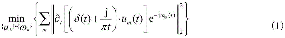
Further, in step two, the VMD decomposes the original signal f into K modal components uk,
For an original signal f, the VMD decomposition steps are as follows:
(1) using Hilbert transform to obtain analytic signals of modal components, each analytic signal having a different center frequency ωk;
(2) For each center frequency omegakAdopting index correction;
(3) obtaining each section of bandwidth of the demodulation signal through Gaussian smoothing, solving the bandwidth of each modal component by the Gaussian smoothing method of the demodulation signal, and further constructing a variation model with constraint conditions
In the formula uk={u1,…,ukIs the set of modal components, ωk={ω1,…,ωkIs the set of center frequencies;
introducing a penalty factor alpha, constructing an augmented Lagrange function, and solving each modal component;
converting the Lagrange function from time domain to frequency domain and solving extreme value to obtain modal component ukAnd center frequency omegakThe frequency domain expression of (a):
finally, the alternative direction multiplier algorithm is adopted to alternately search ukAnd ωk。
Further, in step three, each modal component u is decomposedkCalculating the correlation coefficient with the original signal f by the formula (6)
Further, in step four, the modal component u having the largest correlation coefficient with the original signal is selectedxAnd original signal f to construct observation matrix X ═ ux,f]The observation matrix X is composed of two independent signals S ═ S1,s2]The linear combination is as follows:
X=AS (6)
wherein A is a 2 x 2-order mixing matrix, and S is an independent component matrix;
solving a unmixing matrix W according to the measurement observation matrix X, and finally solving an optimal independent component matrix
I.e. the signature and noise.
After the scheme is adopted, the invention has the beneficial effects that:
the VMD and ICA algorithms are combined and applied to the extraction of the characteristics of the air-coupled ultrasonic signals of the honeycomb sandwich structure, the effect is obvious, the bottleneck of the traditional ultrasonic detection is broken through, and the method has certain research significance for the debonding detection of metal-nonmetal and the nondestructive detection of materials which are difficult to use coupling agents, such as bubbles in lithium batteries and the like.
Drawings
FIG. 1 is a schematic view of the ICA of the present invention;
FIG. 2 is a schematic diagram of VMD-ICA denoising process according to the present invention;
FIG. 3 is a waveform diagram of an uncoded simulation signal according to the present invention;
FIG. 4 is a schematic diagram of a waveform of a noise-added simulation signal according to the present invention;
FIG. 5 shows a VMD decomposition u of the simulation signal according to the present invention1A schematic diagram of the waveform of (a);
FIG. 6 shows a VMD decomposition u of the simulation signal of the present invention2A schematic diagram of the waveform of (a);
FIG. 7 shows a VMD decomposition u of the simulation signal according to the present invention3A schematic diagram of the waveform of (a);
FIG. 8 shows a VMD decomposition u of the simulation signal according to the present invention4A schematic diagram of the waveform of (a);
FIG. 9 is a schematic diagram of a denoising result of a simulation signal VMD-ICA algorithm of the present invention;
FIG. 10 is a diagram illustrating a wavelet denoising result of a simulation signal according to the present invention;
FIG. 11 is a diagram illustrating an EMD denoising result of the simulation signal according to the present invention;
FIG. 12 is a schematic diagram of an actually measured honeycomb structure air-coupled ultrasonic signal according to the present invention;
FIG. 13 shows a VDM decomposition u of a measured signal according to the present invention1A schematic diagram of the waveform of (a);
FIG. 14 shows a VMD decomposition u of a measured signal according to the present invention2A schematic diagram of the waveform of (a);
FIG. 15 shows a VMD decomposition u of a measured signal according to the present invention3A schematic diagram of the waveform of (a);
FIG. 16 shows a VMD decomposition u of the measured signal according to the present invention4A schematic diagram of the waveform of (a);
FIG. 17 shows a VMD decomposition u of the measured signal according to the present invention5A schematic diagram of the waveform of (a);
FIG. 18 is a schematic diagram of a denoising result of a measured signal VMD-ICA algorithm according to the present invention;
FIG. 19 is a diagram illustrating an EMD denoising result of an actually measured signal according to the present invention;
FIG. 20 is a diagram illustrating a wavelet de-noising result of an actual measurement signal according to the present invention.
Detailed Description
The invention is described in detail below with reference to the accompanying drawings and specific embodiments.
The invention provides a method for extracting characteristics of a honeycomb structure air-coupled ultrasonic signal, which comprises the following steps of
The method comprises the following steps: acquiring a noise-containing original signal f by using an air coupling ultrasonic probe;
step two: firstly, decomposing the original signal into a plurality of modal components (IMF) by VMD, determining the decomposition number by a central frequency observation method, wherein the VMD is to decompose the original signal f into K modal components ukAnd obtaining a model optimal solution in an iterative mode to determine the center frequency and the bandwidth of each modal component, thereby realizing the effective separation of each component of the self-adaptive signal.
For an original signal f, the VMD decomposition steps are as follows:
(1) using Hilbert transform to obtain analytic signals of modal components, each analytic signal having a different center frequency ωk;
(2) For each center frequency omegakAdopting index correction;
(3) obtaining each section of bandwidth of the demodulation signal through Gaussian smoothing, solving the bandwidth of each modal component by the Gaussian smoothing method of the demodulation signal, and further constructing a variation model with constraint conditions
In the formula uk={u1,…,ukIs the set of modal components, ωk={ω1,…,ωkIs the set of center frequencies;
introducing a penalty factor alpha, constructing an augmented Lagrange function, and solving each modal component;
converting the Lagrange function from time domain to frequency domain and solving extreme value to obtain modal component ukAnd center frequency omegakThe frequency domain expression of (a):
finally, the alternative direction multiplier algorithm is adopted to alternately search ukAnd ωk。
Step three: then, the correlation coefficient of each modal component and the original signal is calculated by the formula (6)
Comparing the modal component u with the maximum correlation coefficientx;
Step four: constructing a matrix by the maximum modal component and the original signal, and finally separating characteristic signals and noise in the matrix through ICA;
ICA Algorithm As shown in FIG. 1, the modal component u having the largest correlation coefficient with the original signalxAnd original signal f to construct observation matrix X ═ ux,f]The observation matrix X is composed of two independent signals S ═ S1,s2]The linear combination is as follows:
X=AS (6)
wherein A is a 2 x 2-order mixing matrix, and S is an independent component matrix;
solving a unmixing matrix W according to the measurement observation matrix X, and finally solving an optimal independent component matrix
I.e. the signature and noise.
The invention can also use a FastICA algorithm for calculation, wherein the FastICA algorithm is a Fast iterative optimization algorithm of ICA proposed by Finnish scholars Hyvannn in 1999, and the optimization strategy is processed and iterated in a large sample data parallel calculation mode. Therefore, the method has higher efficiency.
The VMD decomposition can decompose the original signal into different central frequency bands, obtain the modal component with the maximum correlation coefficient by calculating the correlation coefficient of each modal component and the original signal, and separate the noise and the useful signal by using FastICA for the modal component and the original signal construction matrix. Therefore, the VMD and ICA combined denoising is referred to as VMD-ICA denoising in the invention, and a flow chart is shown in FIG. 2.
In order to verify the effectiveness of the VMD-ICA algorithm, Gaussian signals and sinusoidal signals are utilized to simulate ultrasonic signals, white noise with high intensity is added into the simulated signals to obtain noise signals, and when the signal-to-noise ratio is-10 dB, the noise signals accord with the signal characteristics of the air coupling ultrasonic detection honeycomb structure. The simulated signal is shown in fig. 3, and the simulated signal after noise addition is shown in fig. 4.
Determining the VMD decomposition modal number K according to the central frequency observation method, wherein the central frequencies of various modal components of the simulation test signals under different K values are listed in Table 1,
TABLE 1
It can be seen that when K is 5, u3And u4Are close, it is considered that the over-resolution phenomenon occurs. Therefore, the decomposition results are shown in fig. 5 to 8, assuming that the K value is 4. The maximum component of the correlation coefficient was obtained by calculating the correlation coefficient between each component and the simulated noise signal, and the calculation results are shown in table 2.
TABLE 2
U having the largest number of correlations1And constructing a matrix by the components and the simulated noisy signals, and separating the noise and the useful signals by a FastICA algorithm. Comparing the algorithm with an EMD denoising algorithm and a wavelet denoising algorithm, the denoised signal of the invention is shown in FIG. 9, the denoised signal of the wavelet denoising algorithm is shown in FIG. 10, and the denoised signal of the EMD denoising algorithm is shown in FIG. 11, wherein the wavelet basis function in the wavelet denoising selects sym11, and the number of layers is 9. The evaluation indexes are selected from signal-to-noise ratio (SNR), Root Mean Square Error (RMSE) and similarity coefficient (NCC), the noise reduction effect is listed in the following table 3,
TABLE 3
The formula for SNR, RMSE, NCC is as follows:
wherein, X (n) is a noise-containing original signal; s (n) is a signal after noise reduction; and N is the signal length.
When the signal-to-noise ratio is-10 dB, the VMD-ICA algorithm and the wavelet denoising algorithm can realize signal denoising, the EMD denoising algorithm submerges characteristic signals in noise, and the denoising effect is not ideal. Compared with a wavelet denoising algorithm, the VMD-ICA algorithm provided by the invention has smoother waveform, more obvious characteristic signals and better denoising effect. For SNR, RMSE and NCC after three methods process simulation signals, the VMD-ICA method provided by the invention has optimal noise reduction index, and the effectiveness of the method is verified.
And (3) vertically placing a transmitting probe on one side of the honeycomb composite material by using an air coupling ultrasonic transmission method in the honeycomb sandwich structure, placing a receiving probe on the other side for receiving, wherein the probe is a circular focusing air coupling ultrasonic probe with the transmitting frequency of 400kHZ, the focusing distance is 4cm, and the thickness of a honeycomb composite material test piece is 5 cm. The sampling frequency of the signal is 10MHz, and the gain is 40 dB. The acquired measured signal is shown in fig. 12, and the signal contains serious noise, cannot distinguish a characteristic signal, and has an analysis ultrasonic effect on a subsequent signal. Therefore, the invention is utilized to carry out noise reduction processing on the noisy signal.
Determining a VMD decomposition mode number K according to a center frequency observation method, listing the center frequency of each mode component under different K values in Table 4, and when K is 6, u1And u2Are close, an over-resolution phenomenon occurs. Therefore, K is taken to be 5. The decomposition results are shown in fig. 13 to 17, and each modal component u is divided into1To u5The correlation coefficient was calculated with the measured signal and the calculation results are listed in table 5.
TABLE 4
TABLE 5
From Table 5, it can be seen that u1The correlation coefficient with the original signal is maximum, so u is considered to be1Contains the most characteristic signals. Will u1The signal is combined with the original signal to construct a matrix, and then ICA is used to separate noise and characteristic signals. The processed signal (fig. 18) is compared to the EMD denoising algorithm (fig. 19) and the wavelet denoising algorithm (fig. 20).
It can be seen that the EMD denoising algorithm and the wavelet denoising algorithm are both difficult to extract weak feature signals from strong noise, and the VMD-ICA algorithm used herein effectively extracts feature signals from original signals. The method can realize signal noise reduction and characteristic signal extraction of the air coupling ultrasonic detection honeycomb composite material.
The method comprises the steps of firstly, establishing a reasonable two-dimensional intact finite element model and a defect model by analyzing the three-dimensional structural characteristics of the honeycomb sandwich structure composite material, realizing the visualization of sound wave propagation in the material, analyzing the signal change trend and verifying through experiments. And finally, constructing an air coupling ultrasonic C scanning system, carrying out imaging treatment on the debonding defects inside the honeycomb sandwich structure, and analyzing the result.
The invention has the advantages that:
(1) the air coupling ultrasonic transmission detection method is used for researching debonding nondestructive testing of the honeycomb sandwich structure, the problems of pollution, low efficiency and the like caused by the need of a coupling agent in common ultrasonic testing can be solved, and online nondestructive testing is realized.
(2) Establishing an air coupling ultrasonic transmission two-dimensional finite element model, simulating actual debonding defects by arranging air layers with different sizes, and obtaining from simulation results that compared with parts which are not debonded, the debonding defects can reduce the amplitude of ultrasonic transmission signals and the larger the debonding defects are, the lower the amplitude is.
(3) And designing an integral experiment system to complete the debonding air coupling ultrasonic transmission method detection system of the honeycomb sandwich structure, detecting 8 artificial debonding defects with different sizes, wherein the experiment result is identical with the simulation result, and verifying the effectiveness of the detection method.
(4) Air coupling ultrasonic C scanning imaging is carried out on the honeycomb sandwich structure, the phi 5mm debonding defect can be detected at minimum, and imaging of the phi 9mm debonding defect can be realized. In addition, the method is not only suitable for debonding detection of the honeycomb sandwich structure, but also has certain research significance for debonding detection of metal-nonmetal and nondestructive detection of materials which are difficult to use coupling agents, such as air bubbles in a lithium battery.
The above description is only a preferred embodiment of the present invention, and is not intended to limit the design of the present invention, and all equivalent changes made in the design key point of the present invention fall within the protection scope of the present invention.