CN113495563A - Traffic vehicle lane change decision planning method for automatic driving virtual test - Google Patents
Traffic vehicle lane change decision planning method for automatic driving virtual test Download PDFInfo
- Publication number
- CN113495563A CN113495563A CN202110646151.4A CN202110646151A CN113495563A CN 113495563 A CN113495563 A CN 113495563A CN 202110646151 A CN202110646151 A CN 202110646151A CN 113495563 A CN113495563 A CN 113495563A
- Authority
- CN
- China
- Prior art keywords
- lane
- change
- lane change
- changing
- traffic vehicle
- Prior art date
- Legal status (The legal status is an assumption and is not a legal conclusion. Google has not performed a legal analysis and makes no representation as to the accuracy of the status listed.)
- Granted
Links
- 230000008859 change Effects 0.000 title claims abstract description 287
- 238000000034 method Methods 0.000 title claims abstract description 62
- 230000008569 process Effects 0.000 claims abstract description 29
- 208000019901 Anxiety disease Diseases 0.000 claims description 35
- 230000036506 anxiety Effects 0.000 claims description 35
- 230000008450 motivation Effects 0.000 claims description 26
- 241001122315 Polites Species 0.000 claims description 19
- 238000005070 sampling Methods 0.000 claims description 18
- 238000004364 calculation method Methods 0.000 claims description 17
- 238000011156 evaluation Methods 0.000 claims description 14
- 230000001133 acceleration Effects 0.000 claims description 12
- 238000002360 preparation method Methods 0.000 claims description 9
- 238000012216 screening Methods 0.000 claims description 9
- 230000003993 interaction Effects 0.000 abstract description 4
- 238000004088 simulation Methods 0.000 description 8
- 238000012360 testing method Methods 0.000 description 5
- 238000010586 diagram Methods 0.000 description 4
- 238000012986 modification Methods 0.000 description 2
- 230000004048 modification Effects 0.000 description 2
- 238000011160 research Methods 0.000 description 2
- 230000004075 alteration Effects 0.000 description 1
- 230000009286 beneficial effect Effects 0.000 description 1
- 230000001413 cellular effect Effects 0.000 description 1
- 230000007547 defect Effects 0.000 description 1
- 238000013461 design Methods 0.000 description 1
- 238000011161 development Methods 0.000 description 1
- 239000006185 dispersion Substances 0.000 description 1
- 230000004973 motor coordination Effects 0.000 description 1
- 230000001105 regulatory effect Effects 0.000 description 1
- 238000006467 substitution reaction Methods 0.000 description 1
- 238000012795 verification Methods 0.000 description 1
Images


Classifications
-
- G—PHYSICS
- G05—CONTROLLING; REGULATING
- G05D—SYSTEMS FOR CONTROLLING OR REGULATING NON-ELECTRIC VARIABLES
- G05D1/00—Control of position, course, altitude or attitude of land, water, air or space vehicles, e.g. using automatic pilots
- G05D1/02—Control of position or course in two dimensions
- G05D1/021—Control of position or course in two dimensions specially adapted to land vehicles
- G05D1/0212—Control of position or course in two dimensions specially adapted to land vehicles with means for defining a desired trajectory
- G05D1/0223—Control of position or course in two dimensions specially adapted to land vehicles with means for defining a desired trajectory involving speed control of the vehicle
Landscapes
- Engineering & Computer Science (AREA)
- Aviation & Aerospace Engineering (AREA)
- Radar, Positioning & Navigation (AREA)
- Remote Sensing (AREA)
- Physics & Mathematics (AREA)
- General Physics & Mathematics (AREA)
- Automation & Control Theory (AREA)
- Traffic Control Systems (AREA)
- Control Of Driving Devices And Active Controlling Of Vehicle (AREA)
Abstract
The invention discloses a traffic vehicle lane change decision planning method for an automatic driving virtual test, which comprises the following specific processes: determining a forced lane change target lane; judging a free lane change engine; determining a free lane change potential target lane; pre-judging the coordination of the lane changing motor; judging whether the current lane is in a forced lane changing target lane or not; judging the urgency of forced lane change; judging the track changing time; and planning a lane changing track. The traffic vehicle lane change decision planning method can enable a traffic vehicle to plan a continuous lane change track according to the current traffic environment and the preset driving preference so as to improve the randomness and the fidelity of the traffic vehicle in the automatic driving virtual test and enable the simulated vehicles to form dynamic and effective interaction.
Description
Technical Field
The invention belongs to the technical field of automatic driving vehicle lane change control, and particularly relates to a traffic vehicle lane change decision planning method for an automatic driving virtual test.
Background
It is currently a common consensus in the automotive industry that virtual simulation is an important means of automated driving testing. As a virtual test traffic vehicle for replacing a real driver, the virtual test traffic vehicle has the task of embodying various driving styles and can effectively interact with other traffic participants, particularly with a vehicle to be tested. However, the movement of the traffic vehicle used in the automatic driving virtual test is not real enough at present, and is greatly different from the behavior of the traffic vehicle in reality, so that the method is difficult to be used for virtual development and verification of the automatic driving vehicle.
In the prior art, the traffic vehicle models for the automatic driving simulation test are roughly divided into two types, one is a preset track following model, and the other is a microscopic traffic flow model. Wherein:
the traffic vehicles running in a preset trajectory following manner are mainly found in automatic driving development testing tools, such as VTDs, caras, and the like. The preset track following mode is as follows: the traffic vehicle moves according to a preset track before simulation or a track randomly generated in the simulation process, and the interaction with other vehicles is limited to keep a certain safe distance to prevent collision. In the preset track following mode, the motion track needs manual design, but in the prior art, the provided test scenes are not rich enough, and the interaction of a complete closed loop between a traffic vehicle and a tested main body is difficult to form.
Traffic vehicles operated in a microscopic traffic flow mode are mainly used as microscopic traffic simulation tools for researches such as macroscopic traffic control, traffic congestion analysis and dispersion, for example, SUMO, and the microscopic traffic flow mode is recently and gradually applied to automatic driving simulation to provide a random dynamic environment for automatic driving tests. However, although the microscopic traffic flow model establishes a relatively complicated following model and lane changing model compared to the preset trajectory following model, it is still difficult to reproduce the lane changing process occurring in reality, which is mainly reflected in:
1. current microscopic traffic flow models divide lane-changing incentives into strategic lane-changing, tactical lane-changing, and collaborative lane-changing. Most of the motivations are considered from objective conditions, namely, lane changing can not be realized, and the judgment that the driver subjectively needs not to change lanes is not obviously reflected in the model.
2. The motion of the traffic vehicle is based on one-dimensional behavior simulation of a lane, and a full lateral motion model is not established or built, so that the motion track of a real vehicle cannot be simulated. In the model commonly used in SUMO, the lane change process is performed instantaneously. The relatively fine blank model is a lateral cellular automaton in nature, though lateral movement seems to exist, longitudinal and lateral movement is completely separated, and the movement capability of the whole actual vehicle cannot be considered.
Disclosure of Invention
Aiming at the defects in the prior art, the invention discloses a traffic vehicle lane change decision planning method for an automatic driving virtual test, which can enable a traffic vehicle to plan a continuous lane change track according to the current traffic environment and preset driving preference so as to improve the randomness and the fidelity of the traffic vehicle in the automatic driving virtual test and enable simulated vehicles to form dynamic and effective interaction.
The technical scheme of the invention is as follows by combining the attached drawings of the specification:
the traffic vehicle lane change decision planning method for the automatic driving virtual test comprises the following specific processes:
step S1: determining a forced lane change target lane;
step S2: judging a free lane change engine, if the lane change is needed, entering the step S3, and if the lane change is not needed, entering the step S5;
step S3: determining a free lane change potential target lane, if the free lane change potential target lane does not exist, returning to the step S2, and if the free lane change potential target lane exists, entering the step S4;
step S4: pre-judging the coordination of the lane changing motor, if the lane changing motor is coordinated, the step is S7, and if the lane changing motor is not coordinated, the step is S5;
step S5: judging whether the lane is currently in the forced lane changing target lane, if not, entering the step S6, and if so, returning to the step S2;
step S6: judging the urgent lane change, if the urgent lane change is required, the step proceeds to step S7, and if the urgent lane change is not required, the step returns to step S2;
step S7: judging the track changing time, if the track changing can be executed currently, entering the step S8, if the track changing can not be executed currently, waiting the track changing time until the track changing can be executed;
step S8: and planning a lane changing track.
In step S1, the formula for determining the forced lane change target lane is specifically as follows:


in the formula for determining the forced lane change target lane:
MRPjis a lane ljWhether to comply with the judgment result of the macroscopic path planning, if MRP j1, lane ljThe next road section can be driven; if MRP j0, lane ljThe next road segment cannot be driven;
a road section contains a plurality of target lanes conforming to the path plan LmIs the current traffic vehicle VehoAll forced lane change target lanes l in the road sectionmA collection of (a).
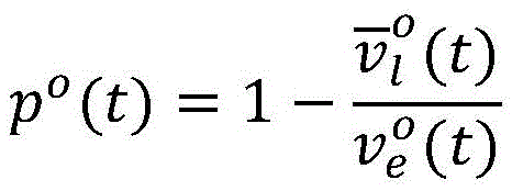
In step S2, the formula for determining the free lane change motivation is specifically as follows:

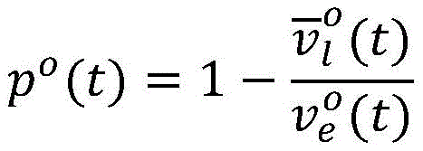

in the formula for judging the free lane change motivation, the formula comprises:


po(t) is the anxiety index;
DLCI is the judgment result of the free lane changing motivation;
when p iso(t) exceeding a preset anxiety index threshold pthWhen the DLCI is 1, judging that the channel needs to be freely changed;
when p iso(t) is less than a preset anxiety index threshold value pthAnd when the DLCI is 0, judging that the channel is not required to be freely changed.
In the step S3, after the lane change motivation is generated, it is checked whether the lane l exists in the current road sectiondTo ensure the traffic vehicle VehoIs reduced and is based on the traffic VehoScreening a potential target lane for the pre-estimated anxiety index of the lane k;
the calculation formula of the estimated anxiety index of the traffic vehicle to the lane is as follows:

in the formula for determining the estimated anxiety index of the traffic vehicle to the lane, the formula comprises the following steps:


the formula for screening the potential target lane is as follows:


in the formula for screening the potential target lanes:
DLCLkfor traffic vehicle VehoJudging whether the lane k conforms to a judgment result of freely changing a potential target lane;
when traffic vehicle VehoPredicted anxiety index for lane k Greater than the anxiety index threshold pth,DLCLkThe value is 0, the lane does not accord with the judgment condition of the free lane changing potential target lane, and the situation that the free lane changing potential target lane does not exist is judged;
when traffic vehicle VehoPredicted anxiety index for lane k Less than the anxiety index threshold pth,DLCLkThe value is 1, the lane accords with the judgment condition of the free lane change potential target lane, and the judgment is storedAnd changing the potential target lane freely.
In the step S4:
firstly, calculating the current lane l of the traffic vehicleoPotential target lane changing to free lane Urgency index urg to perform lane changekThe concrete formula is as follows:

the above urgency index urgkIn the calculation formula (2):
s0is a traffic vehicle VehoThe remaining length of the section;


the change from the current lane to the free lane change potential target lane Estimated longitudinal travel distance
 And freely changing lane of the potential target lane
 Changing to the nearest forced lane-changing target lane
 Estimated longitudinal travel distance
 The calculation formula of (a) is specifically as follows:


as described above And
And in the calculation formula (2):


estimated wait time The method is determined by taking the density of a target lane as an abscissa, pre-estimating waiting time as an ordinate and combining an intention representation time window of a lane changing driving style of a driver, wherein the intention representation time window is the time from the first attention of the driver to the rotation of a steering wheel;
then, judging whether the free lane change can be executed or not according to the urgent index of the traffic vehicle for executing the lane change from the current lane to the potential target lane of the free lane change, wherein the specific judgment formula is as follows:


in the above formula for judging whether the free lane change can be executed:
urgkfor traffic vehicles from the current lane loPotential target lane changing to free lane An urgency index to perform a lane change;
urgminfor traffic vehicles from the current lane loPotential target lane changing to free lane A minimum urgency index among urgency indexes for performing lane change;
DLCF is a judgment result of the feasibility of free lane change;
if the minimum urgency index urgminLess than a predetermined urgency threshold urgthIf DLCF is 1, the forced lane change and the free lane change have harmony, and the lane change motivation coordination is judged;
if the minimum urgency index urgminGreater than a predetermined urgency threshold urgth,DLCF is 0, the forced lane changing and the free lane changing do not have harmony, and the lane changing motivation is judged to be uncoordinated.
In the step S5:
when it is determined in step S3 that the free lane change is not required or it is determined in step S4 that the current lane condition does not permit the free lane change, the vehicle Veh for transportationoThe current lane needs to be determined, and the determination formula of the current lane is as follows:

in the above formula for determining the previous lane:
MLJ is the judgment result of the current lane;
if the current lane loIs to forcibly change the target lane lm,MLJ=1;
If the current lane loNot to forcibly change the target lane lm,MLJ=0。
In the step S6:
when the current lane of the traffic vehicle does not belong to the forced lane-changing target lane, calculating the lane l of the slave traffic vehicleoForced lane change target lane to nearest Lane change urgency index urgJThe calculation formula is specifically as follows:


the above-mentioned calculated lane change urgency index urgJIn the formula (2):


s0is a traffic vehicle VehoThe remaining length of the section;


in step S6, the lane change urgency index urg is calculatedJJudging the urgency of forced lane change;
the formula for judging the urgent forced lane change is specifically as follows:

in the formula for determining the urgency of forced lane change:
the MLCF is a judgment result of forced lane change urgency;
if the lane change is forced to be urgent, the index urgJGreater than a predetermined urgency threshold urgthWhen the MLCF is 1, judging that the lane needs to be changed urgently and forcibly;
if the lane change is forced to be urgent, the index urgJLess than the urgency threshold urgthAnd the MLCF is 0, and the judgment is that urgent forced lane change is not needed.
In step S7, the process of determining the track change timing includes:
step S71: determining the traffic vehicle VehoUrgency index urg ofoThe formula of (1) is as follows:

determining the traffic vehicle VehoTarget lane ltThe formula of (1) is as follows:

in step S72: the formula for determining the opportunity assessment index is:


in the formula for calculating the timing evaluation index LCIC:
LCIC is the timing assessment index;

aois the current traffic vehicle VehoLongitudinal acceleration of (a);
traffic vehicle VehnFor traffic vehicle VehoA rear vehicle to be converged into the lane;

anis the current traffic vehicle VehnIn the longitudinal direction ofSpeed;
δois a traffic vehicle VehoThe polite coefficient of (c);

urg is the urgency index of the current lane change behavior;
traffic vehicle VehoThe polite coefficient of (a) is related to the driving style initially set by the driving system and the lane change urgency; wherein:
the initial polite coefficient of a cautious driver, the initial polite coefficient of a common driver and the initial polite coefficient of an impulsive driver are reduced for one time;
lane change urgency index urgoThe lower the traffic vehicle VehoThe more the driver shows the behavior of giving the vehicle, the more the driver considers the rear traffic vehicle Veh of the target lanenA speed change of (d);
lane change urgency index urgoHigher, higher traffic vehicle VehoThe more the driver shows the behavior of lane change, the more the rear traffic Veh cannot take into account the target lanenIs changed.
Step S73: the channel change timing determination formula is specifically as follows:

in the above formula for determining track change timing:
LCMP is the judgment result of the channel change opportunity;
LCIC is opportunity evaluation index;
when the timing evaluation index LCIC is larger than the preset timing threshold LCICthWhen LCMP is 1, the traffic vehicle Veh is judgedoLane change can be currently performed;
when the timing evaluation index LCIC is smaller than the preset timing threshold LCICthWhen LCMP is 0, the vehicle Veh is judged to be the traffic vehicle VehoThe lane change is currently not possible.
In step S8, the specific process of planning the lane change trajectory is as follows:
step S81, dividing the track changing track into three stages: p0P1Preparation phase for lane change, P1P2Performing phase and P for lane change2P3For the track-changing end stage, and planning target track points P according to the stage0、P1、P2And P3;
Step S82: the determined target point P0、P1、P2And P3Smoothly connected to form a trajectory, wherein:
P1P2and P0P1The included angle between is alpha, P1P2And P2P3At an angle beta and in P1P2Is increased by a point Pm;
Note z0=0,P0P1A distance z between1=|P0P1|,P1PmA distance z between2=|P1Pm|,PmP2A distance z between3=|PmP2|,P2P3A distance z between4=|P2P3|;
Remember phi0=0,P1At a relative course angle of PmHas a relative course angle of phi2=α,P2At a relative course angle of
 P3Has a relative course angle of phi4=α-β;
P0Point time t0=0,P1Point time t1=1,PmPoint time t2=2,P2Point time t3=3,P3Point time t4=4;
Provision of P0Speed of dot z'0For the current trafficVehicle VehoActual vehicle speed z'0=vo,P0Angular velocity of dot phi'0=0,P3Speed of dot z'4Is a new lane lo′Front vehicle Vehf′Estimated vehicle speed z'4=vf′,P3Angular velocity of dot phi'4=0;
Interpolating (t, z) by cubic spline curve, and fixing the boundary as (t)0,z′0) And (t)4,z′4);
Interpolating (t, phi) by cubic spline curve, and fixing the boundary as (t)0,φ′0) And (t)4,φ′4);
To this end, the vehicle VehoAnd finishing planning by changing the track.
In step S81, the specific process of planning the target track points by phases is as follows:
(1) preparation phase
Duration of the preparatory phase 1 second, P0Is a traffic vehicle VehoCurrent position, P1Is the current lane departure point;
P1point ordinate s in Frenet coordinate system1The position of (a) is random, and the sampling interval is Wherein:


departure point P1Ordinate s1Prefetch sampling points of Coincidence mean value of mu1Standard deviation of σ1Standard normal distribution of
 Wherein:


to the result after sampling By making a change, determining P1Point ordinate s in Frenet coordinate system1The formula of (1) is as follows:

(2) execution phase
P2point ordinate s in Frenet coordinate system2The position of (a) is random, and the sampling interval is Wherein:


departure point P2Ordinate s2Prefetch sampling points of Coincidence mean value of mu2Standard deviation of σ2Standard normal distribution of
 Wherein:


the result after sampling is changed to determine P2Point ordinate s in Frenet coordinate system2The formula of (1) is as follows:

(3) end phase
traffic vehicle VehoAt the arrival of P3Time-point vehicle speed and front vehicle Vehf′And (4) according to the current lane, or reaching the highest speed limit of the current lane.
Compared with the prior art, the invention has the beneficial effects that:
1. the invention provides a decision structure for separating a lane change motivation and a lane change opportunity, wherein the lane change motivation is generated by considering that the current situation of a current lane does not meet personal expectation by a driver, and the reason that the current situation does not meet the personal expectation can be that the current lane cannot lead to the next road section in path planning; it is also possible that the vehicle speed is too slow for the current lane, and it is desirable to increase the vehicle speed. The timing of lane change is determined based on the opportunity to change lanes predicted for the expected lane.
2. The traffic vehicle lane change decision planning method randomly generates the lane change track, and the lane change track is randomly generated in a safe interval, so that the movement randomness of the traffic vehicle is increased.
3. The traffic vehicle lane change decision planning method realizes the simulation of the psychology of a driver, wherein the psychology of the driver comprises the following steps: 1) the driver who wants the speed to be not reached, namely the driver who is in the traffic jam can not reach the expected speed, the more the driver is blocked, the stronger the intention of improving the speed is, and the psychology of the driver can be well simulated in the method provided by the patent; 2) lane change urgency, namely the farther away from a target lane, the more crowded the target lane and the stronger lane change urgency of a driver; 3) and (3) coordinating between the motivations, evaluating whether the free lane change needs to meet the macroscopic forced lane change target at any time, and implicitly judging whether the free lane change needs to be executed in the coordination process of the forced lane change.
Drawings
FIG. 1 is a block diagram of a traffic lane change decision planning method for an autonomous driving virtual test according to the present invention;
FIG. 2 is a schematic diagram of an intention characterizing time window for determining an estimated waiting time according to a driving style in a lane change motor coordination pre-judging process in the traffic vehicle lane change decision planning method of the present invention;
FIG. 3 is a schematic view of a vehicle driving track simulation in a track change planning process in the traffic vehicle track change decision planning method of the present invention;
FIG. 4 is a diagram of a current lane departure point P of a traffic vehicle at a preparation stage in a lane change trajectory planning process in the traffic vehicle lane change decision planning method of the present invention1Ordinate s in Frenet coordinate system1A schematic view of the position of (a);
FIG. 5 is a diagram illustrating an execution order in a track change trajectory planning process of the traffic lane change decision planning method of the present inventionNew road driving point P for sectional traffic vehicle2Ordinate s in Frenet coordinate system2A schematic view of the position of (a);
fig. 6 is a schematic view of a continuous track formed based on planned target track points in a track change track planning process in the traffic vehicle track change decision planning method of the present invention.
Detailed Description
For clearly and completely describing the technical scheme and the specific working process thereof, the specific implementation mode of the invention is as follows by combining the attached drawings of the specification:
the invention discloses a traffic vehicle lane change decision planning method for an automatic driving virtual test, which comprises the following specific processes:
step S1: determining a forced lane change target lane;
in this step S1, the forced lane change target lane L for each linkmIs determined according to macroscopic planning, when a traffic vehicle sets a starting point PoAnd a start point PdThen, planning a driving route consisting of a plurality of road sections according to the current traffic environment and preset preference by path planning, wherein the forced lane change target lane of the road section where the traffic vehicle is located is a lane which can lead to the next road section;
in step S1, the formula for determining the forced lane change target lane is specifically as follows:


in the formula for determining the forced lane change target lane:
MRPj(MRP, Mandatory Route Planning) is lane ljAnd (3) judging whether the path planning conforms to the macroscopic path planning result: if the value is 1, lane l is indicatedjIs allowed to drive to the next road segment; the value is 0, indicating a carRoad ljThe next road segment cannot be driven;
a road section can contain a plurality of target lanes conforming to the path plan And L ismIs the current traffic vehicle VehoAll forced lane change target lanes l in the road sectionmA set of (a);
step S2: judging a free lane change engine;
in step S2, the tactical lane change is due to the vehicle VehoThe expected speed is higher than the average speed of the current lane, and the current lane l is considered to beoThe vehicle speed is too slow, and an motivation generated by the vehicle speed is to be improved;
in step S2, the formula for determining the free lane change motivation is specifically as follows:


in the formula for judging the free lane change motivation, the formula comprises:


po(t) is the anxiety index;
in the formula for judging the free lane change motivation, the intention that the traffic vehicle is blocked and the vehicle speed is hopefully increased is reflected;
when the traffic condition is good, compared with
 The change is hardly caused and the change is hardly caused,
 and
and basically consistent, traffic vehicle VehoThe anxiety index of (1) is 0, and the destination can be reached on schedule;
when the traffic condition is deteriorated, the traffic vehicle VehoIs blocked and can not reach the expected vehicle speed In order to be able to arrive at the destination on schedule,
 must be increased;


DLCI is the judgment result of the free lane changing motivation;
when p iso(t) exceeding a preset anxiety index threshold pthIf the DLCI is 1, the free lane change engine is generated, and the lane is required to be changed freely, then the following step S3 is carried out, and the free lane change potential target lane is determined;
when p iso(t) is less than a preset anxiety index threshold value pthIf the DLCI is 0 and the lane change is not required, the process proceeds to step S5, and it is determined whether the current lane change target lane is a forced lane change target lane;
step S3: determining a free lane change potential target lane;
in step S3, after the lane change motivation is generated, it is necessary to check whether there is a lane l in the current road sectiondCan lead the traffic vehicle VehoIs reduced and is based on the traffic VehoScreening a potential target lane for the pre-estimated anxiety index of the lane k;
the calculation formula of the estimated anxiety index of the traffic vehicle to the lane is as follows:

in the formula for determining the estimated anxiety index of the traffic vehicle to the lane, the formula comprises the following steps:


the formula for screening the potential target lane is as follows:


in the formula for screening the potential target lanes:
DLCLk(DLCL, discrete Lane Changing Lane) is traffic vehicle VehoJudging whether the lane k conforms to a judgment result of freely changing a potential target lane;
when traffic vehicle VehoPredicted anxiety index for lane k Greater than the anxiety index threshold pth,DLCLkIf the value is 0, the lane does not meet the judgment condition of the free lane change potential target lane, namely, the free lane change potential target lane does not exist at the moment, the step is returned to the step S2, and the free lane change motivation is judged again;
when traffic vehicle VehoPredicted anxiety index for lane k Less than the anxiety index threshold pth,DLCLkThe value is 1, the lane accords with the judgment condition of the free lane change potential target lane, and the lane is listed into a free lane change potential target lane set LdThen, the process proceeds to step S4, where the coordination of the track motor is determined in advance;
step S4: pre-judging the coordination of the lane changing motor;
in step S4, the mandatory lane change is to ensure the vehicle VehoCan finish the process from the starting point PoTo the starting point and the stopping point PdThe requirement of the whole stroke is that the free lane change can not violate the precondition, so when the free lane change is carried outAfter the decision of the lane is made, checking the coordination between the forced lane changing and the free lane changing;
in step S4, it is determined whether a free lane change can be performed according to the urgency index of the traffic vehicle performing the lane change from the current lane to the potential target lane of the free lane change, and the specific determination formula is as follows:


in the above formula for judging whether the free lane change can be executed:
urgkfor traffic vehicles from the current lane loPotential target lane changing to free lane An urgency index to perform a lane change;
urgminfor traffic vehicles from the current lane loPotential target lane changing to free lane A minimum urgency index among urgency indexes for performing lane change;
DLCF (relationship Lane Changing feasility) is a judgment result of the Feasibility of free Lane change;
if the minimum urgency index urgminLess than a predetermined urgency threshold urgthIf the DLCF is 1, and it is determined that there is a coordination between the forced lane change and the free lane change, i.e., the lane change motivation is coordinated and the free lane change can be performed, the process proceeds to step S7, where the minimum urgency index urg is performedminTraffic lane Judging the track changing time;
if the minimum urgency index urgminGreater than a predetermined urgency threshold urgthIf DLCF is 0, it is determined that there is no coordination between the forced lane change and the free lane change, i.e., the lane change motivation is not coordinated, and the free lane change cannot be executed currently, the method proceeds to step S5, where it is determined whether the lane change is currently in the forced lane change target lane, and the lane change is merged into the forced lane change target lane L as soon as possiblem;
The traffic vehicle follows the current lane loPotential target lane changing to free lane Urgency index urg to perform lane changekThe calculation formula of (a) is specifically as follows:

urg abovekIn the calculation formula (2):
s0is a traffic vehicle VehoThe remaining length of the section;


the potential purpose of changing from the current lane to the free laneLane marking Estimated longitudinal travel distance
 And freely changing lane of the potential target lane
 Changing to the nearest forced lane-changing target lane
 Estimated longitudinal travel distance
 The calculation formula of (a) is specifically as follows:


as described above And
And in the calculation formula (2):


as shown in fig. 2, according to the three types of lane change driving styles indicated in the prior art document, "lane change vehicle driving characteristic research based on driver behavior", which is an impulse type, a normal type and a cautious type, the corresponding estimated waiting time is determined by an intention representation time window, and besides, the estimated waiting time is related to the driving style of the driver, the density of the target lane is also related, and the lane change time is difficult to find when the density of the target lane is higher;
therefore, the waiting time is estimated The method is determined by taking the density of a target lane as an abscissa, pre-estimating waiting time as an ordinate and combining an intention representation time window of a lane changing driving style of a driver, wherein the intention representation time window is the time from the first attention of the driver to the rotation of a steering wheel;
step S5: judging whether the current lane is in a forced lane changing target lane or not;
in step S5, when it is determined in step S2 that DLCI is 0, that is, free lane change is not necessary, or it is determined in step S4 that DLCF is 0, that is, lane change motivation is not harmonized, and free lane change is not permitted under current lane conditions, the vehicle Veh is communicatedoThe current lane needs to be determined, and the determination formula of the current lane is as follows:

in the above formula for determining the previous lane:
MLJ (namely, regulatory Lane Judge) is the judgment result of the current Lane;
if the current lane loIs to forcibly change the target lane lmI.e. MLJ equals 1, the lane change is continued in the current lane, and the vehicle returns to the next lane changeThe step S2, determining the free lane change engine;
if the current lane loNot to forcibly change the target lane lmIf MLJ is 0, the process proceeds to step S6, where the urgency of the forced lane change is determined by calculating the lane change urgency index, and it is determined whether the forced lane change is necessary;
step S6: judging the urgency of forced lane change;
in step S6, when the vehicle Veh is a traffic vehicleoWhen the current lane does not belong to the forced lane change target lane, the Veh of the slave traffic vehicle needs to be calculatedoOn the lane loForced lane change target lane to nearest Lane change urgency index urgJThe calculation formula is specifically as follows:


the above-mentioned calculated lane change urgency index urgJIn the formula (2):

s0is a traffic vehicle VehoThe remaining length of the section;


in step S6, the lane change urgency index urg is calculatedJJudging the urgency of forced lane change;
the formula for judging the urgent forced lane change is specifically as follows:

in the formula for determining the urgency of forced lane change:
the MLCF is a judgment result of forced lane change urgency;
if the lane change is forced to be urgent, the index urgJGreater than a predetermined urgency threshold urgthThat is, when the MLCF is 1 and it is determined that the forced lane change is required urgently, the flow proceeds to step S7 where the lane change timing is determined so that the forced lane change destination lane should be merged as soon as possible
If the lane change is forced to be urgent, the index urgJLess than the urgency threshold urgthI.e. MLCF is 0, when it is determined that the vehicle is not in an emergency, and an urgent forced lane change is not needed, the vehicle can continue to stay in the current lane loIf the lane is not changed, the process returns to the step S2 to judge the free lane changing engine again;
step S7: judging the track changing time;
s71: determining the traffic vehicle VehoUrgency index urg ofoAnd said traffic vehicle VehoTarget lane lt;
Whether the lane is changed freely or forciblyWhen the DLCF or the MLCF judges that the lane can be changed, the traffic vehicle VehoUrgency index urg ofoShould equal the urgency index calculated by the corresponding motive, the transit VehoTarget lane ltShould be the target lane determined by the corresponding motive;
determining the traffic vehicle VehoUrgency index urg ofoThe formula of (1) is as follows:

traffic vehicle VehoTarget lane ltWith the current lane loMay be adjacent lanes or may be separated by a plurality of lanes, traffic vehicle VehoEach direction ltWhen the direction is merged into a lane, a proper lane changing time needs to be found;
the determination of the traffic vehicle VehoTarget lane ltThe formula of (1) is as follows:

s72: determining a timing evaluation index;
the formula for determining the opportunity assessment index is:


in the formula for calculating the timing evaluation index LCIC:
LCIC is the timing assessment index;

aois the current traffic vehicle VehoLongitudinal acceleration of (a);
traffic vehicle VehnFor traffic vehicle VehoA rear vehicle to be converged into the lane;

anis the current traffic vehicle VehnLongitudinal acceleration of (a);
δois a traffic vehicle VehoThe polite coefficient of (c);

urg is the urgency index of the current lane change behavior;
wherein:
traffic vehicle VehoThe polite coefficient of (a) is related to the driving style initially set by the vehicle and the urgency of lane change;
initial polite coefficient of impulse driver Relatively low, discreet driver initial polite factor
 Relatively high, yet general driver initial polite factor
 Between the two;
when lane change urgency index urgoAt lower, VehoThe driver shows courtesy behavior and can take into account the rear traffic vehicle Veh of the target lane in the selection of the lane change timenA speed change of (d);
when lane change urgency index urgoAt a higher time, the vehicle VehoThe intention of executing lane change is stronger, and even the Veh of the rear vehicle cannot be consideredn;
S73: making a determination of a lane change opportunity;
the machine evaluation index integrates the acceleration changes of the traffic vehicle and the traffic vehicle before and after lane changing and the polite coefficient of the traffic vehicle, and determines the lane changing time, wherein the lane changing time determination formula is as follows:

in the above formula for determining track change timing:
LCMP (Lane Changing Motion planning) is the judgment result of the lane Changing time;
LCIC (Lane Changing inclusive criterion) is a time evaluation index;
when the timing evaluation index LCIC is larger than the preset timing threshold LCICthWhen LCMP is 1, the traffic vehicle Veh is judgedoIf the lane change can be executed at this time, the following step S8 is performed to plan the lane change trajectory;
when the timing evaluation index LCIC is smaller than the preset timing threshold LCICthWhen LCMP is 0, the vehicle Veh is judged to be the traffic vehicle VehoThe channel cannot be changed at present, and the channel changing time needs to be waited for continuously;
step S8: planning a lane changing track;
after the time for changing the lane is determined, the vehicle VehoThe track-changing track needs to be planned, and as shown in fig. 3, the track-changing track is divided into three stages: p0P1For lane change preparation phase, P1P2For the lane change execution phase, P2P3A lane changing ending stage;
furthermore, the trajectory of the real vehicle does not always follow the lane center line, and to simulate this, each vehicle VehiAll set a central offset mean And standard deviation of
 And the transverse position d of the lane change stage pointiSatisfies the mean value of muofsStandard deviation of σofsStandard normal distribution of
S81, planning a target track point;
(1) preparation phase
The duration of the preparation phase is 1 second, and the vehicle Veh is communicatedoBy adjusting the speed and the distance between the vehicle and the front and rear vehicles on the same lane, the driving is ensured to be safe enough without collision, as shown in figure 3, P0Is a traffic vehicle VehoCurrent position, P1Is the current lane departure point;
as shown in FIG. 4, P1Point ordinate s in Frenet coordinate system1Is randomly located and sampled in an interval of Wherein:


departure point P1Ordinate s1Prefetch sampling points of Coincidence mean value of mu1Standard deviation of σ1Standard normal distribution of
 Wherein:


to make s1All values of (A) fall within the interval Also, the results after sampling are required
 By making a change, determining P1Point ordinate s in Frenet coordinate system1The formula of (1) is as follows:

further, it should be noted that:
in the present preparation phase, if point P1If the sampling interval does not exist, the track planning is required to be quitted, the lane change opportunity judgment is returned again, if the lane change opportunity judgment is overtime, the potential free lane change target lane judgment is immediately finished and executed again;
(2) execution phase
The duration of the execution stage is 2 seconds, and the execution stage traffic vehicle VehoNeed to consider the longitudinal lateral movement capability of the vehicle and the new laneo′Get on the front car Vehf′Veh with rear vehicler′A safety distance, as shown in FIG. 3, P1Is the original lane loDriving-off point of (P)2Is a new lane lo′The driving-in point of (2);
as shown in FIG. 5, P2Point ordinate s in Frenet coordinate system2Is randomly located and sampled in an interval of Wherein:


departure point P2Ordinate s2Prefetch sampling points of Coincidence mean value of mu2Standard deviation of σ2Standard normal distribution of
 Wherein:


to make s2All values of (A) fall within the interval In addition, the result after sampling needs to be changed to determine P2Point ordinate s in Frenet coordinate system2The formula of (1) is as follows:

further, it should be noted that:
in this execution phase, if point P2If the sampling interval does not exist, the track planning is required to be quitted, the lane change opportunity judgment is returned again, if the lane change opportunity judgment is overtime, the potential free lane change target lane judgment is immediately finished and executed again;
(3) end phase
The duration of the ending stage is 1 second, and the traffic vehicle Veh at the ending stageoThe vehicle body posture needs to be stabilized, and the vehicle speed and the safe distance between the front vehicle and the rear vehicle need to be adjusted. As shown in FIG. 3, P2Is a new lane lo′Of the entry point, P3Is from lane loTo lane lo′The end position of the whole lane changing process;
traffic vehicle VehoAt the arrival of P3The time-point vehicle speed should be equal to the Veh of the front vehiclef′The speed is consistent or the highest speed limit of the current lane is reached;
s82: generating a continuous track;
in order to adjust the target point P determined in the aforementioned step S810、P1、P2And P3Smoothly connected to form a trajectory, requiring calculation of the distance between the target points and the Veh with respect to the vehicleoAt the starting point P0The course angle offset of (1);
as shown in FIG. 6, P1P2And P0P1The included angle between is alpha, P1P2And P2P3The included angle between the two is beta, in order to make the planned trajectory curve closer to the original line type, at P1P2Is increased by a point Pm;
Note z0=0,P0P1A distance z between1=|P0P1|,P1PmA distance z between2=|P1Pm|,PmP2A distance z between3=|PmP2|,P2P3A distance z between4=|P2P3|;
Remember phi0=0,P1At a relative course angle of PmHas a relative course angle of phi2=α,P2At a relative course angle of
 P3Has a relative course angle of phi4=α-β;
Corresponding P0Point time t0=0,P1Point time t1=1,PmPoint time t2=2,P2Point time t3=3,P3Point time t4=4;
Provision of P0Speed of dot z'0For the current traffic vehicle VehoActual vehicle speed z'0=vo,P0Angular velocity of dot phi'0=0,P3Speed of dot z'4Is a new lane lo′Front vehicle Vehf′Estimated vehicle speed z'4=vf′,P3Angular velocity of dot phi'4=0,
Interpolating (t, z) by cubic spline curve, and fixing the boundary as (t)0,z′0) And (t)4,z′4);
Interpolating (t, phi) by cubic spline curve, and fixing the boundary as (t)0,φ′0) And (t)4,φ′4);
To this end, the vehicle VehoAnd finishing planning by changing the track.
Although embodiments of the present invention have been shown and described above, it is understood that the above embodiments are exemplary and should not be construed as limiting the present invention, and that variations, modifications, substitutions and alterations can be made to the above embodiments by those of ordinary skill in the art within the scope of the present invention.
The above-described embodiments of the present invention should not be construed as limiting the scope of the present invention. Any other corresponding changes and modifications made according to the technical idea of the present invention should be included in the protection scope of the claims of the present invention.
Claims (10)
1. A traffic vehicle lane change decision planning method for an automatic driving virtual test is characterized by comprising the following steps:
the traffic vehicle lane change decision planning method comprises the following specific processes:
step S1: determining a forced lane change target lane;
step S2: judging a free lane change engine, if the lane change is needed, entering the step S3, and if the lane change is not needed, entering the step S5;
step S3: determining a free lane change potential target lane, if the free lane change potential target lane does not exist, returning to the step S2, and if the free lane change potential target lane exists, entering the step S4;
step S4: pre-judging the coordination of the lane changing motor, if the lane changing motor is coordinated, the step is S7, and if the lane changing motor is not coordinated, the step is S5;
step S5: judging whether the lane is currently in the forced lane changing target lane, if not, entering the step S6, and if so, returning to the step S2;
step S6: judging the urgent lane change, if the urgent lane change is required, the step proceeds to step S7, and if the urgent lane change is not required, the step returns to step S2;
step S7: judging the track changing time, if the track changing can be executed currently, entering the step S8, if the track changing can not be executed currently, waiting the track changing time until the track changing can be executed;
step S8: and planning a lane changing track.
2. The transit vehicle lane change decision-making method for automated driving virtual testing of claim 1, wherein:
in step S1, the formula for determining the forced lane change target lane is specifically as follows:


in the formula for determining the forced lane change target lane:
MRPjis a lane ljWhether to comply with the judgment result of the macroscopic path planning, if MRPj1, lane ljThe next road section can be driven; if MRPj0, lane ljThe next road segment cannot be driven;
a road section contains a plurality of target lanes conforming to the path plan LmIs the current traffic vehicle VehoAll forced lane change target lanes l in the road sectionmA collection of (a).
3. The transit vehicle lane change decision-making method for automated driving virtual testing of claim 2, wherein:
in step S2, the formula for determining the free lane change motivation is specifically as follows:


in the formula for judging the free lane change motivation, the formula comprises:


po(t) is the anxiety index;
DLCI is the judgment result of the free lane changing motivation;
when p iso(t) exceeding a preset anxiety index threshold pthWhen the DLCI is 1, judging that the channel needs to be freely changed;
when p iso(t) is less than a preset anxiety index threshold value pthAnd when the DLCI is 0, judging that the channel is not required to be freely changed.
4. A transit vehicle lane change decision making method for automated driving virtual testing as claimed in claim 3, wherein:
in the step S3, after the lane change motivation is generated, it is checked whether the lane l exists in the current road sectiondTo ensure the traffic vehicle VehoIs reduced and is based on the traffic VehoScreening a potential target lane for the pre-estimated anxiety index of the lane k;
the calculation formula of the estimated anxiety index of the traffic vehicle to the lane is as follows:

in the formula for determining the estimated anxiety index of the traffic vehicle to the lane, the formula comprises the following steps:


the formula for screening the potential target lane is as follows:


in the formula for screening the potential target lanes:
DLCLkfor traffic vehicle VehoJudging whether the lane k conforms to a judgment result of freely changing a potential target lane;
when traffic vehicle VehoPredicted anxiety index for lane k Greater than the anxiety index threshold pth,DLCLkThe value is 0, the lane does not accord with the judgment condition of the free lane changing potential target lane, and the situation that the free lane changing potential target lane does not exist is judged;
when traffic vehicle VehoPredicted anxiety index for lane k Less than the anxiety index threshold pth,DLCLkThe value is 1, the lane accords with the judgment condition of the free lane changing potential target lane, and the existence of the free lane changing potential target lane is judged.
5. The transit vehicle lane change decision-making method for automated driving virtual testing of claim 4, wherein:
in the step S4:
firstly, calculating the current lane l of the traffic vehicleoPotential target lane changing to free lane Urgency index urg to perform lane changekThe concrete formula is as follows:

the above urgency index urgkIn the calculation formula (2):
s0is a traffic vehicle VehoThe remaining length of the section;


the change from the current lane to the free lane change potential target lane Estimated longitudinal travel distance
 And freely changing lane of the potential target lane
 Changing to the nearest forced lane-changing target lane
 Estimated longitudinal travel distance
 The calculation formula of (a) is specifically as follows:


as described above And
And in the calculation formula (2):


estimated wait time The method is determined by taking the density of a target lane as an abscissa, pre-estimating waiting time as an ordinate and combining an intention representation time window of a lane changing driving style of a driver, wherein the intention representation time window is the time from the first attention of the driver to the rotation of a steering wheel;
then, judging whether the free lane change can be executed or not according to the urgent index of the traffic vehicle for executing the lane change from the current lane to the potential target lane of the free lane change, wherein the specific judgment formula is as follows:


in the above formula for judging whether the free lane change can be executed:
urgkfor traffic vehicles from the current lane loPotential target lane changing to free lane An urgency index to perform a lane change;
urgminfor traffic vehicles from the current lane loPotential target lane changing to free lane A minimum urgency index among urgency indexes for performing lane change;
DLCF is a judgment result of the feasibility of free lane change;
if the minimum urgency index urgminLess than a predetermined urgency threshold urgthIf DLCF is 1, the forced lane change and the free lane change have harmony, and the lane change motivation coordination is judged;
if the minimum urgency index urgminGreater than a predetermined urgency threshold urgthIf DLCF is 0, the forced lane change and the free lane change do not have harmony, and the lane change motivation is judged to be uncoordinated.
6. The transit vehicle lane change decision-making method for automated driving virtual testing of claim 5, wherein:
in the step S5:
when it is determined in step S3 that the free lane change is not required or it is determined in step S4 that the current lane condition does not permit the free lane change, the vehicle Veh for transportationoThe current lane needs to be determined, and the determination formula of the current lane is as follows:

in the above formula for determining the previous lane:
MLJ is the judgment result of the current lane;
if the current lane loIs to forcibly change the target lane lm,MLJ=1;
If the current lane loNot to forcibly change the target lane lm,MLJ=0。
7. The transit vehicle lane change decision-making method for automated driving virtual testing of claim 6, wherein:
in the step S6:
when the current lane of the traffic vehicle does not belong to the forced lane-changing target lane, calculating the lane l of the slave traffic vehicleoForced lane change target lane to nearest Lane change urgency index urgJThe calculation formula is specifically as follows:


the above-mentioned calculated lane change urgency index urgJIn the formula (2):


s0is a traffic vehicle VehoThe remaining length of the section;


in step S6, the lane change urgency index urg is calculatedJJudging the urgency of forced lane change;
the formula for judging the urgent forced lane change is specifically as follows:

in the formula for determining the urgency of forced lane change:
the MLCF is a judgment result of forced lane change urgency;
if the lane change is forced to be urgent, the index urgJGreater than a predetermined urgency threshold urgthWhen the MLCF is 1, judging that the lane needs to be changed urgently and forcibly;
if the lane change is forced to be urgent, the index urgJLess than the urgency threshold urgthAnd the MLCF is 0, and the judgment is that urgent forced lane change is not needed.
8. The transit vehicle lane change decision-making method for automated driving virtual testing of claim 7, wherein:
in step S7, the process of determining the track change timing includes:
step S71: determining the traffic vehicle VehoUrgency index urg ofoThe formula of (1) is as follows:

determining the traffic vehicle VehoTarget lane ltThe formula of (1) is as follows:

in step S72: the formula for determining the opportunity assessment index is:


in the formula for calculating the timing evaluation index LCIC:
LCIC is the timing assessment index;

aois the current traffic vehicle VehoLongitudinal acceleration of (a);
traffic vehicle VehnFor traffic vehicle VehoA rear vehicle to be converged into the lane;
anis the current traffic vehicle VehnLongitudinal acceleration of (a);
δois a traffic vehicle VehoThe polite coefficient of (c);

urg is the urgency index of the current lane change behavior;
traffic vehicle VehoThe polite coefficient of (a) is related to the driving style initially set by the driving system and the lane change urgency; wherein:
the initial polite coefficient of a cautious driver, the initial polite coefficient of a common driver and the initial polite coefficient of an impulsive driver are reduced for one time;
lane change urgency index urgoThe lower the traffic vehicle VehoThe more the driver shows the behavior of giving the vehicle, the more the driver considers the rear traffic vehicle Veh of the target lanenA speed change of (d);
lane change urgency index urgoHigher, higher traffic vehicle VehoThe more the driver shows the behavior of lane change, the more the rear traffic Veh cannot take into account the target lanenIs changed.
Step S73: the channel change timing determination formula is specifically as follows:

in the above formula for determining track change timing:
LCMP is the judgment result of the channel change opportunity;
LCIC is opportunity evaluation index;
when the timing evaluation index LCIC is larger than the preset timing threshold LCICthWhen LCMP is 1, the traffic vehicle Veh is judgedoLane change can be currently performed;
when the timing evaluation index LCIC is smaller than the preset timing threshold LCICthWhen LCMP is 0, the vehicle Veh is judged to be the traffic vehicle VehoThe lane change is currently not possible.
9. The transit vehicle lane change decision-making method for automated driving virtual testing of claim 8, wherein:
in step S8, the specific process of planning the lane change trajectory is as follows:
step S81: the track change track is divided into three stages: p0P1Preparation phase for lane change, P1P2Performing phase and P for lane change2P3For the track-changing end stage, and planning target track points P according to the stage0、P1、P2And P3;
Step S82: the determined target point P0、P1、P2And P3Smoothly connected to form a trajectory, wherein:
P1P2and P0P1The included angle between is alpha, P1P2And P2P3At an angle beta and in P1P2Is increased by a point Pm;
Note z0=0,P0P1A distance z between1=|P0P1|,P1PmA distance z between2=|P1Pm|,PmP2A distance z between3=|PmP2|,P2P3A distance z between4=|P2P3|;
Remember phi0=0,P1At a relative course angle of PmHas a relative course angle of phi2=α,P2At a relative course angle of
 P3Has a relative course angle of phi4=α-β;
P0Point time t0=0,P1Point time t1=1,PmPoint time t2=2,P2Point time t3=3,P3Point time t4=4;
Provision of P0Speed of dot z'0For the current traffic vehicle VehoActual vehicle speed z'0=vo,P0Angular velocity of dot phi'0=0,P3Speed of dot z'4Is newLane lo′Front vehicle Vehf′Estimated vehicle speed z'4=vf′Angular velocity of P3 point phi'4=0;
Interpolating (t, z) by cubic spline curve, and fixing the boundary as (t)0,z′0) And (t)4,z′4);
Interpolating (t, phi) by cubic spline curve, and fixing the boundary as (t)0,φ′0) And (t)4,φ′4);
To this end, the vehicle VehoAnd finishing planning by changing the track.
10. The transit vehicle lane change decision making method for automated driving virtual testing of claim 9, wherein:
in step S81, the specific process of planning the target track points by phases is as follows:
(1) preparation phase
Duration of the preparatory phase 1 second, P0Is a traffic vehicle VehoCurrent position, P1Is the current lane departure point;
P1point ordinate s in Frenet coordinate system1The position of (a) is random, and the sampling interval is Wherein.


departure point P1Ordinate s1Prefetch sampling points of Coincidence mean value of mu1Standard deviation of σ1Standard normal distribution of
 Wherein:


to the result after sampling By making a change, determining P1Point in Frenet coordinate systemInner ordinate s1The formula of (1) is as follows:

(2) execution phase
Execution phase duration 2 seconds, P1Is the original lane loDriving-off point of (P)2Is a new lane lo′The driving-in point of (2);
P2point ordinate s in Frenet coordinate system2The position of (a) is random, and the sampling interval is Wherein:


departure point P2Ordinate s2Prefetch sampling points of Coincidence mean value of mu2Standard deviation of σ2Standard normal distribution of
 Wherein:


the result after sampling is changed to determine P2Point ordinate s in Frenet coordinate system2The formula of (1) is as follows:

(3) end phase
End phase duration 1 second, P2Is a new lane lo′Of the entry point, P3Is from lane loTo lane lo′The end position of the whole lane changing process;
traffic vehicle VehoAt the arrival of P3Time-point vehicle speed and front vehicle Vehf′And (4) according to the current lane, or reaching the highest speed limit of the current lane.
Priority Applications (1)
| Application Number | Priority Date | Filing Date | Title |
|---|---|---|---|
| CN202110646151.4A CN113495563B (en) | 2021-06-10 | 2021-06-10 | A traffic vehicle lane change decision planning method for virtual testing of autonomous driving |
Applications Claiming Priority (1)
| Application Number | Priority Date | Filing Date | Title |
|---|---|---|---|
| CN202110646151.4A CN113495563B (en) | 2021-06-10 | 2021-06-10 | A traffic vehicle lane change decision planning method for virtual testing of autonomous driving |
Publications (2)
| Publication Number | Publication Date |
|---|---|
| CN113495563A true CN113495563A (en) | 2021-10-12 |
| CN113495563B CN113495563B (en) | 2022-09-20 |
Family
ID=77997733
Family Applications (1)
| Application Number | Title | Priority Date | Filing Date |
|---|---|---|---|
| CN202110646151.4A Active CN113495563B (en) | 2021-06-10 | 2021-06-10 | A traffic vehicle lane change decision planning method for virtual testing of autonomous driving |
Country Status (1)
| Country | Link |
|---|---|
| CN (1) | CN113495563B (en) |
Cited By (1)
| Publication number | Priority date | Publication date | Assignee | Title |
|---|---|---|---|---|
| CN114834483A (en) * | 2022-05-05 | 2022-08-02 | 北京主线科技有限公司 | Path planning method, device, equipment and storage medium |
Citations (11)
| Publication number | Priority date | Publication date | Assignee | Title |
|---|---|---|---|---|
| WO2011158307A1 (en) * | 2010-06-18 | 2011-12-22 | 本田技研工業株式会社 | System for inferring driver's lane change intention |
| US20150321699A1 (en) * | 2014-05-07 | 2015-11-12 | Honda Research Institute Europe Gmbh | Method and system for predictive lane change assistance, program software product and vehicle |
| GB2562613A (en) * | 2017-03-31 | 2018-11-21 | Ford Global Tech Llc | Real time lane change display |
| CN109002595A (en) * | 2018-06-27 | 2018-12-14 | 东南大学 | Simulate the two-way traffic cellular automata microscopic traffic simulation method of dynamic lane-change behavior |
| US20190202462A1 (en) * | 2017-12-28 | 2019-07-04 | Automotive Research & Testing Center | Method of lane change decision-making and path planning |
| CN110298131A (en) * | 2019-07-05 | 2019-10-01 | 西南交通大学 | Automatic Pilot lane-change decision model method for building up under a kind of mixing driving environment |
| CN110356404A (en) * | 2019-05-28 | 2019-10-22 | 吉林大学 | A kind of intelligent driving system for having the function of autonomous lane-change and improving laterally security |
| CN111081065A (en) * | 2019-12-13 | 2020-04-28 | 北京理工大学 | Intelligent vehicle cooperative lane change decision-making model under mixed traffic conditions |
| JP2020082850A (en) * | 2018-11-19 | 2020-06-04 | 日産自動車株式会社 | Vehicle traveling control method and vehicle traveling control system |
| CN111391848A (en) * | 2020-03-02 | 2020-07-10 | 吉林大学 | Lane changing method for autonomous vehicles |
| WO2021103834A1 (en) * | 2019-11-27 | 2021-06-03 | 初速度(苏州)科技有限公司 | Method for generating lane changing decision model, lane changing decision method for driverless vehicle, and device |
-
2021
- 2021-06-10 CN CN202110646151.4A patent/CN113495563B/en active Active
Patent Citations (11)
| Publication number | Priority date | Publication date | Assignee | Title |
|---|---|---|---|---|
| WO2011158307A1 (en) * | 2010-06-18 | 2011-12-22 | 本田技研工業株式会社 | System for inferring driver's lane change intention |
| US20150321699A1 (en) * | 2014-05-07 | 2015-11-12 | Honda Research Institute Europe Gmbh | Method and system for predictive lane change assistance, program software product and vehicle |
| GB2562613A (en) * | 2017-03-31 | 2018-11-21 | Ford Global Tech Llc | Real time lane change display |
| US20190202462A1 (en) * | 2017-12-28 | 2019-07-04 | Automotive Research & Testing Center | Method of lane change decision-making and path planning |
| CN109002595A (en) * | 2018-06-27 | 2018-12-14 | 东南大学 | Simulate the two-way traffic cellular automata microscopic traffic simulation method of dynamic lane-change behavior |
| JP2020082850A (en) * | 2018-11-19 | 2020-06-04 | 日産自動車株式会社 | Vehicle traveling control method and vehicle traveling control system |
| CN110356404A (en) * | 2019-05-28 | 2019-10-22 | 吉林大学 | A kind of intelligent driving system for having the function of autonomous lane-change and improving laterally security |
| CN110298131A (en) * | 2019-07-05 | 2019-10-01 | 西南交通大学 | Automatic Pilot lane-change decision model method for building up under a kind of mixing driving environment |
| WO2021103834A1 (en) * | 2019-11-27 | 2021-06-03 | 初速度(苏州)科技有限公司 | Method for generating lane changing decision model, lane changing decision method for driverless vehicle, and device |
| CN111081065A (en) * | 2019-12-13 | 2020-04-28 | 北京理工大学 | Intelligent vehicle cooperative lane change decision-making model under mixed traffic conditions |
| CN111391848A (en) * | 2020-03-02 | 2020-07-10 | 吉林大学 | Lane changing method for autonomous vehicles |
Non-Patent Citations (5)
| Title |
|---|
| CHAE HEUNGSEOK 等: "Design and implementation of human driving data-based active lane change control for autonomous vehicle", 《VIEW WEB OF SCIENCE RESEARCHERID AND ORCID》 * |
| GUAN XIN 等: "Vehicle longitudinal speed split-phase control", 《JOURNAL OF JILIN UNIVERSITY》 * |
| XIN JIA 等: "A new multi-sensor platform for adaptive driving assistance system (ADAS)", 《2011 9TH WORLD CONGRESS ON INTELLIGENT CONTROL AND AUTOMATION》 * |
| 管欣 等: "考虑他车横向驾驶习惯的车道风险评估方法", 《2019中国汽车工程学会年会》 * |
| 赵晨馨 等: "车联网环境下车辆博弈换道协作策略", 《高技术通讯》 * |
Cited By (1)
| Publication number | Priority date | Publication date | Assignee | Title |
|---|---|---|---|---|
| CN114834483A (en) * | 2022-05-05 | 2022-08-02 | 北京主线科技有限公司 | Path planning method, device, equipment and storage medium |
Also Published As
| Publication number | Publication date |
|---|---|
| CN113495563B (en) | 2022-09-20 |
Similar Documents
| Publication | Publication Date | Title |
|---|---|---|
| Guo et al. | Optimal energy management for HEVs in eco-driving applications using bi-level MPC | |
| CN110298122B (en) | Decision-making method for left-turning at urban intersection of unmanned vehicles based on conflict resolution | |
| Wang et al. | Review of driving conditions prediction and driving style recognition based control algorithms for hybrid electric vehicles | |
| CN109345020B (en) | Non-signalized intersection vehicle driving behavior prediction method under complete information | |
| US6873911B2 (en) | Method and system for vehicle operator assistance improvement | |
| CN113722835B (en) | Anthropomorphic random lane changing driving behavior modeling method | |
| CN110379182B (en) | Ramp confluence area cooperative control system based on generalized dynamics of vehicle and road | |
| Park et al. | Development and evaluation of enhanced intellidrive-enabled lane changing advisory algorithm to address freeway merge conflict | |
| CN106407563A (en) | A car following model generating method based on driving types and preceding vehicle acceleration speed information | |
| Bayar et al. | Impact of different spacing policies for adaptive cruise control on traffic and energy consumption of electric vehicles | |
| CN114475608A (en) | Method and device for changing lanes for automatic driving vehicle, vehicle and storage medium | |
| Kamal et al. | Ecological driving based on preceding vehicle prediction using MPC | |
| JP2006327545A (en) | Moving body movement pattern calculation apparatus and method | |
| Kamalanathsharma et al. | Agent-based simulation of ecospeed-controlled vehicles at signalized intersections | |
| Ngo et al. | Real-time eco-driving for connected electric vehicles | |
| CN116363905A (en) | A lane-changing timing discrimination and active safety control method in a heterogeneous traffic flow merge area | |
| Rodrigues et al. | Adaptive behaviour selection for autonomous vehicle through naturalistic speed planning | |
| CN115140093A (en) | Real-time trajectory planning method | |
| Arnau et al. | Eco-driving optimization of a signalized route with extended traffic state information | |
| Kamal et al. | Eco-driving using real-time optimization | |
| Prakash et al. | Use of the hypothetical lead (HL) vehicle trace: A new method for evaluating fuel consumption in automated driving | |
| Aoki et al. | Multicruise: eco-lane selection strategy with eco-cruise control for connected and automated vehicles | |
| CN113495563A (en) | Traffic vehicle lane change decision planning method for automatic driving virtual test | |
| Koenig et al. | Concept design optimization of autonomous and electric vehicles | |
| Julian et al. | Complex lane change behavior in the foresighted driver model |
Legal Events
| Date | Code | Title | Description |
|---|---|---|---|
| PB01 | Publication | ||
| PB01 | Publication | ||
| SE01 | Entry into force of request for substantive examination | ||
| SE01 | Entry into force of request for substantive examination | ||
| GR01 | Patent grant | ||
| GR01 | Patent grant |