Method and system for controlling unloading of a material handling vehicle
Technical Field
The present invention relates to a method and system for controlling the unloading of at least a first material handling vehicle transporting material of unprocessed material from a first location to a second location, wherein the second location comprises a first unloading target in the form of a material processing device and a second unloading target in the form of a local stockyard for unprocessed material.
The invention is particularly intended for use at construction sites where the material handling vehicle is a transport vehicle or dump truck carrying rock fragments or the like and the material processing apparatus is a crusher.
Background
Material carrying and loading work machine vehicles in the form of articulated haulers, wheel loaders, trucks and dump trucks are commonly used for loading and transporting material at construction sites and the like. A material-receiving hopper (load-receiving hopper) of a transport or dump truck may, for example, be loaded with raw material (e.g., rock fragments) at a loading location, transport the material to another location, and dump the material at a stockpile or into a material-processing device, for example, into a buffer feeder of a crusher arranged to crush the rock fragments into smaller fragments.
Efficient production and utilization of equipment requires that the material processing equipment not run out of raw material and that the vehicles do not have to wait in line for loading or unloading. WO2015/065251 solves this problem and proposes to calculate estimated arrival times of vehicles to a certain target destination, send information about the estimated arrival times of the various vehicles between the vehicles, and adapt the speed of the vehicles to avoid waiting times or the crusher becoming empty and to save energy/fuel (when reducing the speed).
Although the method disclosed in WO2015/065251 appears useful and may address some of the problems associated with the control of construction site vehicles and equipment, improvements are still needed. For example, a problem not addressed in WO2015/065251 is that there is a local buffer stockpile of raw material arranged in association with the material processing plant, and it is necessary to decide at some point in time whether the vehicle should be guided to dump its material directly into the processing plant (which may result in the vehicle having to wait in line before dumping), or whether the vehicle should be guided to dump its material at the local stockpile for later loading into the processing plant (which requires additional resources, e.g. involving moving material from the local stockpile to the local wheel loader of the processing plant).
Disclosure of Invention
It is an object of the present invention to provide a method and system for controlling the unloading of at least a first material handling vehicle transporting material of raw material from a first location to a second location, wherein the second location comprises a first unloading target in the form of a material processing device and a second unloading target in the form of a local stockpile for raw material, which method/system has the potential to further improve the production efficiency and utilization of the plant.
According to a first aspect of the invention, this object is achieved by a method according to claim 1. According to a second aspect of the invention, the object is achieved by a system according to the further independent claim. According to a further aspect of the invention, the object is solved by a computer related item according to the further independent claim.
A first aspect of the invention relates to a method for controlling unloading of at least a first material handling vehicle transporting material of unprocessed material from a first location to a second location, wherein the second location comprises a first unloading target in the form of a material processing device and a second unloading target in the form of a local stockpile for unprocessed material.
As mentioned and indicated above, the present invention is particularly intended for use at a construction site where the material carrying vehicle is a transport vehicle or dump truck carrying rock fragments or the like and where the distance between the first and second locations is much longer than the distance between the first and second unloading targets. Typically, the distance between the first location and the second location is several kilometers, and the distance between the first offload target and the second offload target is in the range of about 20m to 100 m. Furthermore, the local stockpile serves as a local buffer for the processing device, and therefore raw material (typically rock fragments) dumped at the local stockpile is intended for use in the processing device.
The method comprises the following steps:
-receiving a signal indicative of a current level of raw material contained in the material processing plant;
-determining whether the estimated level of raw material contained in the material processing plant is below or above a first threshold value at the estimated arrival time of the first material handling vehicle at the material processing plant based at least on the signal indicative of the current level of raw material contained in the material processing plant; and
-directing the first material handling vehicle towards a first unloading target for unloading at the material processing plant when the estimated level of raw material contained in the material processing plant is below a first threshold; or
-directing the first material handling vehicle towards a second unloading target for unloading at the local stockyard when the estimated level of unprocessed material contained in the material processing plant is above a first threshold.
In short, this method reduces the risk of the processing plant running out of material, it reduces the amount of material dumped at the local stockpile, which in turn results in reduced work for local loader vehicles, for example, having the task of transferring material from the local stockpile to the processing plant, and it reduces the risk of the vehicles needing to wait in line at the processing plant before being allowed to dump their material.
The level of raw material contained in the material processing plant refers to the amount of material that has been poured directly or indirectly into the processing plant but has not yet been processed (e.g. rock fragments that have been poured into the buffer feeder of the crusher but have not yet been crushed).
The first threshold value for the stock level may be set to an upper limit value that does not allow additional raw material to be poured into the material processing device (feeder of the material processing device). That is, when the level is above the first threshold, the processing device is "full" and vehicles arriving at the processing device must wait after arrival but before being allowed to unload their material. If the level is above the first threshold, or the level will be above the first threshold when the vehicle is expected to reach the processing device, the vehicle is instead directed to the local stocker to avoid waiting times at the processing machine. On the other hand, if the level is or will be below the first threshold, the vehicle is directed to the processing device in order to avoid unnecessary dumping at the local stockyard.
The signal relating to the current level of the material may contain information obtained by a level sensor arranged on the processing device and may be transmitted from a transmitter arranged on the processing device in connection with the sensor and adapted to transmit a wireless signal. However, as described below, other possibilities of obtaining the current level of the material are also possible.
The level signal may be received by a receiver connected to a control unit configured to handle the signal and determine whether the level is below or above a threshold value, and based thereon decide towards which unloading target the vehicle should be guided. The receiver and control unit may be arranged on the first material carrying vehicle so as to form a distributed system, but a central control system may alternatively be used, in which case control signals regarding the selected unloading target may be sent to the vehicle.
In one embodiment, the method comprises the steps of: receiving a signal indicative of a current geographic location of a first material handling vehicle; determining a distance between the first material carrying vehicle and the material processing device based on the current geographic location of the first material carrying vehicle and information about available routes and geographic locations of the material processing devices; and determining an estimated time of arrival of the first material carrying vehicle at the material processing device based on a distance between the first material carrying vehicle and the material processing device and an expected average speed of the first material carrying vehicle.
How to determine geographical location (e.g. by GPS), distance, estimated time of arrival, etc. is known per se. The expected average speed may be a default speed that is commonly used or an average speed calculated based on previous data.
In one embodiment, the method comprises the steps of: providing information indicative of an expected processing rate of a material processing device; and determining an estimated level of unprocessed material contained in the material processing device at the estimated arrival time of the first material handling vehicle at the material processing device based on the expected processing rate of the material processing device.
The expected processing rate may be a preset standard or average processing rate of the material crushing device, which is information that may be pre-stored in a memory accessible by the control unit. Such stored information may be considered to have been previously received (in association with the term "received"). Alternatively, the expected processing rate may be based on a measured (weighed) amount of processed material during a measurement period (e.g., by using a scale at/below the conveyor at the outlet of the material crushing device), or it may be obtained from an average early pour rate at the processing device (e.g., by keeping track of the weight of each individual early pour material, calculating the total weight poured between two points in time at which the level of unprocessed material contained in the material processing device is the same, and dividing the total weight poured by the time between the two points in time).
In an embodiment, the estimated level of raw material is set to a current level of raw material and the estimated time of arrival of the first material carrier vehicle is set to a current point in time, wherein the step of determining whether the estimated level of raw material contained in the material processing device at the estimated time of arrival of the first material carrier vehicle at the material processing device is below or above a first threshold is performed by: it is determined whether a current level of raw material contained in the material processing device is below or above a first threshold value.
This simple form of determination step is useful, for example, when a first material handling vehicle approaches a material processing plant and will arrive at the processing plant within a short time interval in which the level of unprocessed material will only change a little, and when it is known or can be assumed that there are no further material handling vehicles ahead of the first material handling vehicle (where the further vehicles, if any, will be unloaded at the material processing plant ahead of the first vehicle).
In one embodiment, the method comprises the steps of: determining whether a second material carrier vehicle, which also transports material of the unprocessed material to the second location, is in front of the first material carrier vehicle and has been directed toward the first unloading target for unloading at the material processing device; and, when so, receiving a signal indicative of an amount of material to be unloaded by the second material handling vehicle to the material processing device; and when it is determined whether the estimated level of unprocessed material contained in the material processing plant at the estimated arrival time of the first material handling vehicle at the material processing plant is below or above a first threshold, including material to be unloaded by the second material handling vehicle to the material processing plant.
The amount (weight) of material of the second vehicle may be known by: keeping track of the weight of each individual material (since all materials are typically weighed and weight information can be sent to other vehicles or a central control system); or if all materials have substantially the same weight, setting a default value for all materials.
In one embodiment, the method comprises the steps of: determining an estimated time of arrival at the material handling device of a third material handling vehicle that also transports or is to transport material of the raw material to the second location and that is the next material handling vehicle to arrive at the second location after the first material handling vehicle; determining whether the estimated level of unprocessed material contained in the material processing device at the estimated arrival time of the third material carrying vehicle at the material processing device is below a second threshold for a case where material of the first material carrying vehicle is not unloaded at the material processing device; and when the estimated level of unprocessed material contained in the material processing device at the estimated arrival time of the third material carrying vehicle at the material processing device is below a second threshold, directing the first material carrying vehicle toward a first unloading target for unloading at the material processing device even if the estimated level of unprocessed material contained in the material processing device at the estimated arrival time of the first material carrying vehicle at the material processing device is above the first threshold; alternatively, when the estimated level of raw material contained in the material processing device is above a second threshold at the estimated arrival time of the third material carrier vehicle at the material processing device, the first material carrier vehicle is directed toward a second unloading target for unloading at the local stockyard.
The purpose of this is: even if the material level in the processing device is expected to be above the first threshold value at the expected arrival time of the first vehicle, it may take a long time before the next vehicle (third vehicle) arrives at the processing device, and in this case it is still desirable to guide the first vehicle to the processing device to avoid or reduce the risk that the processing device runs out of material before the third vehicle arrives, even though the first vehicle may have to wait for a period of time before being allowed to dump its material. For overall production efficiency, it is generally better to have the vehicle spend some time waiting to unload than to run out of material at the processing device.
In an embodiment, the method is performed at the latest when the first material handling vehicle has reached a destination decision point, wherein the destination decision point is closer to the second location than to the first location, and wherein the destination decision point is located at or near a branch point at which the path towards the second location branches and forms a separate path for reaching the first and second unloading targets, such that the first material handling vehicle has to be guided at the branch point towards the material processing device or towards the local stock area.
In one embodiment, the method is performed when the first material handling vehicle has reached or is about to reach the destination decision point.
In one embodiment, the method is performed before the first material handling vehicle has reached or is about to reach the destination decision point.
The method may be performed when the first vehicle is far from the destination decision point, and may be performed more or less continuously to obtain preliminary results and make preliminary decisions. When the vehicle has reached the destination decision point, a final decision is preferably made as to where to direct the vehicle and dump the material. Typically, the distance between the destination decision point and the processing device and/or the local stocker is less than or equal to 10% of the distance between the first location and the second location.
In an embodiment, the information indicative of the current level of raw material contained in the material processing device is obtained from a level sensor arranged in the material processing device. The level sensor may be arranged in a feeder of the processing device.
This level information may be wirelessly transmitted from a transmitter disposed at the processing device in communication with the sensor to a receiver (or central control system) on the material handling vehicle. As an alternative to the sensor, the information related to the current filling level may be obtained from calculations involving: i) the total amount (weight) of raw material dumped into the processing device between the starting point in time and the current point in time (each vehicle may send a signal indicating the weight of material it has unloaded or will unload at the processing device); ii) the total amount of material processed during the same time period (which may be calculated from a given expected processing rate or may be obtained from a measurement (weighing) of the amount of material processed); and iii) a reference level of the material at the starting point in time. The information required for such calculations may be transmitted to a receiver on the vehicle and a control unit connected to the receiver may perform the calculations.
In one embodiment, the method comprises the steps of: the speed of the first material carrying vehicle is adapted so as to adapt an estimated arrival time of the first material carrying vehicle at the material processing device.
If it is determined in time before the first material carrying vehicle reaches the second location whether the estimated level of material will be below the first threshold (and only a preliminary decision on how to guide the vehicle), it is possible to increase or decrease the speed of the vehicle and thus adapt the estimated time of arrival to be earlier or later in time than the initial estimated time of arrival. Another determination may then be performed with the new faster or slower expected speed.
Vehicle speed adaptation (speed adaptation) may be used for various optimizations. One example is to reduce the energy/fuel consumption as much as possible and thus reduce the vehicle speed so that raw material is always (or as often as reasonably possible) unloaded at the material processing device and so that the speed is slow enough to allow the estimated level to be below the first threshold when making a final decision where to direct the vehicle (i.e. to the processing device or to the local stock). Another example is to increase the production rate (tons per hour transported from the first location to the second location) as much as possible and thus to increase the vehicle speed as much as possible within reasonable limits and to unload at the processing plant or local stock area. The vehicle speed may also be adapted to other situations, such as unloading only at the processing device because the local stocker is full, or unloading only at the local stocker because the processing device is stopped for some reason.
In an embodiment, the material processing device is a crusher device configured to crush rock fragments into smaller fragments. In this case, the uncrushed rock fragments form raw material. Alternatively, the material processing device may be, for example, a mixing plant or material bags (load pockets) in which rock fragments or other materials can be disposed of or processed. It should be noted that the term "processing device" is used in this disclosure to also cover mixing facilities, material bags, etc.
In an embodiment, the first material carrying vehicle is a transport vehicle or a dump truck provided with a material hopper adapted to receive material in the form of rock fragments, gravel, sand or the like.
In one embodiment, the method comprises the steps of: receiving, by a receiver configured to receive a wireless signal and disposed on a first material handling vehicle, a signal indicative of a current level of unprocessed material contained in a material processing device; determining, by a control unit disposed on the first material carrying vehicle and connected to the receiver, whether an estimated level of unprocessed material contained in the material processing device at an estimated arrival time of the first material carrying vehicle at the material processing device is below or above a first threshold; and directing, by the control unit, the first material carrying vehicle towards the first or second unloading target in dependence on the estimated level of material.
The step of directing the vehicle towards the first or second unloading target may be indicating on a display to the driver of the vehicle which unloading target to go to, or may be actually controlling the vehicle and steering the vehicle to the selected unloading target for the autonomous material handling vehicle.
Alternatively, the method may involve a central control system configured to receive a signal relating to the current level of material and determine towards which unloading target the vehicle should be directed. The control signal may then be sent to the vehicle, for example, in the form of a display indication to the driver or a steering signal to the autonomous vehicle.
Preferably, each material carrying vehicle involved in the method is provided with both a receiver and a transmitter for receiving information not only about the level of raw material in the processing apparatus, but also about the geographical location, material weight, speed, etc. of the vehicle itself and of other vehicles. Such a receiver and transmitter are preferably connected to an onboard control unit that is capable of not only determining the arrival times of the various vehicles and controlling where to unload, but also speed, navigation, unloading, etc. (for conventional vehicles, control via driver input, and for autonomous vehicles, control directly).
In an embodiment, the first threshold value for the level of raw material contained in the material processing device is an upper limit value that does not allow additional raw material to be poured into the material processing device.
In an embodiment, the second threshold value for the level of raw material contained in the material processing device is a lower limit value indicating that the material processing device has been depleted or is about to be depleted of raw material.
The system of the present invention relates to a system for controlling the unloading of at least a first material handling vehicle transporting material of unprocessed material from a first location to a second location, wherein the second location comprises a first unloading target in the form of a material processing device and a second unloading target in the form of a local stockpile for unprocessed material.
The system is configured to:
-receiving a signal indicative of a current level of raw material contained in the material processing device;
-determining whether the estimated level of raw material contained in the material processing plant is below or above a first threshold value at the estimated arrival time of the first material handling vehicle at the material processing plant based at least on the signal indicative of the current level of raw material contained in the material processing plant; and
-directing the first material handling vehicle towards a first unloading target for unloading at the material processing plant when the estimated level of raw material contained in the material processing plant is below a first threshold; or
-directing the first material handling vehicle towards a second unloading target for unloading at the local stockyard when the estimated level of unprocessed material contained in the material processing plant is above a first threshold.
In an embodiment, the first material handling vehicle is provided with a receiver configured to receive a wireless signal indicative of a current level of raw material contained in the material processing plant, and wherein the first material handling vehicle is provided with a control unit connected to the receiver, the control unit being configured to: determining whether an estimated level of unprocessed material contained in the material processing device at an estimated arrival time at the material processing device of the first material handling vehicle is below or above a first threshold; and directing the first material carrying vehicle towards the first or second unloading target depending on the estimated level of the material.
In one embodiment, a first material carrying vehicle is provided with a transmitter configured to transmit information at least about its geographic location to other material carrying vehicles and/or a central control system.
In an embodiment, the first material carrying vehicle is a transport vehicle or a dump truck provided with a material hopper adapted to receive material in the form of rock fragments, gravel, sand or the like.
The computer related item relates to:
a computer program product comprising program code means for performing the steps of the above method when said program is run on a computer.
A computer readable medium carrying a computer program comprising program code means for performing the steps of the above method when said program product is run on a computer.
A control unit for controlling the operation of a material handling vehicle, the control unit being configured to perform the steps of the above method.
Further advantages and advantageous features of the invention are disclosed in the following description and in the dependent claims.
Drawings
With reference to the accompanying drawings, the following is a more detailed description of embodiments of the invention cited as examples.
In these figures:
fig. 1 shows an example of a material carrying vehicle in the form of an articulated hauler.
Fig. 2 shows a schematic view of an embodiment of the system according to the invention.
Fig. 3 shows a flow chart of a method according to the invention.
Fig. 4 shows a flow chart of a variant of the method according to the invention.
Detailed Description
Fig. 1 shows an example of a material carrying vehicle 1, 2, 3 in the form of an articulated hauler provided with a receiver and transmitter 11, a control unit 12 and a material hopper 4, which material hopper 4 is adapted to receive material in the form of rock fragments, gravel, sand or the like. The receiver/transmitter 11 is configured to receive various wireless signals, for example, signals indicating: the current level of raw material contained in the material processing device 7 (see fig. 2), the current location and speed of other material carrying vehicles, the weight of material carried by other vehicles, etc. The receiver/transmitter 11 is further configured to send information to other material carrying vehicles regarding the geographic location, speed, weight of the material, etc. associated with the vehicle in which it is disposed.
The materials handling vehicle 1, 2, 3 is further provided with a control unit 12 connected to the receiver/transmitter 11, wherein the control unit 12 is arranged to control the reception and transmission of signals to or from the receiver/transmitter 11. The control unit 12 is further configured to perform various calculations and comparisons in order to estimate arrival times of various vehicles at the material processing device and to determine whether the estimated level of raw material contained in the material processing device 7 is below or above a certain threshold value at a certain point in time. The control unit 12 is further configured to control the operation of the material carrying vehicle 1, 2, 3, including directing the material carrying vehicle 1, 2, 3 towards the first or second unloading target in accordance with various inputs, wherein the directing may be of an indirect type for conventional vehicles (e.g. an indication on a display to inform the driver) or may be a direct steering command for autonomous vehicles.
The control unit 12 may comprise a microprocessor, a microcontroller, a programmable digital signal processor, or another programmable device. The control unit may also or alternatively comprise an application specific integrated circuit, a programmable gate array or programmable array logic, a programmable logic device or a digital signal processor. Where the control unit comprises a programmable device, such as a microprocessor, microcontroller or programmable digital signal processor as described above, the processor may also include computer executable code that controls the operation of the programmable device.
Fig. 2 shows a schematic diagram of an embodiment of a system 20 for controlling the unloading of at least a first material handling vehicle 1 transporting material of raw material 9 from a first location 5 to a second location 6, wherein the second location 6 comprises a first unloading target in the form of a material processing device 7 and a second unloading target in the form of a local stockpile 8 for raw material. The local material storage area 8 serves as a local buffer area for the material processing device 7. A loader vehicle or other equipment (not shown) may be arranged to transport raw material from the magazine 8 to the processing device 7.
As mentioned above, fig. 2 is schematic and in practice the distance between the first location 5 and the second location 6 is typically a few kilometres and the distance between the processing device 7 and the local stock area 8 may be about 20m to 100 m.
Fig. 2 also shows a destination decision point 10, which destination decision point 10 is closer to the second location 6 than to the first location 5. As shown in fig. 2, the destination decision point 10 is located at a branch point at which the path towards the second location 6 branches and forms a separate path for reaching the first and second unloading targets, so that the first material handling vehicle 1 has to be guided at this branch point towards the material processing device 7 or towards the local stockpile 8. At the latest when the material handling vehicle 1, 2, 3 reaches the position of the decision point 10, it is decided whether the vehicle is to be guided towards the processing device 7 or towards the local stockpile 8. The decision point 10 may be located, for example, 100m to 200m from the processing device 7 and the local stocker 8 (or may be, for example, near the local stocker 8 and about several hundred meters from the processing device 7).
The first location 5 forms a loading location and, to illustrate this, a loading vehicle in the form of an excavator 51, and a loading zone 52 are shown in fig. 2.
In addition to the first material carrying vehicle 1, fig. 2 shows a second material carrying vehicle 2 and a third material carrying vehicle 3, wherein each vehicle 1, 2, 3 carries material of the raw material 9 and moves from the loading position 5 towards said unloading target in the second (unloading) position 6. Each of these first, second and third material carrying vehicles 1, 2, 3 corresponds to the vehicle illustrated in fig. 1, i.e. in this example all material carrying vehicles 1, 2, 3 are identical. It should be noted that the first vehicle 1 is here indicated to be the middle one of the three vehicles of fig. 2.
The second vehicle 2 has passed over the destination decision point 10 and has been guided towards the material processing device 7, while the first vehicle 1 and the third vehicle 3 are on the way towards the second location 6 and the decision point 10. Again, it should be noted that fig. 2 is merely schematic, for example the relative dimensions of the vehicles 1, 2, 3, 51 have been exaggerated. In practice, the loading and unloading positions 5, 6 are typically much larger than the vehicles 1, 2, 3, 51, and the distance between the material carrying vehicles 1, 2, 3 may be much larger than the impression given by fig. 2. Furthermore, fig. 2 shows the second vehicle 2 on its way towards the first unloading target for unloading at the processing device 7, but does not show that the vehicle would normally move backwards the last distance before unloading.
The level sensor 71 is arranged in the material processing device 7. The level sensor 71 measures the level of raw material in a feeder (not shown) of the processing device 7. The level sensor 71 is connected to a transmitter (indicated by the same reference numeral 71 as the sensor) which is able to send a signal comprising information about the current level of the material in the feeder of the processing device 7, and this signal is able to be received by the receiver 11 of each of the vehicles 1, 2, 3. Thus, the information indicative of the current level of the raw material contained in the material processing device 7 may be obtained from a level sensor 71 arranged in the material processing device 7.
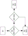
Fig. 3 shows a general form of a method for controlling the system 20, the method comprising the steps of:
s1-receiving a signal indicative of a current level of raw material contained in the material processing device 7;
s2 — determining whether the estimated level of unprocessed material contained in the material processing device 7 is below or above a first threshold value at the estimated arrival time of the first material handling vehicle 1 at the material processing device 7, based at least on the signal indicative of the current level of unprocessed material contained in the material processing device 7; and the number of the first and second groups,
s3-directing the first material handling vehicle 1 towards a first unloading target for unloading at the material processing device 7 when the estimated level of raw material contained in the material processing device 7 is below a first threshold; or
S4 — when the estimated level of raw material contained in the material processing device 7 is above the first threshold value, the first material handling vehicle 1 is directed towards a second unloading target for unloading at the local stockyard 8.
In this case, the first threshold value for the level of the raw material contained in the material processing device 7 is set to an upper limit value that does not allow additional raw material to be poured into the material processing device 7. If the level is above the upper limit value, it must wait until the level drops to or below the upper limit value before being allowed to dump more material into the processing device 7, so that in order to avoid a waiting time when the level is above the first threshold value, it is usually decided to direct the first vehicle towards the local storage 8 and dump the material into the local storage 8.
The method is performed when the first material handling vehicle 1 has reached or is about to reach the destination decision point 10. To obtain preliminary results and make preliminary decisions, the method is also performed before the first material handling vehicle 1 has reached or is about to reach the destination decision point 10.
The method may comprise the following steps which may be considered to be comprised in a variant of step S2:
s21-receiving a signal indicative of the current geographic location of the first material carrying vehicle 1;
s22-determining the distance between the first material carrying vehicle 1 and the material processing device 7 based on the current geographic location of the first material carrying vehicle 1 and information about available routes and the geographic location of the material processing device 7; and
s23 — determining an estimated time of arrival of the first material carrying vehicle at the material processing device 7 based on the distance between the first material carrying vehicle 1 and the material processing device 7 and the expected average speed of the first material carrying vehicle 1.
The steps S21 to S23 may be performed, for example, by: providing the first vehicle 1 with a GPS system; storing data on available routes (in this case there may be only one single route), the geographical location of the material processing device 7 and an expected average speed (which may be a preset default speed) in a memory accessible to the control unit 12; and the control unit 12 is configured to calculate said estimated time of arrival. All of which are known per se.
The method may also comprise the following steps which may be considered to be comprised in another variant of step S2:
s24-providing information indicating a desired processing rate of the material processing device 7, an
S25 — determining an estimated level of unprocessed material contained in the material processing device 7 at the estimated arrival time of the first material handling vehicle 1 at the material processing device 7 based on the expected processing rate of the material processing device 7.
The expected processing rate may be a preset standard or average processing rate (e.g. given in tons/hour) of the material crushing device 7 and may be pre-stored in a memory accessible to the control unit 12.
In particular when the first material carrying vehicle 1 is close to the destination decision point 10, when the decision point 10 is relatively close to the processing device 7 and when there is no further material carrying vehicle in front of the first material carrying vehicle 1 (which further material carrying vehicle is however in the form of a second vehicle 2 in fig. 2), the estimated level of the raw material may be set to the current level of the raw material and the estimated time of arrival of the first material carrying vehicle 1 may be set to the current point in time without losing too much precision. Then, steps S21 to S25 may be omitted, and step S2 may be simplified because determining whether the estimated level of unprocessed material contained in the material processing device 7 at the estimated arrival time of the first material carrying vehicle 1 at the material processing device 7 is below or above the first threshold value may be performed by: it is determined whether the current level of raw material contained in the material processing device 7 is below or above the first threshold value 1.
In order to consider another carrier vehicle in front of the first material carrier vehicle 1, the method may comprise the following steps which may be considered to be comprised in a further variant of step S2:
s26 — determine whether a second material carrier vehicle 2, which also transports material of unprocessed material to the second location 6, is in front of the first material carrier vehicle 1 and has been directed towards the first unloading target for unloading at the material processing device 7 (this has been shown in fig. 2); and, when so, the first and second substrates,
s27-receiving a signal indicating the amount of material to be unloaded by the second material handling vehicle 2 to the material processing device 7; and
s28-when it is determined whether the estimated level of unprocessed material contained in the material processing device 7 at the estimated arrival time of the first material carrying vehicle 1 at the material processing device 7 is below or above the first threshold value, material to be unloaded by the second material carrying vehicle 2 to the material processing device 7 is included.
As described above, the second vehicle 2 may send information about its position and its weight of material to the first vehicle 1. By including the material to be dumped by the second vehicle 2 in step S28, it is possible to direct the first vehicle 1 towards the local stockpile 8 instead of towards the processing device 7 even if the current level of the material is below the first threshold (e.g. if it is calculated that the material to be dumped by the second vehicle 2 would raise the material level above the first threshold).
Fig. 3 also indicates that some or all of steps S21-S28 may be included in step S2.
In order to take into account another material carrying vehicle after the first material carrying vehicle 1, the method may comprise the following steps, which are preferably performed if the fill level is determined in step S2 to be above the first threshold value, but which need not be performed if the fill level is below the threshold value (since in this case the first material carrying vehicle 1 is guided to the processing device 7 anyway):
s51 — determining an estimated arrival time for the third material carrying vehicle 3 to arrive at the material processing device 7, which third material carrying vehicle 3 also transports or is to transport material of unprocessed material to the second location 6, and is the next material carrying vehicle after the first material carrying vehicle 1 to arrive at the second location 6;
s52 — for the case where the material of the first material carrying vehicle 1 is not unloaded at the material processing device 7, determining whether the estimated level of unprocessed material contained in the material processing device 7 at the estimated arrival time of the third material carrying vehicle 3 at the material processing device 7 is below a second threshold; and
s53 — when the estimated level of unprocessed material contained in the material processing device 7 at the estimated arrival time at which the third material carrier vehicle 3 arrives at the material processing device 7 is below the second threshold, directing the first material carrier vehicle 1 toward the first unloading target to be unloaded at the material processing device 7 even if the estimated level of unprocessed material contained in the material processing device 7 at the estimated arrival time at which the first material carrier vehicle 1 arrives at the material processing device 7 is above the first threshold; or
S54-when the estimated level of raw material contained in the material processing device 7 is above a second threshold at the estimated arrival time of the third material carrier vehicle 3 at the material processing device 7, directing the first material carrier vehicle 1 towards a second unloading target for unloading at the local stock area 8.
Fig. 4 shows a variant of the method comprising steps S51 to S54.
In this case, the second threshold value for the level of raw material contained in the material processing device 7 is set to a lower limit value indicating that the material processing device has been depleted or is about to be depleted of raw material.
If there is a relatively long distance between the first vehicle 1 and the third vehicle 3 (much longer than shown in the schematic illustration 2), or at least if a relatively long period of time will elapse before the third vehicle 3 arrives, the first vehicle 1 may be guided towards the processing device 7 according to step S53, even if the current or estimated level of raw material contained in the material processing device 7 is above the first threshold value at the estimated arrival time of the first material handling vehicle 1 at the material processing device 7. In this way, the first vehicle 1 may need to wait some time before unloading at the processing device 7, but this is generally better than risking: that is, the processing device 7 is depleted of material before the third vehicle 7 arrives.
It is to be understood that the invention is not limited to the embodiments described above and shown in the drawings; rather, one of ordinary skill in the art appreciates that various modifications and changes can be made within the scope of the claims set forth below.