Detailed Description
The technical solution in the present application will be described below with reference to the accompanying drawings.
The terminology used in the following examples is for the purpose of describing particular embodiments only and is not intended to be limiting of the application. As used in the specification of the present application and the appended claims, the singular forms "a", "an", "the" and "the" are intended to include the plural forms as well. Such as the expression "one or more" unless the context clearly indicates otherwise. It should also be understood that in the following embodiments of the present application, "at least one", "one or more" means one, two or more.
Reference throughout this specification to "one embodiment" or "some embodiments," or the like, means that a particular feature, structure, or characteristic described in connection with the embodiment is included in one or more embodiments of the present application. Thus, appearances of the phrases "in one embodiment," "in some embodiments," "in other embodiments," or the like, in various places throughout this specification are not necessarily all referring to the same embodiment, but rather "one or more but not all embodiments" unless specifically stated otherwise. The terms "comprising," "including," "having," and variations thereof mean "including, but not limited to," unless expressly specified otherwise.
The technical scheme of the embodiment of the application can be applied to ASON. Fig. 1 is a schematic diagram of an ASON provided in an embodiment of the present application.
The ASON may include a plurality of ASON nodes (such as node #1, node #2, node #3, and node #4 shown in fig. 1), where each ASON node acquires information of other nodes in the ASON through an Open Shortest Path First (OSPF) protocol, where the information of the node includes a node identifier and/or a link identifier.
For example, the node #1 shown in fig. 1 acquires information such as node identifications and/or link identifications of the node #2, the node #3, and the node #4 shown in fig. 1, respectively, through the OSPF protocol; similarly, the node #2 shown in fig. 1 acquires information such as node identifiers and/or link identifiers of the node #1, the node #3, and the node #4 shown in fig. 1 through the OSPF protocol, the node #3 shown in fig. 1 acquires information such as node identifiers and/or link identifiers of the node #1, the node #2, and the node #4 shown in fig. 1 through the OSPF protocol, and the node #4 shown in fig. 1 acquires information such as node identifiers and/or link identifiers of the node #1, the node #2, and the node #3 shown in fig. 1 through the OSPF protocol.
After each ASON node in the ASON acquires information of other nodes in the ASON, a path of an end-to-end service may be determined through a Constrained Shortest Path First (CSPF) algorithm, and finally, establishment of the end-to-end service path is completed through an RSVP-TE protocol.
For ease of understanding, the several basic concepts involved in the ASON described above are briefly introduced:
1. and (4) nodes.
For representing a hardware entity in an ASON. For example, a node may be understood as a transport network device. The ASON shown in fig. 1 includes four nodes, i.e., node #1, node #2, node #3, and node # 4.
It should be understood that the ASON shown in fig. 1 is only an example, and does not limit the scope of the present application in any way. The number of nodes included in the ASON may be 4 or more, or the number of nodes included in the ASON may be 2 or more.
2. An interface.
The node has a physical port for sending and/or receiving information, which is referred to as an interface in this application, where the information sent and/or received by the node through the interface may include network protocol messages, traffic data, and the like.
There are 8 interfaces in the ASON shown in fig. 1: interface #1, interface #2, interface #3, interface #4, interface #5, interface #6, interface #7 and interface #8, respectively, where interface #1 and interface #8 are physical ports of node #1, interface #2 and interface #3 are physical ports of node #2, interface #4 and interface #5 are physical ports of node #3, and interface #6 and interface #7 are physical ports of node # 4.
It should be noted that the physical ports of the nodes shown in fig. 1 are only examples, and the scope of the present application is not limited in any way, for example, the node #1 shown in fig. 1 may have only one physical port and perform the function of receiving and/or transmitting information with the nodes #2 and # 4.
3. And (4) links.
In the embodiment of the present application, a connection between two adjacent nodes is referred to as a link. A link may be represented by a link (node-interface ), and whether a link exists between two adjacent nodes may be used to indicate whether information such as network protocol messages and/or traffic data can be forwarded between the two adjacent nodes, for example, if a link exists between two adjacent nodes, information such as network protocol messages and/or traffic data can be forwarded between the two adjacent nodes; similarly, if there is no link between two adjacent nodes, information such as network protocol messages and/or traffic data cannot be forwarded between the two adjacent nodes.
For example, the links (node # 1-interface #1, node # 2-interface #2) indicate that information such as network protocol messages and/or traffic data can be received at node #2 and interface #2 after being sent from interface #1 of node # 1.
There are 8 links in the ASON shown in fig. 1: link 1-2 (node # 1-interface #1- > node # 2-interface #1), link 1-4 (node # 1-interface #8- > node # 4-interface #7), link 2-1 (node # 2-interface #2- > node # 1-interface #1), link 2-3 (node # 2-interface #3- > node # 3-interface #4), link 3-2 (node # 3-interface #4- > node # 2-interface #3), link 3-4 (node # 3-interface #5- > node # 4-interface #6), link 4-3 (node # 4-interface #6- > node # 3-interface #5), link 4-1 (node # 4-interface #7- > node # 1-interface # 8).
4. A traffic path.
The traffic path may include a working path, a recovery path, a protection path, etc. for carrying data transmission of the traffic. A traffic path is a route between a first node and a last node, between which one or more nodes may exist. The first node of the service path represents a sending node of data in the connection, and the last node of the service path represents a receiving node of the data in the connection. A traffic path may be represented by traffic (head-end node), and the presence or absence of a traffic path between the head node and the end node may be used to indicate whether data can be sent from the head node to the end node. If a service path exists between the first node and the last node, the data can be sent to the last node from the first node; similarly, if there is no traffic path between the head node and the end node, the data cannot be sent from the head node to the end node. The connection between the first node and the last node formed by the traffic path or the transmission data carried on the traffic path may be referred to as traffic.
For example, the ASON shown in fig. 1 has services 1-3, which means that there is a connectable data channel between node #1 and node #3 for transmitting data from node #1 to node #3, and the data channel may be referred to as a path, i.e., a data transmission path.
Since a traffic path represents a route between a first node to a last node, it may also be referred to as an end-to-end traffic path, where "end-to-end" represents the first node to the last node.
5. RSVP-TE protocol.
ASON may provide end-to-end establishment, query, deletion, attribute modification and restoration functions of a traffic path through RSVP-TE protocol, where end-to-end may be understood as one node to another.
The end-to-end establishment of the traffic path comprises: the network management issues a service path establishing command to the first node, then the first node realizes the routing calculation and initiates a service path configuration process through an RSVP-TE signaling protocol, and cross connection is established point by point from the first node to a downstream node, thereby completing the end-to-end establishment of the service path.
The end-to-end establishment of the service path fully utilizes the routing and signaling functions of each node, and shortens the configuration time of the service path. As in fig. 1, the specific steps of initiating service 1-3 establishment via RSVP-TE signaling protocol include:
the network manager issues a service 1-3 creation command to the first node #1, and the first node #1 determines that the service path of the service 1-3 is as follows through the CSPF: node # 1-node # 2-node #3, where the head node #1 sends a Path message to the neighboring node #2 through the link 1-2 (node # 1-interface #1- > node # 2-interface #2) along the determined traffic Path, and specifically, the interface #1 of the node #1 sends the Path message (the Path message is one of RSVP-TE protocol packets) to the interface #2 of the intermediate node # 2;
after receiving the Path message, the node #2 solves the cross configuration association information of the node #2 and establishes reverse cross connection, and then the intermediate node #2 sends the Path message to the adjacent node #3 through the link 2-3 (node # 2-interface #3- > node # 3-interface #4), specifically, the interface #3 of the node #2 sends the Path message to the interface #4 of the end node #3, and similarly, the corresponding cross configuration message is solved at the end node #3 and local reverse cross connection is established.
The end node #3 sends a reserved request (Resv) message (one of the Resv messages RSVP-TE protocol messages) to the direction of the head node #1 via the intermediate node #2, and establishes forward cross-connections at each node along the way; in the same process, the head node #1 sends a Path message to the end node #3 via the intermediate node #2, opens the alarm monitoring of the traffic Path along the way, and the end node #3 sends a Resv message to the head node #1 via the intermediate node #2 for confirmation.
The whole process of end-to-end establishment of the service path is automatically completed by RSVP-TE signaling to complete the end-to-end configuration establishment of services 1-3.
It should be understood that fig. 1 is only an example of a scenario in which the present application can be applied, and the scope of protection of the present application is not limited in any way, and the method for restoring path configuration provided in the embodiment of the present application may also be applied in other scenarios. Such as other optical transmission networks.
In case of network fiber break in the ASON shown in fig. 1, the nodes in the ASON may implement the service path restoration through RSVP-TE protocol. How to implement the service path restoration in the case of a fiber break in the ASON shown in fig. 1 will be briefly described below with reference to fig. 2 and 3.
Fig. 2 is a schematic diagram of a traffic path restoration, and the node shown in fig. 2 can implement end-to-end automatic restoration of the traffic path through RSVP-TE protocol.
As can be seen from fig. 2, the automatic establishment of the original traffic path of the traffic 1-3 by the traffic 1-3 via RSVP-TE is: node # 1-node # 2-node #3, wherein the original traffic path may also be referred to as the working path. If the optical fiber between the node #1 and the node #2 is interrupted, the implementing of the end-to-end service path automatic recovery through the RSVP-TE protocol comprises the following steps:
the node #2 senses the fault warning information, searches the affected service 1-3 according to the port warning information carried in the fault warning information in a matching manner, and then notifies the fault information to a first node (node #1) of the affected service 1-3 through an RSVP notification (Notify) message.
It should be noted that how the node #2 senses the fault alarm information in the embodiment of the present application is not limited, and may be that after the optical fiber between the node #1 and the node #2 is broken (e.g., the optical fiber in the direction from the node #1 to the node #2 is broken, and the optical fiber in the direction from the node #2 to the node #1 is not broken), the bottom layer of the node #2 senses the optical fiber break (e.g., senses the break of information transmission). In addition, how to transmit the RSVP notification message to the node #1 by the node #2 in the embodiment of the present application is not limited, and the RSVP notification message may be transmitted to the node #1 through an optical fiber in the direction from the node #2 to the node #1, or may be transmitted to the node #1 through another path in a case where the optical fiber in the direction from the node #2 to the node #1 is also interrupted.
After receiving the RSVP Notify message, the node #1 learns the affected services 1-3 through the failure information, and automatically determines a restoration path (such as the node # 1-the node # 4-the node #3 shown in fig. 2) that can continue to implement the services 1-3. Then the nodes in the ASON establish cross connection hop by hop along the service restoration Path (node # 1-node # 4-node #3) through RSVP-TE signaling (Path and Resv message), automatically complete the establishment of the end-to-end restoration Path, and after the establishment of the restoration Path is completed, the service 1-3 is automatically restored.
Fig. 3 is a diagram illustrating another traffic path restoration, and a node in the ASON shown in fig. 3 may implement the segment restoration of the traffic path through the RSVP-TE protocol.
As can be seen from fig. 3, the traffic 1-3 automatically establishes the original traffic path (node # 1-node # 2-node #3 as shown in fig. 3) of the traffic 1-3 through RSVP-TE signaling, wherein the original traffic path may also be referred to as a working path. Node #2 in fig. 3 may be referred to as a forking node and node #3 may be referred to as a merging node. If the optical fiber between the node #2 and the node #3 is interrupted, the segment recovery of the services 1-3 through the RSVP-TE protocol comprises the following steps:
node #2 and/or node #3 are aware of the fault alarm information (e.g., node #2 is aware of the fault alarm information). The node #2 finds the affected services 1-3 according to the port alarm information in the fault alarm information, and finds that the corresponding section recovery routing information is the node # 2-node # 4-node #3 as shown in fig. 3.
Then, a recovery cross connection is established hop by hop along a section recovery Path node # 2-node # 4-node #3 through an RSVP-TE signaling (Path and Resv message) initiating that a first node is a node #2 and a last node is a node #3, the establishment of the section recovery Path is automatically completed, after the establishment of the section recovery Path is completed, the service 1-3 is automatically recovered, and the end-to-end transmission Path of the first node (node #1) and the service 1-3 of the service 1-3 is notified to be switched (the node # 1-node # 2-node #3 is switched into the node # 1-node # 2-node # 4-node # 3).
In the service restoration method shown in fig. 2 and fig. 3, when the number of services in the ASON increases, the size of the rerouting packet increases with the increase of the number of services, so that the transmission performance is extended, and the performance of service path restoration gradually deteriorates. For example, if a fiber break occurs in 40 service paths in the ASON described in fig. 2, 40 times of the rerouting packet described in fig. 2 is required.
It should be noted that, the service path restoration may also be understood as service restoration, because after the service path restoration, the service carried on the service path may also be transmitted correspondingly.
The foregoing briefly introduces a scenario in which the method for restoring a path configuration provided by the embodiment of the present application can be applied, and introduces a basic concept that may be involved in the embodiment of the present application, with reference to fig. 1, and the following describes in detail the method for restoring a path configuration provided by the embodiment of the present application with reference to the accompanying drawings.
It should be noted that the method for restoring path configuration provided in the embodiment of the present application can be applied to ASON as shown in fig. 1 by way of example only, and the scope of protection of the present application is not limited in any way. The method for restoring path configuration provided by the present application can also be used in other optical transport networks, for example, GMPLS. In the case of being applied to other optical transmission networks except for the ASON, steps executed by nodes in the network are similar to those executed by nodes in the ASON in the case of being applied to the ASON, so for convenience of description, the method for restoring path configuration is mainly applied to the ASON in the embodiment of the present application, and is not described in detail in other scenarios.
It should also be understood that the embodiments shown below do not particularly limit the specific structure of the execution subject of the method provided by the embodiments of the present application, as long as the execution subject can communicate with the method provided by the embodiments of the present application by running the program recorded with the code of the method provided by the embodiments of the present application, for example, the execution subject of the method provided by the embodiments of the present application may be a device, or a functional module capable of executing the program in a core/metropolitan area device.
In order to improve the bulk service recovery performance, the application provides a method and a device for recovering path configuration. The services with the same recovery path are formed into a service group, and the recovery of the services is realized aiming at the service group, so that the batch service recovery performance is improved.
To facilitate understanding of the embodiments of the present application, the following description is made.
First, in the present application, "for indicating" may include for direct indication and for indirect indication. When a certain indication information is described for indicating a, the indication information may be included to directly indicate a or indirectly indicate a, and does not mean that a is necessarily included in the indication information.
If the information indicated by the indication information is referred to as information to be indicated, there are many ways to indicate the information to be indicated in the specific implementation process. For example, but not limited to, the information to be indicated may be directly indicated, such as the information to be indicated itself or an index of the information to be indicated. The information to be indicated can also be indirectly indicated by indicating other information, wherein an association relationship exists between the other information and the information to be indicated. It is also possible to indicate only a part of the information to be indicated, while the other part of the information to be indicated is known or predetermined. For example, the indication of the specific information may be implemented by means of a predetermined arrangement order of the respective information (e.g., protocol specification), thereby reducing the indication overhead to some extent. Meanwhile, the universal parts of all information can be identified and indicated in a unified mode, so that the indicating overhead caused by independently indicating the same information is reduced.
Second, the first, second and various numerical numbers (e.g., "# 1", "# 2") in this application are merely for convenience of description and are not intended to limit the scope of the embodiments of this application. For example, to distinguish between different nodes, to distinguish between different services, or to distinguish between different groups of services.
Third, in this application, "preset" may include being indicated by network device signaling, or predefined, e.g., a protocol definition. The "predefined" may be implemented by saving a corresponding code, table, or other means that can be used to indicate the relevant information in advance in the device (for example, including a node or a network device), and the present application is not limited to the specific implementation manner.
Fourth, the term "store" referred to in the embodiments of the present application may refer to a store in one or more memories. The one or more memories may be provided separately or integrated in the encoder or decoder, the processor, or the communication device. The one or more memories may also be provided separately, with a portion of the one or more memories being integrated into the decoder, the processor, or the communication device. The type of memory may be any form of storage medium and is not intended to be limiting of the present application.
Fifth, the "protocol" referred to in the embodiment of the present application may refer to a standard protocol in the optical transmission field, and for example, may include a protocol referred to in ASON, a protocol referred to in GMPLS, and a related protocol applied in the future optical transmission field, which is not limited in the present application.
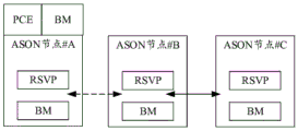
Fig. 4(a) is a schematic flow chart of a method for restoring path configuration provided in the present application. The method can be applied to ASON, where the ASON includes a plurality of nodes, as shown in fig. 4(b), and fig. 4(b) is used to show a schematic node configuration diagram in the ASON to which the embodiment of the present application can be applied.
A plurality of nodes included in the ASON have ASON functions, and as can be seen from fig. 4(b), each node deploys a Bundle Mapping (BM) processing unit and a resource reservation protocol (RSVP) control unit.
The ASON includes therein network equipment for path computation. Illustratively, the network device includes a PCE controller, i.e., at least one PCE controller is disposed in the ASON. Or, illustratively, the network device includes a node having a path computation function. For example, at least one node in the ASON is deployed with a PCE controller; also for example, at least one node in the ASON is deployed with a path computation function module.
In this embodiment, the network device is configured to determine, when a failure occurs in a working path that carries multiple services in an ASON, a restoration path corresponding to the working path that carries the multiple services, mark the restoration paths having the same restoration path segment as a group of restoration paths, and generate, for the group of restoration paths, a first ID indicating that service restoration is performed on the working paths corresponding to the group of restoration paths respectively by using the restoration path segment.
The ID referred to in this embodiment may be understood as identification information for identifying a group of restoration paths, and in this embodiment, the identification information index (index) or indication information may also be referred to as an ID for convenience of description.
It should be noted that the correspondence between the restoration path and the working path means that, when the working path fails, the restoration path is used for performing service restoration on the service carried on the working path, and it may also be understood that the restoration path is the same as the service carried on the working path, and the ID identified as a group of restoration paths is understood from this point of view. Further, it may be understood that the identifier is an ID of a service carried on a working path corresponding to each of a group of restoration paths, and therefore the ID may also be referred to as a service group ID in this embodiment of the application, and is used to identify a group of services.
The "restoration path corresponding to the working path" referred to in the following text means that the restoration path performs service restoration on the service carried on the working path, and the "restoration path corresponding to the service" means the service that can be restored by the restoration path.
The BM processing unit manages IDs, for example, by adding, deleting, or updating.
The RSVP control unit can manage the establishment, deletion or update of the service group ID of a single service; after failure, the affected service group ID is determined and link establishment is initiated.
It should be understood that fig. 4(b) is a schematic diagram provided for facilitating understanding of the present application, and the protection scope of the present application is not limited in any way, and names of the various units described above are also merely examples, and other units or modules capable of achieving the same function may be substituted for the units shown in fig. 4 (b).
In this embodiment, a first service group is formed by two services (a first service and a second service), in which a node with a path computation function and a PCE controller are collectively referred to as a network device, in this embodiment, the first service is carried in a first working path, a first node of the first working path is referred to as a first node, the second service is carried in a second working path, and the first node of the second working path is referred to as a second first node.
It should be noted that the first working path and the second working path may be the same working path, that is, the working path carries multiple services. In addition, the first restoration path corresponding to the first working path and the second restoration path corresponding to the second working path may also be the same restoration path, and the restoration path may restore multiple services carried on a certain working path.
Fig. 4(a) the method for restoring path configuration at least includes all or part of the following steps:
s410, the network device determines a restoration path.
Specifically, the network device determines a first restoration path of a first working path and a second restoration path of a second working path, where the first restoration path is used to perform service restoration on the first working path when the first working path fails, the second restoration path is used to perform service restoration on the second working path when the second working path fails, and the first restoration path and the second restoration path have the same restoration path segment.
In the embodiment of the application, the network device can acquire services and topology in the network, determine the recovery path corresponding to the working path for carrying the services based on the fault link and the recovery path policy, bind and associate a plurality of services with the same recovery path segment through the service group ID, and the service group ID identifies that the recovery paths corresponding to the plurality of services have the same recovery path segment.
The failed link and restoration path policy means that when the network device determines restoration paths corresponding to working paths affected by a failed link on the premise that a link in the network fails, the multiple restoration paths have the same restoration path segment as much as possible.
The same restoration path segment referred to in the embodiment of the present application is a common partial path segment or an overlapping partial path segment of the first restoration path and the second restoration path, and may also be understood as an overlapping restoration path segment, a shared restoration path segment, and the like, and is hereinafter referred to as a restoration path segment for short. The first restoration path and the second restoration path have the same restoration path segment, and the same restoration path segment may be a partial path segment of the first restoration path or the second restoration path, or may be an entire path segment of the first restoration path or the second restoration path.
In the embodiment of the present application, a specific reason why the working path fails is not limited. The failure of the first working path may be a failure of one or more links in the first working path, a failure of a node on the first working path, a failure of an interface of a node on the first working path, or the like; similarly, the failure of the second working path includes a failure of one or more links in the second working path, a failure of a node on the second working path, a failure of an interface of a node on the second working path, and the like.
As a possible implementation manner, the failed link on the first working path is the same as the failed link on the second working path. For example, the first working path and the second working path have the same first link, and when the first link fails, both the first working path and the second working path fail, and in this embodiment, the failed first link is referred to as a first failed link.
Illustratively, the failure of the first link may be a failure of at least one of the two nodes on the first link, a failure of an interface of at least one of the two nodes on the first link, or a failure (e.g., a fiber break) of an optical fiber between the two nodes on the first link.
Further, after the network device determines the first restoration path and the second restoration path having the same restoration path segment, the network device generates a first ID indicating that the service restoration is performed on the first working path and the second working path by using the restoration path segment. The first ID may indicate that multiple services on the restoration path segment perform service restoration at the same time, or may indicate that multiple restoration paths on the restoration path segment perform service restoration at the same time, which is equivalent to compressing messages of multiple services or multiple restoration paths into one message, so that the efficiency of service restoration may be improved.
That is, the method flow shown in fig. 4 further includes S420, generating the first ID.
The first ID indicates that the first working path and the second working path are subjected to service restoration by adopting the restoration path section.
It should be understood that, the first restoration path is used to restore the first service carried on the first working path, and the second restoration path is used to restore the second service carried on the second working path, which may be understood as a first ID used to identify a service group formed by the first service and the second service, and in this embodiment, the ID may be referred to as a service group ID.
For example, the first working path may be referred to as an original path carrying the first traffic, and the second working path may be referred to as an original path carrying the second traffic. The first service may include one or more services and the second service may also include one or more services.
The network device may determine at least one restoration path for restoration of a certain service based on different failed links in the working path carrying each service in the network.
As a possible implementation manner, if a link in the network fails, the link affects transmission of multiple services, and restoration paths corresponding to working paths respectively carrying the multiple services have the same restoration path segment, and the network device may group the multiple services into a service group and generate an ID of the service group.
As another possible implementation manner, if multiple links in the network fail, the multiple links respectively affect multiple service transmissions, and recovery paths corresponding to working paths respectively carrying the multiple services have the same recovery path segment, the network device may group the multiple services into a service group and generate an ID of the service group.
It should be noted that, the possibility that multiple links in the network fail simultaneously or at short intervals is low, and generally, when a certain link fails, multiple services are simultaneously affected, so the embodiment of the present application mainly relates to a scenario where multiple service transmissions are affected when a certain link in the network fails. However, the method for restoring path configuration provided by the present application is not limited to be applicable to a scenario where multiple links in a network have a failure, and application flows in different application scenarios are similar, and for convenience of description, a case where a failure occurs in a certain link in the network (e.g., a first failed link) and affects multiple services is mainly taken as an example for description hereinafter.
After the network device generates the first ID, it needs to notify the first ID to a head node (a third node shown in fig. 4 (a)) of the restoration path segment, and the method flow shown in fig. 4(a) further includes S430, where the network device sends a first configuration message to the third node, where the first configuration message carries the first ID.
Illustratively, the first configuration message may be a path computation element communication protocol (PCEP) message, or the first configuration message may be a protocol message having the same function as the PCEP, or the first configuration message may be implemented by a field (e.g., an extended PCEP field) added in original signaling between the network device and the head node of the restoration path segment.
Further, the network device may also notify the first node of the recovered path segment of the routing information of the recovered path segment (e.g., the third node shown in fig. 4 (a)), and then the method flow shown in fig. 4(a) further includes S431, where the network device sends a second configuration message to the third node, where the second configuration message carries the routing information of the recovered path segment.
The second configuration message may be a PCEP message, or the second configuration message may be a protocol message having the same function as PCEP, or the second configuration message may be implemented by a field (e.g., an extended PCEP field) added in original signaling between the network device and the head node of the restoration path segment.
It should be noted that the first configuration message and the second configuration message may be the same message, or the first configuration message and the second configuration message may be two different messages, which is not limited in this application.
In this embodiment of the application, the first ID may also be notified to the first head node of the first working path and the second head node of the second working path, and specifically based on the identity of the network device in the network, the following manners are divided into:
the first method is as follows: the network equipment is PCE
The network device is a PCE controller set up in the network, and the PCE controller is a device deployed independently of the head node of the above-mentioned working path and the head and end nodes of the restoration path segment.
In the first mode, after the network device generates the first ID, it needs to notify the first ID to the head nodes of the first working path and the second working path, and then the method flow shown in fig. 4(a) further includes S432, where the network device sends the first message and S433 to the first head node, and the PCE node sends the second message to the second head node.
The first message and the second message may be understood as PCEP messages, or protocol messages that implement similar functions to PCEP messages, or some signaling that is already between the PCE controller and the node.
By way of example and not limitation, the first head node and the second head node may be the same node, that is, the head nodes of the first working path and the second working path are the same, and the first message and the second message may be the same message sent to the same node in the network.
The first message and the second message at least need to include the first ID, so that the head node of the first working path and the second working path knows the first ID.
Further, the first message may further include at least one of an identifier of the first service, an identifier of the first failed link, and routing information of the first restoration path; the second message may further include at least one of an identification of the second traffic, an identification of the first failed link, and routing information of the second restoration path. The identifier of the first service may be a Label Switch Path (LSP) ID of the first service, and the identifier of the second service may be an LSP ID of the second service. In the embodiment of the present application, the identifier of the failed link is not limited, and reference may be made to an identifier scheme of the failed link in the existing optical transmission field, for example, the failed link is a link between a third node and a fourth node, and the identifier of the failed link may be the failed link from the third node to the fourth node.
The first message may be a single message or a collective name of multiple messages, that is, the first ID, the identifier of the first service, the identifier of the first failed link, and the routing information of the first restoration path may be sent to the first head node through a single message, or may be sent to the first head node through multiple messages; similarly, the second message may be a single message or may be a collective name of multiple messages, that is, the first ID, the identifier of the second service, the identifier of the first failed link, and the routing information of the second restoration path may be sent to the second head node through a single message, or may be sent to the second head node through multiple messages.
It should be noted that, when the first message does not carry the identifier of the first service, it is indicated that the first head node can determine that the first head node is the head node of the first working path carrying the first service. For example, if the first head node is used as the head node of one working path, the first head node can still know the first service carried on the first working path even if the first message does not carry the identifier of the first service after receiving the first message. If the first head node can be used as the head node of multiple working paths, and the services carried by the multiple working paths are different, the first message needs to carry the identifier of the first service.
When the first message does not carry the identifier of the first failed link, it is indicated that the first head node can determine that the failed link is the first link, for example, the first head node learns the first working path and the first restoration path, and by comparing node changes on the first working path and the first restoration path, the failed first link can be inferred.
When the first message does not carry the routing information of the first restoration path, it is indicated that the first head node can determine the first restoration path, for example, the first head node learns the first working path and the first failed link, and locally calculates to obtain the first restoration path.
The second message does not carry the identifier of the second service, the identifier of the first failed link, or the routing information of the second restoration path, and the first message does not carry the identifier of the first service, the identifier of the first failed link, or the routing information of the first restoration path, which are similar to each other and are not described herein again.
Further, the first message and/or the second message may also carry routing information of the restoration path segment, so that the first head node and/or the second head node knows which restoration path segment the first ID indicates to use for service restoration of the first working path and the second working path.
The first ID and the routing information of the restoration path segment in the embodiment of the present application may be referred to as extended TLV information. TLVs are a variable format meaning: type (Type), Length (Length), Value (Value), wherein the Type field is information about a tag and an encoding format; the Length field is the Length of the defined value; the Value field indicates the actual Value. The Length of Type and Length is typically fixed, e.g., 2 or 4 bytes.
The message formats of the first message and the second message related in the present application may be as follows:
<PCUpd Message>::=<Message Common Header>
< SRP object >
< LSP object >
Service group ID TLV attribute, TLV information of service group ID bound and mapped by new added service, byte length is 4 bytes "
< ERO subject >
Adding < section recovery path > TLV' optional information: TLV information of segment restoration path corresponding to service group ID "
A message format of the service group ID is shown in fig. 5, fig. 5 is a schematic diagram of a first ID message format provided in the embodiment of the present application, and the field meanings and values included in fig. 5 are shown in table 1 below.
TABLE 1
| Name of field
|
Means of
|
Value taking
|
| Type
|
TLV type, newly added service group ID type
|
A 16bit digital value
|
| Length
|
TLV length in bytes.
|
A 16bit value
|
| Service Group ID
|
Service group ID
|
A 32bit digital value |
The information format of the reclosure recovery path is shown in fig. 6, fig. 6 is a schematic diagram of a routing information format of a recovery path segment provided in an embodiment of the present application, and the meaning and value of the fields included in fig. 6 are shown in table 2 below.
TABLE 2
After the network device notifies the first head node and the second head node of the first ID, in order to quickly implement service restoration in the subsequent service restoration process in the first mode, resources may be preconfigured for nodes on the restoration path segment, so that when the first working path and the second working path fail, the nodes on the restoration path segment may quickly implement service restoration based on the preconfigured resources.
The node resource pre-configuration on the recovery path segment in the first mode includes the following two possibilities, which can be implemented in an optional one of the following possible modes:
it is possible that the network device pre-configures resources for nodes on the recovery path segment.
In a possible case, the method flow shown in fig. 4(a) further includes S440, where the network device sends a third configuration message to nodes (such as the third node, the fourth node, and the fifth node shown in fig. 4 (a)) on the recovery path segment, where the third configuration message carries the channel resource of the recovery path segment in the first recovery path and the channel resource of the recovery path segment in the second recovery path.
Illustratively, the third configuration message may be a PCEP message, or the third configuration message may be a protocol message having the same function as PCEP, or the third configuration message may be implemented by a field (e.g., an extended PCEP field) added in signaling transmitted by the network device along the recovery path segment.
Further, the third configuration message may further include at least one of an identifier of the first service, an identifier of the second service, routing information of the restoration path segment, and the first ID.
It can be understood that, in the case that the third configuration message includes the first ID, the network device may not need to send the first configuration message to the head node of the restoration path segment; similarly, when the third configuration message includes the route information of the recovered path segment, the network device may not need to send the second configuration message to the head node of the recovered path segment. The third configuration message may also carry the first ID and the route information of the restoration path segment, in which case it may be understood that the first configuration message and the second configuration message need not be sent, or it may be understood that the first configuration message, the second configuration message, and the third configuration message are the same message (e.g., the third configuration message carries the first ID, the route information of the restoration path segment, and the channel resource of the restoration path segment in the first restoration path and the channel resource of the restoration path segment in the second restoration path).
It should be noted that the third node is a first node on the restoration path segment, the fourth node is a last node on the restoration path segment, the fifth node is an intermediate node on the restoration path segment, and the fifth node may be multiple nodes, that is, multiple intermediate nodes on the restoration path segment.
The third configuration message format may be as follows:
<PCUpd Message>::=<Message Common Header>
< SRP object >
< LSP object > "extended flag operation type New LSP Pre-configuration type"
Service group ID TLV attribute, TLV information of service group ID bound and mapped by new added service, byte length is 4 bytes "
< ERO subject >
The message format of the first ID is shown in fig. 5, and the meaning and value of the fields included in fig. 5 are shown in table 1 and are not described herein again.
The third configuration message format is shown in fig. 7. Fig. 7 is a schematic diagram of a third configuration message format provided in an embodiment of the present application, where the meaning and value of the fields included in fig. 7 are shown in table 3 below.
TABLE 3
And probably two, the first node of the working path pre-configures the resource for the node on the recovery path segment. If the first head node and the second head node pre-configure the resources for the nodes on the recovered path segment, in a possible second case, the method flow illustrated in fig. 4(a) further includes S441, where the first head node sends a fifth configuration message to the nodes on the recovered path segment (such as the third node, the fourth node, and the fifth node illustrated in fig. 4 (a)), and the fifth configuration message carries the channel resources of the recovered path segment in the first recovered path.
Illustratively, the fifth configuration message may further include an identifier of the first service and/or the first ID.
It is to be understood that, in the case where the first ID is included in the fifth configuration message, the network device may not need to send the first configuration message to the head node of the restoration path segment.
Illustratively, the fifth configuration message may be an RSVP Path message, a message functionally similar to the RSVP Path message, or other signaling transmitted by the first head node along the first restoration Path.
It should be noted that, the first node may also send the fifth configuration message to other nodes (nodes other than the node on the restoration path segment) on the first restoration path, and since the embodiment of the present application mainly relates to the step of executing the node on the restoration path segment in the case that the first link fails, details included in the fifth configuration message received by the other nodes on the first restoration path are not repeated.
Similarly, the method flow illustrated in fig. 4(a) may further include S442, where the second head node sends a sixth configuration message to nodes (such as the third node, the fourth node, and the fifth node shown in fig. 4 (a)) on the recovery path segment, and the sixth configuration message carries the channel resource of the recovery path segment in the second recovery path.
Illustratively, the sixth configuration message may further include an identifier of the second service and/or the first ID.
It is to be understood that, in the case where the first ID is included in the sixth configuration message, the network device may not need to send the first configuration message to the head node of the restoration path segment.
Illustratively, the sixth configuration message may be an RSVP Path message, a message functionally similar to the RSVP Path message, or other signaling transmitted by the second head node along the second restoration Path.
It should be noted that, the second first node may also send the sixth configuration message to other nodes (nodes other than the node on the restoration path segment) on the second restoration path, and since the embodiment of the present application mainly relates to the step of executing the node on the restoration path segment in the case that the first link fails, details included in the sixth configuration message received by the other nodes on the second restoration path are not described again.
The fifth configuration message or the sixth configuration message is specifically in the following format:
the message format of the first ID is shown in fig. 5, and the meaning and value of the fields included in fig. 5 are shown in table 1 and are not described herein again.
The fifth configuration message or the sixth configuration message format is implemented by extending the HOP type as shown in fig. 8. Fig. 8 is a schematic diagram of a message format of a fifth configuration message or a sixth configuration message provided in an embodiment of the present application, where meanings and values of fields included in fig. 8 are shown in table 4 below.
TABLE 4
The method for restoring path configuration provided by the application can also be used for configuring the path restoring capability for the first node and the last node on the restoring path segment.
It should be noted that, in the embodiment of the present application, there is no limitation on the precedence relationship between configuring the path restoration capability for the first node and the end node on the restoration path segment and pre-configuring the resource for the node on the restoration path segment. For example, the path restoration capability may be configured for the first node and the last node on the restoration path segment, and then the resource may be preconfigured for the node on the restoration path segment; for example, the node on the recovery path segment may be preconfigured with resources first, and then the first node and the last node on the recovery path segment may be configured with the path recovery capability; also for example, the pre-configuration of resources for nodes on a recovery path segment and the configuration of path recovery capabilities for the head node and the tail node on the recovery path segment may be performed simultaneously.
Specifically, in the first mode, configuring the restoration capability for the head node and the end node on the restoration path segment in the embodiment of the present application includes the following two possibilities, which may be implemented in any optional one possible mode:
possibly, the network device configures a path restoration capability for a first node and a last node on a restoration path segment, in a first mode, the method flow in fig. 4(a) further includes S450, the network device sends a fourth configuration message to end nodes (such as a third node and a fourth node shown in fig. 4 (a)) of the restoration path segment, where the fourth configuration message carries a type of the end node, the type of the end node includes the first node of the restoration path segment and the last node of the restoration path segment, and the first node of the segment of the restoration path or the last node of the restoration path segment has the path restoration capability.
Wherein the end node type can be used to determine that the end node is path restoration capable. For example, after the first node of the recovered path segment receives the fourth configuration message, the first node of the recovered path segment can determine that the first node has the path recovery capability based on the end node type of the first node; for example, the end node can determine that it has path restoration capability for the end node of the restoration path segment based on its end node type after receiving the fourth configuration message.
Illustratively, the fourth configuration message may be a PCEP message, or the fourth configuration message may be a protocol message having the same function as PCEP, or the fourth configuration message may be implemented by a field (e.g., an extended PCEP field) added in signaling transmitted by the network device along the recovery path segment.
Further, the fourth configuration message may further include at least one of an identifier of the first failed link, routing information of the restoration path segment, an identifier of the first service, an identifier of the second service, and the first ID.
When the fourth configuration message includes the identifier of the first failed link and the routing information of the recovered path segment, after receiving the fourth configuration message, the third node may store the identifier of the first failed link, the routing information of the recovered path segment, and an identifier indicating that the third node has a path recovery capability based on its own end node type, where the identifier indicating that the third node has the path recovery capability may be an identifier of a head node of the recovered path segment or another field;
similarly, after receiving the fourth configuration message, the fourth node may store the identifier of the first failed link, the routing information of the recovered path segment, and the identifier indicating that the fourth node has the path recovery capability based on the end node type of the fourth node, where the identifier indicating that the fourth node has the path recovery capability may be an identifier of an end node of the recovered path segment or another field.
The third configuration message and the fourth configuration message may be the same message, or the third configuration message and the fourth configuration message may be two different messages, which is not limited in this application.
For example, when the node where the first failed link is located does not have the service restoration capability, the network device may further send an identifier of the first node of the restoration path segment (e.g., an identifier of the third node) to the node where the first failed link is located, and notify the node where the first failed link is located of which node the first node of the restoration path segment that has the path restoration capability is.
For example, it is not necessary to notify the node where the first failed link is located of the identifier of the head node of the recovered path segment, and when the first failed link fails, and the node where the first failed link is located learns that the first failed link does not have the path recovery capability, a failure notification may be sent to a node upstream of the node where the first failed link is located (for example, in a single hop (hop) transmission manner), until the failure notification is transmitted to the head node of the recovered path segment with the path recovery capability.
And possibly two, the first head node and the second head node configure the recovery capability for the head node and the end node on the recovery path segment, then in possible two, the method flow of fig. 4 further includes S451, the first head node sending a seventh configuration message to the end nodes (e.g., the third node and the fourth node shown in fig. 4 (a)) of the recovery path segment, where the seventh configuration message carries a type of the end node, and the type of the end node includes the head node of the recovery path segment and the end node of the recovery path segment.
Wherein the end node type can be used to determine that the end node is path restoration capable.
Illustratively, the seventh configuration message may be an RSVP Path message, or the seventh configuration message may be a protocol message having the same function as the RSVP Path message, or the seventh configuration message may be other signaling transmitted by the first head node along the first working Path.
Further, the seventh configuration message may further include at least one of an identifier of the first failed link, routing information of the restoration path segment, an identifier of the second service, and the first ID.
When the seventh configuration message includes the identifier of the first failed link and the routing information of the recovered path segment, after receiving the seventh configuration message, the third node may store, based on the end node type of the third node, the identifier of the first failed link, the routing information of the recovered path segment, and an identifier indicating that the third node has a path recovery capability, where the identifier indicating that the third node has the path recovery capability may be an identifier of a head node of the recovered path segment or another field;
similarly, after receiving the seventh configuration message, the fourth node may store, based on the end node type of the fourth node, an identifier of the first failed link, routing information of the recovered path segment, and an identifier indicating that the fourth node has a path recovery capability, where the identifier indicating that the fourth node has the path recovery capability may be an identifier of an end node of the recovered path segment or another field.
It is to be understood that in the case where the first ID is included in the seventh configuration message, the network device may not need to send the first configuration message described above to the head node of the restoration path segment.
It should be noted that, the first node may also send the seventh configuration message to other nodes (nodes other than the node on the restoration path segment) on the first working path, and since the embodiment of the present application mainly relates to the step of executing the node on the restoration path segment in the case that the first link fails, details included in the seventh configuration message received by the other nodes on the first working path are not repeated.
Similarly, in the second mode, the method flow illustrated in fig. 4 may further include S452, where the second head node sends an eighth configuration message to end nodes (e.g., a third node and a fourth node shown in fig. 4 (a)) of the recovered path segment, where the eighth configuration message carries a type of the end node, and the type of the end node includes the head node of the recovered path segment and a tail node of the recovered path segment.
Wherein the end node type can be used to determine that the end node is path restoration capable.
Illustratively, the eighth configuration message may be an RSVP Path message, or the eighth configuration message may be a protocol message having the same function as the RSVP Path message, or the eighth configuration message may be other signaling transmitted by the second head node along the second working Path.
Further, the eighth configuration message may further include at least one of an identifier of the first failed link, routing information of the restoration path segment, an identifier of the second service, and the first ID.
When the eighth configuration message includes the identifier of the first failed link and the routing information of the recovered path segment, after receiving the eighth configuration message, the third node may store, based on the end node type of the third node, the identifier of the first failed link, the routing information of the recovered path segment, and an identifier indicating that the third node has a path recovery capability, where the identifier indicating that the third node has the path recovery capability may be an identifier of a head node of the recovered path segment or another field;
similarly, after receiving the above-mentioned eighth configuration message, the fourth node may store, based on its own end node type, an identifier of the first failed link, route information of the recovered path segment, and an identifier indicating that it has a path recovery capability, where the identifier indicating that it has a path recovery capability may be an identifier of an end node of the recovered path segment or another field.
It is to be understood that, in the case where the first ID is included in the eighth configuration message, the network device may not need to send the first configuration message to the head node of the restoration path segment.
It should be noted that, the second head node may also send the eighth configuration message to other nodes (nodes other than the node on the restoration path segment) on the second working path, and since the embodiment of the present application mainly relates to the step of executing the node on the restoration path segment in the case that the second link fails, details included in the eighth configuration message received by the other nodes on the second working path are not repeated.
It should be understood that when the first node of the first service and the second service is the third node and the last node of the first service and the second service is the fourth node, S451 and S452 may not need to be performed.
It should also be understood that S451 and S452 described above indicate that the head node of a different working path performs end node capability configuration on the restoration path segment, either S451 or S452 may be performed to complete the capability configuration, or both S451 and S452 may be performed.
The second method comprises the following steps: the network equipment is the first node of the first working path
The network device is a head node of the first working path, and the head node of the first working path can acquire the first ID, which is different from the first method in which the network device in the second method does not need to send the first message to the first head node, that is, does not need to execute S432.
The other flows of pre-configured resources, and the configuration flow of restoring capability of the first node and the last node on the restored path segment are the same as in the first mode, and are not described herein again.
The third method comprises the following steps: the network equipment is the first node of the second working path
The network device is a head node of the second working path, and the head node of the second working path can acquire the first ID, which is different from the first method in that the network device in the third method does not need to send the second message to the second head node, that is, does not need to execute S433.
The other flows of pre-configured resources, and the configuration flow of restoring capability of the first node and the last node on the restored path segment are the same as in the first mode, and are not described herein again.
The method is as follows: the network equipment is the first node of the recovery path section
The first mode is different from the first mode in that the network device does not need to send a configuration message to the first node of the restoration path segment, that is, the network device does not need to send a first configuration message, a second configuration message, a third configuration message and a fourth configuration message to the first node of the restoration path segment.
The signaling interaction flow between other nodes (the first head node, the second head node, and the end node of the restoration path segment) and the network device is the same as in the first mode, and is not described here again.
The fifth mode is as follows: network device being end node of recovery path segment
The network device is a last node of the restoration path segment, and the last node of the restoration path segment can acquire the first ID, the routing information of the restoration path segment, and the routing information of the restoration path, which is different from the first mode in that the network device in the fifth mode does not need to send a configuration message to the last node of the restoration path segment, that is, the network device does not need to send a third configuration message and a fourth configuration message to the last node of the restoration path segment.
The signaling interaction flow between other nodes (the first head node, the second head node, and the head node of the restoration path segment) and the network device is the same as in the first mode, and is not described here again.
Specifically, the method for restoring path configuration provided in the embodiment of the present application can implement service restoration in the case of a link failure. The method flow shown in fig. 4(a) further includes: and (5) recovering the service.
In this embodiment of the application, the node that determines that the first working path and the second working path respectively have a failure may be a node where the first failed link is located.
According to the relationship between the node where the first failed link is located and the third node, and between the node where the first failed link is located and the fourth node, the service restoration may include the following possibilities:
it is possible that the nodes at both ends of the first and second failed links may be the third and fourth nodes, respectively. The method flow shown in fig. 4(a) further includes S460, sensing by the third node that the first failed link has failed, and determining that the first traffic and the second traffic are affected. As can be seen from the above process, the third node is configured with the restoration capability, and the third node determines that it is not necessary to send the failure notification to the first head node and the second head node.
S461, the third node sends a path establishment request message to the adjacent downstream node of the restoration path segment, where the path establishment request message includes the first ID.
Further, the path establishment request message also includes the routing information of the restoration path segment, so that the intermediate node and the end node of the restoration path segment can know the information of the whole restoration path segment.
Illustratively, the Path setup request message may be an RSVP Path message, a message functionally similar to an RSVP Path message, or other signaling transmitted by the third node along the restoration Path segment.
In addition, as can be seen from the foregoing, the network device in the embodiment of the present application may be a head node of the restoration path segment, and when the network device determines that the first working path and the second working path respectively have a failure, the network device sends a path establishment request message to an adjacent downstream node of the restoration path segment.
In a possible case, the third node initiates a path establishment request message along the restoration path segment, and then the nodes (the third node, the fourth node, and the fifth node) on the restoration path segment determine their own reserved resources based on the first ID in the path establishment request message, establish cross connection based on the reserved resources, and establish a path.
As a possible implementation manner, the third node may send a path establishment response message to the network device, where the path establishment response message indicates the service restoration result of the first working path and the service restoration result of the second working path. In this manner, the method flow shown in fig. 4(a) further includes S462, and the third node sends a path establishment response message to the network device.
As another possible implementation manner, the third node may send a path establishment response message to the first head node and the second head node, respectively. In this manner, the method flow shown in fig. 4(a) further includes S463, where the third node sends a path establishment response message and S464 to the first head node, and the third node sends a path establishment response message to the second head node.
Optionally, after the service is successfully recovered, the first ID may be updated. For example, a node on the restoration path segment may receive a first update message and a second update message respectively sent by a first head node and a second head node, where the first update message and the second update message are respectively used to instruct the node on the restoration path segment to update a first working path and a second working path that carry a first service and a second service (e.g., a first restoration path that carries the first service and a second restoration path that carries the second service), and delete a locally stored first ID. For another example, the node on the restoration path segment may receive a third update message sent by the network device, where the third update message is used to instruct the node on the restoration path segment to update the first working path and the second working path carrying the first service and the second service (e.g., the first restoration path carrying the first service and the second restoration path carrying the second service), and delete the locally stored first ID.
It is possible that the node where the second and first failed links are located and the third node are not the same node, and the end node of the first failed link and the fourth node are the same node. The method flow shown in fig. 4(a) further includes S470, where the node where the first failed link is located senses that the first failed link fails, and determines that the first working path and the second working path respectively fail. As can be seen from the above process, the third node is configured with the restoration capability, the node where the first failed link is located is not configured with the restoration capability, and the node where the first failed link is located in the second possible link determines that the failure notification needs to be sent to the third node.
The method flow shown in fig. 4(a) further includes S471, where the third node receives the failure notification information.
Specifically, after the third node learns that the first failed link fails, the execution flow is the same as the above possible one, and details are not repeated here.
The network device may also update the restoration path group to which the restoration path belongs based on a change of the restoration path corresponding to the different working paths.
For example, when the node resource on the first restoration path is changed, and the first restoration path cannot restore the service carried on the first working path, the network device re-determines a third restoration path corresponding to the first working path, and the network device node determines, based on the third restoration path, that the third restoration path belongs to a second third restoration path group, where an identifier of the second third restoration path group is a second ID.
The method flow shown in fig. 4(a) will be described with reference to a specific scenario. In the following scenario, the flow shown in the first mode in fig. 4(a) is mainly considered.
Fig. 9 is a scene diagram to which the method for restoring path configuration according to the embodiment of the present application can be applied.
The ASON network shown in fig. 9 includes six ASON nodes, node # a, node # B, node # C, node # D, node # E, and node # F, and 160 services.
The working paths of the bearer services 1 to 80 are the same: node # a-node # C-node # E-node # F; the working paths of bearer services 81-160 are the same: the node # B, the node # C, the node # E, and the node # F may regard the first service as any one or more of the services 1 to 80, and regard the second service as any one or more of the services 81 to 160; alternatively, the second service may be regarded as any one or more of services 1 to 80, and the first service may be regarded as any one or more of services 81 to 160.
When the first service is any one or more of services 1 to 80, and the second service is any one or more of services 81 to 160, the first working path is a node # a-node # C-node # E-node # F, and the second working path is a node # B-node # C-node # E-node # F, then at least one link included in the first working path includes: the second working path comprises at least one link of: link B-C, link C-E, link E-F.
When the second service is any one or more of services 1 to 80, and the first service is any one or more of services 81 to 160, the second working path is a node # a-node # C-node # E-node # F, and the first working path is a node # B-node # C-node # E-node # F, at least one link included in the second working path includes: the first working path comprises at least one link of which: link B-C, link C-E, link E-F.
Illustratively, the first failed link described above is a link C-E included in both the first working path and the second working path. For example, one or more of a link C-E transmission fiber disconnection, an interface failure in the node # C to transmit information to the node # E, an interface failure in the node # E to transmit information to the node # C, and the like.
In the scenario shown in fig. 9, the method for restoring path configuration provided in the embodiment of the present application includes the following steps:
the method comprises the following steps:
the network equipment determines that the recovery path corresponding to the working path bearing the services 1-80 is as follows based on the failure of the link C-E: the recovery paths corresponding to the working paths of the node # A-the node # C-the node # D-the node # E-the node # F and the bearer service 81-160 are as follows: node # B-node # C-node # D-node # E-node # F; namely, the first recovery path is: node # a-node # C-node # D-node # E-node # F, the second restoration path being: node # B-node # C-node # D-node # E-node # F.
The network device determines, based on the first restoration path and the second restoration path, that the first restoration path and the second restoration path have the same restoration path segment as: node # C-node # D-node # E, since the restoration path segment: node # C-node # D-node # E occupies a certain section path on the first restoration path and the second restoration path, and the restoration path segment may also be referred to as a section restoration path in the embodiment shown in fig. 9. The third node is node # C, the fifth node is node # D, and the fourth node is node # E.
In the above-mentioned first restoration path and the second restoration path having the same restoration path segment: on the premise of node # C-node # D-node # E, the network device generates ID #1, which ID #1 indicates that the restoration path segment is used: the node # C-the node # D-the node # E performs service restoration for the services 1 to 80 carried on the first working path and the services 81 to 160 carried on the second working path. It can be appreciated that the network device identifies the same restoration path segment that the restoration path corresponding to services 1-160 has through the service group ID #1 association.
Step two:
and the network equipment transmits the routing information and the service group ID of the recovery path to the first node of the working path through a PCEP protocol.
Specifically, the network device issues a PCEP message through a PCEP protocol, and notifies a head node of the working path of the routing information of the restoration path, where the PCEP message carries a Label Switch Path (LSP) ID of the service, an identifier of the failed link (e.g., link C-E), and routing information of the restoration path corresponding to the service.
Further, the PCEP message also needs to carry the service group ID #1, and may also carry routing information of the restoration path segment (node # C-node # D-node # E).
1) The PCEP message sent by the network device to the head node (node # a) of the first working path carrying the services 1-80 carries: the LSP IDs corresponding to the services 1 to 80 (for example, if the LSP ID of the service 1 is 1, the LSP ID of the service 2 is 2, … …, the LSP ID of the service 79 is 79, and the LSP ID of the service 80 is 80, then the PCEP message carries the LSP IDs 1 to 80), the identifier C-E of the first failed link, the routing information of the first restoration path (node # a-node # C-node # D-node # E-node # F), and the service group ID (for example, ID # 1). In addition, optionally, the PCEP message may also carry routing information of a restoration path segment (node # C-node # D-node # E);
2) the PCEP message sent by the network device to the head node (node # B) of the second working path carrying the services 81-160 carries: the LSP IDs corresponding to the services 81 to 160 (for example, if the LSP ID of the service 81 is 81, the LSP ID of the service 82 is 82, … …, the LSP ID of the service 159 is 159, and the LSP ID of the service 160 is 160, then the PCEP message carries LSP IDs 81 to 160), the identifier C-E of the first failed link, the routing information of the second restoration path (node # B-node # C-node # D-node # E-node # F), and the service group ID (for example, ID # 1). In addition, optionally, the PCEP message may also carry routing information of the restoration path segment (node # C-node # D-node # E).
Further, after the ID #1 is notified to the first node of the first working path and the second working path, the ID #1 needs to be notified to the first node and the last node of the restoration path segment, and specifically, the restoration capability needs to be configured for the first node and the last node of the restoration path segment.
Step three:
the configuration of the path restoration capability of the head node and the end node (e.g., node # C and node # E shown in fig. 9) of the restoration path segment on the working path (e.g., node # a-node # C-node # E-node # F and node # B-node # C-node # E-node # F shown in fig. 9) is accomplished by the RSVP protocol.
After the first node of the first working path bearing the services 1 to 80, node # a, and the first node of the second working path bearing the services 81 to 160, node # B receive the PCEP message sent by the network device, node # a and node # B may obtain: the first failure link identifier C-E, the node # C and the node # E have path restoration capability and the restoration path segment is: node # C-node # D-node # E, etc.
Alternatively, the node # C and the node # E may have the path restoration capability, or may be directly configured to the node # C and the node # E by the network device through the PCEP message.
In the standard, the node # C is called a bifurcation node, the node # E is called a merge node, the bifurcation node may also be called a section restoration path first node in the present application, and the merge node is called a section restoration path last node.
The steps to be performed or the information received at each node on the working path of bearer services 1-80 and 81-160 are described in detail below:
the node # A initiates the Path restoration capability configuration with the first node as the node # A and the last node as the node # F through the RSVP Path message. The RSVP Path message carries the LSP IDs of services 1 to 80, and the Path restoration capability configuration information of node # C and node # E.
The configuration information received by the node # C includes: a first failure link identification C-E, routing information of the restoration path segment (node # C-node # D-node # E), and first node flag information of the restoration path segment;
the configuration information received by the node # E includes: a first failed link identifier C-E, routing information of a restoration path segment (node # C-node # D-node # E), and end node marking information of the restoration path segment;
the configuration information received by the node # F includes: the LSP IDs of services 1-80.
The node # B initiates the Path restoration capability configuration that the first node is the node # B and the last node is the node # F through the RSVP Path message. The RSVP Path message carries configuration information for each node consistent with the first node # a, which is not described herein again.
After receiving the RSVP Path message initiated for each service, the node # C stores the first failed link identifier C-E, the routing information of the restored Path segment (node # C-node # D-node # E), and the first node flag information of the restored Path segment according to the Path restoration capability configuration information, and at this time, the node # C does not perform cross configuration. Since the node # C is the first node of the recovery path segment, the node # C needs to store the channel resources of each node on the recovery path segment (for example, the channel resources of the node # C, the node # D, and the node # E);
after receiving the RSVP Path message initiated for each service, the node # E stores the first failed link identifier C-E, the routing information of the restored Path segment (node # C-node # D-node # E), and the end node marker information of the restored Path segment according to the Path restoration capability configuration information, and at this time, the node # E does not perform cross configuration. Since the node # E is the end node of the segment restoration path, the node # E only needs to store the channel resource of the end node on the restoration path segment;
the node # F does not need Path restoration capability related configuration, and the steps specifically executed after the node # F receives the RSVP Path message initiated for each service are not described herein again.
A possible implementation manner, after each node on the working path completes configuration, further includes pre-configuration of resources:
step four (a):
and adding an RSVP protocol to complete the pre-configuration flow of the node resources on the recovery path section.
Specifically, the first node # a of the working Path carrying the services 1 to 80 completes the pre-configuration of the node resources of the restoration Path segment on the first restoration Path (node # a-node # C-node # D-node # E-node # F) through the RSVP Path message.
For example, node # a initiates the pre-configuration of resources with the first node being node # a and the last node being node # F through RSVP Path message. The RSVP Path message carries the LSP IDs of services 1-80, node # D service recovery timeslot tunnel/wavelength resource, service group ID, and indication information of resource pre-configuration (not actually establishing the service). The service group ID, the indication information of resource pre-configuration may be referred to as an extended TLV information.
The service group IDs on the node # C and the node # E may also be configured in the above-described step three, and if the service group ID has been notified to the node # C and the node # E in the step three, the step four (a) only needs to configure the service group ID to the node # D.
After receiving the RSVP path message, the node # C parses the RSVP path message, obtains the LSP IDs and service group ID information of the services 1 to 80, and performs local storage. Since this message indicates resource pre-configuration, node # C does not perform cross-configuration after parsing the RSVP path message.
After receiving the RSVP path message, the node # D parses the RSVP path message, obtains the LSP IDs of the services 1 to 80, the service group ID, and the recovery timeslot channel/wavelength resource (the intermediate node # D only needs to store the resource on the recovery path segment itself), and performs local storage. Since this message indicates resource pre-configuration, node # D does not perform cross-configuration after parsing the RSVP path message.
The processing after the node # E receives the RSVP path message is identical to the processing of the node # C, and is not described again here.
After receiving the RSVP path message, node # F directly responds to the RESV message because node # F does not have the segment resumption service configuration process, indicating that the RSVP path message is successfully received.
Further, the first node # B of the second working Path carrying the services 81-160 completes the pre-configuration of the node resources of the restoration Path segment on the second restoration Path (node # B-node # C-node # D-node # E-node # F) through the RSVP Path message. The specific process is similar to the above-mentioned pre-configuration of the node resources of the recovery path segment on the node # a completing the first recovery path (node # a-node # C-node # D-node # E-node # F), and is not described herein again.
Another possible implementation manner includes, after the configuration of each node on the working path is completed, pre-configuring resources:
step four (b):
the network equipment directly performs the pre-configuration of the node resources on the recovery path section through the PCEP message.
Specifically, nodes of a recovery path segment (e.g., node # C-node # D-node # E) are preconfigured, and a PCEP message carries an LSP ID of services 1 to 160, a recovery slot channel/wavelength resource, a service group ID, and indication information of resource preconfiguration (not actually establishing a service), where the service group ID and the indication information of resource preconfiguration may be referred to as extended TLV information.
The service group IDs on the node # C and the node # E may also be configured in the above-described step three, and if the service group ID has been notified to the node # C and the node # E in the step three, the step four (b) only needs to configure the service group ID for the node # D.
Specifically, under the condition of a link failure, the rerouting method provided by the embodiment of the present application may further implement service recovery.
The service recovery comprises the following steps:
the method comprises the following steps:
when the link between the node # C and the node # E fails (for example, a fiber break occurs between the node # C and the node # E), the node # C senses the failure, and finds the ID of the affected service group according to the failure link identifiers of the node # C and the node # E. Further, if it is determined that the node # C corresponding to the failed link has the path restoration capability, the alarm notification is suppressed from being sent to the first node (e.g., node # a and node # B) of the working path carrying the affected service, that is, the Notify does not need to be sent to the first node of the working path, thereby reducing the notification time;
step two:
the node # C initiates the establishment procedure of the restoration path segment (node # C-node # D-node # E).
Specifically, the process includes:
and the first node-node # C of the recovery Path section initiates the establishment of the recovery Path section by taking the first node as the node # C and the last node as the node # E through the RSVP Path message. The RSVP Path message carries the service group ID and the route information of the restoration Path segment (node # C-node # D-node # E). The RSVP Path message format is the same as the RSVP Path message format shown in step four (a), and is not described here again.
The first node of the recovery path segment, node # C, searches the associated service 1-160 recovery time slot channel/wavelength resource according to the service group ID matching, performs resource reservation, and after receiving the Resv message, node # C executes the cross connection establishment of batch services 1-160; or, the cross connection establishment of the batch services 1 to 160 may also be performed before the Resv message is received, and the present application does not limit the precedence relationship between the node # C receiving the Resv message and establishing the cross connection.
After receiving the RSVP Path message, the intermediate node of the recovery Path segment, node # D, searches the associated service 1-160 recovery time slot channel/wavelength resource according to the service group ID matching, performs resource reservation, and after receiving the Resv message, executes the cross connection establishment of the batch services 1-160; or, the cross connection establishment of the batch services 1-160 may also be performed before the Resv message is received, and the present application does not limit the precedence relationship between the node # D receiving the Resv message and establishing the cross connection.
After the end node-node # E of the recovery Path segment receives the RSVP Path message, the related service 1-160 recovery time slot channel/wavelength resource is searched according to the service group ID matching, the resource reservation is carried out, and the cross connection establishment of the batch services 1-160 is executed. And sending a Resv message, and responding to the Resv success of the head node of the section recovery path.
Step three:
after the node # C completes establishment of the restoration path segment (node # C-node # D-node # E), the node # C successfully restores the restoration path segment to the Notify of the first node (for example, node # a and node # B) of the working path in which all services associated with the service group ID are loaded, and the notification message carries an identifier of the failed link, restoration path segment restoration success indication information, and routing information of the restoration path segment.
Step four:
after the first node (e.g., node # a and node # B) of the working path carried by each service (e.g., services 1-160) receives the Notify message sent by node # C that the recovery path segment is successfully recovered, the recovery path is found according to the identifier of the failed link and the routing information of the recovery path segment, and service takeover is performed.
1) The node # A initiates a Path message refresh along a first recovery Path (node # A-node # C-node # E-node # F), wherein the Path message refresh is used for indicating other nodes except a first node on the first recovery Path corresponding to the services 1-80 to delete the service group ID currently configured for the services 1-80 according to the service attributes; similarly, the node # B initiates a Path message refresh along the second restoration Path (node # B-node # C-node # E-node # F), where the Path message refresh is used to indicate other nodes on the second restoration Path corresponding to the services 81-160 except the first node to delete the service group ID currently configured for the services 81-160 according to the service attributes.
2) Updating end-to-end service attributes of intermediate nodes and end nodes (node # C, node # E and node # F) on a first working path for bearing services 1-80, and deleting locally stored service group ID information; similarly, the intermediate nodes and the end nodes (node # C, node # E, and node # F) on the second working path carrying the services 81-160 update the end-to-end service attributes, and delete the service group ID information stored locally.
Step five:
after all the service recovery paths are successfully switched, the network equipment automatically collects the working path information of the whole network service, and according to the refreshed change of the current path of the service, a deletion message is issued to the first node (for example, node # A and node # B) of the working path bearing the service, and after the first node receives the deletion message, the original service group ID (for example, ID #1) is locally deleted;
step six:
when the network resource changes, the network equipment collects the link information of the whole network in real time, recalculates the recovery path corresponding to the service influenced by the change of the link resource, updates and modifies the service group ID, and then sends the recovery path to the first node of the working path bearing the service to update the configuration of the service group ID.
In the fast rerouting process of the whole segment binding map shown in fig. 9, the following 3 key points are mainly included: 1) performing same recovery path policy calculation based on services influenced by the same fault link, and binding and mapping services respectively corresponding to recovery paths with the same recovery path section into a service group ID association; 2) configuration of service group ID: the method comprises the steps of creating, updating or deleting, wherein the service group ID is newly added in a service recovery path and configured to a service head node, the head node or network equipment configures the service group ID to each node on the recovery path section, and when network resources are changed, the service group ID needs to be updated and modified; 3) and after the fault occurs, quickly establishing the batch service associated with the affected service group ID, and deleting the original service group ID on the original working path after the service is successfully recovered.
Fig. 9 illustrates service restoration of two batched services and a restoration path segment, where the first service may be regarded as one batched service of the two batched services; in the same way, the second service may be regarded as another bulk service in two bulk services, that is, the scenario shown in fig. 9 may be understood that the first nodes of the first working path and the second working path are different, and the last nodes of the first working path and the second working path are the same, and a partial overlapped restoration path (referred to as a restoration path segment) exists between the corresponding first restoration path and the second restoration path.
Next, referring to fig. 10, a description is given of service restoration of a batch service and a restoration path segment, that is, the first nodes of the first working path and the second working path are the same, and the last nodes of the first working path and the second working path are the same, and a partial overlapped restoration path (referred to as a restoration path segment) exists between the corresponding first restoration path and the corresponding second restoration path.
The ASON network shown in fig. 10 includes five ASON nodes, node # a, node # C, node # D, node # E, and node # F, and 80 pieces of traffic.
The working paths of the bearer services 1 to 80 are the same as: the node # a, the node # C, the node # E, and the node # F may regard the first service as any one or more of the services 1 to 80, and regard the second service as one or more of the services 1 to 80 except the first service, where the first working path and the second working path are the same working path.
Assume that link C-E fails. For example, one or more of a link C-E transmission fiber disconnection, an interface failure in the node # C to transmit information to the node # E, an interface failure in the node # E to transmit information to the node # C, and the like.
In the scenario shown in fig. 10, the method for restoring path configuration provided in the embodiment of the present application includes the following steps:
the method comprises the following steps:
the network equipment determines that the recovery path corresponding to the working path bearing the services 1-80 is as follows based on the failure of the link C-E: node # a-node # C-node # D-node # E-node # F;
the network device determines that restoration paths corresponding to working paths carrying services 1-80 have the same restoration path segment based on the restoration paths: node # C-node # D-node # E.
In the above restoration path having the same restoration path segment: on the premise of node # C-node # D-node # E, the network device generates ID #1, which ID #1 indicates that the restoration path segment is used: the node # C-the node # D-the node # E performs service restoration for the services 1 to 80 carried on the working path. It can be understood that the network device identifies the same restoration path segment that the restoration path corresponding to the service 1-80 has through the service group ID # 1.
Step one in the scenario shown in fig. 10 is different from step one in the scenario shown in fig. 9 in that there is only one serving head node, node # a, and the amount of traffic data is small.
Step two:
and the network equipment transmits the routing information and the service group ID of the recovery path to the first node of the working path through a PCEP protocol.
Step two in the scenario shown in fig. 10 differs from step two in the scenario shown in fig. 9 in that the network device sends a PCEP message only to the head node, node # a.
Step three:
path restoration capability configuration of the head node and the end node (e.g., node # C and node # E shown in fig. 10) of the restoration path segment on the traffic working path (e.g., node # a-node # C-node # E-node # F shown in fig. 10) is accomplished by the RSVP protocol.
Step three in the scenario shown in fig. 10 differs from step three in the scenario shown in fig. 9 in that only the head node, node # a, performs path restoration capability configuration.
Step four (a):
and adding an RSVP protocol to complete the pre-configuration flow of the node resources on the recovery path section.
Step four (a) in the scenario shown in fig. 10 is different from step four (a) in the scenario shown in fig. 9 in that the pre-configuration of node resources on the restoration Path (node # a-node # C-node # D-node # E-node # F) and on the restoration Path segment is completed by only the head node-node # a through the RSVP Path message.
Step four (b):
the network equipment directly performs the pre-configuration of the recovery path section node resources through the PCEP message.
In the scenario shown in fig. 10, the method for recovering a path configuration provided by the present application further includes service recovery.
The service recovery comprises the following steps:
the method comprises the following steps:
when the link between the node # C and the node # E fails (for example, a fiber break occurs between the node # C and the node # E), the node # C senses the failure, and finds the ID of the affected service group according to the failure link identifiers of the node # C and the node # E. Further, if it is determined that the node # C corresponding to the failed link has the path restoration capability, the alarm is inhibited from being notified to the head node (e.g., node # a) of the working path carrying the affected service, that is, the Notify does not need to be notified to the head node of the working path, thereby reducing the notification time;
step two:
the node # C initiates the establishment procedure of the restoration path segment (node # C-node # D-node # E).
The difference between step two in the service restoration in the scenario shown in fig. 10 and step two in the service restoration in the scenario shown in fig. 9 is that cross-connection establishment of the bulk services 1-80 is performed.
Step three:
after the node # C completes establishment of the restoration path segment (node # C-node # D-node # E), the node # C successfully restores the path segment to the Notify of the head node (e.g., node # a) of the working path in which all services associated with the service group ID are loaded, and the notification message carries the identifier of the failed link, restoration path segment restoration success indication information, and routing information of the restoration path segment.
Step four:
after a head node (e.g., node # a) of a working path carried by each service (e.g., services 1 to 80) receives a Notify message sent by the node # C that a restoration path segment is successfully restored, a service restoration path is found according to the identifier of the failed link and the routing information of the restoration path segment, and service takeover is performed.
Step five:
after all the service recovery paths are successfully switched, the network equipment automatically collects the working path information of the whole network service, and according to the refreshed change of the current path of the service, a deletion message is issued to a first node (for example, node # A) of the working path bearing the service, and after the first node receives the deletion message, the original service group ID (for example, ID #1) is locally deleted;
step six:
when the network resource changes, the network equipment collects the link information of the whole network in real time, recalculates the recovery path corresponding to the service influenced by the change of the link resource, updates and modifies the service group ID, and then sends the recovery path to the working path node bearing the service to update the configuration of the service group ID.
The service restoration of two paths of bulk services and a restoration path segment is described below with reference to fig. 11, and a first node of the restoration path segment is an upstream node of a node where a failed link is located.
The ASON network shown in fig. 11 includes seven ASON nodes, node # a, node # B, node # C, node # D, node # E, node # F, and node # G, and 160 pieces of traffic.
The working paths of the bearer services 1 to 80 are the same as: node # a-node # C-node # E-node # F-node # G; the working paths of bearer services 81-160 are the same: the node # B-node # C-node # E-node # F-node # G may regard the first service as any one or more of services 1-80, and the second service as any one or more of services 81-160; alternatively, the second service may be considered to be any one or more of services 1-80, and the first service may be considered to be any one or more of services 81-160.
Assume that link E-F fails. For example, one or more of a link E-F transmission fiber disconnection, an interface failure in the node # E to transmit information to the node # F, an interface failure in the node # F to transmit information to the node # E, and the like.
In the scenario shown in fig. 11, the flow of restoring path configuration includes the following steps:
the method comprises the following steps:
the network device determines, based on the failure of the link E-F, that a first restoration path corresponding to a working path carrying the services 1-80 is: the second restoration path corresponding to the working paths of the node # A-the node # C-the node # D-the node # F-the node # G and the bearer service 81-160 is: node # B-node # C-node # D-node # F-node # G;
the network device determines, based on the first restoration path and the second restoration path, that the first restoration path and the second restoration path have the same restoration path segment as: node # C-node # D-node # F.
In the above-mentioned first restoration path and the second restoration path having the same restoration path segment: on the premise of node # C-node # D-node # F, the network device generates ID #1, which ID #1 indicates that the restoration path segment is used: the node # C-the node # D-the node # F performs service restoration for the services 1 to 80 carried on the first working path and the services 81 to 160 carried on the second working path. It can be understood that the network device identifies the same restoration path segment that the restoration path corresponding to the service 1-160 has through the service group ID # 1.
Step two:
and the network equipment transmits the routing information and the service group ID of the recovery path to the first node of the working path through a PCEP protocol.
Step two in the scenario shown in fig. 11 is the same as step two in the scenario shown in fig. 9, and is not described here again.
Step three:
the path restoration capability configuration of the head node and the end node (e.g., node # C and node # F shown in fig. 11) of the restoration path segment on the working path (e.g., node # a-node # C-node # E-node # F shown in fig. 11) is accomplished by the RSVP protocol. The specific configuration flow is similar to the third step in the scenario shown in fig. 9, except that the RSVP Path message in the scenario shown in fig. 11 also carries the configuration information without Path restoration capability of the node # E, and after the node # E analyzes the RSVP Path message, the node # E cannot perform the segment restoration on the failed link E-F. Optionally, the RSVP Path message further carries an identifier of a head node of the restoration Path segment, so that the node # E learns that the head node of the restoration Path segment with the Path restoration capability is the node # C.
Further, performing step four (a): adding new RSVP protocol to complete the pre-configuration flow of restoring node resource in the path segment; alternatively, step four (b) is performed: the network equipment directly performs the pre-configuration of the node resources on the recovery path section through the PCEP message.
Steps four (a) and four (b) in the scenario shown in fig. 11 are the same as steps four (a) and four (b) in the scenario shown in fig. 9, and are not repeated here.
In the scenario shown in fig. 11, the method for restoring path configuration provided by the present application further includes service restoration.
The service recovery comprises the following steps:
the method comprises the following steps: when the link between the node # E and the node # F fails (for example, a fiber break occurs between the node # E and the node # F), the node # E senses that the failure occurs, and finds the ID of the affected service group according to the failure link identifiers of the node # E and the node # F. Further, the node # E determines that the node # E corresponding to the failed link does not have the segment recovery capability, and needs to advertise information of the failed link to the head node-node # C of the recovered path segment having the path recovery capability.
Steps two to six in the service restoration in the scenario shown in fig. 11 are the same as steps two to six in the service restoration in the scenario shown in fig. 9, and are not described again here.
The recovery of one path of bulk traffic and two different recovery paths is described below with reference to fig. 12.
The ASON network shown in fig. 12 includes six ASON nodes of node # a, node # B, node # C, node # D, node # E, and node # F, and 80 pieces of traffic.
The working paths of the bearer services 1 to 80 are the same as: node # a-node # C-node # E-node # F.
Assume that link C-E fails. For example, one or more of a link C-E transmission fiber disconnection, an interface failure in the node # C to transmit information to the node # E, an interface failure in the node # E to transmit information to the node # C, and the like.
In the scenario shown in fig. 12, the method for restoring path configuration provided in the embodiment of the present application includes the following steps:
the method comprises the following steps:
the network device determines, based on the failure of the link C-E, that the third restoration path corresponding to the working path carrying the services 1-40 is: node # a-node # C-node # D-node # E-node # F; determining a fourth restoration path corresponding to the working path of the bearer service 41-80 as: the node # a-node # C-node # B-node # E-node # F may regard the first service as one or more of the services 1-40, and the second service as one or more of the services 1-40 except the first service; alternatively, the first service may be considered as one or more of the services 41-80, and the second service may be considered as one or more of the services 41-80 other than the first service.
The network device determines, based on the third restoration path, that the restoration paths corresponding to the working paths carrying the services 1 to 40 have the same restoration path segment: node # C-node # D-node # E; the network device determines, based on the fourth restoration path, that the restoration paths corresponding to the working paths of the bearer services 41 to 80 have the same restoration path segment: node # C-node # B-node # E.
In the above third restoration path, the same restoration path segment is present: on the premise of node # C-node # D-node # E, the network device generates ID #1, which ID #1 indicates that the restoration path segment is used: the node # C-the node # D-the node # E performs service restoration for the services 1 to 40 carried on the working path. It can be understood that the network device identifies the same restoration path segment that the restoration path corresponding to the service 1-40 has through the service group ID # 1.
Similarly, in the above third restoration path, the same restoration path segment is provided: on the premise of node # C-node # B-node # E, the network device generates ID #2, which ID #2 indicates that the restoration path segment is used: the node # C-node # B-node # E performs service restoration for the services 41-80 carried on the working path. It can be understood that the network device identifies the same restoration path segment that the services 41-80 have by service group ID # 2.
The difference between the step one in the scenario shown in fig. 12 and the step one in the scenario shown in fig. 9 is that the ASON resources are insufficient, and the traffic affected by the failed link is divided into two recovery paths to be recovered, and is mapped into two traffic group IDs.
Step two:
and the network equipment transmits the routing information and the service group ID of the recovery path to the first node of the working path through a PCEP protocol.
Step two in the scenario shown in fig. 12 differs from step two in the scenario shown in fig. 9 in that the service group IDs of services 1-80 are not one value, but are associated in two service group IDs.
Step three:
the path restoration capability configuration of the head node and the end node (e.g., node # C and node # E shown in fig. 12) of the restoration path segment on the working path (e.g., node # a-node # C-node # E-node # F shown in fig. 12) is accomplished by the RSVP protocol.
The difference between the second step in the scenario shown in fig. 12 and the second step in the scenario shown in fig. 9 is that the node # C identifies, for the failed link, the services 1-80 affected by the failed link, where the restoration path segments corresponding to the services 1-40 are node # C-node # D-node # E, the restoration path segments corresponding to the services 41-80 are node # C-node # B-node # E, and the restoration path segments are not consistent.
Step four (a):
and adding an RSVP protocol to complete the pre-configuration flow of the node resources on the recovery path section.
Step four (a) in the scenario shown in fig. 12 differs from step four (a) in the scenario shown in fig. 9 in that, in addition to the provisioning of the restoration path segment corresponding to the configured services 1-40 (node # C-node # D-node # E), the provisioning of the restoration path segment of the services 41-80 (node # C-node # B-node # E) is to be performed.
Step four (b):
the network equipment directly performs the pre-configuration of the node resources on the recovery path section through the PCEP message.
Step four (B) in the scenario shown in fig. 12 differs from step four (B) in the scenario shown in fig. 9 in that in addition to the provisioning of the restoration path segment corresponding to the services 1-40 (node # C-node # D-node # E), the provisioning of the restoration path segment corresponding to the services 41-80 (node # C-node # B-node # E) is performed.
In the scenario shown in fig. 12, the method for recovering a path configuration provided by the present application further includes service recovery.
The service recovery comprises the following steps:
the method comprises the following steps:
when the link between the node # C and the node # E fails (for example, a fiber break occurs between the node # C and the node # E), the node # C senses the failure, and finds the ID of the affected service group according to the failure link identifiers of the node # C and the node # E. Further, if it is determined that the node # C corresponding to the failed link has the path restoration capability, the alarm is inhibited from being notified to the head node (e.g., node # a) of the working path carrying the affected service, that is, the Notify does not need to be notified to the head node of the working path, thereby reducing the notification time;
step two:
the node # C initiates the establishment procedure of the restoration path segment (node # C-node # D-node # E and node # C-node # B-node # E).
The difference between the second step in the service restoration in the scenario shown in fig. 12 and the second step in the service restoration in the scenario shown in fig. 9 is that two restoration path segments need to be established.
Step three:
after the node # C completes establishment of the restoration path segment (the node # C-the node # D-the node # E and the node # C-the node # B-the node # E), the node # C successfully restores the restoration path segment to the Notify of the head node (for example, the node # a) of the working path carried by the service associated with the service group ID, and the notification message carries the identifier of the failed link, restoration path segment restoration success indication information, and the routing information of the restoration path segment.
Steps four to six in the service restoration in the scenario shown in fig. 12 are the same as steps four to six in the service restoration in the scenario shown in fig. 10, and are not described again here.
The service restoration of the multi-path bulk service and the segment restoration path is described below with reference to fig. 13.
The ASON network shown in fig. 13 includes nine ASON nodes, node # a, node # B, node # C, node # D, node # E, node # F, node # G, node # H, node # I, and 240 pieces of traffic.
The working paths of the bearer services 1 to 80 are the same: node # a-node # C-node # E-node # F; the working paths of bearer services 81-160 are the same: node # B-node # C-node # E-node # F; the working paths of bearer service 161 and 240 are the same: node # H-node # C-node # E-node # I. The first traffic may be considered to be any one or more of the traffic 1-80, the second traffic may be considered to be any one or more of the traffic 81-160 or the traffic 161-240.
Assume that link C-E fails. For example, one or more of a link C-E transmission fiber disconnection, an interface failure in the node # C to transmit information to the node # E, an interface failure in the node # E to transmit information to the node # C, and the like.
In the scenario shown in fig. 13, the method for restoring path configuration provided in the embodiment of the present application includes the following steps:
the method comprises the following steps:
the network device determines, based on the failure of the link C-E, that a first restoration path corresponding to a working path carrying the services 1-80 is: the second restoration path corresponding to the working paths of the node # A-the node # C-the node # D-the node # E-the node # F and the bearer service 81-160 is: the fifth restoration path corresponding to the working paths of the node # B-node # C-node # D-node # E-node # F and the bearer service 161 and 240 is: node # H-node # C-node # D-node # E-node # I;
the network device determines, based on the first restoration path, the second restoration path, and the fifth restoration path, that the first restoration path, the second restoration path, and the fifth restoration path have the same restoration path segment: node # C-node # D-node # E.
In the above first restoration path, the second restoration path and the fifth restoration path having the same restoration path segment: on the premise of node # C-node # D-node # E, the network device generates ID #1, which ID #1 indicates that the restoration path segment is used: the node # C-node # D-node # E performs service recovery on the services 1-80 carried on the first working path, the services 81-160 carried on the second working path and the services 161 and 240 carried on the second working path. It can be understood that the network device identifies the same restoration path segment that the restoration path corresponding to the service 1-240 has through the service group ID # 1.
Step two:
and the network equipment transmits the routing information and the service group ID of the recovery path to the first node of the working path through a PCEP protocol.
The difference between the second step in the scenario shown in fig. 13 and the second step in the scenario shown in fig. 9 is that the PCEP message needs to be issued to the node # H in addition to the PCEP message issued to the node # a and the PCEP message issued to the node # B.
Step three:
the configuration of the path restoration capability of the head node and the end node (e.g., the node # C and the node # E shown in fig. 13) of the restoration path segment on the working path (e.g., the node # a-the node # C-the node # E-the node # F, the node # B-the node # C-the node # E-the node # F, and the node # H-the node # C-the node # E-the node # I shown in fig. 13) is completed by the RSVP protocol.
Step three in the scenario shown in fig. 13 is different from step three in the scenario shown in fig. 9 in that the first node is changed from two nodes of node # a and node # B to three nodes of node # a, node # B, and node # H, and the number of traffics is changed from 160 to 240.
Step four (a):
and adding an RSVP protocol to complete the pre-configuration flow of the node resources on the recovery path section.
The difference between step four (a) in the scenario shown in fig. 13 and step four (a) in the scenario shown in fig. 9 is that the pre-configuration of the node resources of the recovery Path segment (node # C-node # D-node # E) on the first recovery Path (node # a-node # C-node # D-node # E-node # F), the second recovery Path (node # B-node # C-node # D-node # E-node # F), the fifth recovery Path (node # H-node # C-node # D-node # E-node # I) is accomplished by the node # a, the node # B, and the node # H through RSVP Path messages, respectively.
Step four (b):
the network equipment directly performs the pre-configuration of the node resources on the recovery path section through the PCEP message.
The difference between step four (B) in the scenario shown in fig. 13 and step four (B) in the scenario shown in fig. 9 is that the network device completes the pre-configuration of the path segment (node # C-node # D-node # E) node resources on the first recovery path (node # a-node # C-node # D-node # E-node # F), the second recovery path (node # B-node # C-node # D-node # E-node # F), the fifth recovery path (node # H-node # C-node # D-node # E-node # I) through the PCEP message.
In the scenario shown in fig. 13, the method for restoring path configuration provided by the present application further includes service restoration.
The service recovery comprises the following steps:
the method comprises the following steps:
when the link between the node # C and the node # E fails (for example, a fiber break occurs between the node # C and the node # E), the node # C senses the failure, and finds the ID of the affected service group according to the failure link identifiers of the node # C and the node # E. Further, if it is determined that the node # C corresponding to the failed link has the path restoration capability, the alarm is inhibited from being notified to the head node (for example, node # a, node # B, and node # H) of the working path carrying the affected service, that is, the Notify does not need to be notified to the head node of the working path, thereby reducing the notification time;
step two:
the node # C initiates the establishment procedure of the restoration path segment (node # C-node # D-node # E).
The difference between the second step in service restoration in the scenario shown in fig. 13 and the second step in service restoration in the scenario shown in fig. 9 is that the service number configuration associated with the service group ID is changed from 160 pieces of service to 240 pieces of service restoration cross configuration.
Step three:
after the node # C completes establishment of the restoration path segment (node # C-node # D-node # E), the node # C successfully restores the restoration path segment to the Notify of the head node (for example, node # a, node # B, and node # H) of the working path in which all services associated with the service group ID are loaded, and the notification message carries an identifier of the failed link, restoration path segment restoration success indication information, and routing information of the restoration path segment.
Step four:
after receiving the Notify message of successful restoration of the restoration path segment sent by the node # C, the first node (e.g., the node # a, the node # B, and the node # H) of the working path carried by each service (e.g., the services 1 to 240) searches for the restoration path according to the identifier of the failed link and the routing information of the restoration path segment, and takes over the service.
Steps five and six in the service restoration in the scenario shown in fig. 13 are the same as steps five and six in the service restoration in the scenario shown in fig. 10, and are not described again here.
The service restoration of one path of bulk service end-to-end with the restoration path is described below with reference to fig. 14.
The ASON network shown in fig. 14 includes five ASON nodes, node # a, node # B, node # C, node # D, and node # E, and 80 pieces of traffic.
The working paths of the bearer services 1 to 80 are the same: node # a-node # B-node # D-node # E. The first service may be considered as one or more of the services 1-80 and the second service may be considered as one or more of the services 1-80 other than the first service.
Assume that at least one of link A-B, link B-D, and link D-E has failed.
In the scenario shown in fig. 14, the method for restoring path configuration provided in the embodiment of the present application includes the following steps:
the method comprises the following steps:
the node # A and/or the network equipment determine, based on the link failure, that the restoration path corresponding to the working path carrying the services 1 to 80 is: node # a-node # C-node # E;
the node # A and/or the network equipment determine that the restoration paths corresponding to the working paths of the bearer services 1-80 are the same based on the restoration paths: node # a-node # C-node # E.
On the premise that the restoration paths are the same, the node # a and/or the network device generates an ID #1, where the ID #1 indicates that the restoration path is taken: the node # a-node # C-node # E performs service restoration for the services 1-80 carried on the working path. It is understood that the restoration paths for node # a and/or network devices identifying services 1-80 via service group ID #1 are the same.
Step two:
and the network equipment transmits the routing information and the service group ID of the recovery path to the first node of the working path through a PCEP protocol.
It should be noted that, if the node # a performs the service group ID binding mapping association in the above step one, the step two may not be performed.
Step three (a):
and adding the RSVP protocol to complete the pre-configuration flow of the resources of the recovery path nodes (the node # A-the node # C-the node # E).
The specific pre-configuration flow of step three (a) in the scenario shown in fig. 14 is the same as that of step four (a) in the scenario shown in fig. 9, and is not repeated here.
Step three (b):
the network device directly performs the pre-configuration of the restoration path node (node # a-node # C-node # E) resources through the PCEP message.
The specific pre-configuration flow of step three (b) in the scenario shown in fig. 14 is the same as that of step four (b) in the scenario shown in fig. 9, and is not repeated here.
In the scenario illustrated in fig. 14, the method for recovering a path configuration provided by the present application further includes service recovery.
The service recovery comprises the following steps:
the method comprises the following steps:
in the case of a link failure between node # B and node # D (e.g., a fiber break occurs between node # B and node # D), node # B senses the failure occurrence and finds the ID of the affected service group according to the failed link identification of node # B and node # D. Further, it is determined that the node # B corresponding to the failed link has no path restoration capability, and in this embodiment, the node # B is not informed of the first node identifier of the restoration path segment having the path restoration capability, and then the node # B directly informs the first node (e.g., node # a) of the working path carrying the affected service;
step two:
after receiving the notice, the node # A searches the affected service group ID in a matching way, and initiates the establishment of a restoration Path by taking the first node as the node # A and the last node as the node # E through the RSVP Path message. The RSVP Path message carries the service group ID and the routing information of the restoration Path (node # a-node # C-node # E), and completes the establishment of the restoration Path cross configuration corresponding to the service 1-80 associated with the service group ID. The RSVP Path message format is the same as the RSVP Path message format shown in step four (a) in the scenario shown in fig. 9, and is not described here again.
Steps three to five in the service restoration in the scenario shown in fig. 11 are the same as steps four to six in the service restoration in the scenario shown in fig. 9, and are not described again here.
It should be understood that, in the foregoing method embodiments, a network device or a node in an ASON may perform some or all of the steps in the embodiments, and these steps or operations are merely examples, and the embodiments of the present application may also include performing other operations or variations of various operations.
It is also to be understood that the terminology and/or descriptions herein may be consistent between different embodiments and may be mutually inconsistent, if not expressly stated or logically conflicting, and that features of different embodiments may be combined to form new embodiments based on their inherent logical relationships.
The method for restoring the path configuration provided by the embodiment of the present application is described in detail above with reference to fig. 4 to 14, and the apparatus for restoring the path configuration provided by the embodiment of the present application is described in detail below with reference to fig. 15 to 17.
Referring to fig. 15, fig. 15 is a schematic diagram of an apparatus 1500 for restoring path configuration provided herein. As shown in fig. 15, the apparatus 1500 includes a path determining unit 1510, a receiving unit 1520, a transmitting unit 1530, and an identification generating unit 1540. The path determination unit 1510 and the identifier generation unit 1540 may be collectively referred to as a processing unit.
A path determining unit 1510, configured to determine a first restoration path of a first working path and a second restoration path of a second working path, where the first restoration path is used to perform traffic restoration on the first working path when the first working path fails, and the second restoration path is used to perform traffic restoration on the second working path when the second working path fails, and the first restoration path and the second restoration path have the same restoration path segment;
the identifier generating unit 1540 is further configured to generate a first identifier ID, where the first ID indicates that service restoration is performed on the first working path and the second working path by using the restoration path segment.
Illustratively, the sending unit 1530 is configured to send a configuration message to the head node of the restoration path segment.
Exemplarily, the receiving unit 1520 is configured to receive the path establishment response message.
The apparatus 1500 corresponds to a network device in the method embodiment, and the apparatus 1500 may be the network device in the method embodiment, or a chip or a functional module inside the network device in the method embodiment. The corresponding elements of apparatus 1500 are for performing the corresponding steps performed by the network device in the method embodiment shown in fig. 4 (a).
The path determining unit 1510 in the apparatus 1500 performs steps related to path determination corresponding to network devices in the method embodiments. The identifier generating unit 1540 is configured to perform steps related to identifier generation corresponding to a network device in the method embodiment. The receiving unit 1520 in the apparatus 1500 performs the steps of the network device receiving in the method embodiment. A sending unit 1530 in the apparatus 1500 executes the steps of the network device sending in the method embodiment.
The receiving unit 1520 and the transmitting unit 1530 may constitute a transmitting and receiving unit, and have both a receiving and transmitting function. The path determining unit 1510 and the identifier generating unit 1540 may be collectively referred to as a processing unit, and the processing unit may be at least one processor. The transmitting unit 1530 may be a transmitter or an interface circuit, and the receiving unit 1520 may be a receiver or an interface circuit. The receiver and transmitter may be integrated together to form a transceiver or interface circuit.
Optionally, the apparatus 1500 may further include a storage unit for storing data and/or signaling, and the path determining unit 1510, the identifier generating unit 1540, the sending unit 1530, and the receiving unit 1520 may interact with or be coupled to the storage unit, for example, read or call the data and/or signaling in the storage unit, so as to enable the method of the foregoing embodiment to be performed.
The above units may exist independently, or may be wholly or partially integrated.
Referring to fig. 16, fig. 16 is a schematic diagram of an apparatus 1600 for restoring a path configuration provided herein. As shown in fig. 16, the apparatus 1600 includes a storing unit 1610, a receiving unit 1620, and a transmitting unit 1630.
A receiving unit 1620, configured to receive a first configuration message from a network device, where the first configuration message carries a first identifier ID, and the first ID indicates to perform service restoration on a first working path and a second working path by using a restoration path segment,
the recovery path segment is the same recovery path segment of a first recovery path and a second recovery path, the first recovery path is used for performing service recovery on the first working path when the first working path fails, and the second recovery path is used for performing service recovery on the second working path when the second working path fails;
a saving unit 1610 configured to save the first ID.
Illustratively, the sending unit 1630 is configured to send a configuration message to the head node of the restoration path segment.
Illustratively, the receiving unit 1620 is configured to receive the path establishment response message.
Apparatus 1600 corresponds to a node in a method embodiment (e.g., the third node in fig. 4 (a)), and apparatus 1600 may be a node in a method embodiment, or a chip or functional module within a node in a method embodiment. The corresponding elements of apparatus 1600 are for performing the corresponding steps performed by the node in the method embodiment shown in fig. 4 (a).
The saving unit 1610 in the apparatus 1600 is configured to perform steps related to saving the node correspondence in the method embodiment. The receiving unit 1620 in the apparatus 1600 performs the steps of node reception in the method embodiment. A sending unit 1630 in the apparatus 1600 executes the steps sent by the node in the method embodiment.
The receiving unit 1620 and the transmitting unit 1630 may constitute a transceiving unit, and have both receiving and transmitting functions. The saving unit 1610 may be at least one memory. The transmitting unit 1630 may be a transmitter or an interface circuit, and the receiving unit 1620 may be a receiver or an interface circuit. The receiver and transmitter may be integrated together to form a transceiver or interface circuit.
Optionally, the sending unit 1630 and the receiving unit 1620 may interact with or be coupled to the storing unit 1610, for example, to read or call data and/or signaling in the storing unit, so as to enable the method of the above embodiment to be performed.
The above units may exist independently, or may be wholly or partially integrated.
As shown in fig. 17, fig. 17 is a schematic diagram of an apparatus 1700 for restoring path configuration provided in the present application. The apparatus 1700 of the restoration path configuration includes a processor 1710, the processor 1710 is coupled with a memory 1720, the memory 1720 is used for storing computer programs or instructions or/and data, and the processor 1710 is used for executing the computer programs or instructions and/or data stored in the memory 1720, so that the method in the above method embodiment is executed.
Optionally, the apparatus 1700 for restoring path configuration includes one or more processors 1710.
Optionally, as shown in fig. 17, the apparatus 1700 for restoring path configuration may further include a memory 1720.
Optionally, the communications apparatus 1700 can include one or more memories 1720.
Alternatively, the memory 1720 may be integrated with the processor 1710 or may be separate.
Optionally, as shown in fig. 17, the apparatus 1700 for restoring path configuration may further include a transceiver 1730, and the transceiver 1730 is used for receiving and/or transmitting signals. For example, processor 1710 can be configured to control transceiver 1730 to receive and/or transmit signals.
As an approach, the apparatus 1700 for restoring path configuration is used to implement the operations performed by the units in the network device in the above method embodiments.
For example, the processor 1710 is configured to implement the processing-related operations performed by the network device processing units (e.g., the path determination unit 1510 and the identification generation unit 1540) in the above method embodiments.
As an approach, the apparatus 1700 for restoring path configuration is used to implement the operations performed by each unit in the node in the above method embodiments.
For example, the transceiver 1730 is used to implement the processing-related operations performed by the node reception unit 1620 and the transmission unit 1630 in the above method embodiments.
Embodiments of the present application also provide a computer-readable storage medium on which computer instructions for implementing the method performed by the sending device (e.g., the pre-compensation parameter updating unit 170) or the method performed by the sending device (e.g., the pre-compensation parameter updating unit 170) in the above method embodiments are stored.
Embodiments of the present application further provide a computer program product, where the computer program, when executed by a computer, enables the computer to implement the method performed by the network device in the foregoing method embodiments.
An embodiment of the present application further provides a communication system, which includes the network device and the node in the above embodiments.
The terms "comprises," "comprising," and "having," and any variations thereof, in this application are intended to cover a non-exclusive inclusion, such that a process, method, system, article, or apparatus that comprises a list of steps or elements is not necessarily limited to those steps or elements expressly listed, but may include other steps or elements not expressly listed or inherent to such process, method, article, or apparatus.
Those of ordinary skill in the art will appreciate that the various illustrative elements and algorithm steps described in connection with the embodiments disclosed herein may be implemented as electronic hardware or combinations of computer software and electronic hardware. Whether such functionality is implemented as hardware or software depends upon the particular application and design constraints imposed on the implementation. Skilled artisans may implement the described functionality in varying ways for each particular application, but such implementation decisions should not be interpreted as causing a departure from the scope of the present application.
It is clear to those skilled in the art that, for convenience and brevity of description, the specific working processes of the above-described systems, apparatuses and units may refer to the corresponding processes in the foregoing method embodiments, and are not described herein again.
In the several embodiments provided in the present application, it should be understood that the disclosed system, apparatus and method may be implemented in other ways. For example, the above-described apparatus embodiments are merely illustrative, and for example, the division of the units is only one logical division, and other divisions may be realized in practice, for example, a plurality of units or components may be combined or integrated into another system, or some features may be omitted, or not executed. In addition, the shown or discussed mutual coupling or direct coupling or communication connection may be an indirect coupling or communication connection through some interfaces, devices or units, and may be in an electrical, mechanical or other form.
The units described as separate parts may or may not be physically separate, and parts displayed as units may or may not be physical units, may be located in one place, or may be distributed on a plurality of network units. Some or all of the units can be selected according to actual needs to achieve the purpose of the solution of the embodiment.
In addition, functional units in the embodiments of the present application may be integrated into one processing unit, or each unit may exist alone physically, or two or more units are integrated into one unit.
The functions, if implemented in the form of software functional units and sold or used as a stand-alone product, may be stored in a computer readable storage medium. Based on such understanding, the technical solution of the present application or portions thereof that substantially contribute to the prior art may be embodied in the form of a software product stored in a storage medium and including instructions for causing a computer device (which may be a personal computer, a server, or a network device) to execute all or part of the steps of the method according to the embodiments of the present application. And the aforementioned storage medium includes: various media capable of storing program codes, such as a usb disk, a removable hard disk, a read-only memory (ROM), a Random Access Memory (RAM), a magnetic disk, or an optical disk.
In addition, the term "and/or" in the present application is only one kind of association relationship describing the associated object, and means that three kinds of relationships may exist, for example, a and/or B may mean: a exists alone, A and B exist simultaneously, and B exists alone. In addition, the character "/" herein generally indicates that the former and latter related objects are in an "or" relationship; the term "at least one", as used herein, may mean "one" and "two or more", e.g., at least one of A, B and C, may mean: a exists alone, B exists alone, C exists alone, A and B exist together, A and C exist together, C and B exist together, A and B exist together, and A, B and C exist together, which are seven cases.
The above description is only for the specific embodiments of the present application, but the scope of the present application is not limited thereto, and any person skilled in the art can easily conceive of the changes or substitutions within the technical scope of the present application, and shall be covered by the scope of the present application. Therefore, the protection scope of the present application shall be subject to the protection scope of the claims.