CN113424053A - Method for manufacturing pH measuring sensor based on optical fiber - Google Patents
Method for manufacturing pH measuring sensor based on optical fiber Download PDFInfo
- Publication number
- CN113424053A CN113424053A CN201980091484.6A CN201980091484A CN113424053A CN 113424053 A CN113424053 A CN 113424053A CN 201980091484 A CN201980091484 A CN 201980091484A CN 113424053 A CN113424053 A CN 113424053A
- Authority
- CN
- China
- Prior art keywords
- grafting
- silane
- optical fiber
- fiber
- fluorescent dye
- Prior art date
- Legal status (The legal status is an assumption and is not a legal conclusion. Google has not performed a legal analysis and makes no representation as to the accuracy of the status listed.)
- Granted
Links
Images


Classifications
-
- G—PHYSICS
- G01—MEASURING; TESTING
- G01N—INVESTIGATING OR ANALYSING MATERIALS BY DETERMINING THEIR CHEMICAL OR PHYSICAL PROPERTIES
- G01N21/00—Investigating or analysing materials by the use of optical means, i.e. using sub-millimetre waves, infrared, visible or ultraviolet light
- G01N21/75—Systems in which material is subjected to a chemical reaction, the progress or the result of the reaction being investigated
- G01N21/77—Systems in which material is subjected to a chemical reaction, the progress or the result of the reaction being investigated by observing the effect on a chemical indicator
- G01N21/7703—Systems in which material is subjected to a chemical reaction, the progress or the result of the reaction being investigated by observing the effect on a chemical indicator using reagent-clad optical fibres or optical waveguides
-
- G—PHYSICS
- G01—MEASURING; TESTING
- G01N—INVESTIGATING OR ANALYSING MATERIALS BY DETERMINING THEIR CHEMICAL OR PHYSICAL PROPERTIES
- G01N21/00—Investigating or analysing materials by the use of optical means, i.e. using sub-millimetre waves, infrared, visible or ultraviolet light
- G01N21/75—Systems in which material is subjected to a chemical reaction, the progress or the result of the reaction being investigated
- G01N21/77—Systems in which material is subjected to a chemical reaction, the progress or the result of the reaction being investigated by observing the effect on a chemical indicator
- G01N21/78—Systems in which material is subjected to a chemical reaction, the progress or the result of the reaction being investigated by observing the effect on a chemical indicator producing a change of colour
- G01N21/80—Indicating pH value
-
- G—PHYSICS
- G01—MEASURING; TESTING
- G01N—INVESTIGATING OR ANALYSING MATERIALS BY DETERMINING THEIR CHEMICAL OR PHYSICAL PROPERTIES
- G01N21/00—Investigating or analysing materials by the use of optical means, i.e. using sub-millimetre waves, infrared, visible or ultraviolet light
- G01N21/75—Systems in which material is subjected to a chemical reaction, the progress or the result of the reaction being investigated
- G01N21/77—Systems in which material is subjected to a chemical reaction, the progress or the result of the reaction being investigated by observing the effect on a chemical indicator
- G01N21/7703—Systems in which material is subjected to a chemical reaction, the progress or the result of the reaction being investigated by observing the effect on a chemical indicator using reagent-clad optical fibres or optical waveguides
- G01N2021/7706—Reagent provision
- G01N2021/772—Tip coated light guide
-
- G—PHYSICS
- G01—MEASURING; TESTING
- G01N—INVESTIGATING OR ANALYSING MATERIALS BY DETERMINING THEIR CHEMICAL OR PHYSICAL PROPERTIES
- G01N21/00—Investigating or analysing materials by the use of optical means, i.e. using sub-millimetre waves, infrared, visible or ultraviolet light
- G01N21/75—Systems in which material is subjected to a chemical reaction, the progress or the result of the reaction being investigated
- G01N21/77—Systems in which material is subjected to a chemical reaction, the progress or the result of the reaction being investigated by observing the effect on a chemical indicator
- G01N2021/7769—Measurement method of reaction-produced change in sensor
- G01N2021/7786—Fluorescence
Landscapes
- Physics & Mathematics (AREA)
- Chemical & Material Sciences (AREA)
- Engineering & Computer Science (AREA)
- Chemical Kinetics & Catalysis (AREA)
- Plasma & Fusion (AREA)
- Health & Medical Sciences (AREA)
- Life Sciences & Earth Sciences (AREA)
- Analytical Chemistry (AREA)
- Biochemistry (AREA)
- General Health & Medical Sciences (AREA)
- General Physics & Mathematics (AREA)
- Immunology (AREA)
- Pathology (AREA)
- Investigating, Analyzing Materials By Fluorescence Or Luminescence (AREA)
- Investigating Or Analysing Materials By The Use Of Chemical Reactions (AREA)
Abstract
一种用于制造离子传感器,特别是基于光纤的pH测量传感器的方法,包括以下步骤:‑切割光纤,其中游离羟基出现在切割表面上,‑将三官能硅烷层直接接枝在相应地出现在光纤切割表面上的游离羟基上,而不需要预先的外部活化步骤,‑在光纤的解理表面上接枝双官能硅烷层,并‑接枝荧光染料。
A method for fabricating an ion sensor, in particular an optical fiber-based pH measurement sensor, comprising the steps of: - cleaving the optical fiber, wherein free hydroxyl groups are present on the cleaved surface, - directly grafting a trifunctional silane layer on the correspondingly present Free hydroxyl groups on the cleaved surface of the fiber, without the need for a prior external activation step,-grafting a bifunctional silane layer on the cleaved surface of the fiber, and-grafting a fluorescent dye.
Description
The present invention relates to a method for manufacturing an optical fiber based ion sensor. The invention also relates to a system for optically measuring the pH value of a solution by using a sensor designed according to the method of the invention.
A particularly advantageous application of the invention is for measuring pH in low volume biological systems, but in a broader context it can be applied to measuring pH in the field of physico-chemistry.
Background
Current industry requirements are typically met by using pH meters with miniature glass electrodes or ISFET pH meters. For example, for the former, the capacity required for applications in the biological field is still high; in the latter case, the problems associated with reference electrodes are numerous.
Optical fiber based fluorescence pH sensors are known for in vivo measurements. Such sensors use molecules grafted at the cleaved end of the fiber; the fluorescence properties of these molecules depend on the pH value. The molecule can measure pH by calculating the ratio of the fluorescence emitted at two different wavelengths. This ratiometric technique requires calibration (benchmarking), and the molecular manufacturer advises the user to perform a preliminary benchmarking using acidic and basic titration endpoints, respectively. Such a benchmark test procedure requires very precise control of experimental conditions and requires a long time for clinical application.
The publication "Improving the sensitivity of amino-balanced Sensors using self-structured silane layers: Application to fluorescence pH measurement", Rutjaphan Kateklu et al, 4.2017, Sensors and activators B, Vol.248, page 605-612 is also known. This document describes a method of functionalizing one end of an optical fiber by applying a trifunctional layer and a bifunctional layer. One of the problems with the design process described in this publication is the duration and complexity of the design.
The publications "Calibration free and fluorescent based fiber optical pH SENSORS for clinical applications", Bernard Gauthier-Manual et al, IEEE SENSORS, days 10, 28-31, New Delhi,2018, Proceedings IEEE Sensors, ISBN: 978-1-5386-. This document describes a calculation method that enables to obtain the pH value from fluorescence measurements.
The object of the present invention is a new fast and simple functionalization method for cleaving optical fibers.
It is another object of the present invention to produce a uniform functionalized layer limited to the cutting zone.
It is another object of the present invention to design a sensor that does not require calibration when in use.
Disclosure of Invention
At least one of the above objects is achieved with a method for manufacturing an optical fiber based ion sensor, comprising the steps of:
cleaving the optical fiber, wherein free hydroxyl groups are present on the cleaved surface,
grafting the trifunctional silane layer directly onto the free hydroxyl groups thus present on the cleaved surface of the optical fiber, without the need for a prior exogenous activation step,
-grafting a layer of a bifunctional silane onto the cleaved surface of the optical fiber,
-grafting a fluorescent dye.
The method according to the invention enables a particularly uniform and clean active layer to be produced on the cleaved part of the optical fiber. Such a layer is easy to replicate.
Unlike the conventional techniques of the prior art, which involve the generation of hydroxyl functions by exogenous activation, for example by using the UV-ozone method or the piranha mixture, the method according to the invention makes it possible to graft silanes directly onto the free hydroxyl groups which appear after cleavage. The inventors have realized that free Si-OH functional groups spontaneously exist during the cleavage process. In fact, cleavage produces free hydroxyl groups, onto which the silane layer can be directly grafted.
The activation operation by UV, as in the prior art, is no longer necessary, which requires a long time and restrictive precautions. The purpose of this activation operation is to create free Si-OH functionality at the end of the fiber. Unfortunately, it is difficult to limit this activation to only the cleaved portion (cleaved surface) of the optical fiber.
With the method according to the invention, the grafting process is greatly simplified. The molecules are grafted only on the cut surface at the end of the cut fiber, which is the only active region. A sensor designed in this way allows pH measurements to be made without the need for calibration of very small samples.
Of particular note to the present invention is that the first grafting step involves the production of a thin layer of trifunctional silane having graftable sites. The second step enables in particular the grafting of a linear polymer of a bifunctional silane to produce an active layer of the desired thickness. In fact, grafting on the silica surface requires two functional groups. The use of bifunctional silanes only produces a monolayer, which is not sufficient to obtain a useful fluorescence signal. The use of trifunctional silanes results in a dense, polymolecular layer that can only immobilize macromolecular dyes on the surface, which does not significantly increase the signal. Thus, the two grafting steps according to the invention make it possible to obtain layers capable of deep functionalization and useful fluorescence signal levels.
According to the invention, the steps of grafting the layer of trifunctional silane and grafting the layer of bifunctional silane may be carried out simultaneously by a mixture containing less than 1% of trifunctional silane. Thus, it is possible to prepare a layer having a mixture of difunctional and trifunctional silanes, but a very small proportion of trifunctional silanes in order to crosslink the chains of the difunctional silanes. This enables the formation of a gel-type structure rather than a brush-type structure when the steps are separated and continuous.
Thus, the sensor consists of a cleaved optical fiber containing a pH sensitive fluorescent molecule on its cleaved surface.
According to an advantageous feature of the invention, the bifunctional silane may be an amino-silane compound capable of constituting the surface of the amine compound for grafting the fluorescent dye.
In other words, the grafting is carried out in two stages. In the first stage, amine functionality is generated by grafting amino-silanes. In the second stage, the fluorescent molecules undergo grafting, including reactive groups with respect to amine groups.
The reaction between the amine functional group and the amino-sensitive functional group of the selected fluorescent dye allows covalent immobilization of the optically active molecule in the silane layer.
As a non-limiting example, grafting of the fluorescent dye may be performed by coupling to an aminated surface using a succinimide ester as a coupling agent.
According to an advantageous feature of the invention, the grafting of the fluorescent dye can be performed by coupling with an aminated surface using a sulfonyl chloride as coupling agent. Isothiocyanates can also be used as coupling agents for coupling to aminated surfaces.
According to one embodiment of the present invention, the bifunctional silane may be a thiol compound capable of constituting a surface of the thiol compound for grafting the fluorescent dye. Iodoacetamide or maleimide may also be used as a coupling agent for coupling to the surface of thiol compounds.
It has been observed that the free hydroxyl functions obtained after cleavage have a tendency to disappear after a period of time.
According to an advantageous embodiment of the invention, the step of grafting the trifunctional silane layer may be carried out in a time period of less than 1 minute or in 30 minutes after the cleaving of the optical fiber. In other words, in order to have the most free SiOH functional groups, the trifunctional silane grafting proceeds as fast as possible.
It is even conceivable to carry out this grafting within one hour after the cutting.
The grafting must be carried out on the new cleavage surface, i.e.within a predetermined period of time during which the spontaneously occurring hydroxyl functions are still free. It can be determined by experimentation that the level of free hydroxyl functions is no longer sufficient to effect effective grafting of the thin trifunctional silane layer from the moment after cutting. This is determined according to, for example, the type of optical fiber, the ambient temperature, and the environment.
According to an advantageous feature of the invention, the hydroxyl ion content of the optical fiber is greater than 10ppm, preferably between 100 and 1200 ppm.
And more generally to optical fibers known as high hydroxyl (OH) ion content optical fibers. With such an optical fiber, a high concentration of free hydroxyl functional groups at cleaving is ensured.
According to one embodiment, the silane may comprise at least one C1-10Reactive groups of alkoxy groups, such as ethoxy, methoxy, propoxy or butoxy.
According to embodiments of the present invention, the silane may comprise at least one reactive group based on a halogen atom, such as fluorine, chlorine, bromine, and the like.
According to another aspect of the present invention, there is provided an optical measurement system for pH of a solution, comprising:
an optical fiber grafted with fluorescent molecules at a first end of the optical fiber according to the method as described above,
a light source for exciting fluorescent molecules from the second end through the optical fiber,
-a spectrometer for obtaining a fluorescence signal originating from a fluorescent molecule through the second end, and
-a processing unit for determining the pH of the solution.
Drawings
Other advantages and features will become apparent by examining the detailed description of an embodiment without any limitation and the attached drawings, in which:
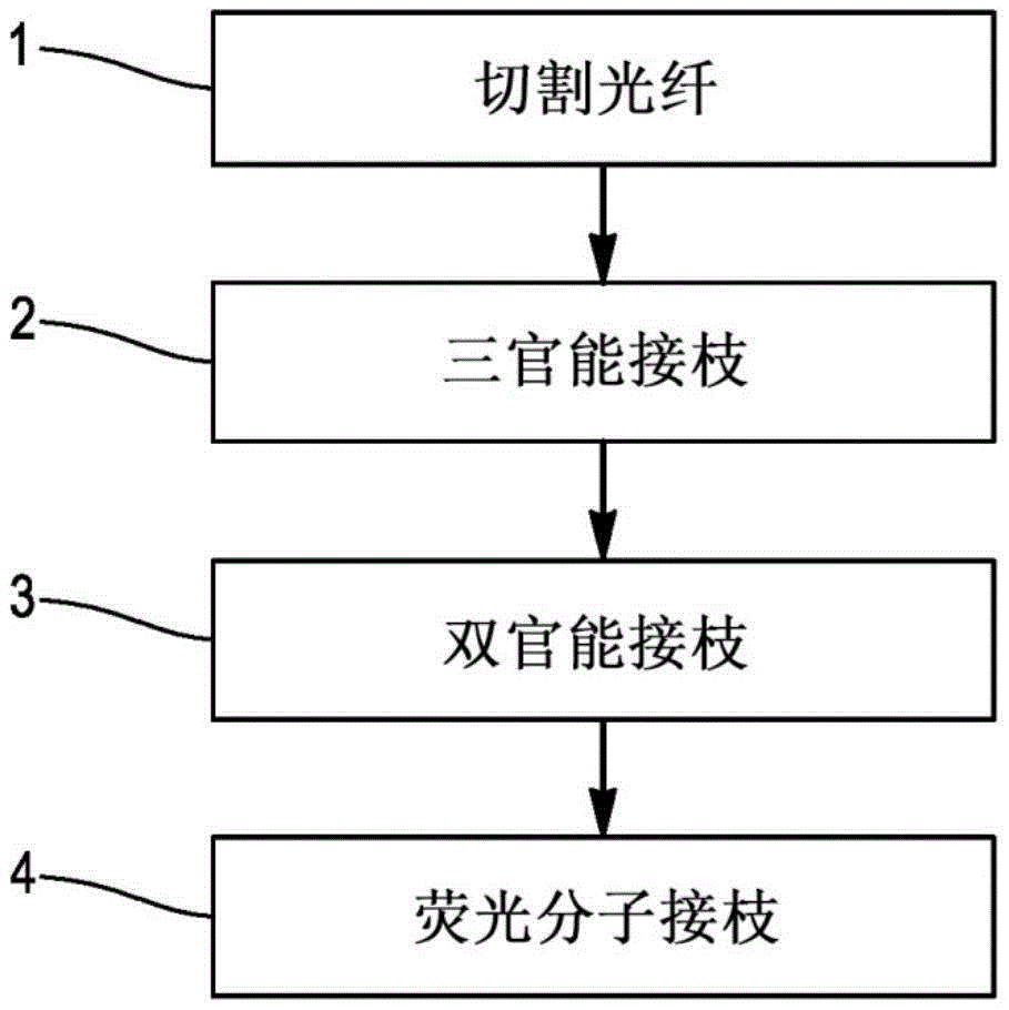
FIG. 1 is a flow chart showing the different steps of a method of functionalising an optical fibre according to the present invention;
FIG. 2 is a schematic diagram of a cross-sectional view of one end of an optical fiber after cleaving in accordance with the present invention;
FIG. 3 is a schematic diagram of a cross-sectional view of the end portion of the optical fiber of FIG. 2 on which trifunctional grafting has been performed;
FIG. 4 is a schematic diagram of a cross-sectional view of the end portion of the optical fiber of FIG. 3 on which bifunctional chain grafting has been performed;
FIG. 5 is a schematic view of the chemical process during the grafting of fluorescent molecules at the end of the optical fiber in FIG. 4;
fig. 6 is a schematic diagram of a system for optical measurement of pH according to the present invention.
It is well known that the embodiments to be described below are in no way limiting. If this choice of features is sufficient to confer technical advantages or to distinguish the invention from the prior art, it is specifically contemplated that the variants of the invention comprise only the choice of features described below, and not other features described. This choice includes at least one feature without structural details, preferably functional, or only a part of it (if only this part is sufficient to confer technical advantages or to distinguish the invention with respect to the state of the art).
Although the present invention is not limited thereto, a method of functionalizing an optical fiber according to the present invention, which uses a succinimide ester as a coupling agent coupled with an amino-silane surface, will now be described.
Typically, the trifunctional silanes and difunctional silanes are prepared upstream in solution and then used with a large number of optical fibers. For example, a polypropylene flask fixed in a glass bottle may be used. The flask was filled with a trifunctional silane solution. Advantageously, one of the polypropylene aids acts as a catalyst. Toluene can also be used as a solvent, and the pH reaches 2. Other solvents may also be used. The bottle and flask assembly was then placed in a freezer to interrupt the polymerization.
The other flask was filled with the bifunctional silane in a similar manner. This flask was fixed to another glass bottle. The assembly was placed in an oven at 60 degrees celsius for several hours. The time in the oven depends on the desired length of the silane chain and indeed on the desired NH2The number of groups. The bottle and flask assembly was then placed in a refrigerator to interrupt the polymerization.
Fig. 1 is a flow chart illustrating the different steps of a method of functionalising an optical fibre according to the present invention. The method comprises four steps: cutting, trifunctional grafting, bifunctional grafting and fluorescent molecular grafting. These various steps will be re-discussed below with reference to fig. 1-5.
In step 1, the end of the optical fiber is stripped and cleaved. After the pre-thawing of the trifunctional silane solution, the freshly cleaved end of the optical fiber is immersed in the trifunctional silane solution in step 2 of trifunctional grafting.
As shown in fig. 2, free hydroxyl OH ions are spontaneously present on the cleaved surface 5 of the optical fiber 6 and remain available for a period of time. For this purpose, step-index multimode fibers having an OH ion content of more than 10ppm are used. The ion content is high.
In the present case, the cleavage step 1 is separated from the grafting step 2 of the trifunctional silane in only a few minutes, so that within these minutes the least free hydroxyl OH functions are lost by binding with atmospheric contaminants. Activation by uv-ozone radiation or by using a piranha mixture or any other method is not required. Step 2 of grafting the trifunctional silane is carried out at room temperature for a few minutes. This is sufficient to completely form the trifunctional thin layer.
Advantageously, trifunctional and bifunctional grafting use silanes. The silane molecule consists of three parts. The first part formed by the silicon atom comprises 1, 2 or 3 bonds and the second part comprises a reactive group R which may be an alkoxy group, a halogen atom or a hydroxyl group. For example, the alkoxy group may include ethoxy-OCH2CH3methoxy-OCH3With reference to alkoxysilanes, the halogen atom may include chloro-Cl, with reference to chlorosilanes.
The third part is one or several of the remaining bonds between the silicon atom and the carbon atoms of the aliphatic chain, called spacer, formed by functional groups (-SH, -NH)2、COOH、-CH3OH, -OH, etc.), which determines the properties of the final product. The spacer can be of variable length and can even be omitted, for example in triethoxysilane.
The number of reactive groups R defines the number of Si-O-Si bonds which can be generated during the grafting reaction. The silica surface requires two bonds of this type to properly connect the silicon atoms. Thus, only a monolayer can be produced using a bifunctional silane (two functional groups). To increase the thickness of the graft layer, trifunctional silanes (three functional groups) are advantageously used to produce the first graft layer, so that additional functional groups are available.
In fig. 3, it can be seen that the aminosilane molecules have been bonded to the oxygen atoms of the OH groups, which are free immediately after cleavage. This arrangement theoretically requires the grafting thereon of the group R of the bifunctional amino-silane, for example NH2Amine groups and OH groups.
In step 3 of fig. 1, the optical fiber is then immersed in the bifunctional silane solution for several hours at room temperature. Also, it is not necessary to place the assembly in an oven. The fiber was then cleaned in toluene and DMSO (dimethyl sulfoxide). The latter is used to wash away everything that is not covalently grafted.
In fig. 4, the molecular chain of the linear polymer of bifunctional amino-silane is in contact with and bonded to the trifunctional layer by covalent bond. Short chains bind faster than long chains. Note that NH2Amine functionality is available. The layer is not formed on the sidewalls of the fibers. Since the trifunctional layer is present only at the end of the fiber, the bifunctional layer is formed mainly or only on the cut portion. The side wall of the optical fiber 6 in fig. 4 may optionally receive several silane chains, but the layer is formed on the cleaved surface at its end in the extension of the optical fiber.
In step 4 of FIG. 1, the fiber is immersed in a solution of fluorescent molecules in order to covalently graft enough fluorescent molecules to all available NH2On the amine function. This step 4 may take several hours or less, for example 6 hours. Finally, the fiber is optionally cleaned in water and then rinsed. Washing with DMSO (dimethyl sulfoxide) is also possible, which eliminates all molecules that are not covalently bound to the support.
Fig. 5 is a chemical equation showing the grafting of fluorescent molecules on the dual functional layer. For example, succinimide ester functionality is used as a coupling agent for coupling to aminated surfaces. The ester includes a fluorophore such as fluorescein diacetate. Binding to the aminated surface makes it possible to obtain a surface carrying the fluorophore via a CONH bond. Again, the formation of the layer occurs mainly at the cut surface, which enables to obtain active regions distributed along the bifunctional chains. This improves the efficiency of fluorescence detection.
Several fluorophores can be used. In the described example, the silane layer has available amine groups. Different coupling agents can be used between the fluorophore and the aminated surface, for example:
-a succinimide ester functional group as described above,
-a sulfonyl chloride,
-an isothiocyanate function,
-and so on.
It is also possible to have thiolated HS functions on which molecules reactive with thiols will be grafted, without amine functions. For example, it is possible to use the following compounds as coupling agents:
-an iodoacetamide (I) and (II) and (III),
-a maleimide group, wherein the maleimide group is a maleimide group,
-and so on.
These lists are non-limiting, and other molecules may be used: 7-hydroxycoumarin-3-carboxylic acid N-succinimidyl Ester (which can be grafted on the aminated surface) or pHrodo iFL Red STP Ester (which can be grafted on the aminated surface).
A system for optically measuring the pH of a solution using an optical fiber designed according to the method of the present invention will now be described with reference to fig. 6. It can be seen that the optical fiber 6 according to the invention has a diameter of, for example, 200 μm and comprises, at its free end, a functionalized layer 7 comprising fluorescent molecules sensitive to the pH of the solution 8 to be measured. The other end of the optical fiber 6 is connected to a beam splitter. The latter is connected to an excitation path 10 and a measurement path 11, the excitation path 11 being adapted to receive an excitation signal originating from a 488nm (not shown) laser. The measurement route is intended to transmit the fluorescence signal originating from the functionalized layer 7 to a spectrometer (not shown).
The molecules are excited directly by the light emitted by the optical fiber 6 at the selected wavelength. The fluorescence is collected by this same optical fiber and transmitted to the spectrometer through the beam splitter 9. The spectrometer is equipped with a dichroic prism 17 which filters the emission line in order to send only the fluorescence signal to the spectrometer. Also shown in the beam splitter 9 are collimator lenses 12-14, an excitation filter 15 for excitation signals with as clean an excitation as possible, and an emission filter 16 for passing the signals to the spectrometer. Between the excitation filter 15 and the dichroic prism 17 a mirror 18 is placed to direct the excitation light beam towards the dichroic prism.
The optical fiber 6 acts as a pH sensor, an excitation channel carrying at its end the excitation signal of the grafted fluorescent molecules and an emission channel of the light emitted by the carried fluorescent molecules.
The pH value can be estimated in different ways, for example by using a scheme of fluorescence spectrum shape, i.e. the total number of measurement points provided by the spectrometer.
This approach can be implemented, for example, when using fluorescein diacetate molecules, which are common cost-effective fluorophores that are stable and have high quantum efficiencies (0.93). As the surrounding pH increases, the fluorescein diacetate molecule is more or less deprotonated, forming four species (cationic, neutral, anionic and dianionic forms). To calculate the concentration of each species, three laws of mass action must be followed, expressed as different pKa's (2.2; 4.3 and 6.38). Only anionic and dianionic species are fluorescent. Others are converted to anionic form in a certain proportion and participate in fluorescence accordingly. The protocol may be referred to in the publications "Calibration free and fluorescent based fiber optical pH sensor for clinical applications", Bernard Gauthier-Manual et al, IEEE SENSOR, 10 months 28 to 31 days, New Delhi,2018, Proceedings IEEE Sensors, ISBN: 978-1-5386-.
In general, the principle is based solely on wavelength λ, pH and three apparent acidity constants pKa'1、pKa’2、pKa’3Etc. (function of the environment measured from the grafted molecules) to obtain the mathematical function Fluo (λ, pH, pKa ') representing the fluorescence spectrum of the grafted fluorescein'1、pKa’2、pKa’3). A simple adjustment of the spectrum measured with the function k × Fluo () will give the value of pH and pKa' measured by the sensor, the parameter k taking into account the concentration of fluorescent molecules at the end of the fiber.
Thus, the invention enables the measurement of pH in biological or physicochemical systems, but it can also be applied to the measurement of pH such as Ca++、Mg++Ions, and the like.
Of course, the invention is not limited to the examples just described, and many modifications can be made to these examples without departing from the scope of the invention.
Claims (16)
Applications Claiming Priority (3)
| Application Number | Priority Date | Filing Date | Title |
|---|---|---|---|
| FRFR1901263 | 2019-02-08 | ||
| FR1901263A FR3092666B1 (en) | 2019-02-08 | 2019-02-08 | A method of manufacturing an optical fiber-based pH measurement sensor. |
| PCT/EP2019/087180 WO2020160835A1 (en) | 2019-02-08 | 2019-12-30 | Method of manufacture of an optical fibre-based ph measurement sensor |
Publications (2)
| Publication Number | Publication Date |
|---|---|
| CN113424053A true CN113424053A (en) | 2021-09-21 |
| CN113424053B CN113424053B (en) | 2024-08-09 |
Family
ID=67107742
Family Applications (1)
| Application Number | Title | Priority Date | Filing Date |
|---|---|---|---|
| CN201980091484.6A Active CN113424053B (en) | 2019-02-08 | 2019-12-30 | Method for manufacturing pH measuring sensor based on optical fiber |
Country Status (5)
| Country | Link |
|---|---|
| US (1) | US11846589B2 (en) |
| EP (1) | EP3921628B1 (en) |
| CN (1) | CN113424053B (en) |
| FR (1) | FR3092666B1 (en) |
| WO (1) | WO2020160835A1 (en) |
Citations (7)
| Publication number | Priority date | Publication date | Assignee | Title |
|---|---|---|---|---|
| WO1988005533A1 (en) * | 1987-01-16 | 1988-07-28 | Kelsius, Inc. | Amplification of signals from optical fibers |
| US5028395A (en) * | 1989-07-20 | 1991-07-02 | Commissariat A L'energie Atomique | Active chemical sensor with optical fiber and its production process |
| US5277872A (en) * | 1990-10-16 | 1994-01-11 | Puritan-Bennett Corporation | Optical fiber pH microsensor and method of manufacture |
| US20050090014A1 (en) * | 2002-12-17 | 2005-04-28 | Govind Rao | Ratiometric fluorescent pH sensor for non-invasive monitoring |
| CN101881732A (en) * | 2010-06-02 | 2010-11-10 | 复旦大学附属中山医院 | Fluorescent fiber optic sensor capable of real-time monitoring of blood pH and preparation method thereof |
| CN204101452U (en) * | 2014-09-29 | 2015-01-14 | 中国计量学院 | Based on the Streptavidin concentration sensor of single-mode fiber |
| CN107789054A (en) * | 2017-11-13 | 2018-03-13 | 中国医学科学院生物医学工程研究所 | A kind of optical fiber for laser surgery activates devices and methods therefor |
Family Cites Families (2)
| Publication number | Priority date | Publication date | Assignee | Title |
|---|---|---|---|---|
| US5403746A (en) * | 1993-11-30 | 1995-04-04 | Minnesota Mining And Manufacturing Company | Sensor with improved drift stability |
| US5656241A (en) * | 1995-09-07 | 1997-08-12 | Optical Sensors Incorporated | Method for manufacturing fiber optic sensors |
-
2019
- 2019-02-08 FR FR1901263A patent/FR3092666B1/en not_active Expired - Fee Related
- 2019-12-30 EP EP19832418.8A patent/EP3921628B1/en active Active
- 2019-12-30 US US17/422,073 patent/US11846589B2/en active Active
- 2019-12-30 WO PCT/EP2019/087180 patent/WO2020160835A1/en not_active Ceased
- 2019-12-30 CN CN201980091484.6A patent/CN113424053B/en active Active
Patent Citations (7)
| Publication number | Priority date | Publication date | Assignee | Title |
|---|---|---|---|---|
| WO1988005533A1 (en) * | 1987-01-16 | 1988-07-28 | Kelsius, Inc. | Amplification of signals from optical fibers |
| US5028395A (en) * | 1989-07-20 | 1991-07-02 | Commissariat A L'energie Atomique | Active chemical sensor with optical fiber and its production process |
| US5277872A (en) * | 1990-10-16 | 1994-01-11 | Puritan-Bennett Corporation | Optical fiber pH microsensor and method of manufacture |
| US20050090014A1 (en) * | 2002-12-17 | 2005-04-28 | Govind Rao | Ratiometric fluorescent pH sensor for non-invasive monitoring |
| CN101881732A (en) * | 2010-06-02 | 2010-11-10 | 复旦大学附属中山医院 | Fluorescent fiber optic sensor capable of real-time monitoring of blood pH and preparation method thereof |
| CN204101452U (en) * | 2014-09-29 | 2015-01-14 | 中国计量学院 | Based on the Streptavidin concentration sensor of single-mode fiber |
| CN107789054A (en) * | 2017-11-13 | 2018-03-13 | 中国医学科学院生物医学工程研究所 | A kind of optical fiber for laser surgery activates devices and methods therefor |
Non-Patent Citations (2)
| Title |
|---|
| RUTJAPHAN KATEKLUM ET AL.: "Improving the sensitivity of amino-silanized sensors using self-structured silane layers: Application to fluorescence pH measurement", SENSORS AND ACTUATORS B: CHEMICAL, vol. 248, 10 April 2017 (2017-04-10), pages 605 - 612, XP029995102, DOI: 10.1016/j.snb.2017.04.049 * |
| 蒋姗 等: "共聚物Poly(DMAEMA-co-TPE-a)的合成 及pH 敏感荧光多孔光纤制备", 功能高分子学报, vol. 30, no. 1, 31 March 2017 (2017-03-31), pages 103 - 109 * |
Also Published As
| Publication number | Publication date |
|---|---|
| WO2020160835A1 (en) | 2020-08-13 |
| EP3921628A1 (en) | 2021-12-15 |
| US20220128478A1 (en) | 2022-04-28 |
| FR3092666B1 (en) | 2021-01-15 |
| US11846589B2 (en) | 2023-12-19 |
| EP3921628B1 (en) | 2022-11-23 |
| FR3092666A1 (en) | 2020-08-14 |
| CN113424053B (en) | 2024-08-09 |
| CA3128432A1 (en) | 2020-08-13 |
Similar Documents
| Publication | Publication Date | Title |
|---|---|---|
| Li et al. | Optical fiber optofluidic bio‐chemical sensors: a review | |
| Janczuk-Richter et al. | Long-period fiber grating sensor for detection of viruses | |
| De Vos et al. | Multiplexed antibody detection with an array of silicon-on-insulator microring resonators | |
| US6558958B1 (en) | Optical fiber evanescent field excited fluorosensor and method of manufacture | |
| US7796262B1 (en) | Integrated optical resonator device for measuring chemical and biological analyte concentrations | |
| Corres et al. | Tapered optical fiber biosensor for the detection of anti-gliadin antibodies | |
| Giovanardi et al. | Hollow core inhibited coupling fibers for biological optical sensing | |
| Mansor et al. | Taper biosensor in fiber ring laser cavity for protein detection | |
| Zhang et al. | Label-free detection of DNA hybridization utilizing dual S-tapered thin-core fiber interferometer | |
| CN119452254A (en) | Method for determining DNA concentration in DNA viruses | |
| Koba et al. | Reusable bacteriophage adhesin-coated long-period grating sensor for bacterial lipopolysaccharide recognition | |
| CN113424053B (en) | Method for manufacturing pH measuring sensor based on optical fiber | |
| JP2009287999A (en) | Fluorescence detecting system and concentration measuring method using it | |
| Wan et al. | Label-free, ultralow detection limit DNA biosensor employing tilted fiber bragg grating functionalized by 3-D nanostructure probes | |
| CA3128432C (en) | Method of manufacture of an optical fibre-based ph measurement sensor | |
| EP2960645A2 (en) | Reusable long period microfiber grating for detection of dna hybridization | |
| Udos et al. | Enhanced detectability of SARS-CoV-2 using sandwich immunoassay sensor based on tilted fiber Bragg grating with strong cladding mode resonances | |
| US20230081434A1 (en) | Sensor for detecting a target analyte in a liquid medium with an optical resonator coupled to a mechanical resonator | |
| Long et al. | Thin-core fiber-optic biosensor for DNA hybridization detection | |
| La Grasta et al. | Multiplexed Microphotonic Ring Resonator Platform for Simultaneous Detection of SARS-CoV-2 Spike Protein and Respiratory Syncytial Virus-F Protein | |
| PL243332B1 (en) | SARS-CoV-2 virus detection kit and method of functionalization of a measuring head | |
| Marrou et al. | Multiplexed, space distributed chemo/biosensors by means of time resolved, in-fiber acousto-optic interaction | |
| Hunt et al. | Bioconjugation of ultra-high-Q optical microcavities for label-free sensing | |
| CN222800606U (en) | Optical sensor for selectively detecting metal ions | |
| CN120077262A (en) | Calcium ion selective optical sensor and method for manufacturing same |
Legal Events
| Date | Code | Title | Description |
|---|---|---|---|
| PB01 | Publication | ||
| PB01 | Publication | ||
| SE01 | Entry into force of request for substantive examination | ||
| SE01 | Entry into force of request for substantive examination | ||
| GR01 | Patent grant | ||
| GR01 | Patent grant |