CN113423323A - Ophthalmic Devices - Google Patents
Ophthalmic Devices Download PDFInfo
- Publication number
- CN113423323A CN113423323A CN201980090331.XA CN201980090331A CN113423323A CN 113423323 A CN113423323 A CN 113423323A CN 201980090331 A CN201980090331 A CN 201980090331A CN 113423323 A CN113423323 A CN 113423323A
- Authority
- CN
- China
- Prior art keywords
- optical path
- anterior segment
- alignment
- imaging
- anterior
- Prior art date
- Legal status (The legal status is an assumption and is not a legal conclusion. Google has not performed a legal analysis and makes no representation as to the accuracy of the status listed.)
- Pending
Links
Images


Classifications
-
- A—HUMAN NECESSITIES
- A61—MEDICAL OR VETERINARY SCIENCE; HYGIENE
- A61B—DIAGNOSIS; SURGERY; IDENTIFICATION
- A61B3/00—Apparatus for testing the eyes; Instruments for examining the eyes
- A61B3/10—Objective types, i.e. instruments for examining the eyes independent of the patients' perceptions or reactions
- A61B3/101—Objective types, i.e. instruments for examining the eyes independent of the patients' perceptions or reactions for examining the tear film
-
- A—HUMAN NECESSITIES
- A61—MEDICAL OR VETERINARY SCIENCE; HYGIENE
- A61B—DIAGNOSIS; SURGERY; IDENTIFICATION
- A61B3/00—Apparatus for testing the eyes; Instruments for examining the eyes
- A61B3/0016—Operational features thereof
- A61B3/0025—Operational features thereof characterised by electronic signal processing, e.g. eye models
-
- A—HUMAN NECESSITIES
- A61—MEDICAL OR VETERINARY SCIENCE; HYGIENE
- A61B—DIAGNOSIS; SURGERY; IDENTIFICATION
- A61B3/00—Apparatus for testing the eyes; Instruments for examining the eyes
- A61B3/0016—Operational features thereof
- A61B3/0041—Operational features thereof characterised by display arrangements
-
- A—HUMAN NECESSITIES
- A61—MEDICAL OR VETERINARY SCIENCE; HYGIENE
- A61B—DIAGNOSIS; SURGERY; IDENTIFICATION
- A61B3/00—Apparatus for testing the eyes; Instruments for examining the eyes
- A61B3/10—Objective types, i.e. instruments for examining the eyes independent of the patients' perceptions or reactions
- A61B3/117—Objective types, i.e. instruments for examining the eyes independent of the patients' perceptions or reactions for examining the anterior chamber or the anterior chamber angle, e.g. gonioscopes
-
- A—HUMAN NECESSITIES
- A61—MEDICAL OR VETERINARY SCIENCE; HYGIENE
- A61B—DIAGNOSIS; SURGERY; IDENTIFICATION
- A61B3/00—Apparatus for testing the eyes; Instruments for examining the eyes
- A61B3/10—Objective types, i.e. instruments for examining the eyes independent of the patients' perceptions or reactions
- A61B3/14—Arrangements specially adapted for eye photography
-
- A—HUMAN NECESSITIES
- A61—MEDICAL OR VETERINARY SCIENCE; HYGIENE
- A61B—DIAGNOSIS; SURGERY; IDENTIFICATION
- A61B5/00—Measuring for diagnostic purposes; Identification of persons
- A61B5/0059—Measuring for diagnostic purposes; Identification of persons using light, e.g. diagnosis by transillumination, diascopy, fluorescence
- A61B5/0071—Measuring for diagnostic purposes; Identification of persons using light, e.g. diagnosis by transillumination, diascopy, fluorescence by measuring fluorescence emission
Landscapes
- Health & Medical Sciences (AREA)
- Life Sciences & Earth Sciences (AREA)
- Engineering & Computer Science (AREA)
- Surgery (AREA)
- General Health & Medical Sciences (AREA)
- Biophysics (AREA)
- Biomedical Technology (AREA)
- Heart & Thoracic Surgery (AREA)
- Medical Informatics (AREA)
- Molecular Biology (AREA)
- Physics & Mathematics (AREA)
- Animal Behavior & Ethology (AREA)
- Veterinary Medicine (AREA)
- Public Health (AREA)
- Ophthalmology & Optometry (AREA)
- Pathology (AREA)
- Signal Processing (AREA)
- Eye Examination Apparatus (AREA)
- Microscoopes, Condenser (AREA)
- Lenses (AREA)
Abstract
Several exemplary embodiments of ophthalmic devices include an illumination system, an imaging system, an anterior ocular imaging system, a first optical path coupling element, and a control section. The illumination system projects illumination light output from the light source to an anterior ocular segment of the eye to be examined. The interference imaging system has a structure for imaging an interference pattern formed on a cornea by illumination light. The anterior segment imaging system has a configuration for imaging an anterior segment on which illumination light is projected. The first optical path coupling element couples an optical path of the imaging system with an optical path of the anterior ocular segment imaging system. The control unit displays an interference image acquired by the interference imaging system and an anterior segment image acquired by the anterior segment imaging system on the display device in a superimposed manner.
Description
Technical Field
The present invention relates to an ophthalmic device for examining the tear condition of an eye to be examined.
Background
In recent years, patients with dry eye have increased. This is considered to be due to overuse of eyes by a work (VDT (video display terminal) work) performed using a display of a computer or the like, air drying by an air-conditioned room, wearing contact lenses, and the like.
The most common method for dry eye examination is the Schirmer Test (Schirmer Test), which measures the amount of tear fluid. In addition, examination (tear layer destruction time (BUT) examination) was also performed to observe the cornea stained with fluorescein using a slit lamp microscope and to measure the stability of tear fluid.
The following devices are known as devices for performing examination of dry eye. Patent document 1 discloses an ophthalmologic apparatus in which, in order to efficiently obtain specular reflection light at the anterior segment of an eye to be examined, a light projection system is arranged such that light is incident substantially perpendicularly on a corneal surface, and a stop having substantially the same size as the exit pupil of the specular reflection light is arranged in the vicinity of the exit pupil.
Patent document 2 discloses an ophthalmologic apparatus that obtains a time-series change in hue of an interference pattern (interference pattern) formed by a tear layer from a time-series image obtained by color-imaging the interference pattern in order to objectively examine the state of the tear layer.
Patent document 3 discloses an ophthalmologic apparatus that analyzes an interference pattern for each color component of an image obtained by color-capturing an interference pattern formed by a tear layer to accurately quantify the state of development of dry eye, and evaluates the state of development of dry eye.
Patent document 4 discloses an ophthalmologic apparatus that, in order to objectively evaluate the type of dry eye, evaluates the position and shape of a dry spot and the movement direction of tear liquid around the dry spot by processing a plurality of front images obtained by continuously imaging the anterior segment of an eye to be examined.
Patent document 1: japanese laid-open patent publication No. 9-289970
Patent document 2: japanese patent laid-open publication No. 2001-309889
Patent document 3: japanese patent laid-open publication No. 2005-211173
Patent document 4: japanese patent laid-open publication No. 2017-136212
Disclosure of Invention
As disclosed in patent document 4, one of the important items for evaluating dry eye syndrome is the location of dry spots (more generally, distribution of tear thickness or distribution of tear state abnormality). Of course, before the examination, it is not known that an abnormality has occurred at that position of the anterior ocular segment. Therefore, in order to not miss an abnormality occurring at the end of the cornea, and to perform an inspection efficiently, it is desirable to be able to observe a wide range of the anterior segment.
In addition, when presenting the inspection result, it is desirable to display the position and distribution of the abnormality so as to be superimposed on the anterior segment image, so that the abnormality occurrence position of the anterior segment can be easily (intuitively) grasped. The anterior segment image is desirably a wide-range image depicting the anterior segment.
Further, in consideration of the possibility of displacement between the interference pattern image and the anterior segment image due to eye movement or body movement, it is desirable to substantially simultaneously perform imaging of the interference pattern for obtaining the abnormal position and distribution and imaging of the anterior segment for obtaining the anterior segment image.
In the prior art, it has been difficult to satisfy these requirements relating to ophthalmic devices used for examining dry eye.
The purpose of the present invention is to provide a lacrimal fluid abnormality occurrence position that can be presented with good positional accuracy over a wide range of the anterior segment.
An ophthalmic apparatus of a first of several illustrative embodiments includes an illumination system, an imaging system, an anterior ocular imaging system, a first optical path coupling element, and a control section. The illumination system projects illumination light output from the light source to an anterior ocular segment of the eye to be examined. The interference imaging system has a structure for imaging an interference pattern formed on a cornea by illumination light. The anterior segment imaging system has a configuration for imaging an anterior segment on which illumination light is projected. The first optical path coupling element couples an optical path of the imaging system with an optical path of the anterior ocular segment imaging system. The control unit displays an interference image acquired by the interference imaging system and an anterior segment image acquired by the anterior segment imaging system on the display device in a superimposed manner.
In a second aspect of several exemplary embodiments, the ophthalmic device according to the first aspect, further comprises: a first lens group disposed on the eye side with respect to the first optical path coupling element; and a second lens group disposed on the opposite side of the eye to be inspected with respect to the first optical path coupling element. The first lens group and the second lens group function as object lenses of an imaging system. The first lens group functions as an objective lens of the anterior ocular segment imaging system.
In a third aspect of some exemplary embodiments, according to the ophthalmic apparatus of the second aspect, a lens closest to the first optical path coupling element among lenses included in the anterior ocular segment photographing system is disposed at or near a focal position of the first lens group.
A fourth aspect of several exemplary embodiments is the ophthalmic device of any one of the first to third aspects, further comprising a second optical path coupling element for coupling an optical path of the illumination system and an optical path of the imaging system.
In a fifth aspect of several exemplary embodiments, the ophthalmic device of the fourth aspect, the first and second optical path coupling elements are beam splitters, respectively. Return light of illumination light for imaging an interference pattern is reflected by the first optical path coupling element and the second optical path coupling element, respectively, and is guided to an imaging element of the imaging system.
A sixth mode of several exemplary embodiments is the ophthalmic apparatus according to any one of the first to fifth modes, further comprising an illumination intensity changing section that changes an intensity of the illumination light projected toward the anterior eye.
A seventh mode of several exemplary embodiments, the ophthalmic device according to any one of the first to sixth modes, further comprising an excitation filter and a blocking filter. The excitation filter generates excitation light from the illumination light that is directed to the fluorescent agent of the anterior eye. The blocking filter selectively passes fluorescence emitted by the fluorescent agent subjected to the excitation light.
An eighth of several exemplary embodiments is the ophthalmic device of any of the first to seventh aspects, further comprising a projection system, a detection system, and a first alignment section. The projection system projects the alignment light toward the front eye in a direction inclined with respect to an optical axis of an optical path from the first optical path coupling element toward the eye to be inspected. The detection system detects reflected light of the alignment light at the anterior eye portion. The first alignment section performs alignment in a direction along the optical axis based on an output from the detection system.
Ninth of several exemplary embodiments, the ophthalmic apparatus according to the eighth aspect, the projection system comprises an alignment light source that outputs alignment light, and the detection system comprises an image sensor that detects reflected light of the alignment light at the anterior eye. The alignment light source and the image sensor are disposed on the opposite side of the eye to be inspected with respect to the first optical path coupling element.
A tenth of the several exemplary embodiments, the ophthalmic device of any of the first to ninth aspects, further comprising a second alignment portion. The second alignment section performs alignment in a direction orthogonal to the optical axis of the optical path from the first optical path coupling element toward the eye to be inspected, based on the anterior segment image acquired by the anterior segment photographing system.
An eleventh aspect of several exemplary embodiments provides the ophthalmic apparatus according to any one of the first to seventh aspects, comprising two or more photographing sections and a third alignment section. The two or more imaging units image the anterior segment of the eye from different directions. The third alignment unit performs three-dimensional alignment based on two or more captured images acquired by the two or more imaging units, respectively.
According to the embodiment, the abnormality occurrence position of the tear state can be presented with good positional accuracy over a wide range of the anterior segment.
Drawings
Fig. 1 is a schematic diagram showing an example of the structure of an ophthalmic apparatus according to an exemplary embodiment.
Fig. 2 is a schematic diagram showing an example of the structure of an ophthalmic apparatus of an exemplary embodiment.
Fig. 3 is a schematic diagram for explaining an example of the structure of an ophthalmic apparatus according to an exemplary embodiment.
Fig. 4 is a flowchart showing an example of the operation of the ophthalmic apparatus according to the exemplary embodiment.
Fig. 5A is a schematic diagram showing an example of the configuration of an ophthalmic apparatus according to a modification.
Fig. 5B is a schematic diagram showing an example of the configuration of an ophthalmic apparatus according to a modification.
Fig. 6 is a schematic diagram showing an example of the configuration of an ophthalmic apparatus according to a modification.
Detailed Description
Several exemplary embodiments of ophthalmic devices are described in detail with reference to the accompanying drawings.
First, an outline of the embodiment will be described. The ophthalmologic apparatus according to the embodiment is configured to capture an interference pattern representing a state of tears on a cornea to acquire an interference image, capture an anterior eye image, and display the interference image and the anterior eye image in a superimposed manner. At least a portion of the set of components used for imaging (the imaging system) is different from the set of components used for anterior segment imaging (the anterior segment imaging system).
The interference image to be presented may be the interference image itself (original image) acquired by the imaging system, or may be an interference image (processed image) obtained by processing the original image. The processed image may be, for example, a color map in which a parameter distribution represented by the original image is represented in a pseudo color, or a map in which a region in which a parameter value falls within a predetermined range is represented. The parameter may be, for example, the thickness of any one layer, two layers, or three layers of an oil layer, a water layer, and a mucin layer constituting the tear fluid. The processed image is an image obtained by applying arbitrary image processing such as correction, adjustment, and enhancement to the original image.
Similarly, the presented anterior segment image may be the anterior segment image itself (original image) acquired by the anterior segment imaging system, or may be an anterior segment image (processed image) obtained by processing the original image. The processed image may be an image obtained by applying arbitrary image processing such as correction, adjustment, and enhancement to the original image, for example.
The ophthalmic apparatus according to the embodiment may include or may not include a display device that displays the interference image and the anterior segment image. In the latter case, the display device is a peripheral of the ophthalmic device of the embodiment.
In this specification, unless otherwise specifically mentioned, "image data" and "image" based on the image data are not distinguished. Likewise, unless otherwise mentioned, a part or tissue of the eye to be inspected and an image representing the part or tissue of the eye to be inspected are not distinguished.
In the present specification, unless otherwise specified, "lens" means a single lens or a combination of two or more lenses. Likewise, a "lens group" means a set of two or more lenses or a single lens, unless otherwise mentioned.
In addition, in the present specification, the term "processor" refers to, for example, a Circuit such as a CPU (Central Processing Unit), a GPU (Graphics Processing Unit), an ASIC (Application Specific Integrated Circuit), a Programmable Logic Device (e.g., SPLD (Simple Programmable Logic Device), a CPLD (Complex Programmable Logic Device), and an FPGA (Field Programmable Gate Array)). The processor can realize the functions of the embodiments by, for example, reading and executing a program stored in a memory circuit or a storage device.
Structure
Fig. 1 and 2 show a configuration example of an ophthalmic apparatus according to an embodiment. The ophthalmologic apparatus 1 has a function of capturing an interference pattern indicating a tear state on the cornea Ec of the eye E to be inspected, a function of capturing the anterior segment Ea, and a function of presenting the interference pattern by superimposing the interference image on the anterior segment image.
As an exemplary configuration for realizing these functions, the ophthalmologic apparatus 1 includes an inspection unit 2, a unit moving mechanism 70, a display device 80, an operation device 90, and a computer 100. The computer 100 may be, for example, an embedded system (embedded system) of the ophthalmic apparatus 1.
The inspection unit 2 houses various optical systems and various mechanisms. The exemplary examination unit 2 includes an illumination system 10, an interference photographing system 20, an anterior ocular photographing system 30, a first lens group including two lenses 41, 42, a second lens group including two lenses 43, 44, an optical path coupling element 51, a mirror 52, an optical path coupling element 53, an alignment light source 61, and an image sensor 62.
The illumination system 10 is configured to project illumination light to the anterior segment Ea of the eye E. The illustrative illumination system 10 includes an illumination source 11, a collimating lens 12, an excitation filter 13, and a tunable filter 14. The optical path of the illumination system 10 is formed by the illumination light source 11, the collimator lens 12, the excitation filter 13, the tunable filter 14, the (optical path coupling element 53), the mirror 52, the lens 44, the lens 43, the optical path coupling element 51, the lens 42, and the lens 41.
The illumination light source 11 outputs illumination light. The operation of the illumination light source 11 is controlled by the computer 100.
The collimator lens 12 converts the illumination light output from the illumination light source 11 into a parallel light beam. The collimator lens 12 is composed of, for example, a single lens or a combination of two or more lenses.
The excitation filter 13 is disposed in the optical path (in a state shown by a solid line) when the anterior ocular segment imaging mode is the fluoroscopic imaging mode, and is disposed outside the optical path (in a state shown by a broken line) in other cases. The excitation filter 13 is moved by an excitation filter moving mechanism 13A. The excitation filter moving mechanism 13A includes an actuator that operates in accordance with a command from the computer 100. The actuator may be, for example, a solenoid actuator.
In the fluorography, a fluorescent agent (fluorochrome) is administered to the anterior eye Ea. The excitation filter 13 generates excitation light of the fluorescent agent from the illumination light. That is, excitation filter 13 selectively passes wavelengths that excite the fluorescent agent. In a typical example, the fluorescent dye is fluorescein, and the passing center wavelength of the excitation filter 13 is set to be 494nm or near (for example, in the range of 490 to 500 nm) the absorption maximum wavelength of the fluorescein.
The tunable filter 14 is an optical element for changing the intensity (light quantity) of the illumination light projected to the eye E. Since it takes a certain time (10 seconds or more) to evaluate the time-series change of the interference pattern due to the tear fluid, it is considered desirable to adjust the intensity of the illumination light so that the eye of the subject is open. Tunable filter 14 is an example of a means for achieving this desire.
The tunable filter 14 may include, for example, either or both of a neutral filter (ND filter) and a band-pass filter (BPF). Tunable filter 14 may comprise a single filter or more than two filters.
In the case where the tunable filter 14 is formed of a single filter, the tunable filter 14 is, for example, an optical filter whose filter characteristics (e.g., pass characteristics, absorption characteristics) can be changed continuously or discretely. The control for changing the filter characteristic is performed by the computer 100.
In the case where the tunable filter 14 includes two or more filters, these filters are selectively arranged on the optical path. As a typical example of this case, the tunable filter 14 includes two or more filters mounted to the turret and an actuator that moves (typically rotates) the turret. The actuator may be, for example, a pulse motor that operates in accordance with a command (pulse control signal) from the computer 100.
Further, the intensity of the illumination light projected to the eye E can be changed without using the tunable filter 14. For example, some exemplary embodiments are configured to change the intensity of the illumination light projected to the eye E by changing either or both of the intensity and wavelength band of the illumination light output from the illumination light source 11. In some exemplary embodiments, the intensity of the illumination light projected to the eye E may be changed by a combination of the control of the illumination light source and the control of the tunable filter.
Any one of the two or more filters provided in the tunable filter 14 may be the excitation filter 13. When the tunable filter 14 includes the excitation filter 13, the computer 100 controls the tunable filter 14 to insert and retract the excitation filter 13 into and from the optical path during the fluoroscopic imaging.
According to the illumination system 10 of the present example, illumination light output from the illumination light source 11 is converted into parallel light fluxes by the collimator lens 12. When the fluorescence contrast imaging is applied, the illumination light having passed through the collimator lens 12 is converted into excitation light by the excitation filter 13, and the intensity of the excitation light is adjusted by the tunable filter 14. In the case where the fluoroscopic imaging is not applicable, the intensity of the illumination light passed through the collimator lens 12 is adjusted by the tunable filter 14. The illumination light (excitation light) having passed through the tunable filter 14 is projected to the anterior segment Ea via the optical path coupling element 53, the mirror 52, the lens 44, the lens 43, the optical path coupling element 51, the lens 42, and the lens 41.
The interference imaging system 20 is configured to image an interference pattern formed on the cornea by the illumination light projected to the anterior ocular segment Ea by the illumination system 10. The illumination light is reflected by the tear layer (layer boundary), thereby forming the interference pattern. For example, reflection light from the surface of an oil layer of tears and reflection light from the back face interfere with each other to form stripes corresponding to the thickness distribution of the oil layer.
The coherent imaging system 20 includes an aperture 21, a telecentric lens 22, and a coherent imaging camera 23. The optical path of the optical system 20 is formed by lens 41, lens 42, optical path coupling element 51, lens 43, lens 44, mirror 52, optical path coupling element 53, aperture 21, telecentric lens 22, and the camera 23.
The aperture 21 is an optical element for limiting (adjusting) the amount of light guided to the imaging camera 23. The aperture 21 may be a variable aperture controlled by the computer 100.
The telecentric lens 22 is, for example, an image-side telecentric (image-telecentric) lens. Accordingly, since the light rays are incident substantially perpendicularly on the entire imaging surface of the imaging camera 23, attenuation and halo can be eliminated, and the peripheral light amount ratio can be made uniform. The telecentric lens 22 is composed of, for example, a single lens or a combination of two or more lenses.
The imaging camera 23 generates an image (interference image) indicating an interference pattern formed on the cornea by detecting light passing through the telecentric lens 22. The imaging camera 23 has sensitivity at least in a visible range. The imaging camera 23 may be, for example, a color camera, typically a 3CCD (charge coupled device) camera or a 3CMOS (complementary metal oxide semiconductor) camera. This makes it possible to obtain interference images of various color components.
The reflected light of the illumination light projected to the anterior ocular segment Ea by the illumination system 10 is guided to the imaging camera 23 via the lens 41, the lens 42, the optical path coupling element 51, the lens 43, the lens 44, the mirror 52, the optical path coupling element 53, the aperture 21, and the telecentric lens 22.
The anterior segment imaging system 30 is configured to image the anterior segment Ea on which the illumination light is projected by the illumination system 10. The anterior segment photographing system 30 includes a blocking filter 31, a lens 32, and an anterior segment photographing camera 33. The optical path of the anterior segment photographing system 30 is formed by the lens 41, the lens 42, the (optical path coupling element 51), the blocking filter 31, the lens 32, and the anterior segment photographing camera 33.
When the program for anterior ocular segment imaging is fluorescence contrast imaging, the blocking filter 31 is disposed in the optical path (in the state shown by the solid line), and otherwise, the blocking filter 31 is disposed outside the optical path (in the state shown by the broken line). The movement of the barrier filter 31 is performed by the barrier filter moving mechanism 31A. The blocking filter moving mechanism 31A includes an actuator that operates in accordance with a command from the computer 100. The actuator may be, for example, a solenoid actuator.
The computer 100 synchronously controls the operation of the excitation filter moving mechanism 13A and the operation of the blocking filter moving mechanism 31A. That is, when the program for anterior ocular segment imaging is fluoroscopic imaging, the computer 100 controls the excitation filter moving mechanism 13A and the blocking filter moving mechanism 31A so that both the excitation filter 13 and the blocking filter 31 are disposed on the optical path, and when the program for anterior ocular segment imaging is not fluoroscopic imaging, the computer 100 controls the excitation filter moving mechanism 13A and the blocking filter moving mechanism 31A so that both the excitation filter 13 and the blocking filter 31 are disposed outside the optical path.
In the fluoroscopic imaging, a fluorescent agent (fluorochrome) applied to the anterior ocular segment Ea receives the excitation light generated by the excitation filter 13 and emits fluorescence of a specific wavelength. The blocking filter 31 selectively passes the wavelength of the fluorescence. As a typical example, in the case where the fluorescent dye is fluorescein, the passing center wavelength of the blocking filter 31 is set to be at or near the maximum emission wavelength 521nm of fluorescein.
The lens 32 is, for example, an imaging lens that images light on a light receiving surface of the anterior ocular segment photographing camera 33. Alternatively, the lens 32 may be a (image side) telecentric lens, as in the case of the imaging system 20. The lens 32 is composed of, for example, a single lens or a combination of two or more lenses.
Of the lenses 32, the lens located closest to the optical path coupling element 51 is disposed at or near the focal position of the first lens group composed of the two lenses 41 and 42. In the case where the lens 32 is formed of a single lens, the lens 32 is disposed at or near the rear focal position of the first lens group. In the case where the lens 32 is composed of two or more lenses, the lens located closest to the optical path coupling element 51, that is, the lens located closest to the eye to be inspected E, among these lenses is disposed at or near the rear focal position of the first lens group. This can enlarge the imaging field of view of the anterior segment imaging camera 33, and can image a wide range of the anterior segment Ea.
The anterior segment photographing camera 33 detects light passing through the lens 32, thereby photographing the anterior segment Ea. Thereby obtaining an anterior segment image. The anterior segment photographing camera 33 has sensitivity at least in a wavelength band for fluoroscopic photographing. The anterior ocular segment photographing camera 33 has sensitivity in, for example, a visible region and an infrared region. The anterior segment photographing camera 33 may be, for example, a color camera or a black-and-white camera, typically a CCD camera, a 3CCD camera, a CMOS camera, or a 3CMOS camera.
The first lens group including the two lenses 41 and 42 is disposed on the eye E side of the optical path coupling element 51. The second lens group including the two lenses 43 and 44 is disposed on the opposite side of the eye E from the optical path coupling element 51. In other words, the second lens group is disposed on the side of the imaging camera 23 with respect to the optical path coupling element 51.
The lens 41 has, for example, a concave or planar surface (front surface) on the eye E side, and a convex aspheric surface on the opposite side (rear surface) of the eye E. The lens 42 is formed in a convex or planar shape, for example, on both the front and rear surfaces.
The lens 43 and the lens 44 form a laminated lens. The lens 43 is formed in a convex shape on both front and rear surfaces, for example. The lens 44 is formed in a concave shape on, for example, both the front surface and the rear surface.
Such a lens structure is a structure for constituting two conditions that satisfy: (1) illumination light is substantially perpendicularly incident on each position of the cornea Ec; (2) the reflected light from each position of the cornea Ec travels in the opposite direction on a path substantially identical to the path of the illumination light incident on the position, reaches the lens 41, and is detected by the interference imaging system 20.
As can be seen from the light ray diagram (phantom) of fig. 3, the imaging system 20 of the present example satisfies these two conditions. Although patent document 1 describes the two conditions, a specific optical system that actually satisfies the two conditions is not disclosed in the publicly known document, and is considered to be the first one the inventors have studied.
By applying an optical system satisfying the above two conditions, the path of the illumination light corresponding to each position of the cornea Ec and the path of the reflected light thereof substantially coincide with each other, and as a result, the tear state distribution on the curved cornea Ec can be accurately captured from the direction perpendicular to the curved surface.
The structure for satisfying the above two conditions is not limited thereto. As a result of intensive studies, the inventors have confirmed that at least the optical system configurations (a) to (C) shown below satisfy the above two conditions. These are merely examples, and any modifications (omission, replacement, addition, and the like) are allowable.
(A) The optical system structure of this example uses three lenses as follows instead of the four lenses 41 to 44 of fig. 1. The front surface of the first lens closest to the eye to be inspected is formed in a concave shape, and the rear surface is formed in a convex aspherical shape. The front surface and the rear surface of the second lens adjacent to the first lens are both formed in a convex shape. The front surface of the third lens, the front surface of which is laminated on the rear surface of the second lens, is formed in a concave shape, and the rear surface is formed in a convex shape.
(B) The optical system structure of this example uses four lenses as follows instead of the four lenses 41 to 44 of fig. 1. The front surface of the first lens closest to the eye to be examined is formed in a gently convex shape or a planar shape, and the rear surface is formed in a convex aspherical shape. Both front and rear surfaces of the second lens, which is next to the eye to be inspected than the first lens, are formed in a convex shape. The front surface of the third lens, the front surface of which is laminated on the rear surface of the second lens, is formed in a concave shape, and the rear surface is formed in a convex shape. The front surface of the fourth lens, whose front surface is opposed to the rear surface of the third lens, is formed in a convex shape, and the rear surface is formed in a concave shape.
(C) The optical system structure of this example uses five lenses as follows instead of the four lenses 41 to 44 of fig. 1. The front surface of the first lens closest to the eye to be examined is formed in a planar or concave shape, and the rear surface is formed in a convex aspherical shape. The front surface of the second lens adjacent to the first lens is formed in a planar shape, and the rear surface is formed in a convex shape. The front surface and the rear surface of the third lens adjacent to the second lens are both formed in a convex shape. The front surface of the fourth lens, the front surface of which is laminated on the rear surface of the third lens, is formed in a concave shape, and the rear surface is formed in a convex shape. The front surface of a fifth lens adjacent to the fourth lens is formed in a convex shape, and the rear surface is formed in a concave shape.
In the example shown in fig. 1, the four lenses 41, 42, 43, and 44, that is, the first lens group and the second lens group, function as object lenses of the imaging system 20. In addition, the two lenses 41 and 42, that is, the first lens group function as an objective lens of the anterior ocular segment photographing system 30.
Accordingly, the imaging system 20 can cause illumination light to enter each position of the cornea Ec substantially perpendicularly, and can guide reflected light from each position of the cornea Ec to a path substantially identical to the incident path. On the other hand, the anterior segment imaging system 30 can secure a large imaging field of view, that is, can image a wide range of the anterior segment Ea.
Note that the light detected by the imaging system 20 and the light detected by the anterior ocular segment imaging system 30 are both return light from the anterior ocular segment Ea, but are different light from each other. As can be understood by those skilled in the art, it is not easy to configure the optical systems so as to detect such mutually different lights by separate optical systems configured to satisfy mutually different requirements, respectively.
The optical path coupling element 51 is an optical element that couples the optical path of the imaging system 20 with the optical path of the anterior ocular segment imaging system 30. The optical path coupling element 51 coaxially couples the optical path of the imaging system 20 and the optical path of the anterior ocular segment imaging system 30 (that is, couples the optical axes so as to intersect with each other), for example.
The optical path coupling element 51 may be any beam splitter. In this example, since the coherent imaging system 20 uses visible light having a wide bandwidth and the anterior segment imaging system 30 uses visible fluorescence (fluorescein), a half-lens can be used as the optical path coupling element 51. In the example shown in fig. 1, the optical path coupling element 51 also has a function of coupling the optical path of the illumination system 10 and the optical path of the anterior segment imaging system 30.
In some exemplary embodiments, when a structure for wavelength-separating the transmitted light (transmitted light) and the reflected light is adopted, a dichroic mirror can be used as the optical path coupling element 51. In other exemplary embodiments, when a structure for separating the transmitted light (transmitted light) and the reflected light by polarization is adopted, a polarization beam splitter can be used as the optical path coupling element 51. These are merely examples of means (first optical path coupling elements) for coupling the optical path of the imaging system and the optical path of the anterior ocular segment imaging system, and any modifications (omission, replacement, addition, and the like) are allowable.
The mirror 52 bends the optical path of the illumination system 10 and the optical path of the interference imaging system 20. This makes it possible to make the optical system compact, and as a result, to make the ophthalmic apparatus 1 compact. Further, the member usable for this purpose or other purposes is arbitrary, and the structure to be additionally adopted is also arbitrary. For example, the position, arrangement angle, number, size, and the like of the reflecting mirror can be appropriately designed. In addition, a member different from the mirror may be used.
The optical path coupling element 53 is provided with an optical element that couples the optical path of the illumination system 10 and the optical path of the imaging system 20. The optical path coupling element 53 coaxially couples, for example, an optical path of the illumination system 10 and an optical path of the imaging system 20.
The optical path coupling element 53 may be any beam splitter. In this example, since both the illumination system 10 and the imaging system 20 use wide-bandwidth visible light, a half-lens can be used as the optical path coupling element 53. As in the case of the optical path coupling element 51, a dichroic mirror, a polarization beam splitter, or another beam splitter can be used instead of the semi-transparent mirror as necessary.
In the example shown in fig. 1, light guided by the imaging system 20 (that is, return light of illumination light for imaging an interference pattern caused by tear fluid on the cornea Ec) passes through the two beam splitters but is reflected by both. That is, light guided by the imaging system 20 is reflected by the optical path coupling element 51 and is also reflected by the optical path coupling element 53 and guided to the imaging camera 23.
This structure is intended to avoid interference of light when passing through the beam splitter. Thereby, the interference pattern generated on the cornea Ec can be detected with high accuracy.
The alignment light source 61 and the image sensor 62 are used for alignment (Z-alignment) in a direction (Z-direction) along the optical axis of the lens 41. The alignment light source 61 projects light (for example, infrared light) for performing Z alignment to the eye E to be inspected. The light output from the alignment light source 61 is projected from an oblique direction to the cornea Ec by the lens 42 and the lens 41. The cornea reflection light of this light is imaged on the light receiving surface of the image sensor 62 by the lenses 41 and 42 (and other lenses not shown).
The image sensor 62 may be any one-or two-dimensional image sensor. That is, the image sensor 62 provided in the Z-alignment system may be any image sensor in which a plurality of light detection elements (photodiodes and the like) are arranged one-dimensionally or two-dimensionally. The image sensor 62 is typically a line sensor.
In several exemplary embodiments, light directed toward lens 42 from aiming light source 61 reaches lens 42, for example, through a notch, opening, or light-transmitting portion formed on optical path coupling element 51. Similarly, light directed from the lens 42 toward the image sensor 62 reaches the lens 42 through, for example, a notch, an opening, or a light-transmitting portion formed in the optical path coupling element 51. This allows the imaging field of view of the anterior segment imaging system 30 to be enlarged and a means for alignment to be provided while satisfying the above-described conditions regarding the imaging system 20.
When the position of the cornea Ec (corneal apex) changes in the Z direction, the projection position of light onto the light receiving surface of the image sensor 62 changes. The computer 100 can determine the position of the cornea Ec (corneal vertex) based on the position of the light detected by the image sensor 62. Then, the computer 100 controls the unit moving mechanism 70 based on the obtained cornea Ec (corneal vertex) to perform Z alignment of the inspection unit 2. This Z alignment method is an example of an alignment method using an optical lever.
The unit moving mechanism 70 three-dimensionally moves the inspection unit 2. In a typical example, the unit moving mechanism 70 includes a Z table that is movable in a Z direction (front-rear direction), a Z moving mechanism that moves the Z table, an X table that is movable in an X direction (left-right direction) orthogonal to the Z direction, an X moving mechanism that moves the X table, a Y table that is movable in a Y direction (up-down direction) orthogonal to both the Z direction and the X direction, and a Y moving mechanism that moves the Y table. Each of these moving mechanisms includes an actuator (e.g., a pulse motor) that operates under the control of the computer 100.
The display device 80 functions as a part of the user interface section, and displays information under the control of the computer 100. The display device 80 may be, for example, a Liquid Crystal Display (LCD) or an Organic Light Emitting Diode (OLED) display.
The operation device 90 functions as a part of the user interface section and is used for operating the ophthalmologic apparatus 1. The operating device 90 may include various hardware keys (levers, buttons, switches, etc.) provided to the ophthalmic apparatus 1. In addition, the operating device 90 may include various peripheral devices (a keyboard, a mouse, a joystick, an operation panel, and the like) connected to the ophthalmologic apparatus 1. In addition, the operation device 90 may include various software keys (buttons, icons, menus, and the like) displayed on the touch panel.
The computer 100 executes various calculations and various controls for operating the ophthalmologic apparatus 1. Computer 100 includes more than one processor and more than one memory device. As the storage device, there are a Random Access Memory (RAM), a Read Only Memory (ROM), a Hard Disk Drive (HDD), a Solid State Disk (SSD), and the like. Various computer programs are stored in the storage device, and the processor operates based on these programs, thereby realizing the operation and control of the present example.
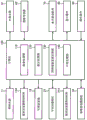
Fig. 2 shows an example of the structure of the computer 100. The computer 100 includes an inspection processing unit 110, a display processing unit 120, an illumination intensity change processing unit 130, and an alignment processing unit 140.
The inspection processing section 110 executes processing (computation, control, and the like) relating to an inspection performed by the ophthalmologic apparatus 1. The inspection processing section 110 is realized by cooperation of hardware including a processor and inspection processing software.
The examination processing unit 110 controls, for example, the illumination light source 11, the excitation filter moving mechanism 13A, the interference camera 23, the barrier filter moving mechanism 31A, and the anterior segment imaging camera 33, respectively.
The control of the illumination light source 11 includes, for example, turning on and off, changing the output light amount, and changing the output wavelength band. The control of the excitation filter moving mechanism 13A includes, for example, insertion of the excitation filter 13 into the optical path and retraction of the excitation filter 13 from the optical path.
The control of the imaging camera 23 includes, for example, exposure adjustment, gain adjustment, detection rate adjustment, and selection of a detection band (image sensor to be used). When the diaphragm 21 is an iris diaphragm, the inspection processing unit 110 controls the diaphragm 21.
The control of the blocking filter moving mechanism 31A includes, for example, insertion of the blocking filter 31 into the optical path and retraction of the blocking filter 31 from the optical path. The control of the anterior ocular segment photographing camera 33 includes, for example, exposure adjustment, gain adjustment, and detection rate adjustment.
The inspection processing unit 110 is capable of performing processing and calculation on an interference image obtained by the interference camera 23. For example, the examination processor 110 may be configured to construct a processed image from the original image acquired by the imaging system 20. The processed image may be, for example, a color map in which a parameter distribution represented by the original image is represented in a pseudo color or a map representing an area in which a parameter value falls within a predetermined range. The parameter may be, for example, the thickness of any one layer, two layers, or three layers of an oil layer, a water layer, and a mucin layer constituting the tear fluid. The processed image may be an image obtained by applying arbitrary image processing such as correction, adjustment, and enhancement to the original image.
The inspection processing unit 110 may execute the processing disclosed in patent documents 1 to 4 and other known processing. For example, the inspection processing portion 110 may perform determination of a time-series change in hue of an interference image (interference pattern), evaluation of the state of development of dry eye syndrome based on the interference pattern of each color component, evaluation of a dry spot position, evaluation of a dry spot shape, and evaluation of a moving direction of tear liquid around the dry spot.
The examination processing unit 110 can perform processing and calculation on the anterior segment image obtained by the anterior segment capturing camera 33. For example, the inspection processing section 110 can construct a processed image from the original image acquired by the anterior segment imaging system 30. As described above, the processed image may be an image obtained by applying arbitrary image processing such as correction, adjustment, and enhancement to the original image.
The display processing section 120 performs processing for displaying information on the display device 80. The display processing unit 120 is realized by cooperation of hardware including a processor and display processing software.
For example, in order to display the second information superimposed on the first information, the display processing unit 120 executes, for example, control to present the second information on the first layer, control to display the first information on the first layer, and control to display the second information on the second layer. Alternatively, the display processing section 120 may perform a process of synthesizing (embedding) the second information with the first information and a process of displaying the thus obtained synthesized information.
The illumination intensity change processing section 130 performs processing for changing the intensity of illumination light projected to the anterior segment Ea by the illumination system 10. The illumination intensity change processing unit 130 is realized by cooperation of hardware including a processor and illumination intensity change processing software.
When the tunable filter 14 is used to change the illumination intensity, the illumination intensity change processing unit 130 executes, for example, control for changing the filter characteristic of the tunable filter 14 or control for disposing any one of two or more filters on the optical path.
When the intensity of the illumination light projected to the anterior ocular segment Ea is changed by changing either one or both of the intensity and the wavelength band of the illumination light output from the illumination light source 11, the illumination intensity change processing section 130 controls the illumination light source 11.
The illumination intensity change processing unit 130 performs control for changing the illumination intensity in accordance with a signal from the operation device 90, for example. That is, the ophthalmologic apparatus 1 may be configured to manually change the illumination intensity. Here, the operation device 90 is operated by an inspector or a subject. In addition, the variable range of the illumination intensity may be set in advance to a range in which at least one of the interference imaging and the anterior segment imaging can be appropriately performed.
In the case of automatically changing the illumination intensity, for example, the illumination intensity change processing unit 130 may be configured to acquire information of the illumination intensity applied to the subject (the eye to be examined E) in the past examination from medical information (e.g., electronic medical record) related to the subject, and reproduce the illumination intensity.
As another example of the case of automatically changing the illumination intensity, the illumination intensity change processing unit 130 may be configured to cause the ophthalmologic apparatus 1 to output visual information or auditory information for inquiring the degree of dazzling of the subject when the illumination light is projected to the front eye Ea, and adjust the illumination intensity in accordance with the response of the subject.
In still another example of the case where the illumination intensity is automatically changed, the illumination intensity change processing unit 130 may be configured to adjust the illumination intensity based on a body signal of the subject when the illumination light is projected to the front eye Ea. The body signal may be, for example, miosis, brain waves, heart rate, sweating, expression, and the like. The ophthalmological apparatus 1 may comprise or be connected to a device for detecting any body signals, for example. The pupil constriction can be detected by the anterior segment imaging camera 33 and the illumination intensity change processing unit 130, for example. The electroencephalogram can be detected by an electroencephalograph, for example. The heart rate can be detected by an electrocardiograph or a pulse oximeter, for example. Perspiration can be detected, for example, by a sweat meter. The expression can be detected by the camera and illumination intensity change processing unit 130, for example. Body signals different from these examples can be detected by the device corresponding thereto.
The alignment processing section 140 performs processing related to position adjustment (alignment) of the optical system with respect to the eye E. The alignment processing section 140 is realized by cooperation of hardware including a processor and alignment processing software.
The ophthalmologic apparatus 1 can perform not only the Z-alignment but also the alignment in the X-direction and the Y-direction (XY-alignment). The alignment processing section 140 performs processing relating to Z alignment and processing relating to XY alignment.
First, processing related to Z alignment is explained. The alignment processing section 140 can perform control of the alignment light source 61 and control of the image sensor 62. The control of the aiming light source includes lighting, light-off, light quantity adjustment, aperture adjustment, and the like. The control of the image sensor 62 includes exposure adjustment, gain adjustment, detection rate adjustment, and the like.
The alignment processing unit 140 takes in the signal output from the image sensor 62, and determines the projection position of light on the light receiving surface of the image sensor 62 based on the signal. The alignment processing unit 140 obtains the position of the corneal vertex of the eye E based on the determined projection position, and moves the inspection unit 2 in the front-rear direction (Z alignment) based on the control unit moving mechanism 70.
Next, XY alignment is explained. The ophthalmologic apparatus 1 may be configured to perform XY alignment based on the anterior segment image acquired by the anterior segment photographing system 30.
For example, the alignment processing section 140 first analyzes the anterior segment image to detect a feature point (e.g., pupil center or pupil center of gravity). Next, the alignment processing section 140 calculates the offset of the feature point with respect to a predetermined position (for example, the frame center) of the frame of the anterior segment image. Next, the alignment processing unit 140 controls the unit moving mechanism 70 to move the inspection unit 2 in the left-right direction and/or the up-down direction so as to cancel the calculated misalignment (XY alignment). Thus, the feature points of the anterior segment are arranged at predetermined positions in the frame by XY alignment.
The computer 100 may include different components than those shown in fig. 2. For example, computer 100 may include a communications interface. The communication interface has a function for communicating with an external device not shown. The external device may include, for example, any of an ophthalmic device, a device (reader) that reads information from a storage medium, and a device (writer) that writes information to a storage medium. In addition, the external device may include any information processing device such as a Hospital Information System (HIS) server, a Digital Imaging and communications in Medicine (DICOM) server, a doctor terminal, a mobile terminal, a personal terminal, a cloud server, and the like.
Action
The operation of the ophthalmic apparatus 1 according to the present embodiment will be described. Fig. 4 shows an operation example of the ophthalmologic apparatus 1.
(S1: Lighting of anterior eye part)
First, the illumination light source 11 is turned on to project illumination light toward the anterior eye Ea.
(S2: adjusting the illumination intensity)
Subsequently, the intensity of the illumination light projected toward the front eye Ea is adjusted by controlling the tunable filter 14 and the like. The illumination intensity adjustment can be performed in the aforementioned manner, for example.
(S3: alignment)
Then, alignment is performed. In the present embodiment, for example, the Z alignment is performed after the XY alignment. The XY alignment and the Z alignment can be performed in the above-described manner, for example.
(S4: placing a filter for fluorescence radiography on the optical path)
Next, the excitation filter 13 and the blocking filter 31 are disposed on the corresponding optical paths, respectively.
(S5: Start-Up Formoset and anterior Ocular photography)
When the above preparation is completed, the acquisition of the images by the imaging system 20 and the anterior segment imaging by the anterior segment imaging system 30 are started.
The interference shots capture interference patterns indicative of the tear state (e.g., thickness distribution) on the cornea Ec. The imaging is performed for a predetermined time period, for example. Alternatively, the dry imaging is performed until the tear state on the cornea Ec reaches a predetermined state (for example, until the tear layer is sufficiently destroyed).
Anterior ocular segment capture is performed, for example, during at least a portion of the duration of the interventional procedure. This makes it possible to obtain an anterior segment image substantially at the same time as a certain interference image obtained by the interference photography. When the anterior segment is imaged during the entire duration of the imaging session, as in the case where the imaging session and the anterior segment are performed in parallel, an anterior segment image may be obtained that temporally corresponds to each of the interference images acquired by the imaging session.
The timing of the interference imaging can be synchronized with the timing of the anterior ocular segment imaging. For example, the interference imaging and the anterior ocular segment imaging can be performed at the same repetition timing (imaging rate, frame rate).
(S6: capturing interference image and anterior eye image)
The display processing unit 120 takes in, for example, an interference image and an anterior segment image that are acquired substantially simultaneously with each other. The display processing unit 120 may capture the interference image and the anterior segment image acquired at substantially different timings.
(S7: displaying the interference image and the anterior segment image in an overlapping manner)
The display processing unit 120 causes the display device 80 to display the interference image and the anterior segment image acquired in step S6. At this time, the display processing unit 120 displays the interference image on the anterior segment image in a superimposed manner.
In step S6, when the interference image and the anterior segment image acquired substantially simultaneously with each other are captured, the interference image can be superimposed on the anterior segment image without performing registration between these images.
On the other hand, in step S6, when the interference image and the anterior segment image acquired at substantially different timings are captured, it is desirable to perform registration between these images. Here, since the content depicted in the interference image and the content depicted in the anterior segment image are different, it is difficult to directly compare these images for registration.
Therefore, an anterior segment image (auxiliary anterior segment image) acquired substantially simultaneously with the interference image separately from the displayed anterior segment image is used. For example, the auxiliary anterior segment image may be selected based on the synchronization between the aforementioned interference imaging and anterior segment imaging. The display processing unit 120 can perform registration between the displayed anterior segment image and the auxiliary anterior segment image, and determine the offset of the latter with respect to the former. Further, the display processing unit 120 can perform registration between the interference image and the displayed anterior segment image so as to eliminate the obtained deviation. This operation example ends (End) as described above.
(modification)
In the above-described embodiment, Z alignment using an optical lever and XY alignment using an anterior segment image are performed. An example of an alignment method that can be applied instead of this alignment will be described below.
In the present modification, three-dimensional alignment (XYZ alignment) is performed based on two or more captured images acquired by capturing the anterior segment Ea from mutually different directions. Fig. 5A, 5B, and 6 show examples of structures for achieving this alignment. Fig. 5A and 5B show an example of the external appearance of the ophthalmic apparatus according to the present modification. The structure shown in fig. 6 can be applied instead of the structure shown in fig. 2.
The configuration of the ophthalmic apparatus according to the present modification may be the same as that of the ophthalmic apparatus 1 according to the above-described embodiment, except that, for example, two anterior segment cameras 300A and 300B are provided, an alignment processing unit 140A is provided instead of the alignment processing unit 140, and the alignment light source 61 and the image sensor 62 are not provided. However, the ophthalmologic apparatus of the present modification does not exclude the alignment light source 61 and the image sensor 62. In the following description, the same reference numerals as those used in the description of the ophthalmic apparatus 1 are used unless otherwise mentioned.
The ophthalmologic apparatus according to the modified example includes a jaw support for supporting the face of the subject and a forehead rest. The same applies to the ophthalmic apparatus 1 of the above embodiment.
A drive system and a processing system are housed in the base 310. For example, the unit moving mechanism 70 and the computer 100 shown in fig. 1 are accommodated in the base 310.
A housing 320 provided on the base 310 accommodates an optical system and a driving system. For example, the inspection unit 2 shown in fig. 1 is accommodated in the housing 320.
At least the lens 41 is housed in a lens housing 330 protruding from the front surface of the housing 320.
The display device 80 shown in fig. 1 may be provided to the housing 320. In addition, the operation device 90 may be disposed on at least one of the base 310 and the housing 320.
Two anterior eye cameras 300A, 300B are provided on the front surface of the housing 320. The two anterior segment cameras 300A, 300B capture the anterior segment Ea of the eye E from two directions different from each other (two positions different from each other).
The two anterior segment cameras 300A and 300B each include an image pickup device such as a CCD image sensor or a CMOS image sensor. In the present modification, two anterior segment cameras 300A and 300B are provided on the subject-side surface of the housing 320. As shown in fig. 5A, two anterior segment cameras 300A, 300B are disposed at positions other than the optical path passing through the lens 41.
In the present modification, two anterior segment cameras 300A and 300B are provided, but the number of anterior segment cameras may be any number of two or more. However, considering the processing load for the calculation of the three-dimensional alignment, it is sufficient if the anterior segment can be imaged from two different directions (however, the present invention is not limited thereto). Alternatively, a movable anterior segment camera may be provided to sequentially perform anterior segment photographing from two or more different positions.
In the present modification, two anterior segment cameras 300A, 300B are separately provided from the anterior segment imaging system 30, but one of two or more anterior segment cameras may be the anterior segment imaging system 30.
When two or more anterior segment cameras are provided, the anterior segment can be photographed substantially simultaneously from two or more different directions. "substantially simultaneously" indicates a case where the photographing timings by two or more anterior segment cameras are simultaneously, and for example, a case where there is a deviation in the photographing timing to such an extent that the eyeball motion can be ignored is also permitted. By performing such substantially simultaneous imaging, two or more anterior segment images of the eye to be examined at substantially the same position and orientation can be acquired.
The image capturing by the two or more anterior ocular cameras may be moving image capturing or still image capturing. In the case of moving image shooting, the above-described substantially simultaneous anterior segment shooting can be achieved by performing control so that shooting start timings match, or by controlling the frame rate and/or the shooting timing of each frame. On the other hand, in the case of still picture shooting, by performing control so that shooting timings coincide with each other, it is possible to realize substantially simultaneous anterior segment shooting.
Two anterior segment images acquired substantially simultaneously by the two anterior segment cameras 300A, 300B are transmitted to the computer 100.
The alignment processing unit 140A analyzes two captured images (anterior segment images) obtained by the two anterior segment cameras 300A and 300B substantially simultaneously, and obtains the three-dimensional position of the eye E.
The analysis may include the determination of feature locations and the calculation of three-dimensional locations, for example, as disclosed in U.S. patent application publication No. 2015/0085252. Further, before these processes, a process of correcting distortion of the captured images obtained by each of the two anterior segment cameras 300A, 300B may be performed.
In the determination of the characteristic position, the alignment processing unit 140A analyzes, for example, two anterior segment images acquired by the two anterior segment cameras 300A and 300B substantially simultaneously, and determines a position (also referred to as a characteristic position) in the captured image corresponding to a predetermined characteristic portion of the anterior segment Ea. The feature is typically the pupil center (or pupil center of gravity).
To specify the position of the pupil center, the alignment processing unit 140A first specifies an image region (pupil region) corresponding to the pupil of the eye E based on the distribution of pixel values (for example, luminance values) of the captured image. Since the pupil is usually depicted at a lower luminance than other portions, the pupil area can be specified by searching for an image area with a low luminance. At this time, the pupil region may be determined in consideration of the shape of the pupil. That is, the pupil area can be specified by searching for a substantially circular image area with low luminance.
Next, the alignment processing unit 140A specifies the center position of the pupil area thus specified. As described above, since the pupil is substantially circular, the contour of the pupil region can be determined, the center position of the contour (or its approximate circle or approximate ellipse) can be determined, and this can be used as the pupil center.
In the calculation of the three-dimensional position, the alignment processing unit 140A calculates the three-dimensional position of the feature portion of the eye E based on the positions of the two anterior segment cameras 300A and 300B and the feature positions in the two captured images determined by the above-described processing. This operation is performed by using trigonometry as described in U.S. patent application publication No. 2015/0085252.
The alignment processing unit 140A performs control of the unit moving mechanism 70 (corresponding to XY alignment) so that the optical axis of the optical system coincides with the axis of the eye E based on the three-dimensional position of the eye E calculated in this way, and performs control of the unit moving mechanism 70 (corresponding to Z alignment) so that the distance between the eye E and the optical system coincides with a predetermined focal length.
Action and effect
The function and effect of the ophthalmic device of several exemplary embodiments are described.
An ophthalmic apparatus of an exemplary embodiment includes an illumination system, an imaging system, an anterior ocular segment imaging system, a first optical path coupling element, and a control section.
The illumination system projects illumination light output from the light source to an anterior ocular segment of the eye to be examined. In the above example, the lighting system 10 corresponds to a lighting system. The illumination system 10 is configured to project illumination light output from the illumination light source 11 to the anterior ocular segment Ea.
The imaging system captures an interference pattern formed on the cornea by illumination light projected to the anterior segment by the illumination system. In the above example, the imaging system 20 corresponds to an imaging system. The interference imaging system 20 captures an interference image by imaging an interference pattern formed on the cornea Ec by illumination light projected to the anterior segment Ea by the illumination system 10.
The anterior segment imaging system images an anterior segment on which illumination light is projected by the illumination system. In the above example, the anterior segment imaging system 30 corresponds to an anterior segment imaging system. The anterior segment imaging system 30 images the anterior segment Ea on which the illumination light is projected by the illumination system 10. The anterior segment imaging system 30 is configured to image a wide range of the anterior segment Ea from the front.
The first optical path coupling element couples an optical path of the imaging system with an optical path of the anterior ocular segment imaging system. In the above illustration, the optical path coupling element 51 corresponds to a first optical path coupling element. The optical path coupling element 51 is configured to couple an optical path of the imaging system 20 with an optical path of the anterior ocular segment imaging system 30. Further, the optical path coupling element 51 couples the optical path of the illumination system 10 and the optical path of the anterior ocular segment photographing system 30.
The control unit displays an interference image acquired by the interference imaging system and an anterior segment image acquired by the anterior segment imaging system on the display device in a superimposed manner. The interference image displayed may be an original image acquired by an imaging system or a processed image obtained from the original image. The display device may be a component of the ophthalmic device or may be a peripheral device of the ophthalmic device.
In the above example, the computer 100 (particularly, the display processing unit 120) corresponds to the control unit. The computer 100 is configured to display an interference image acquired by the imaging system 20 and an anterior segment image acquired by the anterior segment imaging system 30 on the display device 80 in a superimposed manner.
According to an exemplary embodiment configured as described above, the imaging system and the anterior ocular segment imaging system are provided separately, and optical paths of the two are coupled to each other by the first optical path coupling element, so that the imaging system and the anterior ocular segment imaging can be performed substantially simultaneously. This reduces the possibility of occurrence of a misalignment between the interference image and the anterior segment image due to eye movement or body movement.
Furthermore, according to an exemplary embodiment, an anterior segment imaging system provided separately from the imaging system may be capable of imaging a wide range of the anterior segment. This reduces the possibility of missing an abnormality occurring at the end of the cornea, and enables efficient examination.
Further, according to the exemplary embodiment, the interference image showing the state of the tear can be displayed in superimposition with the anterior segment image, and the abnormal position and distribution of the tear can be displayed in superimposition with the anterior segment image. This makes it possible to present the user with a more easy (intuitive) understanding of the abnormality occurrence position.
As described above, according to the exemplary embodiment, the abnormality occurrence position of the tear state can be presented with good positional accuracy over a wide range of the anterior segment.
The ophthalmic device of several exemplary embodiments may further include a first lens group disposed on a side of the eye to be inspected with respect to the first optical path coupling element and a second lens group disposed on an opposite side of the eye to be inspected with respect to the first optical path coupling element. Here, the first lens group and the second lens group may be configured to function as object lenses of an imaging system for an anterior segment, and the first lens group may be configured to function as object lenses of an imaging system for an anterior segment.
In the above example, two lenses 41 and 42 correspond to the first lens group, and two lenses 43 and 44 correspond to the second lens group. The four lenses 41 to 44 function as object lenses of the imaging system 22, and the two lenses 41 and 42 function as object lenses of the anterior segment imaging system 30.
In some exemplary embodiments, a lens closest to the first optical path coupling element among lenses included in the anterior segment photographing system may be disposed at or near a focal position of the first lens group.
In the above example, the lens closest to the optical path coupling element 51 among the lenses 32 included in the anterior segment imaging system 30 is disposed at or near the focal position of the first lens group composed of the two lenses 41 and 42.
According to the exemplary embodiment configured as described above, at least the following two effects are obtained. First, with respect to an imaging system, illumination light is made incident on each position of the cornea substantially perpendicularly, and reflected light from each position of the cornea is detected to enter in the opposite direction along substantially the same path as the incident path of the illumination light to the position. As a result, the path of the illumination light and the path of the reflected light substantially coincide with each other for each position of the cornea, and as a result, the tear state distribution on the curved cornea can be accurately captured from the direction perpendicular to the curved surface.
Second, in the anterior segment imaging system, the anterior segment imaging system can be disposed in the vicinity of the first optical path coupling element, and the anterior segment imaging system (lens) can be disposed at or near the rear focal position of the first lens group. This can enlarge the imaging field of view of the anterior segment imaging system.
The ophthalmic devices of several exemplary embodiments may also include a second optical path coupling element coupling the optical path of the illumination system and the optical path of the imaging system. In the above illustration, the optical path coupling element 53 corresponds to a second optical path coupling element. The optical path coupling element 53 is configured to couple an optical path of the illumination system 10 and an optical path of the imaging system 20.
In several exemplary embodiments, the first optical path coupling element and the second optical path coupling element may each be a beam splitter. Further, return light of the illumination light for imaging the interference pattern may be reflected by the first optical path coupling element and the second optical path coupling element, respectively, and may be guided to the imaging element of the imaging system.
In the above example, the optical path coupling element 51 and the optical path coupling element 53 are beam splitters (half mirrors and the like), respectively. The return light of the illumination light configured to image the interference pattern is reflected by the optical path coupling element 51 and the optical path coupling element 53, respectively, and is guided to the imaging camera 23 corresponding to the imaging element.
According to the exemplary embodiment configured as described above, the optical system can be made compact, and interference of light when passing through the beam splitter can be avoided, so that the interference pattern generated on the cornea can be detected with high accuracy.
The ophthalmic apparatus according to some exemplary embodiments may further include an illumination intensity changing section that changes an intensity of the illumination light projected to the anterior segment. In the above example, the variable filter 14 and the illumination intensity change processing unit 130 correspond to an illumination intensity changing unit.
According to the exemplary embodiment thus configured, inspection can be performed using light of appropriate intensity. For example, in an examination that takes a certain amount of time, such as a tear layer destruction time (BUT) examination, the possibility of the subject closing the eye due to the eye puncture can be reduced, and the burden on the subject can also be reduced.
The ophthalmic device of several exemplary embodiments may further include an excitation filter that generates excitation light of a fluorescent agent administered to the anterior segment from the illumination light, and a blocking filter that selectively passes fluorescence generated by the fluorescent agent receiving the excitation light. In the above example, the excitation filter 13 corresponds to an excitation filter, and the blocking filter 31 corresponds to a blocking filter.
According to the exemplary embodiment configured as described above, since the fluorescence contrast imaging of the anterior segment can be performed, the corneal state and the tear state can be observed suitably.
The ophthalmic devices of several exemplary embodiments may include means for alignment. The inspection can be facilitated by the alignment. Examples of structures for alignment are as follows.
As a first example, the ophthalmic devices of several exemplary embodiments may include a projection system, a detection system, and a first alignment portion. The projection system projects the alignment light toward the anterior eye along a direction inclined with respect to an optical axis of an optical path from the first optical path coupling element toward the eye to be inspected. The detection system detects reflected light of the alignment light projected to the anterior segment by the projection system. The first alignment section performs alignment in a direction along the optical axis based on an output from the detection system.
In the above examples, the alignment light source 61, the lens 42, and the lens 41 correspond to a projection system. The lens 41, the lens 42, and the image sensor 62 correspond to a detection system. The unit moving mechanism 70 and the alignment processing unit 140 correspond to a first alignment unit. Z-alignment is achieved by these components.
In a first example, the projection system may include an alignment light source that outputs alignment light. In addition, the detection system may include an image sensor that detects reflected light of the alignment light. The alignment light source and the image sensor may be disposed on the opposite side of the eye to be inspected with respect to the first optical path coupling element.
In the above example, the alignment light source 61 corresponds to an alignment light source, and the image sensor 62 corresponds to an image sensor. The alignment light source 61 and the image sensor 62 are disposed on the opposite side of the eye E to be inspected with respect to the optical path coupling element 51, that is, on the anterior segment imaging system 30 side. The optical path coupling element 51 is formed with a notch, an opening, a light-transmitting portion, and the like, and light can be configured to pass through the optical path coupling element 51 through the notch, the opening, the light-transmitting portion, and the like.
As a second example, the ophthalmic devices of several exemplary embodiments may further include a second alignment portion. The second alignment section performs alignment in a direction orthogonal to the optical axis of the optical path from the first optical path coupling element toward the eye to be inspected, based on the anterior segment image acquired by the anterior segment photographing system.
In the above examples, the unit moving mechanism 70 and the alignment processing section 140 correspond to a second alignment section. XY alignment is achieved by these components.
As a third example, the ophthalmic apparatus of several exemplary embodiments includes two or more photographing sections and a third alignment section. The two or more imaging units image the anterior segment of the eye from different directions. The third alignment unit performs three-dimensional alignment based on two or more captured images acquired by the two or more imaging units, respectively.
In the above example, the two anterior segment cameras 300A and 300B correspond to two or more imaging units, and the unit moving mechanism 70 and the alignment processing unit 140A correspond to a third alignment unit. There are these components to achieve three-dimensional alignment (XYZ alignment).
Description of the reference numerals
1 ophthalmic device
2 inspection Unit
10 illumination system
11 illumination light source
13 excitation filter
13A excitation filter moving mechanism
14 tunable filter
20-interference shooting system
23-interference shooting camera
30 anterior eye shooting system
31 blocking filter
31A blocking filter moving mechanism
32 lens
33 anterior eye shooting camera
41. 42, 43, 44 lens
51. 53 optical path coupling element
61 aligning the light source
62 image sensor
70 unit moving mechanism
80 display device
100 computer
110 inspection processing part
120 display processing unit
130 illumination intensity change processing unit
140 to the processing section.
Claims (11)
1. An ophthalmic device, comprising:
an illumination system that projects illumination light output from the light source to an anterior eye portion of the eye to be examined;
an interference imaging system for imaging an interference pattern formed on a cornea by the illumination light;
an anterior segment photographing system for photographing the anterior segment on which the illumination light is projected;
a first optical path coupling element coupling an optical path of the imaging system with an optical path of the anterior ocular segment imaging system; and
and a control unit configured to display an interference image acquired by the imaging system and an anterior segment image acquired by the anterior segment imaging system on a display device in a superimposed manner.
2. An ophthalmic device according to claim 1,
the ophthalmic device further comprises:
a first lens group disposed on the eye side with respect to the first optical path coupling element; and
a second lens group disposed on the opposite side of the eye to be inspected with respect to the first optical path coupling element,
the first lens group and the second lens group function as object lenses of the imaging system,
the first lens group functions as an objective lens of the anterior ocular segment photographing system.
3. An ophthalmic device according to claim 2,
the most lens on the first optical path coupling element side among the lenses included in the anterior segment imaging system is disposed at or near the focal position of the first lens group.
4. An ophthalmic device according to any one of claims 1 to 3,
the ophthalmic apparatus also includes a second optical path coupling element coupling an optical path of the illumination system and an optical path of the imaging system.
5. An ophthalmic device according to claim 4,
the first and second optical path coupling elements are each beam splitters,
return light of the illumination light for imaging the interference pattern is reflected by the first and second optical path coupling elements, respectively, and is guided to an imaging element of the imaging system.
6. An ophthalmic device according to any one of claims 1 to 5,
the ophthalmic apparatus further includes an illumination intensity changing section that changes an intensity of the illumination light projected to the anterior segment.
7. An ophthalmic device according to any one of claims 1 to 6,
the ophthalmic device further comprises:
an excitation filter that generates excitation light of a fluorescent agent administered to the anterior eye from the illumination light; and
a blocking filter selectively passing fluorescence generated by the fluorescent agent subjected to the excitation light.
8. An ophthalmic device according to any one of claims 1 to 7,
the ophthalmic device further comprises:
a projection system that projects alignment light toward the anterior eye portion in a direction inclined with respect to an optical axis of an optical path from the first optical path coupling element toward the eye to be inspected;
a detection system that detects reflected light of the alignment light at the anterior segment; and
a first alignment section that performs alignment in a direction along the optical axis based on an output from the detection system.
9. An ophthalmic device according to claim 8,
the projection system includes an alignment light source that outputs the alignment light,
the detection system includes an image sensor that detects the reflected light,
the alignment light source and the image sensor are disposed on the opposite side of the eye to be inspected with respect to the first optical path coupling element.
10. An ophthalmic device according to any one of claims 1 to 9,
the ophthalmologic apparatus further includes a second alignment section that performs alignment in a direction orthogonal to an optical axis of an optical path from the first optical path coupling element toward the eye to be inspected, based on the anterior segment image acquired by the anterior segment photographing system.
11. An ophthalmic device according to any one of claims 1 to 7,
the ophthalmic device further comprises:
two or more imaging units that image the anterior segment from different directions; and
and a third alignment unit that performs three-dimensional alignment based on the two or more captured images acquired by the two or more imaging units, respectively.
Applications Claiming Priority (3)
| Application Number | Priority Date | Filing Date | Title |
|---|---|---|---|
| US16/200,676 US11013401B2 (en) | 2018-11-27 | 2018-11-27 | Ophthalmologic apparatus |
| US16/200,676 | 2018-11-27 | ||
| PCT/JP2019/046321 WO2020111103A1 (en) | 2018-11-27 | 2019-11-27 | Ophthalmological device |
Publications (1)
| Publication Number | Publication Date |
|---|---|
| CN113423323A true CN113423323A (en) | 2021-09-21 |
Family
ID=70771105
Family Applications (1)
| Application Number | Title | Priority Date | Filing Date |
|---|---|---|---|
| CN201980090331.XA Pending CN113423323A (en) | 2018-11-27 | 2019-11-27 | Ophthalmic Devices |
Country Status (5)
| Country | Link |
|---|---|
| US (1) | US11013401B2 (en) |
| EP (1) | EP3888527A4 (en) |
| JP (4) | JP7212063B2 (en) |
| CN (1) | CN113423323A (en) |
| WO (1) | WO2020111103A1 (en) |
Families Citing this family (4)
| Publication number | Priority date | Publication date | Assignee | Title |
|---|---|---|---|---|
| JP7321678B2 (en) * | 2018-06-13 | 2023-08-07 | 株式会社トプコン | slit lamp microscope and ophthalmic system |
| WO2022015915A1 (en) * | 2020-07-16 | 2022-01-20 | Boston Eye Diagnostics, Inc. | System and method for acquisition and quantification of images with ocular staining |
| WO2024173940A1 (en) * | 2023-02-17 | 2024-08-22 | Berlin Michael S | Three dimensional imaging for surgery |
| CN120957650A (en) * | 2023-04-14 | 2025-11-14 | Ams-欧司朗有限公司 | Head-mounted device for detecting metabolic states in the eye |
Citations (7)
| Publication number | Priority date | Publication date | Assignee | Title |
|---|---|---|---|---|
| JP2000237135A (en) * | 1999-02-18 | 2000-09-05 | Nidek Co Ltd | Ophthalmologic device |
| US20110282331A1 (en) * | 2010-05-13 | 2011-11-17 | Oprobe, Llc | Optical coherence tomography with multiple imaging instruments |
| JP2012161428A (en) * | 2011-02-04 | 2012-08-30 | Tomey Corporation | Ophthalmologic apparatus |
| JP2013135965A (en) * | 2013-04-08 | 2013-07-11 | Canon Inc | Ophthalmic apparatus |
| US20150085252A1 (en) * | 2012-05-01 | 2015-03-26 | Kabushiki Kaisha Topcon | Ophthalmologic apparatus |
| JP2017136212A (en) * | 2016-02-03 | 2017-08-10 | 株式会社ニデック | Ophthalmologic apparatus |
| JP2018149284A (en) * | 2017-03-14 | 2018-09-27 | 株式会社トプコン | Tear film thickness measurement apparatus and method |
Family Cites Families (12)
| Publication number | Priority date | Publication date | Assignee | Title |
|---|---|---|---|---|
| JPH06237901A (en) * | 1993-02-17 | 1994-08-30 | Canon Inc | Fundus camera |
| JP3586039B2 (en) | 1996-04-26 | 2004-11-10 | 興和株式会社 | Ophthalmic equipment |
| JP3718104B2 (en) | 2000-05-01 | 2005-11-16 | 株式会社ニデック | Ophthalmic equipment |
| JP4404648B2 (en) | 2004-01-27 | 2010-01-27 | 株式会社ニデック | Ophthalmic equipment |
| WO2007004383A1 (en) | 2005-07-01 | 2007-01-11 | Kowa Kabushiki Kaisha | Ophthalmologic photographing device |
| JP5038925B2 (en) * | 2008-01-29 | 2012-10-03 | 則彦 横井 | Ophthalmic measuring device |
| JP6007466B2 (en) * | 2010-12-27 | 2016-10-12 | 株式会社ニデック | Corneal shape measuring device |
| US8641194B2 (en) * | 2011-07-08 | 2014-02-04 | Johnson & Johnson Vision Care, Inc. | System for in vivo analysis of tear film in the human eye via phase shifting interferometry |
| JP2016007433A (en) * | 2014-06-25 | 2016-01-18 | 株式会社ニデック | Ophthalmologic apparatus |
| WO2016067366A1 (en) * | 2014-10-28 | 2016-05-06 | パイオニア株式会社 | Observation device, observation method, and computer program |
| JP2017169672A (en) | 2016-03-22 | 2017-09-28 | 株式会社トプコン | Ophthalmologic photographing apparatus |
| JP6901264B2 (en) * | 2017-01-11 | 2021-07-14 | 株式会社トプコン | Ophthalmic equipment |
-
2018
- 2018-11-27 US US16/200,676 patent/US11013401B2/en active Active
-
2019
- 2019-11-27 EP EP19888349.8A patent/EP3888527A4/en active Pending
- 2019-11-27 JP JP2020557764A patent/JP7212063B2/en active Active
- 2019-11-27 WO PCT/JP2019/046321 patent/WO2020111103A1/en not_active Ceased
- 2019-11-27 CN CN201980090331.XA patent/CN113423323A/en active Pending
-
2023
- 2023-01-11 JP JP2023002600A patent/JP7488924B2/en active Active
-
2024
- 2024-05-09 JP JP2024076277A patent/JP7606032B2/en active Active
- 2024-05-09 JP JP2024076278A patent/JP7622279B2/en active Active
Patent Citations (7)
| Publication number | Priority date | Publication date | Assignee | Title |
|---|---|---|---|---|
| JP2000237135A (en) * | 1999-02-18 | 2000-09-05 | Nidek Co Ltd | Ophthalmologic device |
| US20110282331A1 (en) * | 2010-05-13 | 2011-11-17 | Oprobe, Llc | Optical coherence tomography with multiple imaging instruments |
| JP2012161428A (en) * | 2011-02-04 | 2012-08-30 | Tomey Corporation | Ophthalmologic apparatus |
| US20150085252A1 (en) * | 2012-05-01 | 2015-03-26 | Kabushiki Kaisha Topcon | Ophthalmologic apparatus |
| JP2013135965A (en) * | 2013-04-08 | 2013-07-11 | Canon Inc | Ophthalmic apparatus |
| JP2017136212A (en) * | 2016-02-03 | 2017-08-10 | 株式会社ニデック | Ophthalmologic apparatus |
| JP2018149284A (en) * | 2017-03-14 | 2018-09-27 | 株式会社トプコン | Tear film thickness measurement apparatus and method |
Also Published As
| Publication number | Publication date |
|---|---|
| JP2024097905A (en) | 2024-07-19 |
| JP7622279B2 (en) | 2025-01-27 |
| WO2020111103A1 (en) | 2020-06-04 |
| JP7488924B2 (en) | 2024-05-22 |
| JP7212063B2 (en) | 2023-01-24 |
| JP2024105457A (en) | 2024-08-06 |
| JPWO2020111103A1 (en) | 2021-10-14 |
| US11013401B2 (en) | 2021-05-25 |
| US20200163545A1 (en) | 2020-05-28 |
| JP7606032B2 (en) | 2024-12-24 |
| JP2023033406A (en) | 2023-03-10 |
| EP3888527A1 (en) | 2021-10-06 |
| EP3888527A4 (en) | 2022-08-24 |
Similar Documents
| Publication | Publication Date | Title |
|---|---|---|
| JP7622279B2 (en) | Ophthalmic Equipment | |
| CN113347915B (en) | Ophthalmic device | |
| WO2014103646A1 (en) | Ophthalmology device | |
| JP7027698B2 (en) | Ophthalmologic photography equipment | |
| CN110811536A (en) | Ophthalmic device and control method thereof | |
| JP7117873B2 (en) | ophthalmic equipment | |
| JP6901264B2 (en) | Ophthalmic equipment | |
| JP7266375B2 (en) | Ophthalmic device and method of operation thereof | |
| CN116421136B (en) | Ophthalmic device | |
| CN116421137B (en) | Ophthalmic device | |
| JP7550586B2 (en) | Ophthalmic device and method of operation thereof | |
| JP2021166817A (en) | Ophthalmologic apparatus | |
| JP7250626B2 (en) | Ophthalmic device and control method for ophthalmic device | |
| JP7794589B2 (en) | ophthalmology equipment | |
| JP7638344B2 (en) | Ophthalmic Equipment | |
| JP7288110B2 (en) | ophthalmic equipment | |
| JP2020199210A (en) | Ophthalmologic apparatus and method of controlling ophthalmologic apparatus | |
| JP7553190B2 (en) | Ophthalmic device and method of operation thereof | |
| JP6959158B2 (en) | Ophthalmic equipment | |
| JP2022071191A (en) | Ophthalmologic apparatus and control method thereof | |
| JP2022109637A (en) | Ophthalmic imaging device and mirror housing | |
| JP2024146323A (en) | Fundus photography device and fundus photography control program | |
| JP2022044645A (en) | Ophthalmic equipment | |
| JP2021183277A (en) | Ophthalmologic apparatus |
Legal Events
| Date | Code | Title | Description |
|---|---|---|---|
| PB01 | Publication | ||
| PB01 | Publication | ||
| SE01 | Entry into force of request for substantive examination | ||
| SE01 | Entry into force of request for substantive examination | ||
| RJ01 | Rejection of invention patent application after publication |
Application publication date: 20210921 |
|
| RJ01 | Rejection of invention patent application after publication |