[go: up one dir, main page]

CN113404474A - Vapor source system based on vapor-liquid ejector supercharging flash evaporation technology - Google Patents

Vapor source system based on vapor-liquid ejector supercharging flash evaporation technology Download PDF

Info

Publication number
CN113404474A
CN113404474A CN202110785694.4A CN202110785694A CN113404474A CN 113404474 A CN113404474 A CN 113404474A CN 202110785694 A CN202110785694 A CN 202110785694A CN 113404474 A CN113404474 A CN 113404474A
Authority
CN
China
Prior art keywords
steam
heater
vapor
source system
liquid ejector
Prior art date
Legal status (The legal status is an assumption and is not a legal conclusion. Google has not performed a legal analysis and makes no representation as to the accuracy of the status listed.)
Pending
Application number
CN202110785694.4A
Other languages
Chinese (zh)
Inventor
杨勇
张兴尧
谢泽隆
张禹哲
张琨
沈胜强
Current Assignee (The listed assignees may be inaccurate. Google has not performed a legal analysis and makes no representation or warranty as to the accuracy of the list.)
Dalian University of Technology
Dalian Ocean University
Original Assignee
Dalian University of Technology
Dalian Ocean University
Priority date (The priority date is an assumption and is not a legal conclusion. Google has not performed a legal analysis and makes no representation as to the accuracy of the date listed.)
Filing date
Publication date
Application filed by Dalian University of Technology, Dalian Ocean University filed Critical Dalian University of Technology
Priority to CN202110785694.4A priority Critical patent/CN113404474A/en
Priority to PCT/CN2021/113134 priority patent/WO2023284061A1/en
Publication of CN113404474A publication Critical patent/CN113404474A/en
Priority to US17/946,131 priority patent/US12228280B2/en
Pending legal-status Critical Current

Links

Images

Classifications

    • EFIXED CONSTRUCTIONS
    • E21EARTH OR ROCK DRILLING; MINING
    • E21BEARTH OR ROCK DRILLING; OBTAINING OIL, GAS, WATER, SOLUBLE OR MELTABLE MATERIALS OR A SLURRY OF MINERALS FROM WELLS
    • E21B43/00Methods or apparatus for obtaining oil, gas, water, soluble or meltable materials or a slurry of minerals from wells
    • E21B43/16Enhanced recovery methods for obtaining hydrocarbons
    • E21B43/24Enhanced recovery methods for obtaining hydrocarbons using heat, e.g. steam injection
    • FMECHANICAL ENGINEERING; LIGHTING; HEATING; WEAPONS; BLASTING
    • F22STEAM GENERATION
    • F22BMETHODS OF STEAM GENERATION; STEAM BOILERS
    • F22B1/00Methods of steam generation characterised by form of heating method
    • F22B1/02Methods of steam generation characterised by form of heating method by exploitation of the heat content of hot heat carriers
    • F22B1/028Steam generation using heat accumulators
    • FMECHANICAL ENGINEERING; LIGHTING; HEATING; WEAPONS; BLASTING
    • F22STEAM GENERATION
    • F22BMETHODS OF STEAM GENERATION; STEAM BOILERS
    • F22B1/00Methods of steam generation characterised by form of heating method
    • F22B1/02Methods of steam generation characterised by form of heating method by exploitation of the heat content of hot heat carriers
    • F22B1/18Methods of steam generation characterised by form of heating method by exploitation of the heat content of hot heat carriers the heat carrier being a hot gas, e.g. waste gas such as exhaust gas of internal-combustion engines
    • FMECHANICAL ENGINEERING; LIGHTING; HEATING; WEAPONS; BLASTING
    • F22STEAM GENERATION
    • F22DPREHEATING, OR ACCUMULATING PREHEATED, FEED-WATER FOR STEAM GENERATION; FEED-WATER SUPPLY FOR STEAM GENERATION; CONTROLLING WATER LEVEL FOR STEAM GENERATION; AUXILIARY DEVICES FOR PROMOTING WATER CIRCULATION WITHIN STEAM BOILERS
    • F22D7/00Auxiliary devices for promoting water circulation
    • F22D7/06Rotary devices, e.g. propellers
    • F22D7/08Arrangements of pumps, e.g. outside the boilers
    • YGENERAL TAGGING OF NEW TECHNOLOGICAL DEVELOPMENTS; GENERAL TAGGING OF CROSS-SECTIONAL TECHNOLOGIES SPANNING OVER SEVERAL SECTIONS OF THE IPC; TECHNICAL SUBJECTS COVERED BY FORMER USPC CROSS-REFERENCE ART COLLECTIONS [XRACs] AND DIGESTS
    • Y02TECHNOLOGIES OR APPLICATIONS FOR MITIGATION OR ADAPTATION AGAINST CLIMATE CHANGE
    • Y02ATECHNOLOGIES FOR ADAPTATION TO CLIMATE CHANGE
    • Y02A20/00Water conservation; Efficient water supply; Efficient water use
    • Y02A20/124Water desalination

Landscapes

  • Engineering & Computer Science (AREA)
  • Physics & Mathematics (AREA)
  • Life Sciences & Earth Sciences (AREA)
  • Thermal Sciences (AREA)
  • Mechanical Engineering (AREA)
  • General Engineering & Computer Science (AREA)
  • Geology (AREA)
  • Mining & Mineral Resources (AREA)
  • Sustainable Development (AREA)
  • Sustainable Energy (AREA)
  • Fluid Mechanics (AREA)
  • Environmental & Geological Engineering (AREA)
  • General Life Sciences & Earth Sciences (AREA)
  • Geochemistry & Mineralogy (AREA)
  • Chemical & Material Sciences (AREA)
  • Combustion & Propulsion (AREA)
  • Heat Treatment Of Water, Waste Water Or Sewage (AREA)
  • Vaporization, Distillation, Condensation, Sublimation, And Cold Traps (AREA)

Abstract

一种基于汽液喷射器增压闪蒸技术的汽源系统,其属于余热利用和蒸汽产生的技术领域。该系统包括汽液喷射器、闪蒸罐与加热器,汽液喷射器采用高压蒸汽将闪蒸罐内抽吸而出的低压水升温、升压,经加热器升温后,进入闪蒸罐后闪蒸为低压饱和蒸汽,未闪蒸的饱和水在闪蒸罐底部汇集,经底部的引出管与汽液喷射器引射入口联通,实现循环增压闪蒸。同时补水泵将低温水送至闪蒸罐,保证汽源系统的连续稳定运行;加热器的加热热源为蒸汽锅炉的尾部烟气或其他可利用的中低温余热。该系统以少部分高压蒸汽产生多倍的低压闪蒸饱和蒸汽,并实现锅炉尾部烟气等余热的回收利用,提升工艺用汽的经济性,为稠油热采、海水淡化或污水处理等设备提供灵活可调的汽源。

Figure 202110785694

A steam source system based on a vapor-liquid ejector booster flash technology belongs to the technical field of waste heat utilization and steam generation. The system includes a vapor-liquid ejector, a flash tank and a heater. The vapor-liquid ejector uses high-pressure steam to heat up and increase the pressure of the low-pressure water pumped out of the flash tank. After being heated by the heater, it enters the flash tank. The flash evaporation is low pressure saturated steam, and the unflashed saturated water is collected at the bottom of the flash tank, and communicated with the injection inlet of the vapor-liquid ejector through the extraction pipe at the bottom to realize the cyclic pressurized flash evaporation. At the same time, the make-up pump sends low-temperature water to the flash tank to ensure the continuous and stable operation of the steam source system; the heating source of the heater is the tail flue gas of the steam boiler or other available medium and low temperature waste heat. The system uses a small part of high-pressure steam to generate multiple times of low-pressure flash saturated steam, and realizes the recovery and utilization of waste heat such as boiler tail flue gas, improving the economy of process steam, and is suitable for heavy oil thermal recovery, seawater desalination or sewage treatment equipment. Provide flexible and adjustable steam source.

Figure 202110785694

Description

Vapor source system based on vapor-liquid ejector supercharging flash evaporation technology
Technical Field
The invention relates to a steam source system based on a steam-liquid ejector supercharging flash technology, and belongs to the technical field of thickened oil thermal recovery, seawater desalination and sewage treatment.
Background
The oil exploitation in China already enters a thick oil thermal exploitation stage, the thick oil thermal exploitation needs to consume a large amount of steam and fresh water, and a steam source system which can supply medium and low pressure steam to large and medium-sized multi-effect evaporation or multi-stage flash evaporation and other thermal seawater desalination or sewage treatment devices is important auxiliary equipment for the thick oil thermal exploitation.
The steam injection boiler for heavy oil thermal recovery generally takes crude oil, diesel oil and natural gas as fuels, generates high-temperature and high-pressure saturated steam or superheated steam of 10-21MPa, injects the high-temperature and high-pressure saturated steam or superheated steam into an oil well, heats the crude oil in an oil layer to reduce the viscosity of the heavy oil so as to greatly improve the recovery ratio of the heavy oil, and the evaporation capacity generally reaches 18t/h or more. If the high-temperature high-pressure steam generated by the steam injection boiler is directly used for seawater desalination or a sewage treatment device after temperature reduction and pressure reduction, high-quality fresh water is produced for the steam injection boiler, the energy loss is large, and the water-making economy is not high.
In addition, the exhaust gas temperature of the small-sized steam boiler is higher, generally 140-270 ℃, the waste heat recovery value is higher, but the exhaust gas quantity is smaller, the waste heat dispersion recovery cost is higher, and a universal technology with higher heat economy does not exist. If the tail flue gas waste heat of the small-sized steam boiler is used for hot method seawater desalination or a sewage treatment device to produce high-quality boiler water supplement, the water supplement quality of the boiler can be greatly improved, the scaling and blocking risks of the boiler are reduced, the heat efficiency and the service life of the boiler are obviously improved, the energy utilization efficiency of fossil fuels is improved, the water making cost of hot method seawater desalination or sewage treatment is greatly reduced, obvious economic benefits and environmental benefits are brought, and the energy development strategy of 'carbon peak reaching and carbon neutralization' is realized as early as possible in China.
To this end, the patent is provided, namely a steam source system based on a steam-liquid ejector supercharging flash technology.
Disclosure of Invention
The invention aims to provide a vapor source system based on a vapor-liquid ejector supercharging flash technology. Aiming at the problems that high-temperature high-pressure steam generated by a thick oil thermal recovery steam injection boiler is directly used for a multi-effect evaporation or multi-stage flash evaporation and other thermal seawater desalination or sewage treatment processes after temperature reduction and pressure reduction, the energy loss is large, and the water production economy is not high, the high-pressure steam is adopted to drive a steam-liquid ejector, low-pressure water in a flash evaporation tank is sucked, the pressure and the temperature are improved, then the low-pressure water is sent into a heater to be further heated to a saturated or nearly saturated state, multiple times of low-pressure steam is flashed in the flash evaporation tank, and the thermal economy of a low-pressure steam utilization process is improved. The heater of the steam source system can adopt the tail flue gas of the boiler as a heat source, and the waste heat utilization of the flue gas of the boiler is realized in the forms of a split type heat pipe heater, a heat conduction oil heater or a flue gas heater and the like, so that the energy utilization efficiency of the boiler is improved; when the low-pressure steam-using process is multi-effect evaporation or multi-stage flash evaporation and other thermal methods for seawater desalination or sewage treatment, the low-pressure water supplement of the flash tank can come from fresh water produced by a thermal method water treatment device.
The technical scheme adopted by the invention is as follows: a steam source system based on a steam-liquid ejector supercharging flash technology comprises a steam-liquid ejector, a heater, a flash tank and a water replenishing pump, wherein all devices are connected through pipelines; the vapor-liquid ejector is formed by sequentially connecting a scaling type working nozzle, a suction chamber, a mixing chamber and a diffusion chamber, a high-pressure vapor inlet is connected with an inlet of the working nozzle, an injection fluid inlet of the suction chamber is connected with the bottom of the flash tank, and an outlet of the diffusion chamber is connected with a cold fluid inlet of the heater; the steam source system is driven by high-pressure working steam, supersonic jet flow is generated at an outlet of the working nozzle, vacuum is formed in the suction chamber, low-pressure water sucked from the flash tank enters the steam-liquid ejector, steam-liquid mixing, condensation and pressure boosting are completed in the mixing chamber, the mixed fluid is continuously boosted in the diffusion chamber, and is sent to the heater to be heated to be saturated or nearly saturated fluid, and the saturated fluid enters the flash tank for flash evaporation, so that low-pressure saturated steam is generated; collecting the low-pressure saturated water which is not flashed at the bottom of the flash tank, and communicating the low-pressure saturated water with an injection inlet of a gas-liquid ejector through an outlet pipe at the bottom of the flash tank to realize circulating pressurization flash; the water replenishing pump sends low-temperature water to the bottom of the flash tank, so that the continuous and stable operation of the steam source system is ensured;
the heater of the steam source system can adopt the waste heat of the tail flue gas of the steam boiler as a heating source, the specific form of the heater can be a split type heat pipe heater, a heat conducting oil heater or a flue gas heater, and the adopted technical scheme is as follows: when the heater is a split type heat pipe heater, the heater and the split type heat pipe evaporator form a closed loop, the split type heat pipe evaporator is arranged in a tail flue of the steam boiler to absorb the waste heat of the flue gas, the heat pipe working medium enters the heater after being evaporated to release latent heat of condensation to heat the boosted water at the outlet of the vapor-liquid ejector, and the heat pipe working medium is condensed into a liquid state and then flows back to the split type heat pipe evaporator to circularly absorb the waste heat of the flue gas; when the heater is a heat-conducting oil heater, the heater and the heat-conducting oil collector form a closed loop, the heat-conducting oil collector is arranged in a tail flue of the steam boiler to absorb the waste heat of the flue gas, the heat-conducting oil enters the heater after being heated to heat the boosting water at the outlet of the steam-liquid ejector, the heat-conducting oil returns to the heat-conducting oil collector after being cooled, and the waste heat of the flue gas is circularly absorbed; when the heater is a flue gas heater, the heater is directly arranged in a tail flue of the steam boiler to absorb the waste heat of the flue gas, and the pressure boosting water at the outlet of the steam-liquid ejector is sent to the heater through the connecting pipeline to absorb the waste heat of the flue gas and then sent to the flash tank through the connecting pipeline for flash evaporation.
The steam source system can supply steam for the multi-effect evaporation or multi-stage flash evaporation and other thermal seawater desalination or sewage treatment devices, and the water supplement of the steam source system can be product water of the thermal seawater treatment devices and is pumped to the bottom of the flash tank after being pressurized by the water supplement pump, so that the continuous and stable operation of the steam source system is ensured.
The invention has the beneficial effects that: the low-pressure water in the flash tank is pumped by a small part of high-pressure steam by using a steam-liquid ejector, and the low-pressure water is heated and pressurized and then sent into the flash tank to be flashed to obtain multiple times of low-pressure saturated steam, so that the heat economy of a low-pressure steam using process is improved; meanwhile, the heater of the steam source system can utilize the waste heat of the flue gas at the tail part of the steam boiler in various ways, so that the energy utilization efficiency of the boiler is improved, and the energy conservation and emission reduction are realized; when the steam source system is used for a multi-effect evaporation or multi-stage flash evaporation equal-heat method seawater desalination or sewage treatment device, the quality of product water of the heat method water treatment device is high, the water supplementing quality of a steam boiler is greatly improved, the scaling and blocking risks of the boiler are reduced, the heat efficiency of the boiler is obviously improved, and the service life of the boiler is obviously prolonged.
Drawings
FIG. 1 is a schematic diagram of a vapor source system based on vapor-liquid ejector boost flash technology.
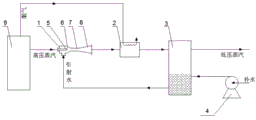
FIG. 2 is a schematic diagram of a steam source system based on a vapor-liquid ejector supercharging flash technology, which adopts a split type heat pipe heater to recover the waste heat of the tail flue gas of a boiler.
FIG. 3 is a schematic diagram of a steam source system based on a vapor-liquid ejector supercharging flash technology, which adopts a heat-conducting oil heater to recover the waste heat of the tail flue gas of a boiler.
FIG. 4 is a schematic diagram of a steam source system based on a vapor-liquid ejector supercharging flash technology, which adopts a flue gas heater to recover the flue gas waste heat at the tail of a boiler.
In the figure: 1. the system comprises a vapor-liquid ejector, 2, a heater, 3, a flash tank, 4, a water replenishing pump, 5, a working nozzle, 6, a suction chamber, 7, a mixing chamber, 8, a diffusion chamber, 9, a steam boiler, 10, a split type heat pipe evaporator, 11 and a heat conduction oil heat collector.
Detailed Description
The technical solution in the implementation of the present invention will be clearly and completely described below with reference to the accompanying drawings of the present invention.
Fig. 1 shows a vapor source system device diagram based on vapor-liquid ejector pressure boost flash technology.
The steam source system provided by the invention comprises a steam-liquid ejector 1, a heater 2, a flash tank 3 and a water replenishing pump 4, wherein all devices are connected by adopting pipelines; the steam-liquid ejector 1 consists of a scaling type working nozzle 5, a suction chamber 6, a mixing chamber 7 and a diffusion chamber 8, a high-pressure steam inlet is connected with an inlet of the working nozzle 5, an injection fluid inlet of the suction chamber 6 is connected with the bottom of the flash tank 3, and an outlet of the diffusion chamber 8 is connected with a cold fluid inlet of the heater 2. When the steam source system operates, high-pressure working steam drives the steam-liquid ejector 1 to generate supersonic jet flow at the outlet of the working nozzle 5, vacuum is formed in the suction chamber 6, low-pressure water in the suction flash tank 3 enters the steam-liquid ejector 1, steam-liquid mixing and condensation boosting are completed in the mixing chamber 7, mixed fluid continues boosting in the diffusion chamber 8, and after the mixed fluid is sent into the heater 2 and heated to be saturated or nearly saturated fluid, the mixed fluid enters the flash tank 3 to be flashed to generate low-pressure saturated steam for a low-pressure steam using process; the low-pressure saturated water which is not flashed is collected at the bottom of the flash tank 3 and is communicated with an injection inlet of the vapor-liquid ejector 1 through an outlet pipe at the bottom of the flash tank 3, so that cyclic pressurization flash evaporation is realized; and the water replenishing pump 4 pumps the low-temperature water to the bottom of the flash tank 3 after boosting the pressure of the low-temperature water, so that the continuous and stable operation of the steam source system is ensured.
FIG. 2 shows a device diagram of a steam source system based on a vapor-liquid ejector supercharging flash technology for recovering the waste heat of the tail flue gas of a boiler by adopting a split type heat pipe heater. When the steam source system is provided with the steam boiler 9, the heater 2 and the split type heat pipe evaporator 10 can form a closed loop, the split type heat pipe evaporator 10 is arranged in a tail flue of the steam boiler 9 to absorb the waste heat of the flue gas, the heat pipe working medium enters the heater 2 after being evaporated to release the latent heat of condensation to heat the pressure boosting water at the outlet of the steam-liquid ejector 1, the heat pipe working medium is condensed into a liquid state and then flows back to the split type heat pipe evaporator 10 to circularly absorb the waste heat of the flue gas.
FIG. 3 shows a device diagram of a steam source system based on a vapor-liquid ejector supercharging flash technology for recovering the waste heat of the tail flue gas of a boiler by adopting a heat-conducting oil heater. When the heater 2 adopts a heat conduction oil heating mode, the heater 2 and the heat conduction oil collector 11 form a closed loop, the heat conduction oil collector 11 is arranged in a tail flue of the steam boiler 9 to absorb the waste heat of the flue gas, the heat conduction oil enters the heater 2 after being heated, the boosting water at the outlet of the steam-liquid ejector 1 is heated, the heat conduction oil flows back to the heat conduction oil collector 11 after being cooled, and the waste heat of the flue gas is circularly absorbed.
FIG. 4 shows a device diagram of a steam source system based on a steam-liquid ejector supercharging flash technology, which adopts a flue gas heater to recover the flue gas waste heat at the tail of a boiler. The heater 2 is directly arranged in a tail flue of the steam boiler 9, and the pressure boosting water at the outlet of the steam-liquid ejector 1 is sent to the heater 2 through a connecting pipeline to absorb the waste heat of the flue gas and then sent to the flash tank 3 through the connecting pipeline to be flashed.

Claims (5)

1. A steam source system based on a steam-liquid ejector supercharging flash technology comprises a steam-liquid ejector (1), a heater (2), a flash tank (3) and a water replenishing pump (4), wherein all devices are connected through pipelines; the vapor-liquid ejector is formed by sequentially connecting a scaling type working nozzle (5), a suction chamber (6), a mixing chamber (7) and a diffusion chamber (8), a high-pressure vapor inlet is connected with an inlet of the working nozzle (5), an injection fluid inlet of the suction chamber (6) is connected with the bottom of a flash tank (3), and an outlet of the diffusion chamber (8) is connected with a cold fluid inlet of a heater (2); the method is characterized in that: the steam source system is driven by high-pressure working steam, supersonic jet flow is generated at an outlet of the working nozzle (5), vacuum is formed in the suction chamber (6), low-pressure water sucked into the flash tank (3) enters the steam-liquid ejector (1), steam-liquid mixing and condensation boosting are completed in the mixing chamber (7), mixed fluid continues boosting in the diffusion chamber (8), the mixed fluid is sent into the heater (2) to be heated into saturated or nearly saturated fluid, and the mixed fluid enters the flash tank (3) to be flashed, so that low-pressure saturated steam is generated; the low-pressure saturated water which is not flashed is collected at the bottom of the flash tank (3) and is communicated with an injection inlet of the vapor-liquid ejector (1) through an outlet pipe at the bottom of the flash tank (3), so that cyclic pressurization flash evaporation is realized; and the water replenishing pump (4) is used for delivering the low-temperature water to the bottom of the flash tank (3) so as to ensure the continuous and stable operation of the steam source system.
2. The vapor source system based on the vapor-liquid ejector supercharging flash technology according to claim 1, characterized in that: the heater (2) in the steam source system adopts the waste heat of the tail flue gas of the steam boiler (9) as a heating source, and the specific form of the heater is a split type heat pipe heater, a heat conducting oil heater or a flue gas heater.
3. The vapor source system based on the vapor-liquid ejector supercharging flash technology according to the claims 1 and 2, characterized in that: when the heater (2) in the steam source system is in the form of a split type heat pipe heater, the heater (2) and the split type heat pipe evaporator (10) form a closed loop, the split type heat pipe evaporator (10) is arranged in a flue at the tail of the steam boiler (9) to absorb the waste heat of flue gas, and the heater (2) of the steam source system releases heat by condensing a heat pipe working medium.
4. The vapor source system based on the vapor-liquid ejector supercharging flash technology according to the claims 1 and 2, characterized in that: when the heater (2) in the steam source system is a heat-conducting oil heater, the heater (2) and the heat-conducting oil collector (11) form a closed loop, the heat-conducting oil collector (11) is arranged in a flue at the tail of the steam boiler (9) to absorb the waste heat of flue gas, and the heater (2) takes heat-conducting oil as a heating source.
5. The vapor source system based on the vapor-liquid ejector supercharging flash technology according to the claims 1 and 2, characterized in that: when the heater (2) in the steam source system is in the form of a flue gas heater, the heater (2) is arranged in a flue at the tail part of the steam boiler (9) to directly absorb the waste heat of the flue gas.
CN202110785694.4A 2021-07-12 2021-07-12 Vapor source system based on vapor-liquid ejector supercharging flash evaporation technology Pending CN113404474A (en)

Priority Applications (3)

Application Number Priority Date Filing Date Title
CN202110785694.4A CN113404474A (en) 2021-07-12 2021-07-12 Vapor source system based on vapor-liquid ejector supercharging flash evaporation technology
PCT/CN2021/113134 WO2023284061A1 (en) 2021-07-12 2021-08-18 Steam source system based on steam-liquid ejector pressurization and flashing technology
US17/946,131 US12228280B2 (en) 2021-07-12 2022-09-16 Vapor source system based on vapor-liquid ejector supercharging combined with flash vaporization technology

Applications Claiming Priority (1)

Application Number Priority Date Filing Date Title
CN202110785694.4A CN113404474A (en) 2021-07-12 2021-07-12 Vapor source system based on vapor-liquid ejector supercharging flash evaporation technology

Publications (1)

Publication Number Publication Date
CN113404474A true CN113404474A (en) 2021-09-17

Family

ID=77685926

Family Applications (1)

Application Number Title Priority Date Filing Date
CN202110785694.4A Pending CN113404474A (en) 2021-07-12 2021-07-12 Vapor source system based on vapor-liquid ejector supercharging flash evaporation technology

Country Status (2)

Country Link
CN (1) CN113404474A (en)
WO (1) WO2023284061A1 (en)

Cited By (2)

* Cited by examiner, † Cited by third party
Publication number Priority date Publication date Assignee Title
CN114321866A (en) * 2022-01-10 2022-04-12 浙江诚信医化设备有限公司 A negative pressure steam temperature control device
CN114659081A (en) * 2022-04-19 2022-06-24 大连理工大学 A shower-excited heat exchange sewage circulating flash steam generation system

Families Citing this family (4)

* Cited by examiner, † Cited by third party
Publication number Priority date Publication date Assignee Title
CN116481071A (en) * 2023-04-26 2023-07-25 浙江墨创环保科技工程有限公司 A jet type continuous drainage waste heat recovery system and method
CN116839009A (en) * 2023-08-22 2023-10-03 山蓝(山东)节能环保科技有限公司 A device and method for preparing steam using waste heat
CN118324225A (en) * 2024-04-19 2024-07-12 清华大学深圳国际研究生院 Low-grade waste heat driven high-salinity wastewater low-temperature spray flash zero-emission treatment system
CN119499682B (en) * 2024-10-31 2025-09-23 南通星球石墨股份有限公司 A hydrogen chloride synthesis system with high by-product 1.0MpaG steam

Citations (6)

* Cited by examiner, † Cited by third party
Publication number Priority date Publication date Assignee Title
US20010020649A1 (en) * 2000-03-10 2001-09-13 Compagnie Generale Des Matieres Nucleaires Vapor -liquid ejector with a removable nozzle
CA2665751A1 (en) * 2008-05-12 2009-11-12 Maoz Betser-Zilevitch Integrated steam generation process for enhanced oil recovery
CN106194298A (en) * 2016-08-30 2016-12-07 广东工业大学 A kind of gas-liquid injection formula ORC system
CN206146160U (en) * 2016-08-31 2017-05-03 河北新大东纺织有限公司 Steam -jet ejector heating system
CN206387141U (en) * 2016-11-25 2017-08-08 天津大学 A kind of combined twin-stage steam heat pump system
CN109083705A (en) * 2018-07-03 2018-12-25 广东工业大学 Change component multiple pressure with injector evaporates non-azeotropic working medium Rankine cycle system

Family Cites Families (7)

* Cited by examiner, † Cited by third party
Publication number Priority date Publication date Assignee Title
JP2007190249A (en) * 2006-01-20 2007-08-02 Taiyo Bensen Kk Steam circulation system of clothes cleaning plant
KR100774546B1 (en) * 2006-11-13 2007-11-08 두산중공업 주식회사 Seawater desalination system using discharged water from steam recovery steam generator
CN104296544B (en) * 2014-10-13 2016-07-06 中信重工机械股份有限公司 A kind of low-temperature cogeneration flash system
CN206861916U (en) * 2017-05-16 2018-01-09 北京清大天工能源技术研究所有限公司 A kind of HEAT PUMP BASED ON EJECTING PRINCIPLE residual heat resources retracting device of vegetable protein flash-off steam
CN108167040B (en) * 2017-11-17 2020-05-15 昆明理工大学 A dual-pressure expansion organic Rankine cycle recovery medium and low temperature waste heat power generation system
CN108343941A (en) * 2017-12-27 2018-07-31 麻克栋 A kind of self-loopa steam heating method
CN108411052A (en) * 2018-02-27 2018-08-17 首钢京唐钢铁联合有限责任公司 Low-grade waste heat recovery system

Patent Citations (6)

* Cited by examiner, † Cited by third party
Publication number Priority date Publication date Assignee Title
US20010020649A1 (en) * 2000-03-10 2001-09-13 Compagnie Generale Des Matieres Nucleaires Vapor -liquid ejector with a removable nozzle
CA2665751A1 (en) * 2008-05-12 2009-11-12 Maoz Betser-Zilevitch Integrated steam generation process for enhanced oil recovery
CN106194298A (en) * 2016-08-30 2016-12-07 广东工业大学 A kind of gas-liquid injection formula ORC system
CN206146160U (en) * 2016-08-31 2017-05-03 河北新大东纺织有限公司 Steam -jet ejector heating system
CN206387141U (en) * 2016-11-25 2017-08-08 天津大学 A kind of combined twin-stage steam heat pump system
CN109083705A (en) * 2018-07-03 2018-12-25 广东工业大学 Change component multiple pressure with injector evaporates non-azeotropic working medium Rankine cycle system

Cited By (3)

* Cited by examiner, † Cited by third party
Publication number Priority date Publication date Assignee Title
CN114321866A (en) * 2022-01-10 2022-04-12 浙江诚信医化设备有限公司 A negative pressure steam temperature control device
CN114659081A (en) * 2022-04-19 2022-06-24 大连理工大学 A shower-excited heat exchange sewage circulating flash steam generation system
CN114659081B (en) * 2022-04-19 2024-11-15 大连理工大学 A flash steam generation system for sewage circulation with shower heat exchange

Also Published As

Publication number Publication date
WO2023284061A1 (en) 2023-01-19

Similar Documents

Publication Publication Date Title
CN113404474A (en) Vapor source system based on vapor-liquid ejector supercharging flash evaporation technology
CN205858491U (en) The water combined power and cooling distributed energy system of promotion is combined based on combustion gas ORC
CN111912135B (en) Two-stage ejector combined cooling and power hybrid circulation system
CN201301785Y (en) High-efficiency ocean thermal energy power-generation device
CN103161607A (en) Combined power generating system based on waste-heat utilization of combustion motor
CN108643981B (en) A low-grade heat source-driven non-azeotropic mixed heat and power cogeneration system and method
CN103112985B (en) Multi-stage flash distillation seawater desalination system of low-temperature multi-effect steamer vapor compression distillation
CN101737282A (en) High-efficiency hybrid ocean temperature difference power generating system
CN102434235A (en) Kalina cycle power generation system using ejector
CN202869079U (en) A device for heating condensed water by recovering the waste heat of circulating cooling water in a power plant by means of a jet heat pump
CN106766342B (en) System for recovering ammonia steam waste heat at top of ammonia still tower by using lithium bromide absorption heat pump
CN107218094A (en) A kind of multiple pressure flashes the device of organic Rankine bottoming cycle cogeneration
CN204267009U (en) The straight producing steam heavy oil thermal recovery system of solar energy
CN102344178A (en) Thermal steam compression, evaporation and desalination system with function of steam reheating and method
CN201620052U (en) Solar seawater desalination device based on ultrasonic wave and throttling technology
CN106940100B (en) The complicated utilization system of low-temperature heat source
CN114992070B (en) Combined cooling and power system driven by ocean energy and solar energy waste heat and working method
US12228280B2 (en) Vapor source system based on vapor-liquid ejector supercharging combined with flash vaporization technology
CN209875221U (en) System for improving power generation capacity of medium-low temperature heat source by adopting injection pump and separator
CN112160882A (en) Ocean temperature difference energy-based low-grade heat source driven water-cooling poly-generation system and method
CN205424891U (en) Heat recovery unit of oxygen -eliminating device exhaust steam among boiler vapour turbine system
CN216694064U (en) A heat pump system for producing fresh water
CN203532054U (en) Combined circulation system of microturbine based on renewable energy sources
CN203257488U (en) Water or liquid medium steam non-condensing cycle generation system
CN203452859U (en) Single-screw expander medium and low temperature geothermal power generation system based on lubricating oil cycle loop

Legal Events

Date Code Title Description
PB01 Publication
PB01 Publication
SE01 Entry into force of request for substantive examination