CN113390551A - System and method for monitoring wheel-rail contact force - Google Patents
System and method for monitoring wheel-rail contact force Download PDFInfo
- Publication number
- CN113390551A CN113390551A CN202110250063.2A CN202110250063A CN113390551A CN 113390551 A CN113390551 A CN 113390551A CN 202110250063 A CN202110250063 A CN 202110250063A CN 113390551 A CN113390551 A CN 113390551A
- Authority
- CN
- China
- Prior art keywords
- wheel
- rail
- bogie
- acceleration
- rail contact
- Prior art date
- Legal status (The legal status is an assumption and is not a legal conclusion. Google has not performed a legal analysis and makes no representation as to the accuracy of the status listed.)
- Pending
Links
Images


Classifications
-
- B—PERFORMING OPERATIONS; TRANSPORTING
- B61—RAILWAYS
- B61K—AUXILIARY EQUIPMENT SPECIALLY ADAPTED FOR RAILWAYS, NOT OTHERWISE PROVIDED FOR
- B61K9/00—Railway vehicle profile gauges; Detecting or indicating overheating of components; Apparatus on locomotives or cars to indicate bad track sections; General design of track recording vehicles
- B61K9/08—Measuring installations for surveying permanent way
-
- G—PHYSICS
- G01—MEASURING; TESTING
- G01L—MEASURING FORCE, STRESS, TORQUE, WORK, MECHANICAL POWER, MECHANICAL EFFICIENCY, OR FLUID PRESSURE
- G01L5/00—Apparatus for, or methods of, measuring force, work, mechanical power, or torque, specially adapted for specific purposes
- G01L5/20—Apparatus for, or methods of, measuring force, work, mechanical power, or torque, specially adapted for specific purposes for measuring wheel side-thrust
-
- B—PERFORMING OPERATIONS; TRANSPORTING
- B61—RAILWAYS
- B61L—GUIDING RAILWAY TRAFFIC; ENSURING THE SAFETY OF RAILWAY TRAFFIC
- B61L15/00—Indicators provided on the vehicle or train for signalling purposes
- B61L15/0072—On-board train data handling
-
- B—PERFORMING OPERATIONS; TRANSPORTING
- B61—RAILWAYS
- B61L—GUIDING RAILWAY TRAFFIC; ENSURING THE SAFETY OF RAILWAY TRAFFIC
- B61L15/00—Indicators provided on the vehicle or train for signalling purposes
- B61L15/0081—On-board diagnosis or maintenance
-
- B—PERFORMING OPERATIONS; TRANSPORTING
- B61—RAILWAYS
- B61L—GUIDING RAILWAY TRAFFIC; ENSURING THE SAFETY OF RAILWAY TRAFFIC
- B61L23/00—Control, warning or like safety means along the route or between vehicles or trains
- B61L23/04—Control, warning or like safety means along the route or between vehicles or trains for monitoring the mechanical state of the route
- B61L23/042—Track changes detection
-
- B—PERFORMING OPERATIONS; TRANSPORTING
- B61—RAILWAYS
- B61L—GUIDING RAILWAY TRAFFIC; ENSURING THE SAFETY OF RAILWAY TRAFFIC
- B61L27/00—Central railway traffic control systems; Trackside control; Communication systems specially adapted therefor
- B61L27/60—Testing or simulation
-
- G—PHYSICS
- G01—MEASURING; TESTING
- G01L—MEASURING FORCE, STRESS, TORQUE, WORK, MECHANICAL POWER, MECHANICAL EFFICIENCY, OR FLUID PRESSURE
- G01L5/00—Apparatus for, or methods of, measuring force, work, mechanical power, or torque, specially adapted for specific purposes
-
- G—PHYSICS
- G01—MEASURING; TESTING
- G01M—TESTING STATIC OR DYNAMIC BALANCE OF MACHINES OR STRUCTURES; TESTING OF STRUCTURES OR APPARATUS, NOT OTHERWISE PROVIDED FOR
- G01M17/00—Testing of vehicles
- G01M17/08—Railway vehicles
- G01M17/10—Suspensions, axles or wheels
Landscapes
- Engineering & Computer Science (AREA)
- Mechanical Engineering (AREA)
- Physics & Mathematics (AREA)
- General Physics & Mathematics (AREA)
- Health & Medical Sciences (AREA)
- Biomedical Technology (AREA)
- General Health & Medical Sciences (AREA)
- Testing Of Devices, Machine Parts, Or Other Structures Thereof (AREA)
- Electric Propulsion And Braking For Vehicles (AREA)
- Vehicle Body Suspensions (AREA)
Abstract
A system for monitoring wheel-rail contact forces is disclosed, the system comprising a measurement unit for measuring vertical acceleration of a wheel connected to a bogie, wherein the wheel is configured to travel on a track, wherein the system comprises a calculation unit for simulating a wheel-rail interaction using the measured vertical acceleration and for calculating a wheel-rail contact force based on the simulated wheel-rail interaction.
Description
Technical Field
The invention relates to a system for monitoring a wheel-rail contact force according to claim 1. The invention also relates to a method for monitoring a wheel-rail contact force according to claim 7.
Background
In the field of rail vehicles, it is beneficial to know the contact force between the wheels of a bogie of a rail vehicle (such as a train) and the rail in order to understand the performance of the vehicle and its components. Vehicle maintainers and designers can use such information to improve the track and/or vehicle. Furthermore, it is important for the manufacturer of the axle box bearing to know whether the calculated load value corresponds to the actual value.
In known systems, the interaction between the track and the wheels is monitored by using dedicated instrumented wheelsets (/ wheelsets) which are only temporarily, but not permanently installed. In order to monitor the interaction between the rail and the wheelset, it is necessary to remove the wheelset, install all the meters, take measurements over a period of time, and then remove all the items.
Disclosure of Invention
It is therefore an object of the present invention to provide a simplified method for monitoring the force at a wheel rail contact.
This object is solved by a system for monitoring a wheel-rail contact force according to claim 1 and a method for monitoring a wheel-rail contact force according to claim 7.
A system for monitoring wheel-rail contact forces comprises a measurement unit for measuring vertical acceleration of a wheel connected to a bogie (bogie). A bogie is a component of a rail vehicle that travels on rails. The bogie may comprise, for example, four wheels, wherein an axle box (/ axlebox) on the bogie supports one wheel of the bogie.
The system further comprises a calculation unit for simulating a wheel-rail interaction using the measured vertical acceleration. Furthermore, the calculation unit is configured to calculate a wheel-rail contact force based on the simulated wheel-rail interaction. On the basis of this simulation, there is no need to measure the speed (speed) or velocity (velocity) of the bogie, since the calculation of the wheel-rail contact force is based only on a simulation using measured vertical acceleration. Using such measurements, there is no need to install a temporary instrumented wheel set, since the required measuring elements can be permanently installed at the wheels of the bogie.
According to an embodiment, the measurement unit is adapted to measure (adapted to) the acceleration of the wheel by measuring the acceleration of an axle box (axle box) connected to the wheel. For example, the measurement unit may be adapted to measure one acceleration signal per axle box, e.g. using one acceleration sensor per axle box. Thus, the vertical acceleration is measured at the axle boxes on the bogie, which axle boxes support the wheels travelling on the rail and are thus affected by undulations (undulations) or corrugations (corrugations) in the surface of the rail.
The calculation unit may also be adapted to (adapted to) convert the vertical acceleration of the wheel into a vertical velocity of the wheel. Although, in contrast to known systems, there is therefore no need to measure velocity or speed (speed or velocity), the vertical acceleration can be used directly for further processing and determining the contact force. It should be noted that throughout this specification, the terms "speed" and "rate" are synonymous.
A suitable model of the bogie (e.g. a quarter bogie model) may be used to simulate the dynamic behaviour of the bogie. In particular, the calculation unit may be adapted to simulate a two-mass model of the quarter bogie. The known mass parameters, stiffness and damping parameters of the system, and the measured acceleration signal can then be used to solve the corresponding equation for the motion of the bogie rail system.
Therefore, the vertical acceleration signal (acc1) is used directly to solve the equation of motion associated with the model. Further, the signal is subjected to only one integration process to obtain a vertical velocity signal (vel1), which is also used as an input to solve the equation. This may provide the following benefits: the calculated vertical profile signal z therefore contains minimal noise and has a high accuracy.
The two-mass model (2-mass model) may be based on the sprung mass of the bogie (spring mass), the primary suspension parameters, the unsprung mass of the wheels, and the rail contact stiffness. Here, it is assumed that the axle box forming part of the unsprung mass of the bogie is connected to the second mass, which is the sprung mass, via the primary suspension.
Hereinafter, examples of such two-mass models will be described. It should be noted that the two quality models described are merely exemplary and may be adjusted as necessary.
The equation for the motion of the quarter bogie model in the time domain is as follows:


the accelerometer measures the vertical acceleration of the unsprung mass m1, which means that the vertical acceleration signal acc1 is equal to Thus, the vertical speed signal vel1 obtained from acc1 is equal to
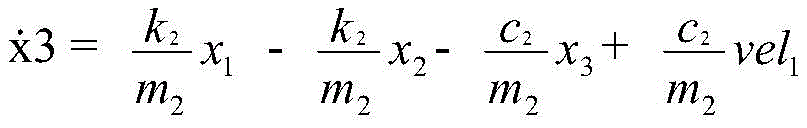
 Other known parameters are the masses m1 and m2(kg), the spring coefficient k2(N/m) and the damping coefficient c2 of the main suspension, and the spring coefficient k1(N/m) and the damping coefficient c1 of the wheel contact stiffness.
First, equation [1] is solved using the vertical velocity signal vel 1.
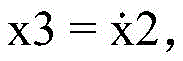
Suitably, the state variables x1, x2, and x3 are defined such that:
x 1-y 1 (vertical displacement of m 1), push out
x2 ═ y2 (vertical displacement of m 2).
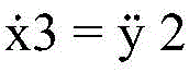
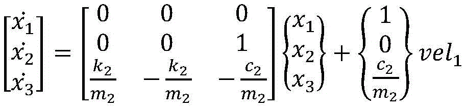
Thus, equation [1] can be expressed in the form of a state variable as:

thereby to obtain
Using the known stiffness and damping matrices, equation [1] can be solved as follows:

to obtain the vertical displacement y1 of unsprung mass m1, the vertical displacement y2 of sprung mass m2 and the vertical velocity of sprung mass m2
Equation [2] can now be solved for function z:

once z is obtained, this value can be used to calculate the force at the wheel rail contact.
F1=-k1(desp1-z)

Using the above-described system and method, an inexpensive wheel-rail contact force condition monitoring method can be provided that can be integrated into existing condition monitoring systems and that employs acceleration measurements in the axle box. Such monitoring of the wheel-rail contact force may be used to determine potentially harmful undulations (corrugations) that may require repair or maintenance. This ripple determination can be forwarded (forwarded) to the operator of the rail vehicle or rail system for the corresponding measurement.
Another aspect of the invention relates to a method for monitoring wheel-rail contact force. The method comprises the following steps: measuring vertical acceleration of a wheel connected to the bogie; the measured vertical acceleration is used to simulate wheel-rail interaction, and wheel-rail contact force is calculated based on the simulated wheel-rail interaction.
Another aspect of the invention relates to a computer program product comprising computer program code adapted to prompt a control unit (e.g. a computer) and/or a computer of the above-mentioned monitoring system to perform the above-mentioned steps.
The computer program product may be provided as a storage means, such as a memory card, a USB stick, a CD-Rom, a DVD, and/or may be a file that can be downloaded from a server in the network, in particular a remote server. The network may be a wireless communication network for communicating files with the computer program product.
Further preferred embodiments are defined in the dependent claims as well as in the description and the drawings. Thus, elements described or illustrated in combination with other elements may exist alone or in combination with other elements without departing from the scope of protection.
In the following, preferred embodiments of the invention are described with respect to the accompanying drawings, which are only exemplary and not intended to limit the scope of protection. The scope of protection is only limited by the appended claims.
Drawings
The figures show:
FIG. 1: a part of the bogie (bogie) is arranged in a perspective view on the track.
FIG. 2: a schematic block diagram of a system for monitoring the wheel-rail contact force of the truck of fig. 1; and
FIG. 3: schematic representation of a mass model used in the system of fig. 2.
Reference numerals
1 bogie
2 wheel
4 track
6 axle box
8 axle (/ axle) (axle)
10 system
12 acceleration sensor
16 measuring cell
18 calculation unit
20 simulation model
22 sprung mass m2
24 unsprung mass m1
26 input
28 output
F1 wheel-rail contact force
k2, c2 Primary suspension parameters
Detailed Description
In the following, identical or similar functional elements are indicated with identical reference numerals.
Fig. 1 shows a part of a bogie 1, which bogie 1 comprises four wheels 2 on a track 4. The bogie 1 is a bogie of a railway vehicle running on a rail 4. The wheels 2 are supported by axle boxes (axle box)6, the axle boxes 6 being coupled with axles (axle) 8.
To monitor the wheel-rail contact force, the system 10 (shown in fig. 2) may be used to measure the vertical acceleration of the wheel 2. Thus, one acceleration sensor 12 is arranged at each wheel 2.
Fig. 2 shows a schematic block diagram of a system 10 for monitoring wheel-rail contact force. The system 10 includes a measurement unit 16, and the measurement unit 16 may include a sensor 12 as shown in FIG. 1. The sensors may be, for example, one acceleration sensor 12 per wheel 2.
The system 10 also includes a calculation unit 18. The calculation unit 18 may receive the measured vertical acceleration as an input signal 26 and may use the measured vertical acceleration to simulate a wheel-rail interaction. Furthermore, the calculation unit 18 may calculate the wheel-rail contact force based on the simulated wheel-rail interaction.
To simulate wheel-rail interactions, the calculation unit 18 may use a simulation model, as shown in fig. 3.
The simulation model 20 shown in fig. 3 uses a sprung mass 22 (i.e., the sprung mass of the bogie 1), a primary suspension parameter k2And c2Unsprung mass 24 (i.e.The mass of the wheelset) and the wheel-rail contact stiffness. Furthermore, the simulation model uses the measured vertical acceleration. Based on these parameters, the simulation model 20 simulates the behavior of the bogie 1. The simulation model 20 may be used to determine the wheel-rail contact force F1. For this purpose, only one measured input parameter 26, namely the vertical acceleration, is required.
In a first step, the calculation unit 18 converts the measured vertical acceleration of the wheel 2 into a vertical velocity of the wheel 2. The simulation model of fig. 3 thus uses the vertical speed of the wheel 2 (based on the measured acceleration) as input.
Based on the two-mass model and the dynamic parameters of the bogie 1 and the measured signals, the calculation unit 18 calculates a wheel-rail contact force F1 based on the simulated wheel-rail interaction, which wheel-rail contact force F1 can be forwarded for further processing as output 28. This information can then be used to monitor wheel rail contact forces and determine defects on the rail or wheel.
Using the above-described system and method, inexpensive wheel-rail contact force condition monitoring may be provided because only one parameter (i.e., acceleration) needs to be measured. This monitored force at the wheel rail contact can be used to determine a potentially harmful ripple (harmafull corrugation) that may require repair (/ repair) or maintenance.
Claims (7)
Applications Claiming Priority (2)
| Application Number | Priority Date | Filing Date | Title |
|---|---|---|---|
| EP20380012.3 | 2020-03-12 | ||
| EP20380012 | 2020-03-12 |
Publications (1)
| Publication Number | Publication Date |
|---|---|
| CN113390551A true CN113390551A (en) | 2021-09-14 |
Family
ID=71143674
Family Applications (1)
| Application Number | Title | Priority Date | Filing Date |
|---|---|---|---|
| CN202110250063.2A Pending CN113390551A (en) | 2020-03-12 | 2021-03-08 | System and method for monitoring wheel-rail contact force |
Country Status (4)
| Country | Link |
|---|---|
| US (1) | US20210284206A1 (en) |
| CN (1) | CN113390551A (en) |
| DE (1) | DE102020209184A1 (en) |
| FR (1) | FR3108173B1 (en) |
Families Citing this family (1)
| Publication number | Priority date | Publication date | Assignee | Title |
|---|---|---|---|---|
| DE102022107484A1 (en) | 2022-03-30 | 2023-10-05 | Schenck Process Europe Gmbh | Method and device for approximating an acceleration signal curve recorded when a rail-bound vehicle travels over a measuring section to the characteristic features of a force signal curve corresponding thereto |
Citations (10)
| Publication number | Priority date | Publication date | Assignee | Title |
|---|---|---|---|---|
| AU2004200527A1 (en) * | 2003-02-18 | 2004-09-02 | Central Queensland University | A Vehicle Dynamics System |
| CN104006978A (en) * | 2014-05-29 | 2014-08-27 | 西南交通大学 | Method for indirectly measuring acting force between railway vehicle wheel tracks |
| CN104878668A (en) * | 2015-05-29 | 2015-09-02 | 南京理工大学 | Rail vertical irregularity estimation method and system based on extended Kalman filtering |
| CN105000033A (en) * | 2015-08-13 | 2015-10-28 | 哈尔滨工业大学 | Inspection and evaluation system for track geometric irregularity |
| CN106096096A (en) * | 2016-06-01 | 2016-11-09 | 北京交通大学 | Train suspension system failure analysis methods based on MPCA and system |
| CN107200040A (en) * | 2016-03-17 | 2017-09-26 | 斯凯孚公司 | For the method and system for the vertically profiling for determining raceway surface |
| CN108536930A (en) * | 2018-03-26 | 2018-09-14 | 中国铁路总公司 | A kind of holography wheel rail force discrimination method and system |
| CN109086525A (en) * | 2018-08-03 | 2018-12-25 | 西南交通大学 | Method is determined based on the optimal trajectory structural shape of overhead box-beam structure noise prediction |
| CN109918753A (en) * | 2019-02-26 | 2019-06-21 | 北京市劳动保护科学研究所 | Method and system for determining wheel-rail force of a train |
| CN109916643A (en) * | 2019-04-08 | 2019-06-21 | 西南交通大学 | Research test bench and test method for wheel-rail force load identification based on track vibration |
Family Cites Families (3)
| Publication number | Priority date | Publication date | Assignee | Title |
|---|---|---|---|---|
| GB9911170D0 (en) * | 1999-05-14 | 1999-07-14 | Aea Technology Plc | Track monitoring equipment |
| WO2006130908A1 (en) * | 2005-06-08 | 2006-12-14 | Qr Limited | Estimation of wheel rail interaction forces |
| JP6992726B2 (en) * | 2018-10-26 | 2022-01-13 | 日本電気株式会社 | Driving support device, driving support method, program |
-
2020
- 2020-07-22 DE DE102020209184.6A patent/DE102020209184A1/en active Pending
-
2021
- 2021-01-26 US US17/158,410 patent/US20210284206A1/en active Pending
- 2021-02-19 FR FR2101640A patent/FR3108173B1/en active Active
- 2021-03-08 CN CN202110250063.2A patent/CN113390551A/en active Pending
Patent Citations (10)
| Publication number | Priority date | Publication date | Assignee | Title |
|---|---|---|---|---|
| AU2004200527A1 (en) * | 2003-02-18 | 2004-09-02 | Central Queensland University | A Vehicle Dynamics System |
| CN104006978A (en) * | 2014-05-29 | 2014-08-27 | 西南交通大学 | Method for indirectly measuring acting force between railway vehicle wheel tracks |
| CN104878668A (en) * | 2015-05-29 | 2015-09-02 | 南京理工大学 | Rail vertical irregularity estimation method and system based on extended Kalman filtering |
| CN105000033A (en) * | 2015-08-13 | 2015-10-28 | 哈尔滨工业大学 | Inspection and evaluation system for track geometric irregularity |
| CN107200040A (en) * | 2016-03-17 | 2017-09-26 | 斯凯孚公司 | For the method and system for the vertically profiling for determining raceway surface |
| CN106096096A (en) * | 2016-06-01 | 2016-11-09 | 北京交通大学 | Train suspension system failure analysis methods based on MPCA and system |
| CN108536930A (en) * | 2018-03-26 | 2018-09-14 | 中国铁路总公司 | A kind of holography wheel rail force discrimination method and system |
| CN109086525A (en) * | 2018-08-03 | 2018-12-25 | 西南交通大学 | Method is determined based on the optimal trajectory structural shape of overhead box-beam structure noise prediction |
| CN109918753A (en) * | 2019-02-26 | 2019-06-21 | 北京市劳动保护科学研究所 | Method and system for determining wheel-rail force of a train |
| CN109916643A (en) * | 2019-04-08 | 2019-06-21 | 西南交通大学 | Research test bench and test method for wheel-rail force load identification based on track vibration |
Also Published As
| Publication number | Publication date |
|---|---|
| DE102020209184A1 (en) | 2021-09-16 |
| FR3108173A1 (en) | 2021-09-17 |
| FR3108173B1 (en) | 2023-02-17 |
| US20210284206A1 (en) | 2021-09-16 |
Similar Documents
| Publication | Publication Date | Title |
|---|---|---|
| CN104032629B (en) | A kind of vertical track long wave irregularity on-line monitoring method and system | |
| CN108562446B (en) | Wheel polygon detection method and terminal equipment based on time-frequency domain characteristics of axle box vibration | |
| Bhardawaj et al. | Ride analysis of track-vehicle-human body interaction subjected to random excitation | |
| Muñoz et al. | Estimation of lateral track irregularity through Kalman filtering techniques | |
| Yang et al. | Bridge surface roughness identified from the displacement influence lines of the contact points by two connected vehicles | |
| Szafrański | A dynamic vehicle-bridge model based on the modal identification results of an existing EN57 train and bridge spans with non-ballasted tracks | |
| CN104878668A (en) | Rail vertical irregularity estimation method and system based on extended Kalman filtering | |
| CN107200040B (en) | Method and system for determining the vertical profile of a track surface | |
| CN102874277B (en) | Estimation of wheel rail interaction forces | |
| CN109766635B (en) | Optimized layout method for state perception sensor of mechanical part of locomotive | |
| CN111256986B (en) | Variable-gauge bogie axle durability test method | |
| Sayyaadi et al. | A new model in rail–vehicles dynamics considering nonlinear suspension components behavior | |
| CN111444574B (en) | Sensor layout optimization method based on dynamics analysis | |
| Bosso et al. | Scale testing theory and approaches | |
| CN113390551A (en) | System and method for monitoring wheel-rail contact force | |
| Steišūnas et al. | Estimation of ambient temperature impact on vertical dynamic behaviour of passenger rail vehicle with damaged wheels | |
| Tokunaga | Displacement response waveform restoration of simply supported bridge during train passage using measured acceleration integration based on linear vibration theory | |
| Bosso et al. | Simulation of narrow gauge railway vehicles and experimental validation by mean of scaled tests on roller rig | |
| Singh et al. | Estimating coach-suspension parameters through stop braking: analytical modeling and validation | |
| Bizimungu et al. | Vibration responses of the railcar under rail irregularities: case of Addis Ababa light rail transit | |
| Ágh | Connection between track geometry quality and dynamic vehicle response at various speeds | |
| WO2023199369A1 (en) | Life evaluation device and method | |
| Bosso et al. | Dynamic identification of a 1: 5 scaled railway bogie on roller rig | |
| Ignesti et al. | Development of an innovative weigh in motion system for railway vehicles | |
| Amerio et al. | Damage detection in railway bridges by means of train on-board sensors: A perspective option |
Legal Events
| Date | Code | Title | Description |
|---|---|---|---|
| PB01 | Publication | ||
| PB01 | Publication | ||
| SE01 | Entry into force of request for substantive examination | ||
| SE01 | Entry into force of request for substantive examination |