Disclosure of Invention
Therefore, the invention provides a technical scheme which can timely and accurately predict the parallel line behavior of the target vehicle and further correspondingly adjust the driving state of the current vehicle in advance, and aims to improve the driving safety of the current vehicle.
According to a first aspect of the present invention, there is provided a vehicle assist system for calculating a merging possibility of a target vehicle for a current vehicle based on an artificial intelligence model, the vehicle assist system comprising:
a data acquisition unit configured to detect a relative position of the target vehicle with respect to the current vehicle, start acquiring data related to the target vehicle in a plurality of consecutive preset time slots when it is detected that the target vehicle appears at a first preset angle with respect to the current vehicle on a rear side of the current vehicle until the data acquisition unit detects that the target vehicle appears at a second preset angle with respect to the current vehicle on a side of the current vehicle, wherein the acquired data includes at least an acceleration of the target vehicle, a traveling direction of the target vehicle, and a distance between the target vehicle and the current vehicle;
a data processing unit configured to generate a matrix set by using data collected in each preset time slot, and output the matrix set at the end of each preset time slot, wherein the matrix set includes at least three matrix layers respectively related to a corresponding one type of data in the collected data; and
a calculation unit configured to calculate a merging possibility of the target vehicle by inputting each of the outputted matrix sets to an artificial intelligence model.
In one embodiment, the artificial intelligence model can be a convolutional neural network model, preferably a LeNet-5 architecture.
In one embodiment, the first preset angle may be selected between 45 degrees and 60 degrees of the target vehicle located at the rear side of the current vehicle; and/or the second preset angle may be selected from a range from 0 degrees to 10 degrees or less of the target vehicle located on the rear side of the current vehicle, a range from 0 degrees when the target vehicle is parallel to the current vehicle, and a range from 0 degrees to 45 degrees or less of the target vehicle located on the front side of the current vehicle.
In one embodiment, the calculating the merging possibility of the target vehicle may include: and respectively calculating the merging possibility of the target vehicle represented by each matrix set by using an artificial intelligence model, and then calculating the total merging possibility of the target vehicle by multiplying each merging possibility by a corresponding preset weighted value and summing.
According to a second aspect of the present invention, there is provided a vehicle including the vehicle assistance system described in any one of the above embodiments.
According to a third aspect of the present invention, there is provided a vehicle assist method for calculating a merging possibility of a target vehicle for a current vehicle based on an artificial intelligence model, the vehicle assist method comprising the steps of:
a data acquisition step: detecting a relative position of the target vehicle with respect to the current vehicle, starting to collect data related to the target vehicle in a plurality of consecutive preset time slots when it is detected that the target vehicle appears at a first preset angle with respect to the current vehicle on a rear side of the current vehicle until it is detected that the target vehicle appears at a second preset angle with respect to the current vehicle on a side of the current vehicle, wherein the collected data includes at least an acceleration of the target vehicle, a traveling direction of the target vehicle, and a distance between the target vehicle and the current vehicle;
and (3) data processing: generating a matrix set by using data collected in each preset time slot, and outputting the matrix set at the end of each preset time slot, wherein the matrix set comprises at least three matrix layers which are respectively related to corresponding one type of data in the collected data; and
a calculation step: calculating a merging probability of the target vehicle by inputting each matrix set outputted to an artificial intelligence model.
In one embodiment, the artificial intelligence model can be a convolutional neural network model, preferably a LeNet-5 architecture.
In one embodiment, the first preset angle may be selected between 45 degrees and 60 degrees of the target vehicle located at the rear side of the current vehicle; and/or the second preset angle may be selected from a range from 0 degrees to 10 degrees or less of the target vehicle located on the rear side of the current vehicle, a range from 0 degrees when the target vehicle is parallel to the current vehicle, and a range from 0 degrees to 45 degrees or less of the target vehicle located on the front side of the current vehicle.
In one embodiment, the calculating the merging possibility of the target vehicle may include: and respectively calculating the merging possibility of the target vehicle represented by each matrix set by using an artificial intelligence model, and then calculating the total merging possibility of the target vehicle by multiplying each merging possibility by a corresponding preset weighted value and summing.
According to a fourth aspect of the present invention, there is provided a computer-readable storage medium having stored thereon a computer program which, when executed by a processor, implements the vehicle assist method described in any one of the above embodiments.
By using the technical scheme of the invention, the possibility of merging can be efficiently and accurately judged by collecting the relevant driving data of the target vehicles around the current vehicle in a set time period. Specifically, from the detection of the occurrence of a target vehicle at a first preset angle on the rear side of the current vehicle until the detection of the occurrence of the target vehicle parallel to the current vehicle or the occurrence of the target vehicle at a second preset angle on the front side of the current vehicle, data related to the target vehicle are collected in a plurality of consecutive preset time slots, the collected data are processed into at least three matrix layers, and finally, the possibility of merging of the target vehicle is calculated based on the at least three matrix layers by using an artificial intelligence model. In addition, by using the technical scheme of the invention, the parallel line behavior of the target vehicle can be timely and accurately predicted, and the running state of the current vehicle can be adjusted in advance in response to the parallel line behavior, so that the running safety of the current vehicle is improved.
Detailed Description
In order to make the objects, technical solutions and advantages of the present application more apparent, the present application is further described in detail below with reference to the accompanying drawings and embodiments. It should be understood that the specific embodiments described herein are merely illustrative of the present application and are not intended to limit the present application.
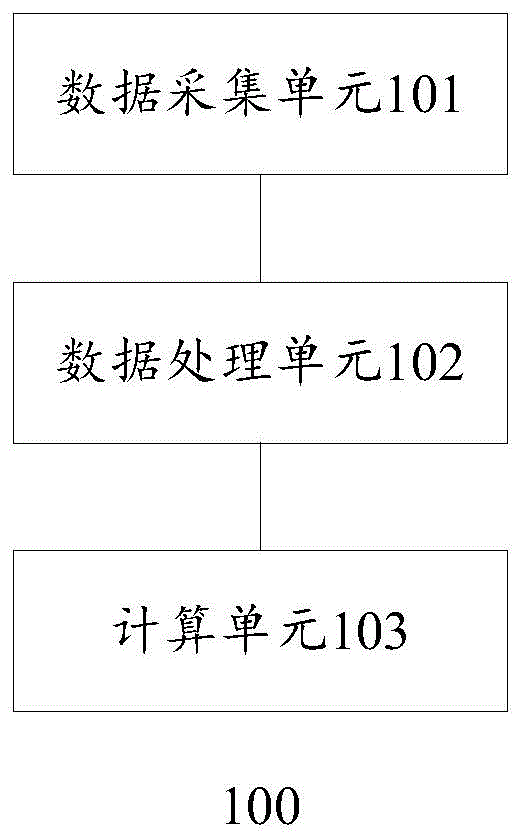
Fig. 1 is a schematic diagram illustrating a vehicle assistance system 100 according to one embodiment of the invention. The vehicle assistance system 100 is configured to calculate a merging probability of a target vehicle for a current vehicle based on an artificial intelligence model. The artificial intelligence model may be a trained convolutional neural network model or other machine learning model known in the art, preferably the LeNet-5 architecture.
As shown in fig. 1, the vehicle assistance system 100 includes: a data acquisition unit 101, a data processing unit 102 and a calculation unit 103. The data acquisition unit 101 is in communication with the data processing unit 102, and the data processing unit 102 is in communication with the computing unit 103. The configuration and functions of the respective units of the vehicle assistance system 100 will be described in detail below.
Some or all of the units of the vehicle assistance system 100 may be located on the current vehicle and/or on a remote server. In one embodiment, the data acquisition unit 101 may acquire the acceleration, the traveling direction, the position relative to the current vehicle, and the distance of the target vehicle through various types of sensors provided on the current vehicle. For example, the sensor may include a camera, a lidar, a millimeter-wave radar, an ultrasonic sensor, or any other suitable sensor, or any combination thereof. Alternatively, in another embodiment, the relative position and/or distance of the target vehicle with respect to the current vehicle may also be obtained through vehicle-to-vehicle communication V2V (via a mobile network or Wi-Fi, etc.) between the current vehicle and the target vehicle. For example, the data collection unit 101 may communicate with the target vehicle to obtain a Global Navigation Satellite System (GNSS) position or navigation map data about the target vehicle provided by a GNSS installed on the target vehicle, and then the data collection unit 101 may calculate a relative position and/or distance of the target vehicle with respect to the current vehicle using the GNSS position or navigation map data of the target vehicle and the GNSS position or navigation map data of the current vehicle.
The data acquisition unit 101 may be configured to detect a relative position of the target vehicle with respect to the current vehicle, start acquiring data related to the target vehicle in a plurality of consecutive preset time slots when it is detected that the target vehicle is present at a first preset angle with respect to the current vehicle on a rear side of the current vehicle, until the data acquisition unit 101 detects that the target vehicle is present at a second preset angle with respect to the current vehicle on a side of the current vehicle, wherein the acquired data includes at least an acceleration of the target vehicle, a traveling direction of the target vehicle, and a distance between the target vehicle and the current vehicle.
The first preset angle may be selected between 45 degrees and 60 degrees (inclusive) of end point values of 45 degrees and 60 degrees on the rear side of the current vehicle at the target vehicle. Preferably, in one embodiment, the first preset angle refers to that the target vehicle is located at 45 degrees behind the current vehicle.
The second preset angle may be selected from the group consisting of the target vehicle being located at a rear side of the current vehicle by more than 0 degrees to 10 degrees or less, the target vehicle being located at 0 degrees when parallel to the current vehicle, the target vehicle being located at a front side of the current vehicle by more than 0 degrees to 45 degrees or less. For example, in one embodiment, the second preset angle is 0 degrees when the target vehicle is parallel to the current vehicle.
In particular, reference may be made to the accompanying fig. 3A-3C with respect to specific illustrative examples of the first and second preset angles, as described in further detail below.
The data processing unit 102 may be configured to generate a matrix set by using data collected in each preset time slot, and output the matrix set at the end of each preset time slot, wherein the matrix set includes at least three matrix layers respectively associated with a corresponding one type of data in the collected data. For example, when the collected data are only the above-mentioned three types of data (i.e., the acceleration of the target vehicle, the traveling direction, and the distance between the target vehicle and the current vehicle), the matrix set output at the end of each preset time slot may include only three matrix layers, which may be respectively related to the acceleration of the target vehicle, the advancing direction of the target vehicle, and the distance between the target vehicle and the current vehicle. Of course, it is also contemplated by those skilled in the art to gather more travel related data about the target vehicle to provide a more accurate prediction of the likelihood of a merge.
The time length of the preset time slot may be any value selected by those skilled in the art from 1s to 3s, including a preset time slot of 1s, a preset time slot of 2s, or a preset time slot of 3 s. In one embodiment where the predetermined time slot is 1s, within each predetermined time slot, relevant data may be collected at M times (e.g., 100 times) at fixed time intervals of 1/M second (e.g., 1/100 or other values) to generate a matrix set covering all data collected at the M times from the beginning of the time slot to the end of the time slot at the end of the corresponding predetermined time slot.
The calculation unit 103 may be configured to calculate the merging possibility of the target vehicle by inputting each of the output matrix sets to an artificial intelligence model. In one embodiment, the calculating the merging possibility of the target vehicle may include: and respectively calculating the merging possibility of the target vehicle represented by each matrix set by using an artificial intelligence model, and then calculating the total merging possibility of the target vehicle by multiplying each merging possibility by a corresponding preset weighted value and summing.
In one embodiment, it is assumed that four preset time slots (T) follow one another during the entire data acquisition process1-T4) At the end, four matrix sets (P1-P4) are generated, each matrix set including at least three matrix layers, then the overall likelihood of merging for the target vehicle can be calculated according to the following formula:
Poverall=P1×w1+P2×w2+P3×w3+P4×w4 (1)
wherein P isoverallRepresenting the calculated overall merging possibility of the target vehicle, P1-P4 respectively representing the merging possibility of the target vehicle represented by each matrix set in the corresponding preset time slot, and w1-w4 respectively representing weighted values of the merging possibilities of the target vehicle corresponding to each matrix set. Preferably, w1 < w2 < w3 < w 4. However, w1-w4 may be set according to an empirical value, a time length of a preset time slot, or a safety requirement of the vehicle. Of course, as will be understood by those skilled in the art, the above formula for calculating the target vehicle overall merging possibility also needs to be adaptively modified in the case where more or fewer time slots are included within the detection period in which the condition is satisfied.
In another embodiment, the target vehicle is detected to be present at a first preset angle (the current time is denoted T) to the rear side of the current vehicle with respect to the current vehicle0) And also at the current time T0Immediately querying a previous preset time slot-T1Whether or not relevant data relating to the target vehicle have been recorded by corresponding sensors or other vehicle-to-vehicle communication means, if a preceding predetermined time slot-T1Having recorded therein relevant data relating to the target vehicle, it is possible to directly upon satisfaction of the trigger condition for starting the acquisition (i.e. T;)0) Direct acquisition of prior time slot-T1Relevant data regarding the target vehicle is recorded. Using preceding time slot-T1The set of matrices generated by the data of the inner records can be represented as P0, and the corresponding weight can be represented as w 0.
Thus, the above formula for calculating the total merging possibility of the target vehicle may be adaptively modified as follows:
Poverall=P0×w0+P1×w1+P2×w2+P3×w3+P4×w4 (2)
further, a threshold value of the possibility of merging may be set in advance so that the vehicle assist system 100 may compare the calculated total possibility of merging of the target vehicles with the preset threshold value of the possibility of merging. For example, if PoverallThe possibility of the target vehicle to be subjected to doubling is high if the value is larger than or equal to the threshold value, and if P is larger than or equal to the threshold value, the target vehicle is prompted to be subjected to doublingoverallIf the threshold value is less than the threshold value, the target vehicle is prompted to be less likely to be subjected to line doubling. The vehicle assistance system 100 may prompt the merging possibility of the target vehicle through voice broadcasting, holographic projection, augmented reality display, on-vehicle display terminal display, and/or portable smart device (smart phone, smart watch, smart band) display worn by the vehicle user, and control the current vehicle to take corresponding measures such as deceleration braking or emergency braking when the possibility of merging of the target vehicle is high.
According to another aspect of the invention, a vehicle is provided, wherein the vehicle may comprise the vehicle assistance system described above. The vehicle may be any type of vehicle, including a vehicle driven by a person or an autonomous vehicle.
FIG. 2 is a flow diagram illustrating a vehicle assistance method 200 according to one embodiment of the invention.
The vehicle assist method 200 is for calculating a merging possibility of a target vehicle for a current vehicle based on an artificial intelligence model, and the vehicle assist method 200 includes the steps of:
a data acquisition step 201: detecting a relative position of the target vehicle with respect to the current vehicle, starting to collect data related to the target vehicle in a plurality of consecutive preset time slots when it is detected that the target vehicle appears at a first preset angle with respect to the current vehicle on a rear side of the current vehicle until it is detected that the target vehicle appears at a second preset angle with respect to the current vehicle on a side of the current vehicle, wherein the collected data comprises at least an acceleration of the target vehicle, a traveling direction of the target vehicle and a distance between the target vehicle and the current vehicle;
data processing step 202: generating a matrix set by using data collected in each preset time slot, and outputting the matrix set at the end of each preset time slot, wherein the matrix set comprises at least three matrix layers which are respectively related to corresponding one type of data in the collected data; and
a calculation step 203: calculating a merging probability of the target vehicle by inputting each matrix set outputted to an artificial intelligence model.
It should be understood that the specific features described herein above with respect to the vehicle assistance system may similarly be applied to similar extensions in the vehicle assistance method. For the sake of simplicity, these specific features are not described again in detail.
Fig. 3A, 3B, and 3C illustrate a situation when the target vehicle appears on the rear side of the current vehicle, a situation when the target vehicle runs parallel to the current vehicle, and a situation when the target vehicle appears on the front side of the current vehicle, respectively, in some embodiments.
Referring now to fig. 3A, fig. 3A illustrates a situation when the target vehicle appears at a first preset angle to the current vehicle on the rear side of the current vehicle. In fig. 3A, the traveling direction of the vehicle (as indicated by an arrow), the position reference point R0 on the present vehicle, the position detection point R1 on the target vehicle, a reference line L0 horizontally extending from the reference point R0 with respect to the present vehicle, and a straight line L1 formed by connecting the position reference point R0 on the present vehicle and the position detection point R1 on the target vehicle are shown. As shown in fig. 3A, the target vehicle is located on the rear side of the current vehicle and forms an angle with the current vehicle (i.e., an angle α between a straight line L1 and a reference line L0)1) Is 45 degrees. Assuming that the first preset angle is 45 degrees, the data acquisition unit 101 may be triggered to start acquiring data related to the target vehicle when the situation of fig. 3A is detected.
It should be understood by those skilled in the art that although the reference point R0 is shown in fig. 3A as being located at a middle position on the foremost side of the head of the current vehicle and the detection point R1 is shown as being located at a middle position on the foremost side of the head of the target vehicle, the positions of the reference point R0 and the detection point R1 may be appropriately selected according to the installation position of the sensor or the need of other detection means.
As the current vehicle and the target vehicle continue to travel, the relative position of the target vehicle with respect to the current vehicle changes continuously. The situations shown in fig. 3B and 3C may occur sequentially.
Fig. 3B shows a situation when the target vehicle is parallel to the current vehicle. The direction of travel of the vehicle is also shown in fig. 3B (as indicated by the arrow) where the line L1 coincides with the reference line L0, i.e., the angle α formed by the line L1 and the reference line L0210 deg.. Assuming that the second preset angle is 0 degrees when the target vehicle is parallel to the current vehicle, at this time, the data acquisition unit 101 may stop acquiring data related to the target vehicle, and then may generate a corresponding matrix set using the acquired data to further calculate a merging possibility of the target vehicle using an artificial intelligence model.
Fig. 3C shows a situation when the target vehicle appears on the front side of the present vehicle. The traveling direction of the vehicle (as indicated by the arrow) is also shown in fig. 3C, in which the target vehicle travels to the front side of the current vehicle, and the angle α formed by the straight line L1 and the reference line L0 of the current vehicle 2230 ° is set. Assuming that the second preset angle is 30 degrees ahead of the target vehicle, at this time, the data acquisition unit 101 may stop acquiring data related to the target vehicle, and then may generate a corresponding matrix set from the acquired data to further calculate a merging possibility of the target vehicle using an artificial intelligence model.
Preferably, the artificial intelligence model referred to herein may be formed by training as follows: a large number of different actual or virtual doubling scenes (for example, a complete process including actual doubling actions) are continuously machine-learned in advance by using the data acquisition step, the data processing step and the calculation step, so that various calculation parameters in the artificial intelligence model are optimized. For example, in the training process, different labels or weights may be set for different matrix layers in the matrix set, or different weights may be set for matrix sets of different time slots, so as to obtain an artificial intelligence model with optimal parameter settings and optimal prediction accuracy in the continuous machine learning process.
It should be understood that the various elements of the vehicle assistance system of the present invention may be implemented in whole or in part in software, hardware, firmware, or a combination thereof. The units may be embedded in a processor of the computer device in a hardware or firmware form or independent of the processor, or may be stored in a memory of the computer device in a software form for being called by the processor to execute operations of the units. Each of the units may be implemented as a separate component or module, or two or more units may be implemented as a single component or module.
It will be appreciated by those of ordinary skill in the art that the schematic diagram of the vehicle assistance system shown in fig. 1 is merely an illustrative block diagram of a portion of the structure associated with aspects of the present invention and does not constitute a limitation of the computer device, processor or computer program embodying aspects of the present invention. A particular computer device, processor or computer program may include more or fewer components or modules than shown in the figures, or may combine or split certain components or modules, or may have a different arrangement of components or modules.
The invention may be implemented as a computer-readable storage medium having stored thereon a computer program which, when executed by a processor, causes the steps of the method of the invention to be performed. In one embodiment, the computer program is distributed across a plurality of computer devices or processors coupled by a network such that the computer program is stored, accessed, and executed by one or more computer devices or processors in a distributed fashion. One or more method steps/operations may be performed by one or more computer devices or processors, and one or more other method steps/operations may be performed by one or more other computer devices or processors. One or more computer devices or processors may perform a single method step/operation, or perform two or more method steps/operations.
It will be understood by those skilled in the art that all or part of the steps of the assistance method of the present invention may be instructed to be performed by associated hardware such as a computer device or a processor through a computer program, which may be stored in a non-transitory computer readable storage medium, and which when executed causes the steps of the assistance method of the present invention to be performed. Any reference herein to memory, storage, databases, or other media may include non-volatile and/or volatile memory, as appropriate. Examples of non-volatile memory include read-only memory (ROM), Programmable ROM (PROM), Electrically Programmable ROM (EPROM), Electrically Erasable Programmable ROM (EEPROM), flash memory, magnetic tape, floppy disk, magnetic data storage device, optical data storage device, hard disk, solid state disk, and the like. Examples of volatile memory include Random Access Memory (RAM), external cache memory, and the like.
The respective technical features described above may be arbitrarily combined. Although not all possible combinations of features are described, any combination of features should be considered to be covered by the present specification as long as there is no contradiction between such combinations.
While the invention has been described in connection with the embodiments, it is to be understood by those skilled in the art that the foregoing description and drawings are merely illustrative and not restrictive of the broad invention, and that this invention not be limited to the disclosed embodiments. Various modifications and variations are possible without departing from the spirit of the invention.