CN113384359A - Medical control apparatus, control method, program, and medical control system - Google Patents
Medical control apparatus, control method, program, and medical control system Download PDFInfo
- Publication number
- CN113384359A CN113384359A CN202110496002.4A CN202110496002A CN113384359A CN 113384359 A CN113384359 A CN 113384359A CN 202110496002 A CN202110496002 A CN 202110496002A CN 113384359 A CN113384359 A CN 113384359A
- Authority
- CN
- China
- Prior art keywords
- display area
- display
- displayed
- screen
- output destination
- Prior art date
- Legal status (The legal status is an assumption and is not a legal conclusion. Google has not performed a legal analysis and makes no representation as to the accuracy of the status listed.)
- Granted
Links
Images


Classifications
-
- H—ELECTRICITY
- H04—ELECTRIC COMMUNICATION TECHNIQUE
- H04N—PICTORIAL COMMUNICATION, e.g. TELEVISION
- H04N21/00—Selective content distribution, e.g. interactive television or video on demand [VOD]
- H04N21/40—Client devices specifically adapted for the reception of or interaction with content, e.g. set-top-box [STB]; Operations thereof
- H04N21/43—Processing of content or additional data, e.g. demultiplexing additional data from a digital video stream; Elementary client operations, e.g. monitoring of home network or synchronising decoder's clock; Client middleware
- H04N21/431—Generation of visual interfaces for content selection or interaction; Content or additional data rendering
- H04N21/4312—Generation of visual interfaces for content selection or interaction; Content or additional data rendering involving specific graphical features, e.g. screen layout, special fonts or colors, blinking icons, highlights or animations
-
- A—HUMAN NECESSITIES
- A61—MEDICAL OR VETERINARY SCIENCE; HYGIENE
- A61B—DIAGNOSIS; SURGERY; IDENTIFICATION
- A61B1/00—Instruments for performing medical examinations of the interior of cavities or tubes of the body by visual or photographical inspection, e.g. endoscopes; Illuminating arrangements therefor
- A61B1/00002—Operational features of endoscopes
- A61B1/00043—Operational features of endoscopes provided with output arrangements
- A61B1/00045—Display arrangement
- A61B1/0005—Display arrangement combining images e.g. side-by-side, superimposed or tiled
-
- A—HUMAN NECESSITIES
- A61—MEDICAL OR VETERINARY SCIENCE; HYGIENE
- A61B—DIAGNOSIS; SURGERY; IDENTIFICATION
- A61B34/00—Computer-aided surgery; Manipulators or robots specially adapted for use in surgery
- A61B34/25—User interfaces for surgical systems
-
- A—HUMAN NECESSITIES
- A61—MEDICAL OR VETERINARY SCIENCE; HYGIENE
- A61B—DIAGNOSIS; SURGERY; IDENTIFICATION
- A61B90/00—Instruments, implements or accessories specially adapted for surgery or diagnosis and not covered by any of the groups A61B1/00 - A61B50/00, e.g. for luxation treatment or for protecting wound edges
- A61B90/36—Image-producing devices or illumination devices not otherwise provided for
- A61B90/37—Surgical systems with images on a monitor during operation
-
- G—PHYSICS
- G06—COMPUTING OR CALCULATING; COUNTING
- G06F—ELECTRIC DIGITAL DATA PROCESSING
- G06F3/00—Input arrangements for transferring data to be processed into a form capable of being handled by the computer; Output arrangements for transferring data from processing unit to output unit, e.g. interface arrangements
- G06F3/01—Input arrangements or combined input and output arrangements for interaction between user and computer
- G06F3/048—Interaction techniques based on graphical user interfaces [GUI]
- G06F3/0481—Interaction techniques based on graphical user interfaces [GUI] based on specific properties of the displayed interaction object or a metaphor-based environment, e.g. interaction with desktop elements like windows or icons, or assisted by a cursor's changing behaviour or appearance
- G06F3/0482—Interaction with lists of selectable items, e.g. menus
-
- G—PHYSICS
- G06—COMPUTING OR CALCULATING; COUNTING
- G06F—ELECTRIC DIGITAL DATA PROCESSING
- G06F3/00—Input arrangements for transferring data to be processed into a form capable of being handled by the computer; Output arrangements for transferring data from processing unit to output unit, e.g. interface arrangements
- G06F3/01—Input arrangements or combined input and output arrangements for interaction between user and computer
- G06F3/048—Interaction techniques based on graphical user interfaces [GUI]
- G06F3/0487—Interaction techniques based on graphical user interfaces [GUI] using specific features provided by the input device, e.g. functions controlled by the rotation of a mouse with dual sensing arrangements, or of the nature of the input device, e.g. tap gestures based on pressure sensed by a digitiser
- G06F3/0488—Interaction techniques based on graphical user interfaces [GUI] using specific features provided by the input device, e.g. functions controlled by the rotation of a mouse with dual sensing arrangements, or of the nature of the input device, e.g. tap gestures based on pressure sensed by a digitiser using a touch-screen or digitiser, e.g. input of commands through traced gestures
-
- G—PHYSICS
- G09—EDUCATION; CRYPTOGRAPHY; DISPLAY; ADVERTISING; SEALS
- G09G—ARRANGEMENTS OR CIRCUITS FOR CONTROL OF INDICATING DEVICES USING STATIC MEANS TO PRESENT VARIABLE INFORMATION
- G09G5/00—Control arrangements or circuits for visual indicators common to cathode-ray tube indicators and other visual indicators
- G09G5/14—Display of multiple viewports
-
- G—PHYSICS
- G16—INFORMATION AND COMMUNICATION TECHNOLOGY [ICT] SPECIALLY ADAPTED FOR SPECIFIC APPLICATION FIELDS
- G16H—HEALTHCARE INFORMATICS, i.e. INFORMATION AND COMMUNICATION TECHNOLOGY [ICT] SPECIALLY ADAPTED FOR THE HANDLING OR PROCESSING OF MEDICAL OR HEALTHCARE DATA
- G16H30/00—ICT specially adapted for the handling or processing of medical images
- G16H30/20—ICT specially adapted for the handling or processing of medical images for handling medical images, e.g. DICOM, HL7 or PACS
-
- G—PHYSICS
- G16—INFORMATION AND COMMUNICATION TECHNOLOGY [ICT] SPECIALLY ADAPTED FOR SPECIFIC APPLICATION FIELDS
- G16H—HEALTHCARE INFORMATICS, i.e. INFORMATION AND COMMUNICATION TECHNOLOGY [ICT] SPECIALLY ADAPTED FOR THE HANDLING OR PROCESSING OF MEDICAL OR HEALTHCARE DATA
- G16H40/00—ICT specially adapted for the management or administration of healthcare resources or facilities; ICT specially adapted for the management or operation of medical equipment or devices
- G16H40/60—ICT specially adapted for the management or administration of healthcare resources or facilities; ICT specially adapted for the management or operation of medical equipment or devices for the operation of medical equipment or devices
- G16H40/63—ICT specially adapted for the management or administration of healthcare resources or facilities; ICT specially adapted for the management or operation of medical equipment or devices for the operation of medical equipment or devices for local operation
-
- H—ELECTRICITY
- H04—ELECTRIC COMMUNICATION TECHNIQUE
- H04N—PICTORIAL COMMUNICATION, e.g. TELEVISION
- H04N21/00—Selective content distribution, e.g. interactive television or video on demand [VOD]
- H04N21/20—Servers specifically adapted for the distribution of content, e.g. VOD servers; Operations thereof
- H04N21/21—Server components or server architectures
- H04N21/214—Specialised server platform, e.g. server located in an airplane, hotel, hospital
-
- H—ELECTRICITY
- H04—ELECTRIC COMMUNICATION TECHNIQUE
- H04N—PICTORIAL COMMUNICATION, e.g. TELEVISION
- H04N21/00—Selective content distribution, e.g. interactive television or video on demand [VOD]
- H04N21/20—Servers specifically adapted for the distribution of content, e.g. VOD servers; Operations thereof
- H04N21/23—Processing of content or additional data; Elementary server operations; Server middleware
- H04N21/234—Processing of video elementary streams, e.g. splicing of video streams or manipulating encoded video stream scene graphs
- H04N21/2343—Processing of video elementary streams, e.g. splicing of video streams or manipulating encoded video stream scene graphs involving reformatting operations of video signals for distribution or compliance with end-user requests or end-user device requirements
- H04N21/234309—Processing of video elementary streams, e.g. splicing of video streams or manipulating encoded video stream scene graphs involving reformatting operations of video signals for distribution or compliance with end-user requests or end-user device requirements by transcoding between formats or standards, e.g. from MPEG-2 to MPEG-4 or from Quicktime to Realvideo
-
- H—ELECTRICITY
- H04—ELECTRIC COMMUNICATION TECHNIQUE
- H04N—PICTORIAL COMMUNICATION, e.g. TELEVISION
- H04N21/00—Selective content distribution, e.g. interactive television or video on demand [VOD]
- H04N21/40—Client devices specifically adapted for the reception of or interaction with content, e.g. set-top-box [STB]; Operations thereof
- H04N21/43—Processing of content or additional data, e.g. demultiplexing additional data from a digital video stream; Elementary client operations, e.g. monitoring of home network or synchronising decoder's clock; Client middleware
- H04N21/431—Generation of visual interfaces for content selection or interaction; Content or additional data rendering
-
- H—ELECTRICITY
- H04—ELECTRIC COMMUNICATION TECHNIQUE
- H04N—PICTORIAL COMMUNICATION, e.g. TELEVISION
- H04N21/00—Selective content distribution, e.g. interactive television or video on demand [VOD]
- H04N21/40—Client devices specifically adapted for the reception of or interaction with content, e.g. set-top-box [STB]; Operations thereof
- H04N21/43—Processing of content or additional data, e.g. demultiplexing additional data from a digital video stream; Elementary client operations, e.g. monitoring of home network or synchronising decoder's clock; Client middleware
- H04N21/436—Interfacing a local distribution network, e.g. communicating with another STB or one or more peripheral devices inside the home
-
- A—HUMAN NECESSITIES
- A61—MEDICAL OR VETERINARY SCIENCE; HYGIENE
- A61B—DIAGNOSIS; SURGERY; IDENTIFICATION
- A61B90/00—Instruments, implements or accessories specially adapted for surgery or diagnosis and not covered by any of the groups A61B1/00 - A61B50/00, e.g. for luxation treatment or for protecting wound edges
- A61B90/36—Image-producing devices or illumination devices not otherwise provided for
- A61B90/37—Surgical systems with images on a monitor during operation
- A61B2090/371—Surgical systems with images on a monitor during operation with simultaneous use of two cameras
-
- G—PHYSICS
- G06—COMPUTING OR CALCULATING; COUNTING
- G06F—ELECTRIC DIGITAL DATA PROCESSING
- G06F2203/00—Indexing scheme relating to G06F3/00 - G06F3/048
- G06F2203/048—Indexing scheme relating to G06F3/048
- G06F2203/04803—Split screen, i.e. subdividing the display area or the window area into separate subareas
-
- G—PHYSICS
- G06—COMPUTING OR CALCULATING; COUNTING
- G06F—ELECTRIC DIGITAL DATA PROCESSING
- G06F3/00—Input arrangements for transferring data to be processed into a form capable of being handled by the computer; Output arrangements for transferring data from processing unit to output unit, e.g. interface arrangements
- G06F3/01—Input arrangements or combined input and output arrangements for interaction between user and computer
- G06F3/048—Interaction techniques based on graphical user interfaces [GUI]
- G06F3/0481—Interaction techniques based on graphical user interfaces [GUI] based on specific properties of the displayed interaction object or a metaphor-based environment, e.g. interaction with desktop elements like windows or icons, or assisted by a cursor's changing behaviour or appearance
- G06F3/0483—Interaction with page-structured environments, e.g. book metaphor
-
- G—PHYSICS
- G09—EDUCATION; CRYPTOGRAPHY; DISPLAY; ADVERTISING; SEALS
- G09G—ARRANGEMENTS OR CIRCUITS FOR CONTROL OF INDICATING DEVICES USING STATIC MEANS TO PRESENT VARIABLE INFORMATION
- G09G2354/00—Aspects of interface with display user
-
- G—PHYSICS
- G09—EDUCATION; CRYPTOGRAPHY; DISPLAY; ADVERTISING; SEALS
- G09G—ARRANGEMENTS OR CIRCUITS FOR CONTROL OF INDICATING DEVICES USING STATIC MEANS TO PRESENT VARIABLE INFORMATION
- G09G2380/00—Specific applications
- G09G2380/08—Biomedical applications
Landscapes
- Engineering & Computer Science (AREA)
- Health & Medical Sciences (AREA)
- Life Sciences & Earth Sciences (AREA)
- Surgery (AREA)
- Nuclear Medicine, Radiotherapy & Molecular Imaging (AREA)
- Public Health (AREA)
- Biomedical Technology (AREA)
- Medical Informatics (AREA)
- General Health & Medical Sciences (AREA)
- Theoretical Computer Science (AREA)
- Physics & Mathematics (AREA)
- General Engineering & Computer Science (AREA)
- Radiology & Medical Imaging (AREA)
- Heart & Thoracic Surgery (AREA)
- Veterinary Medicine (AREA)
- Animal Behavior & Ethology (AREA)
- Molecular Biology (AREA)
- General Physics & Mathematics (AREA)
- Pathology (AREA)
- Human Computer Interaction (AREA)
- Multimedia (AREA)
- Signal Processing (AREA)
- Primary Health Care (AREA)
- Epidemiology (AREA)
- Oral & Maxillofacial Surgery (AREA)
- Gynecology & Obstetrics (AREA)
- General Business, Economics & Management (AREA)
- Business, Economics & Management (AREA)
- Biophysics (AREA)
- Optics & Photonics (AREA)
- Computer Hardware Design (AREA)
- Robotics (AREA)
- User Interface Of Digital Computer (AREA)
- Controls And Circuits For Display Device (AREA)
- Endoscopes (AREA)
Abstract
本发明公开了医疗控制设备、控制方法、程序以及医疗控制系统。该医疗控制设备具备处理单元,其在一个画面中显示:第一显示区域,其中,显示与图像的输入源有关的对象;和/或第二显示区域,其中,显示与图像的输出目的地有关的对象;以及第三显示区域,其中,显示用于控制输入源或输出目的地的对象。
The invention discloses medical control equipment, a control method, a program and a medical control system. The medical control device is provided with a processing unit that displays in one screen: a first display area in which objects related to the input source of the image are displayed; and/or a second display area in which the display related to the output destination of the image is displayed and a third display area, in which an object for controlling the input source or output destination is displayed.
Description
The present application is a divisional application, and its parent application has application number of 2016800559802, and application date of 2016, 8, and 16, entitled "medical control device, control method, program, and medical control system".
Technical Field
The present invention relates to a medical control apparatus, a control method, a program, and a medical control system.
Background
A technology related to a medical control system that connects a plurality of devices by communication has been developed. Examples of the technology relating to the medical control system may include, for example, the technology disclosed in patent document 1 below and the technology disclosed in patent document 2 below.
CITATION LIST
Patent document
Patent document 1: JP 2001 + 000449A
Patent document 2: JP 2006 + 000536A
Disclosure of Invention
Technical problem
The medical control system includes, for example, a medical control apparatus such as an Operating Room (OR) controller for controlling input/output of images (still images OR moving images). Here, typical conventional medical control apparatuses are, for example, such that "an apparatus which becomes a signal source of an image signal (for example, a medical apparatus having an imaging function such as an endoscope) and an imaging device installed in an operating room" which constitute a medical control system and "an apparatus which becomes an output destination of an image, for example, a display device which can display an image" are displayed on one screen. The existing medical control apparatus switches between input and output of images based on, for example, an operation of a user of the medical control system (for example, a medical professional hereinafter simply referred to as "user"). In the following description, there is a case where a device which becomes a signal source of an image signal is referred to as an "input source". Further, in the following description, there is a case where an apparatus which becomes an output destination of an image is referred to as an "output destination".
As described above, by causing the medical control apparatus that constitutes the input source and the output destination of the medical control system to be displayed on one screen, the viewability of the input source and the output destination is improved. Therefore, as described above, by causing the medical control apparatus that constitutes the input source and the output destination of the medical control system to be displayed in one screen, there is a possibility that the visibility of the input source and the output destination may be improved.
However, in the case of using the above-described conventional medical control apparatus, control associated with input/output of an image and control of an apparatus (input source or output destination) constituting the medical control system cannot be performed on one screen.
The present disclosure proposes a novel and improved medical control apparatus, a control method, a program, and a medical control system, which can improve the operability of a user.
Means for solving the problems
According to the present disclosure, there is provided a medical control apparatus including: a processing unit configured to cause one or both of a first display area in which an object related to an input source of an image is displayed and a second display area in which an object related to an output destination of an image is displayed and a third display area in which an object for controlling the input source or the output destination is displayed to be displayed in one screen.
Further, according to the present disclosure, there is provided a control method performed by a medical control apparatus, the method including: a step of displaying one or both of a first display area in which an object related to an input source of an image is displayed, a second display area in which an object related to an output destination of an image is displayed, and a third display area in which an object for controlling the input source or the output destination is displayed, in one screen.
Further, according to the present disclosure, there is provided a program for causing a computer to execute the functions of: a first display area in which an object related to an input source of an image is displayed, a second display area in which an object related to an output destination of an image is displayed, and a third display area in which an object for controlling the input source or the output destination is displayed are displayed in one screen.
Further, according to the present disclosure, there is provided a medical control system including: a device serving as an input source of an image; a device serving as an output destination of an image; and a medical control apparatus, wherein the medical control apparatus includes a processing unit configured to cause one or both of a first display area in which an object related to the input source is displayed and a second display area in which an object related to the output destination is displayed, and a third display area in which an object for controlling the input source or the output destination is displayed to be displayed in one screen.
The invention has the advantages of
According to the present disclosure, the operability of the user can be improved.
Note that the above effects are not necessarily restrictive. Any one of the effects described in the present specification or other effects that can be understood from the present specification can be achieved with or instead of the above-described effects.
Drawings
Fig. 1 is an explanatory diagram showing an example of a medical control system according to the present embodiment.
Fig. 2 is an explanatory diagram for explaining a display example of a medical control system to which the control method according to the present embodiment is applied.
Fig. 3 is an explanatory diagram for explaining a display example of a medical control system to which the control method according to the present embodiment is applied.
Fig. 4 is an explanatory diagram for explaining a display example of a medical control system to which the control method according to the present embodiment is applied.
Fig. 5 is an explanatory diagram for explaining a display example of a medical control system to which the control method according to the present embodiment is applied.
Fig. 6 is an explanatory diagram for explaining a display example of a medical control system to which the control method according to the present embodiment is applied.
FIG. 7 is an explanatory diagram for explaining a display example of a medical control system to which the control method of the present embodiment is applied;
fig. 8 is an explanatory diagram for explaining a display example of a medical control system to which the control method according to the present embodiment is applied.
Fig. 9 is an explanatory diagram for explaining a display example of a medical control system to which the control method according to the present embodiment is applied.
Fig. 10 is an explanatory diagram for explaining a display example of a medical control system to which the control method according to the present embodiment is applied.
Fig. 11 is an explanatory diagram for explaining a display example of a medical control system to which the control method according to the present embodiment is applied.
Fig. 12 is an explanatory diagram for explaining a display example of a medical control system to which the control method according to the present embodiment is applied.
Fig. 13 is an explanatory diagram for explaining a display example of a medical control system to which the control method according to the present embodiment is applied.
Fig. 14 is an explanatory diagram for explaining a display example of a medical control system to which the control method according to the present embodiment is applied.
Fig. 15 is an explanatory diagram for explaining a display example of a medical control system to which the control method according to the present embodiment is applied.
Fig. 16 is an explanatory diagram for explaining a display example of a medical control system to which the control method according to the present embodiment is applied.
Fig. 17 is an explanatory diagram for explaining a display example of a medical control system to which the control method according to the present embodiment is applied.
Fig. 18 is an explanatory diagram for explaining a display example of a medical control system to which the control method according to the present embodiment is applied.
Fig. 19A is an explanatory diagram for explaining a display example of a medical control system to which the control method according to the present embodiment is applied.
Fig. 19B is an explanatory diagram for explaining a display example of a medical control system to which the control method according to the present embodiment is applied.
Fig. 20 is a block diagram showing a configuration example of the medical control apparatus according to the present embodiment.
Fig. 21 is an explanatory diagram showing an example of the hardware configuration of the medical control apparatus according to the present embodiment.
Detailed Description
Hereinafter, preferred embodiments of the present disclosure will be described in detail with reference to the accompanying drawings. Note that in the present specification and the drawings, structural elements having substantially the same function and structure are denoted by the same reference numerals, and repeated explanation of these structural elements is omitted.
Further, in the following description, the description will be provided in the following order.
1. Control method according to the present embodiment
2. Medical control apparatus according to the present embodiment
3. Program according to the present embodiment
(control method according to the embodiment)
First, the control method according to the present embodiment will be described. In the following description, an example will be described in which the medical control apparatus according to the present embodiment performs processing associated with the control method according to the present embodiment.
【1】 Processing associated with the control method according to the present embodiment
As described above, in the case of using the existing medical control apparatus, it is impossible to perform control relating to input/output of an image and control of an apparatus (input source or output destination) constituting the medical control system in one screen.
Therefore, the medical control apparatus according to the present embodiment is capable of executing control relating to input/output of an image and control of an input source or an output destination constituting a medical control system in one screen.
Here, examples of the input source according to the present embodiment may include, for example, any device (for example, a medical device having an imaging function such as an endoscope) which can be a signal source of an image signal, an imaging apparatus provided in an operating room, and a device having a function of reproducing image data stored in a recording medium.
Further, examples of the output destination according to the present embodiment may include, for example, any device that can be an output destination of an image, such as a display device that can display an image and a device having a function of recording an image in a recording medium.
More specifically, for example, as described in the following display examples (1) to (3) (control processing), the medical control apparatus according to the present embodiment causes a plurality of display areas to be displayed in one screen.
Examples of the display screen according to the present embodiment to display a plurality of display regions may include, for example, a display screen of a display apparatus provided on an arbitrary device (or a display apparatus connected to an arbitrary device), for example, a tablet type device, a computer (e.g., a Personal Computer (PC)), and a communication apparatus (e.g., a smartphone). Further, the display device constituting the display screen according to the present embodiment may be a device such as a touch panel which can perform display and allow a user operation.
The medical control apparatus according to the present embodiment causes a plurality of display areas to be displayed in one screen by, for example, causing control data including a command for causing display to be performed and display data to be transmitted to an apparatus that displays a plurality of display areas in one screen (hereinafter, there is a case where the apparatus will be referred to as a "display target apparatus"). For example, the medical control apparatus according to the present embodiment causes a communication unit (to be described later) provided at the medical control apparatus according to the present embodiment or an external communication device embodiment connected to the medical control apparatus according to the present embodiment to transmit control data.
By performing the control processing as described above, the medical control apparatus according to the present embodiment can execute control relating to input/output of an image and control of an input source or an output destination constituting the medical control system in one screen.
Here, examples of the display area displayed in one screen according to the present embodiment may include, for example, the following first display area, second display area, and third display area.
-a first display area: display area for displaying object related to input source of image
-a second display area: display area for displaying object related to output destination of image
-a third display area: display area for displaying object for controlling input source or output destination
Further, examples of the object according to the present embodiment may include any display object that can be displayed on the display screen, such as "thumbnail image corresponding to an image output from an input source or an image input to an output destination", "character string", and "operation object such as a button and a slider that can be operated by a user". A specific example of the object according to the present embodiment will be described in a display example in a medical control system described later.
Here, examples of the thumbnail image according to the present embodiment may include a still image and a moving image. Further, the thumbnail image according to the present embodiment may be updated periodically, for example, every 1 [ FPS ], or may be updated irregularly. By updating the thumbnail image, the image that is newly output from the input source or the image that is newly input to the output destination can be reflected in the thumbnail image.
(1) First example of display in one screen by control processing
The medical control apparatus according to the present embodiment causes the first display area, the second display area, and the third display area to be displayed in one screen.
In the case where the display according to the first example is performed, the medical control apparatus according to the present embodiment causes the following objects to be displayed in the first display area, the second display area, and the third display area, respectively.
-a first display area: input source related object
-a second display area: object related to output destination capable of displaying image of input source
-a third display area: object for controlling input source
A specific example of the display according to the first example may include, for example, a source screen on an apparatus control screen which will be described later. Note that, needless to say, "a specific example of display according to the first example" and "examples of objects displayed in the first display area, the second display area, and the third display area, respectively" are not limited to the above-described examples.
(2) Second example of display in one screen by control processing
The medical control apparatus according to the present embodiment causes the first display area and the third display area to be displayed in one screen.
In the case where the display according to the second example is performed, the medical control apparatus according to the present embodiment causes, for example, the following objects to be displayed in the first display area and the third display area, respectively.
-a first display area: an object relating to an input source that can cause an output destination to be displayed or an object relating to an input source that can cause an output destination to record an image
-a third display area: object for controlling output destination
A specific example of the display according to the second example may include, for example, a monitor screen in a device control screen described later and a recorder screen in a device control screen described later. Note that, needless to say, "a specific example of display according to the second example" and "an example of objects displayed in the first display area and the third display area, respectively" are not limited to the above-described examples.
(3) Third example of display in one screen by control processing
The medical control apparatus according to the present embodiment causes the second display region and the third display region to be displayed in one screen.
In the case where the display according to the third example is performed, the medical control apparatus according to the present embodiment causes, for example, the following objects to be displayed in the second display area and the third display area, respectively.
-a second display area: an object related to an output destination that can display an image of an input source;
-a third display area: an object for controlling an input source.
A specific example of the display according to the third example may include, for example, a recorder screen in an apparatus control screen which will be described later. Note that, needless to say, "a specific example of display according to the third example" and "an example of objects displayed in the second display area and the third display area, respectively" are not limited to the above-described examples.
The medical control apparatus according to the present embodiment causes the first display region and/or the second display region and the third display region to be displayed in one screen, as described in, for example, the first example of the monitor described in the above-mentioned (1) to the third example of the monitor described in the above-mentioned (3), by executing the control processing associated with the control method according to the present embodiment.
Here, the first display area is a display area in which an object related to an input source is displayed, and the second display area is a display area in which an object related to an output destination is displayed. Further, the third display area is a display area in which an object for controlling an input source or an output destination is displayed.
Therefore, by performing the control processing, it is possible to cause "control associated with outputting an image signal from an input source existing in the operating room or outside the operating room or an image signal to an output destination existing in the operating room or outside the operating room, or control of the input source or the output destination" to be executed on one screen, for example. Further, since "control associated with outputting an image signal from an input source existing in the operating room or outside the operating room or an image signal to an output destination existing in the operating room or outside the operating room, or control of the input source or the output destination can be performed on one screen", the user can more efficiently perform control associated with outputting an image signal from an input source or an image signal to an output destination, or control of the input source or the output destination.
Therefore, the medical control apparatus according to the present embodiment executes the control processing associated with the control method according to the present embodiment, and improvement in user operability can be achieved.
Note that, for convenience, the above-described control processing is processing divided from the processing associated with the control method according to the present embodiment. Therefore, in the processing associated with the control method according to the present embodiment, the above-described control processing can be regarded as, for example, two or more types of processing (depending on any manner of dividing the processing).
【2】 Display example in medical control system to which control method according to the present embodiment is applied
The control processing related to the control method according to the present embodiment will be described below using a display example in a medical control system to which the control method according to the present embodiment is applied.
Fig. 1 is an explanatory diagram showing an example of a medical control system 1000 according to the present embodiment.
Fig. 1 shows an example of a system that transmits an image signal made to conform to IP between devices via an Internet Protocol Converter (IPC), a switcher, an encoder, a transcoder, and the like. In fig. 1, for example, "10G IP switch", "DVI switch", and "1G IP switch" correspond to switches. Also, in fig. 1, for example, an "Encoder (Encoder)" corresponds to an Encoder, and for example, a "Transcoder (Transcoder)" corresponds to a Transcoder. Note that, in the medical control system according to the present embodiment, a configuration may also be adopted in which an image signal made to conform to IP is not transmitted.
Further, fig. 1 shows an example in which the medical control system 1000 includes a network N1 inside an operating room and a network N2 outside the operating room. Note that the medical control system 1000 may include the network N1 only in the operating room, for example.
The medical control system 1000 includes, for example, a medical control device 100, input source devices 200A, 200B,.., output destination devices 300A, 300B,.., devices 400A, 400B,.. having functions of an input source and/or an output destination, a display target device 500 that displays various control screens, and other devices 600A, 600B,... controlled by the medical control device 100. For example, the respective devices are connected by wired communication of an arbitrary communication scheme or by wireless communication of an arbitrary communication scheme via devices such as IPCs and switches.
Examples of input source devices 200A, 200B,. may include medical devices having imaging functionality, such as endoscopes (e.g., input source device 200A) and imaging apparatus disposed in an operating room, etc. (e.g., input source device 200B), for example, as shown in fig. 1. In the following description, there are cases where the input source devices 200A, 200B.. are collectively referred to as "input source device 200" or one input source device 200A, 200B.. is referred to as "input source device 200".
Examples of the output destination device 300A, 300B. Examples of the display apparatus may include, for example, monitors (e.g., output destination devices 300A to 300F) provided in an operating room, image projection devices such as projectors (e.g., output destination device 300G), monitors (e.g., output destination devices 300H to 300K) provided on a PC, and the like, as shown in fig. 1. In the following description, there is a case where the output destination devices 300A, 300B,.. are collectively referred to as "output destination device 300" or one of the output destination devices 300A, 300B,. is referred to as "output destination device 300".
Examples of the devices 400A, 400B,. having functions of an input source and/or an output destination may include devices having a function of recording an image in a recording medium and/or a function of reproducing image data stored in a recording medium. In particular, examples of devices 400A, 400B,. having functionality to input a source and/or an output destination may include a recorder (e.g., devices 400A and 400B) and a server (e.g., device 400C), e.g., as shown in fig. 1. In the following description, there is a case where the devices 400A, 400B,. having the functions of an input source and/or an output destination are collectively referred to as "device 400" or one of the devices 400A, 400B,. having the functions of an input source and/or an output destination is referred to as "device 400". Further, in the following description, an example in which the apparatus 400 is a recorder will be mainly described.
Examples of the display target device 500 may include, for example, any device such as a tablet type device, a computer such as a PC, a communication device such as a smartphone, and the like. In fig. 1, as a display target device 500, a tablet type device including a touch panel is shown. Note that the medical control system 1000 may include a plurality of display target devices. Further, in the medical control system 1000, for example, one of the medical control apparatus 100, the input source apparatus 200, the output destination apparatus 300, and the apparatus 400 may function as a display target apparatus.
Examples of other devices 600A, 600B, the. Note that the medical control device 100 does not necessarily have a function of controlling the other devices 600A, 600B.
(I) The device selection screen and (II) the device control screen will be described below as an example of display on the display screen of the display target apparatus 500 in the medical control system 1000 shown in fig. 1.
(I) Device selection screen
Fig. 2 to 9 are explanatory diagrams for explaining display examples in the medical control system 1000 to which the control method according to the present embodiment is applied. Fig. 2 to 9 each show the entire device selection screen or a part of the device selection screen to be displayed on the display screen of the display target apparatus 500. The device selection screen will be described below as appropriate with reference to fig. 2 to 9.
Fig. 2 shows an example of the device selection screen. Referring to fig. 2, the device selection screen includes, for example, a device category selection tab (O1 shown in fig. 2), a preset button (O2 shown in fig. 2), a device selection button (O3 shown in fig. 2), a location name display (O4 shown in fig. 2), an inter-OP switch (O5 shown in fig. 2), and a context menu button (O6 shown in fig. 2).
The device type selection tab (O1 shown in fig. 2) is a tab for switching the type of device that can be displayed on the display screen. In fig. 2, "source" corresponding to the input source device 200, "monitor" corresponding to the output destination device 300, and "recorder" corresponding to the device 400 are shown as categories of devices that can be displayed on the display screen. Here, fig. 2 shows a case where "source" is selected in the device category selection tab.
The preset button (O2 shown in fig. 2) is a button for switching the screen to a preset screen. Here, the preset button may be highlighted, for example, by coloring, blinking, or the like.
The device selection button (O3 shown in fig. 2) is a button for selecting a device, and by operating the device selection button, the screen shifts to a device control screen to be described later. Because, in fig. 2, "source" is selected in the device category selection tab, the screen shifts to a source screen in a device control screen to be described later by operating the device selection button.
Here, when each device selection button is displayed in the size shown in fig. 2, in the case where there are too many device selection buttons displayed within one screen, a scroll bar is displayed, for example, as shown by O in fig. 3.
Further, when each device selection button is displayed in the size shown in fig. 2, in the case where there are too many device selection buttons displayed within one screen, each device selection button may be displayed in a smaller size as shown in fig. 4.
Fig. 5 shows a configuration example of the device selection buttons, and shows an example of the device selection buttons displayed in the device selection screen shown in fig. 2.
The device selection buttons displayed in the device selection screen shown in fig. 2 include, for example, a thumbnail image (O1 shown in fig. 5), an icon (O2 shown in fig. 5), a device name display (O3 shown in fig. 5), and a status display (O4 shown in fig. 5), as shown in a of fig. 5.
The thumbnail image (O1 shown in fig. 5) shown in fig. 5 represents an image output by a device as an input source.
Here, although an example of the thumbnail image may include a still image, the thumbnail image may be a moving image. As described above, the thumbnail image according to the present embodiment may be updated regularly or irregularly. In the case of updating the thumbnail image, the latest image output from the input source may be reflected in the thumbnail image.
Further, for example, in the case of adjusting parameters or the like of a device as an input source, in a device control screen to be described later, an image output from the input source is reflected in a thumbnail image after the parameters are adjusted. For example, in a device control screen to be described later, in the case of adjusting a parameter associated with scaling of a device as an input source, a scaled image is reflected in a thumbnail image.
Further, in a case where the thumbnail image cannot be acquired, display as shown in B of fig. 5 or C of fig. 5 is performed in the following state.
-in case the thumbnail has not been acquired: b of FIG. 5
-in case there has not been an input: c of FIG. 5
The icon (O2 shown in fig. 5) is an icon showing the type of the device.
The device name display (O3 in fig. 5) represents the name of the device. The area of the device name display (O3 in fig. 5) is set to extend over the width of the device selection button so that, for example, a long device name can be displayed.
The status display (O4 shown in fig. 5) represents the status of the device in a simple display (e.g., an icon). For example, the status display is displayed at four corners, as shown by a in fig. 5. Also, in the case of the four-corner display state display, a maximum of four state displays can be displayed.
Fig. 6 shows another example of the configuration of the device selection buttons, and shows an example of the configuration of the device selection buttons displayed in the device selection screen shown in fig. 4.
For example, in a similar manner to the device selection button shown in fig. 4, the device selection buttons displayed in the device selection screen shown in fig. 4 include a thumbnail image (O1 shown in fig. 6), an icon (O2 shown in fig. 6), a device name display (O3 shown in fig. 6), and a status display (O4 shown in fig. 6), as shown in a of fig. 6.
Referring again to fig. 2, an example of the device selection screen will be described. The location name display (O4 shown in fig. 2) represents the location currently being selected, e.g., the operating room name.
The inter-OP switch (O5 shown in fig. 2) is a switch for switching between a state in which an operation is being performed and a state in which an operation is not being performed. Here, in the case where switching is in an ON state indicating that a surgery is being performed between OPs, user operations and editing of various data set in advance are restricted in the device selection screen and the device control screen, which will be described later.
Fig. 7 shows an example of a state of switching between OPs. In the case where the inter-OP switching is in the OFF state not indicating that the operation is being performed, the inter-OP switching is in a state as shown in a of fig. 7, for example. In addition, in the case where the inter-OP switching is in the ON state indicating that the operation is being performed, the inter-OP switching is, for example, in a state as shown in B of fig. 7 and is more prominent than in the case of the OFF state.
As shown in B of fig. 7, by making the switching between OPs more prominent in the case of the ON state than in the OFF state, for example, it is possible to allow the user to recognize that the state is a state indicating that the operation is being performed.
Referring again to fig. 2, an example of the device selection screen will be described. The context menu button (O6 shown in fig. 2) is a menu button for allowing the user to perform detailed operations, editing, and the like of various data.
Fig. 8 shows an example of a context menu displayed in the case where the context menu button is operated. In the case where the context menu button is operated, as shown by O in fig. 8, a context menu associated with various operations and edits of data is displayed.
Further, in the case where switching is made between OPs in an ON state indicating that an operation is being performed, for example, an operation for a context menu is restricted. Examples of the method for limiting the operation on the context menu may include, for example, "make items in the context menu limited to gray so that the operation cannot be performed", "prohibit the operation on the context menu" (in this case, for example, the context menu itself is not displayed), and the like.
When the "source" is selected in the device category selection tab, for example, as shown in fig. 2, a device selection screen is displayed.
Fig. 9 shows another example of the device selection screen, and shows a case where "monitor" is selected in the device category selection tab.
Also, in the case where "monitor" is selected in the device category selection tab, the device selection screen has a configuration similar to that in the case where "source" is selected as shown in fig. 2.
Here, the device selection screen shown in fig. 9 is different from the device selection screen shown in fig. 2 in that "the screen shifts to a monitor screen in the device control screen, which will be described later by operating a device selection button".
Further, although not shown, in the case where "recorder" is selected in the device category selection tab, the device selection screen has a configuration similar to that in the case where "source" is selected as shown in fig. 2.
Here, the device selection screen in the case where "recorder" is selected in the device category selection tab differs from the device selection screen shown in fig. 2 in that "the screen shifts to a recorder screen in the device control screen, which will be described later by operating the device selection button".
(II) device control Screen
The device control screen will be described below. The device control screen corresponds to an example of a screen displayed by the control processing associated with the control method according to the present embodiment. In the following description, the control process performed by the medical control apparatus 100 will also be described as appropriate.
Fig. 10 is an explanatory diagram for explaining a display example in the medical control system 1000 to which the control method according to the present embodiment is applied, and shows a configuration example of an apparatus control screen displayed on the display screen of the display target apparatus 500.
The apparatus control screen is provided with, for example, the following three panes (display areas).
Device pane (in the following, denoted by reference P1)
Control pane (hereinafter, denoted by reference numeral P2)
-a connection pane (hereinafter, denoted by reference P3)
Here, the positions at which the three panes are to be displayed change, for example, according to the type of the apparatus control screen (for example, a source screen, a monitor screen, and a recorder screen, which will be described later).
A source screen, a monitor screen, and a recorder screen will be described below as examples of the device control screen.
(II-1) first example of device control screen: source picture
Fig. 11 to 16 are explanatory diagrams for explaining display examples of the medical control system 1000 to which the control method according to the present embodiment is applied. Fig. 11 to 16 each show the entire device selection screen or a part of the device selection screen displayed on the display screen of the display target apparatus 500.
A first example of the apparatus selection screen will be described below as appropriate with reference to fig. 11 to 16. Here, the first example of the apparatus control screen corresponds to "a display example in a case where the first display area, the second display area, and the third display area are displayed in one screen".
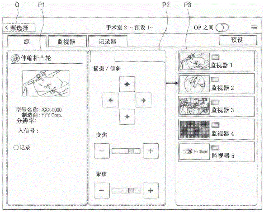
Fig. 11 shows an example of a source screen in the device control screen.
In the source screen shown in fig. 11, for example, a button (O shown in fig. 11) is provided for causing the screen to transition to a device selection screen that selects "source" in the device category selection tab. The user can select another device again in the device selection screen by operating the above-described button (O shown in fig. 11).
Further, the source screen shown in fig. 11 includes a device pane P1, a control pane P2, and a connection pane P3 from the left side in the display screen.
In the device pane P1 shown in fig. 11, information of a device corresponding to the device selection button (O3 shown in fig. 2) selected in the device selection screen in which "source" is selected in the device selection tab is displayed. Here, the device pane P1 shown in fig. 11 corresponds to an example of the first display area according to the present embodiment.
Fig. 12 shows an example of the configuration of the device pane P1. The device pane P1 includes, for example, an icon (O1 shown in fig. 12), a device name display (O2 shown in fig. 12), a thumbnail image (O3 shown in fig. 12), an attribute display (O4 shown in fig. 12), and a status display (O5 shown in fig. 12).
The icon (O1 shown in fig. 12) is an icon showing the type of the device.
The device name display (O2 shown in fig. 12) indicates the name of the device. An area of the device name display (O2 shown in fig. 12) is set to extend over the width of the device pane P1 so that, for example, a long device name can be displayed.
The thumbnail image (O3 shown in fig. 12) represents an image output from a device as an input source.
Here, although an example of the thumbnail image may include a still image, the thumbnail image may be a moving image. As described above, the thumbnail image according to the present embodiment may be updated regularly or irregularly. In the case of updating the thumbnail image, the latest image output from the input source may be reflected in the thumbnail image.
Further, for example, in the case of adjusting parameters of the device as an input source or the like in the control pane P2 of the device control screen, an image output from the input source after the adjustment of the parameters is reflected in the thumbnail image.
Further, in a case where the thumbnail image cannot be acquired, display as shown in B of fig. 5 or C of fig. 5 may be performed in the area for the thumbnail image.
The attribute display (O4 shown in fig. 12) represents, for example, information acquired from the device. Fig. 12 shows an example of displaying model names and manufacturers.
The status display (O5 shown in fig. 12) indicates the status of the device, for example, error display and operation status.
Referring again to fig. 11, an example of a source screen among the device control screens will be described. In the control pane P2 shown in fig. 11, objects for controlling the devices indicated in the device pane P1 are displayed. Here, the control pane P2 shown in fig. 11 corresponds to an example of the third display area according to the present embodiment. Further, since the device pane P1 corresponds to an example of the first display example according to the present embodiment, it can be said that the control pane P2 shown in fig. 11 is a display area in which an object for controlling the input source apparatus 200 is to be displayed.
Fig. 13 shows an example of the configuration of the control pane P2. The control pane P2 includes, for example, a control tab (O1 shown in fig. 13) and a parameter editing area (O2 shown in fig. 13).
The control label (O1 shown in fig. 13) is a label for each control category. Although fig. 11 shows an example in which one control tab is provided in the control pane P2, a plurality of control tabs may be provided.
In the parameter editing region (O2 shown in fig. 13), an object for operating the device indicated in the device pane P1 and an object for adjusting a parameter of the device indicated in the device pane P1 are displayed. In the parameter editing area (O2 shown in fig. 13) shown in fig. 13, an example is shown in which buttons for performing a panning operation and a tilting operation, an adjustment button and an adjustment slider for adjusting the amount of zooming, and an adjustment button and an adjustment slider for adjusting the amount of focusing are provided.
Note that in the case where the entire object cannot be displayed within the parameter editing area (O2 shown in fig. 13), the object may be scroll-displayed. Further, the current zoom amount, the current focus amount, and the like may be displayed numerically in the parameter editing area (O2 shown in fig. 13). Also, items to be displayed in the parameter editing area (O2 shown in fig. 13) may differ according to the type of device indicated in the device pane P1.
Referring again to fig. 11, an example of a source screen among the device control screens will be described. In the connection pane P3 shown in fig. 11, an object related to the output destination apparatus 300 is displayed, and at the object apparatus 300, an image output from the device indicated in the device pane P1 may be displayed. Here, the connection pane P3 shown in fig. 11 corresponds to an example of the second display area according to the present embodiment. Further, since the device pane P1 corresponds to an example of the first display area according to the present embodiment, it can be said that the connection pane P3 shown in fig. 11 is a display area in which an object related to the output destination apparatus 300 that can display an image of the input source apparatus 200 is to be displayed.
Fig. 14 shows an example of the configuration of the connection pane P3. The connection pane P3 includes displays such as a connection destination list (O1 shown in fig. 14) and a connection display (O2 shown in fig. 14).
The display of the connection destination list (O1 shown in fig. 14) represents a list of output destination apparatuses 300 that can display images output from the device indicated in the device pane P1. Examples of the output destination device 300 displayed in the display of the connection destination list (O1 shown in fig. 14) may include, for example, the output destination device 300 in which normal connection with the equipment indicated in the equipment pane P1 is ensured when the medical control system 1000 is built (or updated).
Further, the display of the connection destination list (O1 shown in fig. 14) includes, for example, "thumbnail image corresponding to the image displayed at the output destination apparatus 300", "icon indicating the output destination apparatus 300", and "device name display of the output destination apparatus 300".
Here, although an example of the thumbnail image may include a still image, the thumbnail image may be a moving image. As described above, the thumbnail image according to the present embodiment may be updated regularly or irregularly. In the case of updating the thumbnail image, the image newly input to the output destination device 300 may be reflected in the thumbnail image. Further, for example, in the case where parameters of the input source apparatus 200 and the like are adjusted in the control pane P2 of the device control screen shown in fig. 13, the image output from the input source apparatus 200 after the parameters are adjusted is reflected in the thumbnail image corresponding to the output destination apparatus 300 displaying the image output from the input source apparatus 200.
Further, in a case where the thumbnail image cannot be acquired, display as shown in B of fig. 5 or C of fig. 5 may be performed in the area for the thumbnail image.
The medical control apparatus 100 can display a thumbnail image of an image displayed on the display screen of the output destination in the connection pane P3 corresponding to the second display area as display of a connection destination list (O114 in fig. 1) shown in fig. 14, for example.
The connection display (O2 shown in fig. 14) represents the output destination device 300 selected by the user's operation on the connection pane P3.
Fig. 14 shows an example of the output destination device 300 indicated by an arrow to be selected. Note that the method for specifying the selected output destination device 300 is not limited to the example shown in fig. 14. Further, in a case where a plurality of output destination devices 300 are selected by a user operation for the connection pane P3, a plurality of types of connection displays are displayed in the connection pane P3.
Here, examples of the user operation for the connection pane P3 may include, for example, the following examples. Note that, needless to say, the example of the user operation for the connection pane P3 is not limited to the following example.
Operation of the touch connection pane P3 (in the case where the display device of the display target apparatus 500 is a touch panel)
Operation using an operation means such as a physical button or an external operation means such as a remote controller provided at the display target apparatus 500
The medical control apparatus 100 causes the designation of the output destination apparatus 300 in which the input source apparatus 200 is displayed to be selected by an operation on the second display area based on an operation on the connection pane P3 corresponding to the second display area, for example, as a connection display shown in fig. 14 (O2 shown in fig. 14).
Note that the source screen in the device control screen is not limited to the example shown in fig. 11.
Fig. 15 shows an example of an image output from the device indicated in the device pane P1.
There may be the following: the images output from the device indicated in the device pane P1 include, for example, images having a higher resolution than an image having a 2K resolution or images having a High Definition (HD) resolution, such as an image having a 4K resolution and an image having an 8K resolution.
Here, as described above, in the case where the image to be output by the apparatus indicated in the apparatus pane P1 is an image with high resolution, it is assumed that "a user such as a healthcare professional desires to display an image corresponding to the part of the image shown in a of fig. 15 at a different output destination device 300, for example, as shown in B of fig. 15 and C of fig. 15".
Accordingly, the source screen among the device control screens may be one that enables an image corresponding to a part of the image to be displayed on a different output destination apparatus 300 based on a user operation. For example, by causing an image corresponding to a part of an image to be displayed on a different output destination device 300, "an image obtained by changing the angle of view of an image of one input source device 200 may be caused to be displayed on a different output destination device 300".
Fig. 16 shows another example of a source screen in the device control screen.
Although the configuration of the source screen shown in fig. 16 is basically similar to that of the signal source screen shown in fig. 11, the difference is that "the output destination apparatus 300" to display an image corresponding to a part of an image output from the device indicated in the device pane P1 is specified.
For example, in the case where a part of a thumbnail image is selected as shown by O1 and O2 in fig. 16 by a user operation for the device pane P1 and the output destination apparatus 300 is selected by a user operation for the connection pane P3, the output destination apparatus 300 on which an image of the selected part of the thumbnail image is to be displayed is further specified as shown by O3 and O4 in fig. 16.
Here, examples of the user operation for the device pane P1 may include, for example, the following examples. Note that, needless to say, the example of the user operation on the device pane P1 is not limited to the following example.
An operation that can select an area on the display screen, for example, a zoom operation for a thumbnail image of the device pane P1 (in the case where the display device of the display target apparatus 500 is a touch panel)
Operation using an operation means such as a physical button or an external operation means such as a remote controller provided at the display target apparatus 500
The medical control apparatus 100 may also cause "designation of an output destination apparatus 300 in which an image corresponding to a part of the image of the input source apparatus 200 selected by a user operation on the device pane P1 is displayed and selected by an operation on the device pane P3" to be based on an operation with respect to the device pane P1 corresponding to the first display area and an operation with respect to the connection pane P3 corresponding to the second display area, for example, as O1 to O4 shown in fig. 16.
(II-2) second example of the device control screen: monitor picture
Fig. 17 and 18 are explanatory diagrams for explaining a display example in the medical control system 1000 to which the control method according to the present embodiment is applied. Each of fig. 17 and 18 shows the entire device control screen or a part of the device control screen displayed on the display screen of the display target apparatus 500.
Next, with reference to fig. 17 and 18, a second example of the apparatus control screen is described as appropriate. Here, the second example of the apparatus control screen corresponds to "a display example in a case where the first display region and the third display region are displayed in one screen".
Fig. 17 shows an example of a monitor screen in the device control screen.
The monitor screen shown in fig. 17 includes a connection pane P3, a device pane P1, and a control pane P2 from the left side of the display screen.
In the connection pane P3 shown in fig. 17, an object related to the input source apparatus 200 is displayed, which can be displayed by the output destination apparatus 300 selected in the device selection screen of selecting "monitor" in the device category selection tab. Here, the connection pane P3 shown in fig. 17 corresponds to an example of the first display area according to the present embodiment.
Fig. 17 shows an example of displaying a list of objects respectively related to the input source devices 200 in the connection pane P3. Examples of the object related to the input source apparatus 200 may include, for example, a thumbnail image, an icon, and a device name display, as in the case of the display of the connection destination list (O1 shown in fig. 14) shown in fig. 14.
Further, examples of the input source apparatus 200 displayed in the connection pane P3 may include, for example, the input source apparatus 200, which is ensured to be normally connected with the equipment indicated in the equipment pane P1 when the medical control system 1000 is built (or updated).
In the device pane P1 shown in fig. 17, information of a device corresponding to the device selection button selected in the device selection screen in which "monitor" is selected in the device type selection tab is displayed. Here, the configuration of the device pane P1 shown in fig. 17 is similar to that of the device pane P1 shown in fig. 12.
In the control pane P2 shown in fig. 17, objects for controlling the devices indicated in the device pane P1 are displayed. Here, the control pane P2 shown in fig. 17 corresponds to an example of the third display area according to the present embodiment. Further, the device indicated in the device pane P1 is the output destination apparatus 300 selected in the device selection screen in which "monitor" is selected in the device category selection tab. Therefore, it can be said that the control pane P2 shown in fig. 17 is a display area to display an object for controlling the output destination device 300.
Examples of objects displayed in the control pane P2 of the monitor screen among the device control screens for controlling the device indicated in the device pane P1 may include the following examples.
The button denoted "swap" in fig. 17: in the case where the device indicated in the device pane P1 has a PinP function (a function of allowing a plurality of display areas in which images can be independently displayed to be provided in one screen), a button for switching between the main display area and the sub display area
The button denoted "flip" in fig. 17: button for controlling display direction in device indicated in device pane P1
An adjustment button denoted "contrast" in fig. 17: button for adjusting contrast in a device indicated in a device pane P1
Adjustment buttons denoted "color" in fig. 17: buttons for adjusting RGB brightness, hue or balance in a device indicated in device pane P1
The button denoted "2D/3D mode" in fig. 17: a button for controlling switching of a display mode associated with the stereoscopic view in the device indicated in the device pane P1.
Note that the object displayed in the control pane P2 for controlling the device indicated in the device pane P1 in the monitor screen among the device control screens is not limited to the above-described example.
For example, in a case where the device indicated in the device pane P1 has a PinP function, an object for changing the configuration of a display area in the PinP function may be further displayed in the control pane P2 of the monitor screen of the device control screen. Note that an object for changing the display area configuration in the PinP function may also be displayed in another pane (e.g., the device pane P1). In the case where an object for changing the configuration of a display area in the PinP function is displayed in a pane other than the control pane P2 shown in fig. 17, the pane displaying the object for changing the configuration of a display area in the PinP function functions as the third display area according to the present embodiment.
Examples of the configuration of the display area in the PinP function may include, for example, examples shown in a to D of fig. 18. In fig. 18 a to 18D, display regions denoted by "a", "b", "c", and "D" correspond to display regions in the PinP function.
In the case where the device indicated in the device pane P1 corresponding to the output destination apparatus 300 has the PinP function, the medical control apparatus 100 may cause "an object for controlling display in one or more display regions associated with PinP in the output destination apparatus 300 to be displayed in the control pane P2 corresponding to the third display region", for example, as a button represented as "swap" in fig. 17.
Further, objects displayed in the control pane P2 of the monitor screen among the device control screens for controlling the device indicated in the device pane P1 may be different according to the type of the device indicated in the device pane P1.
For example, in the case where the device indicated in the device pane P1 does not have the PinP function, it is not necessary to display the button indicated as "flip" in fig. 17.
(II-3) third example of the device control screen: recorder picture
Fig. 19A and 19B are explanatory diagrams for explaining a display example of the medical control system 1000 to which the control method according to the present embodiment is applied. Fig. 19A and 19B each show an entire device control screen displayed in the display screen of the display target apparatus 500. Switching is performed between the device control screen shown in fig. 19A and the device control screen shown in fig. 19B by a user operation.
Next, with reference to fig. 19A and 19B, a third example of the apparatus control screen is described as appropriate. Here, the device control screen shown in fig. 19A corresponds to "a display example in the case where the first display region and the third display region are displayed in one screen". Further, the third example of the apparatus control screen shown in fig. 19B corresponds to "a display example in a case where the second display region and the third display region are displayed in one screen".
Fig. 19A shows an example of a recorder screen in the device control screen.
The recorder screen shown in fig. 19A includes, from the left side of the display screen, in a manner similar to the monitor screen shown in fig. 17: a connection pane P3, a device pane P1, and a control pane P2.
In the connection pane P3 shown in fig. 19A, an object related to the input source apparatus 200 is displayed, which can output an image signal by the apparatus 400 selected in the device selection screen in which "recorder" is selected in the device selection tab. Here, the connection pane P3 shown in fig. 19A corresponds to an example of the first display area according to the present embodiment.
Fig. 19A shows an example of displaying a list of objects related to the input source device 200 in the connection pane P3, as in the case of fig. 17. Further, an example of the input source device 200 displayed in the connection pane P3 shown in fig. 19A may include: such as the input source device 200, ensures its normal connection with the equipment indicated in the equipment pane P1 when the medical control system 1000 is built (or updated).
In the device pane P1 shown in fig. 19A, information of a device corresponding to the device selection button selected in the device selection screen in which "monitor" is selected in the device type selection tab is displayed. Here, the configuration of the device pane P1 shown in fig. 19A is similar to that of the device pane P1 shown in fig. 12, for example.
In the control pane P2 shown in fig. 19A, an object for controlling a device indicated in the device pane P1 is displayed. Here, the control pane P2 shown in fig. 19A corresponds to an example of the third display area according to the present embodiment. Further, the device indicated in the device pane P1 is the apparatus 400 selected in the device selection screen in which "recorder" is selected in the device category selection tab. Therefore, it can be said that the control pane P2 shown in fig. 19A is a display area in which an object for controlling the device 400 is to be displayed.
Examples of objects displayed in the control pane P2 of the recorder screen among the device control screens for controlling the device indicated in the device pane P1 may include the following examples. Note that, needless to say, the example of the object displayed in the control pane P2 of the recorder screen of the device control screen for controlling the device shown in the device pane P1 is not limited to the following example.
A record button (O1 shown in FIG. 19A) for starting recording of image data in the recording medium
A stop button (O2 shown in FIG. 19A) for stopping the processing being executed
A pause button (O3 shown in FIG. 19A) for pausing the executing process
A reproduction button (O4 shown in FIG. 19A) for starting reproduction of image data stored in the recording medium
Rewind button for rewinding an image being reproduced (O5 shown in FIG. 19A)
A fast forward button (O6 shown in FIG. 19A) for fast forwarding an image being reproduced
According to the device control screen shown in fig. 19A, recording of image data in the device indicated in the device pane P1 can be controlled from the input source apparatus 200 selected by a user operation on the connection pane P3, for example.
Fig. 19B shows another example of the recorder screen in the device control screen.
The recorder screen shown in fig. 19B includes a device pane P1, a control pane P2, and a connection pane P4 from the left side of the display screen.
The device pane P1 shown in fig. 19B and the control pane P2 shown in fig. 19B are the same as the device pane P1 shown in fig. 19A and the control pane P2 shown in fig. 19B, respectively. Here, the control pane P2 shown in fig. 19B corresponds to an example of the third display area according to the present embodiment. Further, the device indicated in the device pane P1 is the apparatus 400 selected in the device selection screen that selects "recorder" in the device category selection tab. Therefore, it can be said that the control pane P2 shown in fig. 19B is a display area in which an object for controlling the device 400 is to be displayed.
In the connection pane P4 shown in fig. 19B, as in the case of the connection pane P3 shown in fig. 11 and 14, an object related to the output destination apparatus 300 is displayed, and in the output destination apparatus 300, an image output from the device indicated in the device pane P1 may be displayed. Here, the connection pane P4 shown in fig. 19B corresponds to an example of the second display area according to the present embodiment.
As described above, the connection pane P4 shown in fig. 19B corresponds to the second display region according to the present embodiment, as in the case of the connection pane P3 shown in fig. 11 and 14. Therefore, as in the case of the connection pane P3 shown in fig. 11 and 14, the medical control apparatus 100 can cause a thumbnail image of an image displayed on the display screen of the output destination to be displayed in the connection pane P4 corresponding to the second display area.
According to the device control screen shown in fig. 19B, for example, an image reproduced in the device indicated in the device pane P1 can be caused to be displayed on the output destination apparatus 300 selected by a user operation with respect to the connection pane P4.
Here, among the apparatuses 400 selected in the device selection screen in which "recorder" is selected in the device category selection tab, there may be apparatuses having an image recording function and an image reproducing function, that is, apparatuses serving as an output destination and an input source.
In order to control the apparatus 400 serving as the output destination and the input source as described above, one of the device control screen shown in fig. 19A and the device control screen shown in fig. 19B is insufficient.
Here, for example, if the connection pane P4 shown in fig. 19B is further displayed on the device control screen shown in fig. 19A, the apparatus 400 serving as the output destination and the input source as described above can be sufficiently controlled. However, in a case where the size or resolution of the display screen is not sufficiently large, for example, in a case where the display target apparatus 500 is a tablet type apparatus, there is a possibility that: by further displaying a connection pane P4 shown in fig. 19B in the device control screen shown in fig. 19A, visibility is reduced.
Therefore, the medical control apparatus 100 switches and displays between the device control screen illustrated in fig. 19A and the device control screen illustrated in fig. 19B, for example, based on a user operation.
Here, examples of the user operation for switching the display of the apparatus control screen may include, for example, the following examples. Note that it goes without saying that examples of user operations for switching the display of the apparatus control screen are not limited to the following examples.
An operation that can switch the display of the display screen, for example, an operation of sliding the display screen (in the case where the display device of the display target apparatus 500 is a touch panel)
Operation using an operation means such as a physical button or an external operation means such as a remote controller provided at the display target apparatus 500
By causing the screen to be switched and displayed between the device control screen shown in fig. 19A and the device control screen shown in fig. 19B by the medical control apparatus 100, it is possible to prevent a decrease in visibility and sufficiently control the apparatus 400 serving as the output destination and the input source as described above.
【3】 Example of effects provided by the control method according to the present embodiment being used
The control processing associated with the control method according to the present embodiment is executed by the medical control apparatus 100, for example, providing the following effects. Note that, needless to say, the effect provided by the control method according to the present embodiment being used is not limited to the following effect.
For example, with the apparatus control screens shown in fig. 11, 17, 19A, and 19B being used, since switching of images and control of devices can be performed in one screen, a user can work efficiently.
For example, as shown in a connection pane P3 in fig. 11, a connection pane P3 in fig. 17, a connection pane P3 in fig. 19A, and a connection pane P4 in fig. 19B, since only an apparatus that can switch an image is displayed in the device control screen, an erroneous operation by the user can be prevented.
In addition, at a device in which a signal source and an output destination as a recorder (an example of the device 400) are changed according to a process to be performed (a process corresponding to a usage purpose of the recorder), for example, as described with reference to fig. 19A and 19B, a user can perform a common operation by switching modes by a user operation such as a slide operation.
For example, as described with reference to fig. 15 and 16, a plurality of images obtained by changing the angle of view of one image may be output to respectively different monitors (examples of output destinations).
(medical control apparatus according to the present embodiment)
Next, an example of a configuration of the medical control apparatus according to the present embodiment that can execute the above-described processing associated with the control method according to the present embodiment will be described.
Fig. 20 is a block diagram showing an example of the configuration of the medical control apparatus 100 according to the present embodiment. The medical control apparatus 100 includes, for example, a communication unit 102 and a control unit 104.
Further, the medical control apparatus 100 may include, for example, a read only memory (ROM, not shown), a random access memory (RAM, not shown), a storage unit (not shown), an operation unit (not shown) that can be operated by a user, a display unit (not shown) that displays various screens on a display screen, and the like. The medical control apparatus 100 connects the above components to a bus as a data transmission path, for example.
The ROM (not shown) stores control data such as programs and operation parameters to be used by the control unit 104. A RAM (not shown) temporarily stores programs to be executed by the control unit 104.
The storage unit (not shown) stores various data such as data associated with the control method and the application program according to the present embodiment. Here, an example of the storage unit (not shown) may include, for example, a recording medium such as a nonvolatile memory. Further, the storage unit (not shown) may be detachable from the medical control apparatus 100, for example.
Examples of the operation unit (not shown) may include, for example, an operation input device which will be described later. Further, examples of the display unit (not shown) may include a display device which will be described later.
Hardware configuration example of the medical control apparatus 100
Fig. 21 is an explanatory diagram showing an example of the hardware configuration of the medical control apparatus 100 according to the present embodiment. The medical control apparatus 100 includes, for example, an MPU 150, a ROM 152, a RAM 154, a recording medium 156, an input/output interface 158, an operation input device 160, a display device 162, and a communication interface 164. The medical control apparatus 100 connects each component to a bus 166 as a data transmission path, for example.
The MPU 150 is configured of, for example, one or more processors configured with an arithmetic circuit such as an MPU, various processing circuits, and the like, and functions as a control unit (not shown) that controls the entire medical control apparatus 100. Further, the MPU 150 functions as, for example, the processing unit 110 in the medical control apparatus 100. Note that the processing unit 110 may be configured with dedicated (or general purpose) circuitry (e.g., a processor separate from the MPU 150) that may implement the processing at the processing unit 110.
The ROM 152 stores control data such as programs and operation parameters to be used by the MPU 150. The RAM 154 temporarily stores programs and the like to be executed by the MPU 150.
The recording medium 156 serving as a storage unit (not shown) stores, for example, data associated with the control method according to the present embodiment and various data such as various application programs. Here, examples of the recording medium 156 may include, for example, a magnetic recording medium such as a hard disk and a nonvolatile memory such as a flash memory. Further, the recording medium 156 is detachable from the medical control apparatus 100.
The input/output interface 158 connects, for example, an operation input device 160 and a display device 162. The operation input device 160 functions as an operation unit (not shown), and the display device 162 functions as a display unit (not shown). Here, examples of the input/output interface 158 may include, for example, a Universal Serial Bus (USB) terminal, a Digital Visual Interface (DVI) terminal, a high-definition multimedia interface (HDMI) (registered trademark) terminal, various processing circuits, and the like.
Further, an operation input device 160 is provided on the medical control apparatus 100, for example, and is connected to the input/output interface 158 within the medical control apparatus 100. Examples of the operation input device 160 may include, for example, a button, a direction key, a rotary selector such as a jog dial (jog dial), a combination thereof, and the like.
Further, a display device 162 is provided on the medical control apparatus 100, for example, and is connected to the input/output interface 158 within the medical control apparatus 100. Examples of the display device 162 may include, for example, a liquid crystal monitor, an organic Electroluminescence (EL) monitor, an Organic Light Emitting Diode (OLED) monitor, and the like.
Note that, needless to say, the input/output interface 158 may be connected to external devices such as an external operation input device (e.g., a keyboard and a mouse) and an external display device of the medical control apparatus 100. Further, the display device 162 may be a device such as a touch panel which can perform display and allow a user operation.
The communication interface 164 is a communication means provided in the medical control apparatus 100. The communication interface 164 functions as, for example, a communication unit (not shown) for communicating with each of one or more external apparatuses constituting the medical control system 1000, such as the input source apparatus 200, the output destination apparatus 300, the apparatus 400, the display target apparatus 500, and the other apparatuses 600A and 600B, in a wireless or wired manner through a network (or directly). Further, the communication interface 164 may function, for example, to communicate with an external device other than the devices (e.g., servers) constituting the medical control system 1000 in a wireless or wired manner.
Here, examples of the communication interface 164 may include, for example, a communication antenna and a Radio Frequency (RF) circuit (wireless communication), an IEEE802.15.1 port and a transmission/reception circuit (wireless communication), an IEEE802.11 port and a transmission/reception circuit (wireless communication), a Local Area Network (LAN) terminal and a transmission/reception circuit (wired communication), and the like.
The medical control apparatus 100 performs processing corresponding to the control method according to the present embodiment, for example, using the configuration shown in fig. 21. Note that the hardware configuration of the medical control apparatus according to the present embodiment is not limited to the configuration shown in fig. 21.
For example, in the case where the medical control apparatus 100 communicates with an external apparatus or the like via a connected external communication device, the communication interface 164 does not have to be provided. Further, communication interface 164 may be configured to enable communication with one or more external devices using a variety of communication schemes.
Further, the medical control apparatus 100 may employ, for example, a configuration that does not include one or more of the recording medium 156, the operation input device 160, and the display device 162.
In addition, for example, a part or all of the configuration shown in fig. 21 (or the configuration according to the modified example) may be implemented with one or more Integrated Circuits (ICs).
Referring again to fig. 20, an example of the configuration of the medical control apparatus 100 will be described. The communication unit 102, which is a communication means provided in the medical control apparatus 100, communicates with each of one or more external apparatuses constituting the medical control system 1000, such as the input source apparatus 200, the output destination apparatus 300, the apparatus 400, the display target apparatus 500, and the other apparatuses 600A and 600B, in a wireless or wired manner. The communication unit 102 may communicate with an external device other than the devices (e.g., servers) constituting the medical control system 1000 in a wireless or wired manner.
Here, although examples of the communication unit 102 may include, for example, a communication antenna and an RF circuit, a LAN terminal, a transmission/reception circuit, and the like, the configuration of the communication unit 102 is not limited to the above-described configuration. For example, the communication unit 102 may adopt a configuration supporting any standard capable of communication (e.g., a USB terminal and a transmission/reception circuit, etc.) or any configuration capable of communicating with an external device via a network. Further, the communication unit 102 may be configured to be able to communicate with one or more external devices using a variety of communication schemes.
The entire medical control apparatus 100 is controlled by a control unit 104 configured of one or more processors configured with an arithmetic circuit such as an MPU, various processing circuits, and the like, for example. Further, the control unit 104 includes, for example, a processing unit 110, and functions to guide processing associated with the control method according to the present embodiment.
The processing unit 110 functions to guide the control processing according to the present embodiment. The processing unit 110 causes a first display area in which an object related to an input source is displayed and/or a second display area in which an object related to an output destination is displayed and a third display area for controlling the input source or the output destination to be displayed in one screen.
As a specific example, the processing unit 110 causes, for example, the above-described device control screen to be displayed on the display screen of the display target apparatus 500, as illustrated in fig. 11, 17, 19A, and 19B.
Further, the processing unit 110 may also cause other screens, for example, the device selection screens described with reference to fig. 2 to 9, or the like, to be displayed on the display screen of the display target apparatus 500.
Further, for example, the processing unit 110 may execute processing in response to a user operation performed on a screen (e.g., a device control screen) displayed at the display target apparatus 500 or a screen (e.g., a device selection screen) displayed on the display target apparatus 500 by the control processing according to the present embodiment. Examples of the above-described processing in response to the user operation may include, for example, "processing of causing a screen to transition to a device control screen corresponding to an operation in response to an operation with respect to the device selection screen", "processing of connecting the input source apparatus 200 and the output destination apparatus 300 (or the apparatus 400) by controlling various switches shown in fig. 1 in response to an operation with respect to the device control screen", and the like.
By the control unit 104 including, for example, the processing unit 110, the control unit 104 guides processing associated with the control method according to the present embodiment.
The medical control apparatus 100 executes processing (for example, the above-described control processing) according to the control method of the present embodiment using, for example, the configuration shown in fig. 20.
Therefore, the medical control apparatus 100 can improve the operability of the user with the configuration shown in fig. 20, for example.
Further, the medical control apparatus 100 can provide the effect provided by the processing associated with the control method according to the present embodiment being performed with the configuration shown in fig. 20, for example.
Further, the medical control system 1000 that can improve the operability for the user is realized by the medical control apparatus 100 having the configuration shown in fig. 20, for example.
Note that the configuration of the medical control apparatus according to the present embodiment is not limited to the configuration shown in fig. 20.
For example, the medical control apparatus according to the present embodiment may include the processing unit 110 shown in fig. 20 separately from the control unit 104 (for example, the processing unit 110 may be implemented with another processing circuit).
Further, as described above, the above-described control processing is processing divided from the processing associated with the control method according to the present embodiment for the sake of convenience. Therefore, the configuration for realizing the processing associated with the control method according to the present embodiment is not limited to the configuration shown in fig. 20, and may be a configuration according to the manner of division of the processing associated with the control method according to the present embodiment.
Further, in the case of communicating with an external apparatus through an external communication device having a function and configuration similar to those of the communication unit 102, the medical control apparatus according to the present embodiment does not necessarily include the communication unit 102.
Although the medical control apparatus has been described above as the present embodiment, the present embodiment is not limited to such an embodiment. The present embodiment can be applied to various apparatuses that can execute processing associated with the control method according to the present embodiment, such as a computer (e.g., PC), a server and an OR controller, a tablet-type apparatus, and a communication device (e.g., smartphone). Furthermore, the present embodiment may be applied to, for example, a processing IC that may be incorporated into a device as described above.
(procedure according to the present embodiment)
By executing a program for causing a computer to function as the medical control apparatus according to the present embodiment (a program that can execute processing associated with the control method according to the present embodiment (e.g., the above-described control processing) by a processor or the like on the computer), the operability of the user can be improved.
Further, by executing a program for causing a computer to function as the medical control apparatus according to the present embodiment by a processor or the like on the computer, it is possible to provide the effects provided by the above-described processing associated with the control method according to the present embodiment.
The preferred embodiments of the present disclosure are described above with reference to the drawings, but the present disclosure is not limited to the above examples. Those skilled in the art can find various changes and modifications within the scope of the appended claims, and it should be understood that they will naturally fall within the technical scope of the present disclosure.
For example, although the configuration of a program (computer program) for causing a computer to function as the medical control apparatus according to the present embodiment has been described above, the present embodiment may also provide a recording medium in which the above-described program is stored.
The above-described configuration is one example of the present embodiment, and naturally falls within the technical scope of the present disclosure.
Further, the effects described in the present specification are merely illustrative or exemplary effects, and are not restrictive. That is, other effects apparent to those skilled in the art can be achieved from the description of the present specification in accordance with the techniques of the present disclosure, with or instead of the above-described effects.
In addition, the present technology can also be configured as follows.
(1) A medical control device, comprising:
a processing unit configured to cause one or both of a first display area in which an object related to an input source of an image is displayed and a second display area in which an object related to an output destination of an image is displayed and a third display area in which an object for controlling the input source or the output destination is displayed to be displayed in one screen.
(2) The medical control apparatus according to (1),
wherein, in a case where both the first display area and the second display area and the third display area are displayed in one screen,
the processing unit
Displaying an object related to the output destination capable of displaying the image of the input source in the second display area, and
displaying an object for controlling the input source in the third display area.
(3) The medical control apparatus according to (2),
wherein the processing unit specifies the output destination to display the image of the input source based on an operation on the second display area, the output destination being selected by the operation on the second display area.
(4) The medical control apparatus according to (3),
wherein the processing unit further specifies an output destination of an image corresponding to a part of the image of the input source selected by the operation on the first display area based on the operation on the first display area and the operation on the second display area, the output destination being selected by the operation on the second display area.
(5) The medical control apparatus according to any one of (1) to (4),
wherein, in a case where the first display region and the third display region are displayed in one screen,
the processing unit makes
The first display area displays an object related to the input source that enables displaying an image at the output destination or an object related to the input source that enables recording an image at the output destination, and
an object for controlling the output destination is displayed in the third display area.
(6) The medical control apparatus according to (5),
wherein in a case where the output destination has a function capable of providing a plurality of display areas in one screen, the plurality of display areas being capable of independently displaying an image,
the processing unit causes an object for controlling display in one or more of the display areas of the output destination to be displayed in the third display area.
(7) The medical control apparatus according to any one of (1) to (6),
wherein, in a case where the second display region and the third display region are displayed in one screen,
the processing unit makes
Displaying an object related to an output destination capable of displaying an image of the input destination in the second display area; and is
And displaying an object for controlling the input source in the third display area.
(8) The medical control apparatus according to any one of (2) to (4) and (6),
wherein the processing unit displays a thumbnail image of an image displayed on the display screen of the output destination in the second display area.
(9) The medical control apparatus according to (8),
wherein the thumbnail images are moving images.
(10) A control method performed by a medical control apparatus, the method comprising:
a step of displaying one or both of a first display area in which an object related to an input source of an image is displayed, a second display area in which an object related to an output destination of an image is displayed, and a third display area in which an object for controlling the input source or the output destination is displayed, in one screen.
(11) A program for causing a computer to execute functions of: a first display area in which an object related to an input source of an image is displayed, a second display area in which an object related to an output destination of an image is displayed, and a third display area in which an object for controlling the input source or the output destination is displayed are displayed in one screen.
(12) A medical control system, comprising:
a device serving as an input source of an image;
a device serving as an output destination of an image; and
the medical control device is provided with a medical control device,
wherein the medical control apparatus includes a processing unit configured to cause one or both of a first display area in which an object related to the input source is displayed and a second display area in which an object related to the output destination is displayed, and a third display area in which an object for controlling the input source or the output destination is displayed to be displayed in one screen.
List of reference numerals
100 medical control device 102 communication unit 104 control unit 110 processing unit
200 input source device 300 output destination device 400 device 500 display target device
600 other apparatus 1000 medical control system.
Claims (10)
Priority Applications (1)
| Application Number | Priority Date | Filing Date | Title |
|---|---|---|---|
| CN202110496002.4A CN113384359B (en) | 2015-10-02 | 2016-08-16 | Medical control device, control method, program, and medical control system |
Applications Claiming Priority (5)
| Application Number | Priority Date | Filing Date | Title |
|---|---|---|---|
| JP2015196415 | 2015-10-02 | ||
| JP2015-196415 | 2015-10-02 | ||
| PCT/JP2016/073901 WO2017056762A1 (en) | 2015-10-02 | 2016-08-16 | Medical control device, control method, program and medical control system |
| CN202110496002.4A CN113384359B (en) | 2015-10-02 | 2016-08-16 | Medical control device, control method, program, and medical control system |
| CN201680055980.2A CN108135669B (en) | 2015-10-02 | 2016-08-16 | Medical control equipment, control method, program, and medical control system |
Related Parent Applications (1)
| Application Number | Title | Priority Date | Filing Date |
|---|---|---|---|
| CN201680055980.2A Division CN108135669B (en) | 2015-10-02 | 2016-08-16 | Medical control equipment, control method, program, and medical control system |
Publications (2)
| Publication Number | Publication Date |
|---|---|
| CN113384359A true CN113384359A (en) | 2021-09-14 |
| CN113384359B CN113384359B (en) | 2024-08-20 |
Family
ID=58427418
Family Applications (3)
| Application Number | Title | Priority Date | Filing Date |
|---|---|---|---|
| CN202110496598.8A Pending CN113384360A (en) | 2015-10-02 | 2016-08-16 | Medical control apparatus, control method, program, and medical control system |
| CN202110496002.4A Active CN113384359B (en) | 2015-10-02 | 2016-08-16 | Medical control device, control method, program, and medical control system |
| CN201680055980.2A Active CN108135669B (en) | 2015-10-02 | 2016-08-16 | Medical control equipment, control method, program, and medical control system |
Family Applications Before (1)
| Application Number | Title | Priority Date | Filing Date |
|---|---|---|---|
| CN202110496598.8A Pending CN113384360A (en) | 2015-10-02 | 2016-08-16 | Medical control apparatus, control method, program, and medical control system |
Family Applications After (1)
| Application Number | Title | Priority Date | Filing Date |
|---|---|---|---|
| CN201680055980.2A Active CN108135669B (en) | 2015-10-02 | 2016-08-16 | Medical control equipment, control method, program, and medical control system |
Country Status (5)
| Country | Link |
|---|---|
| US (3) | US20180271613A1 (en) |
| EP (1) | EP3342365B1 (en) |
| JP (1) | JP6838554B2 (en) |
| CN (3) | CN113384360A (en) |
| WO (1) | WO2017056762A1 (en) |
Families Citing this family (12)
| Publication number | Priority date | Publication date | Assignee | Title |
|---|---|---|---|---|
| WO2017056762A1 (en) | 2015-10-02 | 2017-04-06 | ソニー株式会社 | Medical control device, control method, program and medical control system |
| EP3550825A4 (en) * | 2016-12-01 | 2020-05-13 | LG Electronics Inc. -1- | IMAGE DISPLAY DEVICE AND IMAGE DISPLAY SYSTEM INCLUDING THE SAME |
| US11896195B2 (en) | 2018-07-24 | 2024-02-13 | Sony Corporation | Distributed image processing system in operating theater |
| JP6440136B1 (en) * | 2018-09-06 | 2018-12-19 | 株式会社Medi Plus | Medical video switcher |
| CN116997289A (en) * | 2021-03-25 | 2023-11-03 | 索尼集团公司 | Operating room systems, image recording methods, procedures and medical information processing systems |
| USD1091560S1 (en) * | 2021-04-22 | 2025-09-02 | Google Llc | Display screen or portion thereof with graphical user interface |
| USD1091601S1 (en) * | 2021-04-22 | 2025-09-02 | Google Llc | Display screen or portion thereof with graphical user interface |
| USD1091561S1 (en) * | 2021-04-22 | 2025-09-02 | Google Llc | Display screen or portion thereof with graphical user interface |
| USD1091562S1 (en) * | 2021-04-22 | 2025-09-02 | Google Llc | Display screen or portion thereof with graphical user interface |
| US11694655B2 (en) * | 2021-05-20 | 2023-07-04 | Tcl China Star Optoelectronics Technology Co., Ltd. | Video play system, video play device, and video play method |
| JP7783720B2 (en) * | 2021-10-28 | 2025-12-10 | キヤノンメディカルシステムズ株式会社 | Modality control device and display control program |
| CN117935753A (en) * | 2024-01-22 | 2024-04-26 | 深圳市朗腾威视科技有限公司 | A multi-screen display system based on thunderbolt chip and control method thereof |
Citations (15)
| Publication number | Priority date | Publication date | Assignee | Title |
|---|---|---|---|---|
| JP2005110877A (en) * | 2003-10-06 | 2005-04-28 | Olympus Corp | Surgery support system |
| CN1702645A (en) * | 2004-05-24 | 2005-11-30 | 株式会社东芝 | Medical image display apparatus |
| US20060025679A1 (en) * | 2004-06-04 | 2006-02-02 | Viswanathan Raju R | User interface for remote control of medical devices |
| CN1832548A (en) * | 2005-03-09 | 2006-09-13 | 三星电子株式会社 | Display apparatus and control method thereof |
| US20070120550A1 (en) * | 2004-04-23 | 2007-05-31 | Olympus Corporation | Medical system control device |
| JP2008086665A (en) * | 2006-10-04 | 2008-04-17 | Olympus Medical Systems Corp | Medical image processing system |
| US20080122924A1 (en) * | 2006-06-21 | 2008-05-29 | Olympus Medical Systems Corp. | Technique image recording control system, technique image recording control method and operation system |
| US8069420B2 (en) * | 2004-12-29 | 2011-11-29 | Karl Storz Endoscopy-America, Inc. | System for controlling the communication of medical imaging data |
| CN103099676A (en) * | 2011-11-15 | 2013-05-15 | 三星电子株式会社 | Medical device and method for displaying medical image using the same |
| CN103153171A (en) * | 2010-08-30 | 2013-06-12 | 富士胶片株式会社 | Medical information display device, method and program |
| CN103142309A (en) * | 2005-10-20 | 2013-06-12 | 直观外科手术操作公司 | Auxiliary image display and manipulation on computer display in medical robotic system |
| CN103177183A (en) * | 2011-12-21 | 2013-06-26 | 三星电子株式会社 | Medical apparatus and image displaying method using the same |
| JP2014104099A (en) * | 2012-11-27 | 2014-06-09 | Hitachi Information & Control Solutions Ltd | Medical information display apparatus and medical information display program |
| CN103845071A (en) * | 2012-12-03 | 2014-06-11 | 三星电子株式会社 | Control apparatus and medical imaging apparatus having the same |
| CN104105442A (en) * | 2012-03-01 | 2014-10-15 | 株式会社日立医疗器械 | Medical image display device and medical image display method |
Family Cites Families (53)
| Publication number | Priority date | Publication date | Assignee | Title |
|---|---|---|---|---|
| JPS5034256B1 (en) | 1970-01-20 | 1975-11-07 | ||
| JP3012342B2 (en) | 1990-01-19 | 2000-02-21 | オリンパス光学工業株式会社 | Medical image display device |
| JP3012432B2 (en) | 1993-06-24 | 2000-02-21 | ヤンマー農機株式会社 | Stopping distance adjustment structure for following-type traveling vehicles |
| US5812125A (en) * | 1995-06-30 | 1998-09-22 | International Business Machines Corporation | Method and apparatus for selectively generating display images |
| JP2001000449A (en) * | 1999-06-22 | 2001-01-09 | Olympus Optical Co Ltd | Medical system |
| US6493036B1 (en) * | 1999-11-17 | 2002-12-10 | Teralogic, Inc. | System and method for scaling real time video |
| US20060064716A1 (en) * | 2000-07-24 | 2006-03-23 | Vivcom, Inc. | Techniques for navigating multiple video streams |
| JP2002125219A (en) * | 2000-10-17 | 2002-04-26 | Olympus Optical Co Ltd | System controller |
| GB2400254A (en) * | 2003-03-31 | 2004-10-06 | Sony Uk Ltd | Video processing |
| JP2004313341A (en) * | 2003-04-14 | 2004-11-11 | Olympus Corp | Medical device system |
| JP4081046B2 (en) | 2003-09-05 | 2008-04-23 | 松下電器産業株式会社 | Broadcast receiving antenna and television broadcast receiver |
| US7312764B2 (en) * | 2003-09-26 | 2007-12-25 | The General Electric Company | Methods and apparatus for displaying images on mixed monitor displays |
| JP2005245961A (en) * | 2004-03-08 | 2005-09-15 | Olympus Corp | Image processing apparatus |
| JP4207900B2 (en) * | 2004-12-22 | 2009-01-14 | ソニー株式会社 | Remote control system, remote commander, and remote control server |
| JP5160025B2 (en) * | 2005-04-14 | 2013-03-13 | オリンパスメディカルシステムズ株式会社 | Surgery system |
| US7843865B2 (en) * | 2005-12-08 | 2010-11-30 | Intel Corporation | System and method for controlling home network devices using multicast enabled remote controls |
| JP5034256B2 (en) * | 2006-02-11 | 2012-09-26 | 富士ゼロックス株式会社 | Conference room control system |
| US20070159457A1 (en) * | 2006-04-27 | 2007-07-12 | Thomas Arthur | Multiple-input selectable systems integrated display and control functions unit for electrophysiology and the like |
| US7927272B2 (en) * | 2006-08-04 | 2011-04-19 | Avantis Medical Systems, Inc. | Surgical port with embedded imaging device |
| US7567233B2 (en) * | 2006-09-06 | 2009-07-28 | Stereotaxis, Inc. | Global input device for multiple computer-controlled medical systems |
| US7871403B2 (en) * | 2008-02-26 | 2011-01-18 | Olympus Medical Systems Corp. | Medical support control system |
| DE102008017846A1 (en) * | 2008-04-08 | 2009-10-29 | Siemens Aktiengesellschaft | Method and user interface for the graphical representation of medical data |
| KR101557176B1 (en) * | 2008-05-02 | 2015-10-02 | 사반트 시스템즈 엘엘씨 | Touch sensitive video signal display for a programmable multimedia controller |
| US20090282437A1 (en) * | 2008-05-09 | 2009-11-12 | Tap.Tv | System and Method for Controlling Media at a Plurality of Output Devices |
| KR101012980B1 (en) * | 2009-03-16 | 2011-02-10 | 한국방송공사 | Hierarchical Broadcasting Device and Method |
| US9241062B2 (en) * | 2009-05-20 | 2016-01-19 | Citrix Systems, Inc. | Methods and systems for using external display devices with a mobile computing device |
| US20120182244A1 (en) * | 2010-06-11 | 2012-07-19 | Systemsone, Llc | Integrated Multi-Display with Remote Programming and Viewing Capability |
| US20120173281A1 (en) * | 2011-01-05 | 2012-07-05 | Dilella James M | Automated data entry and transcription system, especially for generation of medical reports by an attending physician |
| US9495511B2 (en) * | 2011-03-01 | 2016-11-15 | Covidien Lp | Remote monitoring systems and methods for medical devices |
| US20120189173A1 (en) * | 2011-01-26 | 2012-07-26 | Markowitz H Toby | Image display |
| US20120254933A1 (en) * | 2011-03-31 | 2012-10-04 | Hunt Electronic Co., Ltd. | Network video server and video control method thereof |
| US10039502B2 (en) * | 2011-04-12 | 2018-08-07 | Medtronic Ablation Frontiers Llc | Electrophysiological signal processing and utilization |
| US10714219B2 (en) * | 2011-04-28 | 2020-07-14 | Tiatros, Inc. | System and method for uploading and sharing medical images within trusted health-user communities |
| US9240002B2 (en) * | 2011-08-19 | 2016-01-19 | Hospira, Inc. | Systems and methods for a graphical interface including a graphical representation of medical data |
| JP5347089B1 (en) * | 2012-01-26 | 2013-11-20 | オリンパスメディカルシステムズ株式会社 | Medical information recording device |
| US8670816B2 (en) * | 2012-01-30 | 2014-03-11 | Inneroptic Technology, Inc. | Multiple medical device guidance |
| JP6165468B2 (en) * | 2012-03-05 | 2017-07-19 | 東芝メディカルシステムズ株式会社 | Medical image processing system |
| US9545192B2 (en) * | 2012-05-04 | 2017-01-17 | Given Imaging Ltd. | System and method for automatic navigation of a capsule based on image stream captured in-vivo |
| US9642606B2 (en) | 2012-06-27 | 2017-05-09 | Camplex, Inc. | Surgical visualization system |
| CN203195765U (en) * | 2012-12-20 | 2013-09-18 | 上海联影医疗科技有限公司 | Medical information display system |
| JP6415812B2 (en) * | 2012-12-25 | 2018-10-31 | キヤノンメディカルシステムズ株式会社 | Image observation apparatus, image observation method, and computer-readable recording medium |
| WO2014168128A1 (en) * | 2013-04-12 | 2014-10-16 | オリンパスメディカルシステムズ株式会社 | Endoscope system and operation method for endoscope system |
| KR102071579B1 (en) * | 2013-09-02 | 2020-01-30 | 삼성전자주식회사 | Method for providing services using screen mirroring and apparatus thereof |
| US9058375B2 (en) * | 2013-10-09 | 2015-06-16 | Smart Screen Networks, Inc. | Systems and methods for adding descriptive metadata to digital content |
| US10445465B2 (en) * | 2013-11-19 | 2019-10-15 | General Electric Company | System and method for efficient transmission of patient data |
| US11977998B2 (en) * | 2014-05-15 | 2024-05-07 | Storz Endoskop Produktions Gmbh | Surgical workflow support system |
| JP6323183B2 (en) * | 2014-06-04 | 2018-05-16 | ソニー株式会社 | Image processing apparatus and image processing method |
| JP2016071762A (en) * | 2014-09-30 | 2016-05-09 | 富士フイルム株式会社 | Medical support device, system, program and method |
| WO2016068581A1 (en) * | 2014-10-31 | 2016-05-06 | Samsung Electronics Co., Ltd. | Device and method of managing user information based on image |
| US20180015218A1 (en) * | 2015-01-21 | 2018-01-18 | Smiths Medical Asd, Inc. | Medical device control |
| US10600015B2 (en) * | 2015-06-24 | 2020-03-24 | Karl Storz Se & Co. Kg | Context-aware user interface for integrated operating room |
| WO2017056762A1 (en) | 2015-10-02 | 2017-04-06 | ソニー株式会社 | Medical control device, control method, program and medical control system |
| CN110505047B (en) | 2019-08-14 | 2022-08-23 | 江苏海洋大学 | Double encryption method for iris feature protection |
-
2016
- 2016-08-16 WO PCT/JP2016/073901 patent/WO2017056762A1/en not_active Ceased
- 2016-08-16 EP EP16850939.6A patent/EP3342365B1/en active Active
- 2016-08-16 CN CN202110496598.8A patent/CN113384360A/en active Pending
- 2016-08-16 CN CN202110496002.4A patent/CN113384359B/en active Active
- 2016-08-16 CN CN201680055980.2A patent/CN108135669B/en active Active
- 2016-08-16 US US15/761,325 patent/US20180271613A1/en not_active Abandoned
- 2016-08-16 JP JP2017543005A patent/JP6838554B2/en active Active
-
2020
- 2020-06-18 US US16/904,589 patent/US11197736B2/en active Active
-
2021
- 2021-10-22 US US17/507,904 patent/US12127891B2/en active Active
Patent Citations (15)
| Publication number | Priority date | Publication date | Assignee | Title |
|---|---|---|---|---|
| JP2005110877A (en) * | 2003-10-06 | 2005-04-28 | Olympus Corp | Surgery support system |
| US20070120550A1 (en) * | 2004-04-23 | 2007-05-31 | Olympus Corporation | Medical system control device |
| CN1702645A (en) * | 2004-05-24 | 2005-11-30 | 株式会社东芝 | Medical image display apparatus |
| US20060025679A1 (en) * | 2004-06-04 | 2006-02-02 | Viswanathan Raju R | User interface for remote control of medical devices |
| US8069420B2 (en) * | 2004-12-29 | 2011-11-29 | Karl Storz Endoscopy-America, Inc. | System for controlling the communication of medical imaging data |
| CN1832548A (en) * | 2005-03-09 | 2006-09-13 | 三星电子株式会社 | Display apparatus and control method thereof |
| CN103142309A (en) * | 2005-10-20 | 2013-06-12 | 直观外科手术操作公司 | Auxiliary image display and manipulation on computer display in medical robotic system |
| US20080122924A1 (en) * | 2006-06-21 | 2008-05-29 | Olympus Medical Systems Corp. | Technique image recording control system, technique image recording control method and operation system |
| JP2008086665A (en) * | 2006-10-04 | 2008-04-17 | Olympus Medical Systems Corp | Medical image processing system |
| CN103153171A (en) * | 2010-08-30 | 2013-06-12 | 富士胶片株式会社 | Medical information display device, method and program |
| CN103099676A (en) * | 2011-11-15 | 2013-05-15 | 三星电子株式会社 | Medical device and method for displaying medical image using the same |
| CN103177183A (en) * | 2011-12-21 | 2013-06-26 | 三星电子株式会社 | Medical apparatus and image displaying method using the same |
| CN104105442A (en) * | 2012-03-01 | 2014-10-15 | 株式会社日立医疗器械 | Medical image display device and medical image display method |
| JP2014104099A (en) * | 2012-11-27 | 2014-06-09 | Hitachi Information & Control Solutions Ltd | Medical information display apparatus and medical information display program |
| CN103845071A (en) * | 2012-12-03 | 2014-06-11 | 三星电子株式会社 | Control apparatus and medical imaging apparatus having the same |
Also Published As
| Publication number | Publication date |
|---|---|
| CN113384359B (en) | 2024-08-20 |
| CN108135669B (en) | 2021-05-25 |
| US20180271613A1 (en) | 2018-09-27 |
| EP3342365A4 (en) | 2019-01-09 |
| US12127891B2 (en) | 2024-10-29 |
| US11197736B2 (en) | 2021-12-14 |
| CN108135669A (en) | 2018-06-08 |
| US20200337799A1 (en) | 2020-10-29 |
| JPWO2017056762A1 (en) | 2018-07-19 |
| CN113384360A (en) | 2021-09-14 |
| EP3342365B1 (en) | 2023-10-11 |
| EP3342365A1 (en) | 2018-07-04 |
| US20220039905A1 (en) | 2022-02-10 |
| JP6838554B2 (en) | 2021-03-03 |
| WO2017056762A1 (en) | 2017-04-06 |
Similar Documents
| Publication | Publication Date | Title |
|---|---|---|
| CN108135669B (en) | Medical control equipment, control method, program, and medical control system | |
| US12038786B2 (en) | Image display apparatus | |
| US8443414B2 (en) | Information processing apparatus and method for controlling a TV receiver | |
| CN101496399B (en) | Image display device and image display method | |
| JP2017129770A (en) | Projection apparatus and projection method | |
| JP5900161B2 (en) | Information processing system, method, and computer-readable recording medium | |
| EP3164874A1 (en) | Information processing apparatus, information processing method, and program | |
| KR20140001725A (en) | Multimedia apparatus and remote controller for frame synchronization and synchronizing method | |
| US20190295479A1 (en) | Image display apparatus capable of improving contrast | |
| JP2008146495A (en) | Display control system, display control device, display control method and display control program, image output device, image output method and image output program, and display device | |
| CN104093056A (en) | Network intelligence display control system | |
| US8823877B2 (en) | Video signal processing apparatus and video signal processing method | |
| US11961465B2 (en) | Organic light emitting diode display device | |
| JP6773039B2 (en) | Medical controls, control methods, and programs | |
| WO2020012643A1 (en) | Multi-screen display adjustment system and method for adjusting multi-screen display | |
| US20120188457A1 (en) | Image processing apparatus and image processing method | |
| JP5864909B2 (en) | Display control apparatus and control method thereof | |
| US20100118165A1 (en) | Video signal processing apparatus | |
| JPWO2010109598A1 (en) | Video display device | |
| JP2013219578A (en) | Electronic device and display method thereof | |
| JP2008083861A (en) | Image projection apparatus and image projection system | |
| JP2019168600A (en) | Display device, control method thereof, and program | |
| JP2010170423A (en) | Information processor and program | |
| JP2020126147A (en) | Display device and control method thereof |
Legal Events
| Date | Code | Title | Description |
|---|---|---|---|
| PB01 | Publication | ||
| PB01 | Publication | ||
| SE01 | Entry into force of request for substantive examination | ||
| SE01 | Entry into force of request for substantive examination | ||
| GR01 | Patent grant | ||
| GR01 | Patent grant |