CN113316901A - Codebook information processing method, terminal equipment and network equipment - Google Patents
Codebook information processing method, terminal equipment and network equipment Download PDFInfo
- Publication number
- CN113316901A CN113316901A CN201980088600.9A CN201980088600A CN113316901A CN 113316901 A CN113316901 A CN 113316901A CN 201980088600 A CN201980088600 A CN 201980088600A CN 113316901 A CN113316901 A CN 113316901A
- Authority
- CN
- China
- Prior art keywords
- different
- reporting
- terminal
- layer
- parameter
- Prior art date
- Legal status (The legal status is an assumption and is not a legal conclusion. Google has not performed a legal analysis and makes no representation as to the accuracy of the status listed.)
- Pending
Links
Images


Classifications
-
- H—ELECTRICITY
- H04—ELECTRIC COMMUNICATION TECHNIQUE
- H04B—TRANSMISSION
- H04B7/00—Radio transmission systems, i.e. using radiation field
- H04B7/02—Diversity systems; Multi-antenna system, i.e. transmission or reception using multiple antennas
- H04B7/04—Diversity systems; Multi-antenna system, i.e. transmission or reception using multiple antennas using two or more spaced independent antennas
- H04B7/06—Diversity systems; Multi-antenna system, i.e. transmission or reception using multiple antennas using two or more spaced independent antennas at the transmitting station
- H04B7/0613—Diversity systems; Multi-antenna system, i.e. transmission or reception using multiple antennas using two or more spaced independent antennas at the transmitting station using simultaneous transmission
- H04B7/0615—Diversity systems; Multi-antenna system, i.e. transmission or reception using multiple antennas using two or more spaced independent antennas at the transmitting station using simultaneous transmission of weighted versions of same signal
- H04B7/0619—Diversity systems; Multi-antenna system, i.e. transmission or reception using multiple antennas using two or more spaced independent antennas at the transmitting station using simultaneous transmission of weighted versions of same signal using feedback from receiving side
- H04B7/0636—Feedback format
- H04B7/0639—Using selective indices, e.g. of a codebook, e.g. pre-distortion matrix index [PMI] or for beam selection
-
- H—ELECTRICITY
- H04—ELECTRIC COMMUNICATION TECHNIQUE
- H04B—TRANSMISSION
- H04B7/00—Radio transmission systems, i.e. using radiation field
- H04B7/02—Diversity systems; Multi-antenna system, i.e. transmission or reception using multiple antennas
- H04B7/04—Diversity systems; Multi-antenna system, i.e. transmission or reception using multiple antennas using two or more spaced independent antennas
- H04B7/0413—MIMO systems
- H04B7/0456—Selection of precoding matrices or codebooks, e.g. using matrices antenna weighting
-
- H—ELECTRICITY
- H04—ELECTRIC COMMUNICATION TECHNIQUE
- H04B—TRANSMISSION
- H04B7/00—Radio transmission systems, i.e. using radiation field
- H04B7/02—Diversity systems; Multi-antenna system, i.e. transmission or reception using multiple antennas
- H04B7/04—Diversity systems; Multi-antenna system, i.e. transmission or reception using multiple antennas using two or more spaced independent antennas
- H04B7/06—Diversity systems; Multi-antenna system, i.e. transmission or reception using multiple antennas using two or more spaced independent antennas at the transmitting station
- H04B7/0613—Diversity systems; Multi-antenna system, i.e. transmission or reception using multiple antennas using two or more spaced independent antennas at the transmitting station using simultaneous transmission
- H04B7/0615—Diversity systems; Multi-antenna system, i.e. transmission or reception using multiple antennas using two or more spaced independent antennas at the transmitting station using simultaneous transmission of weighted versions of same signal
- H04B7/0619—Diversity systems; Multi-antenna system, i.e. transmission or reception using multiple antennas using two or more spaced independent antennas at the transmitting station using simultaneous transmission of weighted versions of same signal using feedback from receiving side
- H04B7/0621—Feedback content
- H04B7/0626—Channel coefficients, e.g. channel state information [CSI]
-
- H—ELECTRICITY
- H04—ELECTRIC COMMUNICATION TECHNIQUE
- H04B—TRANSMISSION
- H04B7/00—Radio transmission systems, i.e. using radiation field
- H04B7/02—Diversity systems; Multi-antenna system, i.e. transmission or reception using multiple antennas
- H04B7/04—Diversity systems; Multi-antenna system, i.e. transmission or reception using multiple antennas using two or more spaced independent antennas
- H04B7/06—Diversity systems; Multi-antenna system, i.e. transmission or reception using multiple antennas using two or more spaced independent antennas at the transmitting station
- H04B7/0613—Diversity systems; Multi-antenna system, i.e. transmission or reception using multiple antennas using two or more spaced independent antennas at the transmitting station using simultaneous transmission
- H04B7/0615—Diversity systems; Multi-antenna system, i.e. transmission or reception using multiple antennas using two or more spaced independent antennas at the transmitting station using simultaneous transmission of weighted versions of same signal
- H04B7/0619—Diversity systems; Multi-antenna system, i.e. transmission or reception using multiple antennas using two or more spaced independent antennas at the transmitting station using simultaneous transmission of weighted versions of same signal using feedback from receiving side
- H04B7/0621—Feedback content
- H04B7/0628—Diversity capabilities
-
- H—ELECTRICITY
- H04—ELECTRIC COMMUNICATION TECHNIQUE
- H04B—TRANSMISSION
- H04B7/00—Radio transmission systems, i.e. using radiation field
- H04B7/02—Diversity systems; Multi-antenna system, i.e. transmission or reception using multiple antennas
- H04B7/04—Diversity systems; Multi-antenna system, i.e. transmission or reception using multiple antennas using two or more spaced independent antennas
- H04B7/06—Diversity systems; Multi-antenna system, i.e. transmission or reception using multiple antennas using two or more spaced independent antennas at the transmitting station
- H04B7/0613—Diversity systems; Multi-antenna system, i.e. transmission or reception using multiple antennas using two or more spaced independent antennas at the transmitting station using simultaneous transmission
- H04B7/0615—Diversity systems; Multi-antenna system, i.e. transmission or reception using multiple antennas using two or more spaced independent antennas at the transmitting station using simultaneous transmission of weighted versions of same signal
- H04B7/0619—Diversity systems; Multi-antenna system, i.e. transmission or reception using multiple antennas using two or more spaced independent antennas at the transmitting station using simultaneous transmission of weighted versions of same signal using feedback from receiving side
- H04B7/0621—Feedback content
- H04B7/063—Parameters other than those covered in groups H04B7/0623 - H04B7/0634, e.g. channel matrix rank or transmit mode selection
Landscapes
- Engineering & Computer Science (AREA)
- Computer Networks & Wireless Communication (AREA)
- Signal Processing (AREA)
- Physics & Mathematics (AREA)
- Mathematical Physics (AREA)
- Mobile Radio Communication Systems (AREA)
Abstract
The invention discloses a codebook information processing method, a terminal device, a network device, a chip, a computer readable storage medium, a computer program product and a computer program, wherein the method comprises the following steps: determining a corresponding reporting parameter for at least one terminal device; reporting parameters corresponding to different terminal devices are different; the same terminal equipment corresponds to different reporting parameters under different conditions; the reporting parameter comprises at least one of the following parameters: the number of space basis vectors, the number of frequency basis vectors, and the maximum number of non-0 elements; and respectively configuring the reporting parameters of the at least one terminal device to different terminal devices.
Description
The present invention relates to the field of information processing technologies, and in particular, to a codebook information processing method, a terminal device, a network device, a computer storage medium, a chip, a computer-readable storage medium, a computer program product, and a computer program.
For each layer codebook, an existing wireless (NR, New Radio) type II codebook is independently coded in the frequency domain (per subband), and an R16NR type II codebook can be expressed as:

wherein, W12L number of spatial basis vectors are indicated, to indicate M DFT basis vectors.
 (2L × M) indicates the weighting coefficients of arbitrary pairs of space basis vectors, frequency domain DFT vectors.
The CSI content reported by the terminal equipment comprises W1L spatial beams (beam), indicated M DFT bases, and quantized
 The network equipment obtains the position under each layer through the product of the threeAnd uplink Channel State Information (CSI).
However, in the related art, it is not suitable to directly extend the existing layer rank1/2 codebook to the higher layer rank without limitation under the condition of high-order Multiple-Input Multiple-Output (MIMO). In terms of performance, it is not enough to unify the accuracy of reporting channel information by all terminals through one set of parameters.
Disclosure of Invention
To solve the foregoing technical problem, embodiments of the present invention provide a codebook information processing method, a terminal device, a network device, a computer storage medium, a chip, a computer-readable storage medium, a computer program product, and a computer program.
In a first aspect, a codebook information processing method is provided, which is applied to a network device, and includes:
determining a corresponding reporting parameter for at least one terminal device; reporting parameters corresponding to different terminal devices are different; the same terminal equipment corresponds to different reporting parameters under different conditions; the reporting parameter comprises at least one of the following parameters: the number of space basis vectors, the number of frequency basis vectors, and the maximum number of non-0 elements;
and respectively configuring the reporting parameters of the at least one terminal device to different terminal devices.
In a second aspect, a codebook information processing method is provided, which is applied to a terminal device, and the method includes:
receiving a reporting parameter configured by the network equipment; the reporting parameters are that different terminal devices can correspond to different reporting parameters, and the terminal devices have different reporting parameters under different conditions; the reporting parameter comprises at least one of the following parameters: the number of space basis vectors, the number of frequency basis vectors, the maximum number of non-0 elements.
In a third aspect, a network device is provided, including:
the first processing unit is used for determining corresponding reporting parameters for at least one terminal device; reporting parameters corresponding to different terminal devices are different; the same terminal equipment corresponds to different reporting parameters under different conditions; the reporting parameter comprises at least one of the following parameters: the number of space basis vectors, the number of frequency basis vectors, and the maximum number of non-0 elements;
and the first communication unit is used for respectively configuring the reporting parameters of the at least one terminal device to different terminal devices.
In a fourth aspect, a terminal device is provided, which includes:
the second communication unit is used for receiving the reporting parameters configured by the network equipment; the reporting parameters are that different terminal devices can correspond to different reporting parameters, and the terminal devices have different reporting parameters under different conditions; the reporting parameter comprises at least one of the following parameters: the number of space basis vectors, the number of frequency basis vectors, the maximum number of non-0 elements.
In a fifth aspect, a network device is provided that includes a processor and a memory. The memory is used for storing a computer program, and the processor is used for calling and running the computer program stored in the memory, and executing the method in the first aspect or each implementation manner thereof.
In a sixth aspect, a terminal device is provided that includes a processor and a memory. The memory is used for storing a computer program, and the processor is used for calling and running the computer program stored in the memory, and executing the method of the second aspect or each implementation mode thereof.
In a seventh aspect, a chip is provided for implementing the method in any one of the first and second aspects or its implementation manners.
Specifically, the chip includes: a processor, configured to call and run a computer program from the memory, so that the device on which the chip is installed performs the method in any one of the first aspect and the second aspect or the implementation manners thereof.
In an eighth aspect, a computer-readable storage medium is provided for storing a computer program, which causes a computer to execute the method in any one of the first and second aspects or implementations thereof.
In a ninth aspect, there is provided a computer program product comprising computer program instructions to cause a computer to perform the method of any one of the first and second aspects or implementations thereof.
A tenth aspect provides a computer program which, when run on a computer, causes the computer to perform the method of any one of the first and second aspects or implementations thereof.
By adopting the scheme, the corresponding parameters can be configured for the terminal equipment according to the relevant information of the terminal equipment, and then the terminal equipment determines at least one layer of channel information and sends the channel information to the network equipment; the related information may include information of at least one layer. Therefore, the codebook can be expanded to a high layer based on the condition of the terminal equipment, and different indication information can be provided for different terminal equipment, so that the accuracy of the channel information determined by different terminal equipment according to the self condition is improved. And because the relevant information of different terminal devices is combined, the terminal devices without corresponding capability can be prevented from reporting parameters at a higher level, thereby improving the robustness and the feasibility of the system.
Fig. 1 is a schematic diagram of a communication system architecture provided by an embodiment of the present application;
fig. 2 is a first flowchart illustrating a codebook information processing method according to an embodiment of the present application;
fig. 3 is a flowchart illustrating a codebook information processing method according to an embodiment of the present application;
fig. 4 is a schematic diagram of a network device component structure according to an embodiment of the present application;
fig. 5 is a schematic structural diagram of a terminal device provided in an embodiment of the present application;
fig. 6 is a schematic structural diagram of a communication device according to an embodiment of the present invention;
FIG. 7 is a schematic block diagram of a chip provided by an embodiment of the present application;
fig. 8 is a schematic diagram two of a communication system architecture provided in an embodiment of the present application.
So that the manner in which the features and aspects of the embodiments of the present invention can be understood in detail, a more particular description of the embodiments of the invention, briefly summarized above, may be had by reference to the embodiments, some of which are illustrated in the appended drawings.
Technical solutions in the embodiments of the present application will be described below with reference to the drawings in the embodiments of the present application, and it is obvious that the described embodiments are some embodiments of the present application, but not all embodiments. All other embodiments, which can be derived by a person skilled in the art from the embodiments given herein without making any creative effort, shall fall within the protection scope of the present application.
The technical scheme of the embodiment of the application can be applied to various communication systems, for example: a Global System for Mobile communications (GSM) System, a Code Division Multiple Access (CDMA) System, a Wideband Code Division Multiple Access (WCDMA) System, a General Packet Radio Service (GPRS), a Long Term Evolution (Long Term Evolution, LTE) System, an LTE Frequency Division Duplex (FDD) System, an LTE Time Division Duplex (TDD), a Universal Mobile Telecommunications System (UMTS), a Worldwide Interoperability for Microwave Access (WiMAX) communication System, or a 5G System.
For example, a communication system 100 applied in the embodiment of the present application may be as shown in fig. 1. The communication system 100 may include a network device 110, and the network device 110 may be a device that communicates with a terminal device 120 (or referred to as a communication terminal, a terminal). Network device 110 may provide communication coverage for a particular geographic area and may communicate with terminal devices located within that coverage area. Optionally, the Network device 110 may be a Base Transceiver Station (BTS) in a GSM system or a CDMA system, a Base Station (NodeB, NB) in a WCDMA system, an evolved Node B (eNB or eNodeB) in an LTE system, or a wireless controller in a Cloud Radio Access Network (CRAN), or may be a Network device in a Mobile switching center, a relay Station, an Access point, a vehicle-mounted device, a wearable device, a hub, a switch, a bridge, a router, a Network-side device in a 5G Network, or a Network device in a Public Land Mobile Network (PLMN) for future evolution, or the like.
The communication system 100 further comprises at least one terminal device 120 located within the coverage area of the network device 110. As used herein, "terminal equipment" includes, but is not limited to, connections via wireline, such as Public Switched Telephone Network (PSTN), Digital Subscriber Line (DSL), Digital cable, direct cable connection; and/or another data connection/network; and/or via a Wireless interface, e.g., to a cellular Network, a Wireless Local Area Network (WLAN), a digital television Network such as a DVB-H Network, a satellite Network, an AM-FM broadcast transmitter; and/or means of another terminal device arranged to receive/transmit communication signals; and/or Internet of Things (IoT) devices. A terminal device arranged to communicate over a wireless interface may be referred to as a "wireless communication terminal", "wireless terminal", or "mobile terminal". Examples of mobile terminals include, but are not limited to, satellite or cellular telephones; personal Communications Systems (PCS) terminals that may combine cellular radiotelephones with data processing, facsimile, and data Communications capabilities; PDAs that may include radiotelephones, pagers, internet/intranet access, Web browsers, notepads, calendars, and/or Global Positioning System (GPS) receivers; and conventional laptop and/or palmtop receivers or other electronic devices that include a radiotelephone transceiver. Terminal Equipment may refer to an access terminal, User Equipment (UE), subscriber unit, subscriber station, mobile station, remote terminal, mobile device, User terminal, wireless communication device, User agent, or User Equipment. An access terminal may be a cellular telephone, a cordless telephone, a Session Initiation Protocol (SIP) phone, a Wireless Local Loop (WLL) station, a Personal Digital Assistant (PDA), a handheld device having Wireless communication capabilities, a computing device or other processing device connected to a Wireless modem, a vehicle mounted device, a wearable device, a terminal device in a 5G network, or a terminal device in a future evolved PLMN, etc.
It should be understood that the terms "system" and "network" are often used interchangeably herein. The term "and/or" herein is merely an association describing an associated object, meaning that three relationships may exist, e.g., a and/or B, may mean: a exists alone, A and B exist simultaneously, and B exists alone. In addition, the character "/" herein generally indicates that the former and latter related objects are in an "or" relationship.
So that the manner in which the features and aspects of the embodiments of the present invention can be understood in detail, a more particular description of the embodiments of the invention, briefly summarized above, may be had by reference to the embodiments, some of which are illustrated in the appended drawings.
The first embodiment,
An embodiment of the present invention provides a codebook information processing method, which is applied to a network device, and as shown in fig. 2, the codebook information processing method includes:
step 21: determining a corresponding reporting parameter for at least one terminal device; reporting parameters corresponding to different terminal devices are different; the same terminal equipment corresponds to different reporting parameters under different conditions; the reporting parameter comprises at least one of the following parameters: the number of space basis vectors, the number of frequency basis vectors, and the maximum number of non-0 elements;
step 22: and respectively configuring the reporting parameters of the at least one terminal device to different terminal devices.
It should be noted that, in this embodiment, reporting parameters are determined for terminal devices, where different terminal devices may have different capabilities, and thus different terminal devices may correspond to different reporting parameters; furthermore, the same terminal device may have the same reporting parameters under the same conditions, and may have different reporting parameters under different conditions. The following specifically explains the process.
Before the execution of the step 21 is carried out,
before determining the corresponding reporting parameter for the at least one terminal device, the method further includes:
and receiving different terminal capability information sent by at least one terminal device.
Correspondingly, different reporting parameters are determined for different terminal devices based on the different terminal capability information.
The terminal capability information may be determined by using different parameters, for example, different delays, different QoS, processing capability of the terminal device, processing resources, and the like may be used to determine different terminal capability information.
The network device may classify the capability information of the terminal device in advance, for example, after classifying various types of terminal devices, different reporting parameters are determined for different types of terminal devices.
The conditions include: reporting the layer number and/or CSI measurement bandwidth.
That is, different reporting parameters may be allocated to the same terminal device under the condition of different numbers of reporting layers and/or different CSI measurement bandwidths. The same terminal device may have different reporting layer numbers under different conditions, and may also have different CSI measurement bandwidths according to actual conditions.
And further, different reporting parameters are determined for the terminal equipment based on the condition that the terminal equipment has different reporting layer numbers and/or different CSI measurement bandwidths. Different reporting layer numbers can correspond to different reporting parameters, and the reporting parameters corresponding to different layers can be determined based on the reporting layer numbers. In addition, a bandwidth threshold value can be provided, and different reporting parameters are determined by comparing the CSI measurement bandwidth with the bandwidth threshold value.
The reporting parameter includes at least one of the following parameters:
the number of spatial basis vectors corresponding to each layer;
the number of space basis vectors corresponding to the number of reported layers;
the number of the space basis vectors corresponding to the reported CSI measurement bandwidth of the terminal equipment;
the number of spatial basis vectors corresponding to the capabilities of the terminal device;
at least one parameter for determining a number of frequency domain basis vectors corresponding to each layer;
at least one parameter for determining the number of frequency domain basis vectors corresponding to the number of reporting layers;
at least one parameter for determining a maximum number of non-0 elements corresponding to each layer;
and at least one parameter used for determining the maximum number of the non-0 elements corresponding to the number of reporting layers.
Reporting parameters, further comprising at least one of:
quantization precision of amplitude and/or quantization precision of phase corresponding to each layer;
the quantization precision of the amplitude and/or the quantization precision of the phase corresponding to the number of reported layers;
the quantization precision of the amplitude and/or the quantization precision of the phase corresponding to the CSI measurement bandwidth of the terminal device;
quantization accuracy of amplitude and/or quantization accuracy of phase corresponding to the capability of the terminal device.
Wherein each layer is a reporting layer rank.
Specifically, the scheme provided in this embodiment can define multiple sets of relevant parameters of the terminal device, so as to send indication information to the terminal device based on at least one of different capabilities, different reporting layers, different layers, and different reporting bandwidths, where the indication information includes at least one type of information, so that the terminal device reports channel information according to the parameters corresponding to the indication information.
The reporting parameter comprises at least one of the following parameters:
the number L of the space basis vectors basic;
the number M of frequency basis;
the number of the maximum reporting elements K0;
the quantization precision of the amplitude;
quantization precision of the phase;
adopting the number of quantization with different amplitudes;
number of phase precision quantizations.
The reporting parameters may be one or more reporting parameters combined.
The following describes the scheme in detail in various scenarios:
and 1, determining the number of reported layers by the terminal, and calculating the RI by the terminal.
And determining the reporting parameters according to different reporting layer numbers and/or a high-level indication.
Calculating for each layer At least one layer of the same terminal device may adopt the same configuration, for example, the current rank-2 design, but may also adopt a different configuration.
Specifically, for different layers, the same or different L may be configured according to the indication information of the network device;
for different layers, the same or different M can be obtained according to at least one parameter in the indication information; wherein at least one parameter may be N3, different p, and/or different R;
specific ways to calculate the M value of each layer are, for example:


Where i denotes the different layers of the terminal device. For example, the terminal device has two layers, i is 1 and 2 respectively, i.e. M values of the first layer and the second layer are calculated respectively.
For different layers, there may be the same or different K0 according to the configuration, and the calculation method may be:

Still further, for different layers, the quantization precision of amplitude and phase can be the same or different according to the indication information
Determining at least one layer of coded channel information for codebook calculation based on the at least one reporting parameter; and sending the coded channel information of the at least one layer for performing codebook calculation to network equipment.
That is, the terminal device encodes and reports the W of each layer according to a preset sequence; the network side obtains the channel information of each layer according to a predetermined sequence. The preset order may be from a high layer to a low layer or from a low layer to a high layer.
For the In the reporting, the network device may configure an L value, that is, the number of the space basis vectors;
an M value (related to the bandwidth of the reported frequency domain) is adopted, namely the quantity of the reported frequency basis vectors is configured by a higher layer, wherein N3 is the quantity of the candidate frequency basis vectors, and R is 1 or 2, which is a parameter configured by the higher layer;
using a value of K0, constraining Reporting the maximum number of elements, which also belongs to high-level configuration;
determined by a bitmap and/or an indication Number of non-0 elements in (A) and/or (B)
 The position of (1);
determined by one or more sets of (amplitude, phase) parameters The quantization precision in (1), for example, the amplitude is 3/4bit, and the phase is quantized with 3/4 bit;
for a part of elements with larger amplitude (for example, the first 50%), 4 bits are adopted for amplitude, and 3 bits are adopted for phase quantization; the smaller part adopts 2-bit amplitude, and 2-bit phase quantization;
for the 0 th frequency basis, (amplitude, phase) (4,4) bit quantization is used, and for the other frequency basis, (amplitude, phase) (3,3) bit quantization is used;
physical meaning of the parameters:
l indicates the number of columns of W1, in fact, the number of columns of W1 is 2L, two polarization directions correspond to the same SD basis, and the codebook feeds back channel information of the L SD bases;
m indicates The M columns are selected from a total of N3 FD bases, and the codebook feeds back channel information of the M FD bases;
k0 denotes The maximum number of non-0 elements of (a),
 the (i, j) th element of (a) describes the weighting coefficients of the ith SD basis and the jth FD basis. (K0 is the maximum number of non-zero elements, which can be smaller than K0 reported in practice).
An example of scenario 1 is as follows:
example 1-1L configurations for different reporting layer numbers may come from different parameter sets, e.g., table below
| Layer index | L |
| 0 | {2,4,6} |
| 1 | {2,4,6} |
| 2 | {2,3,4} |
| 3 | {2,3,4} |
For the layer 1 and the layer 2 of the number of reported layers of the terminal equipment, the network can only select one value from the parameter set {2,4,6} to configure the terminal;
for the UE to report the layer 3 and the layer 4, the network can only select one value from the parameter set {2,3,4} to configure the terminal.
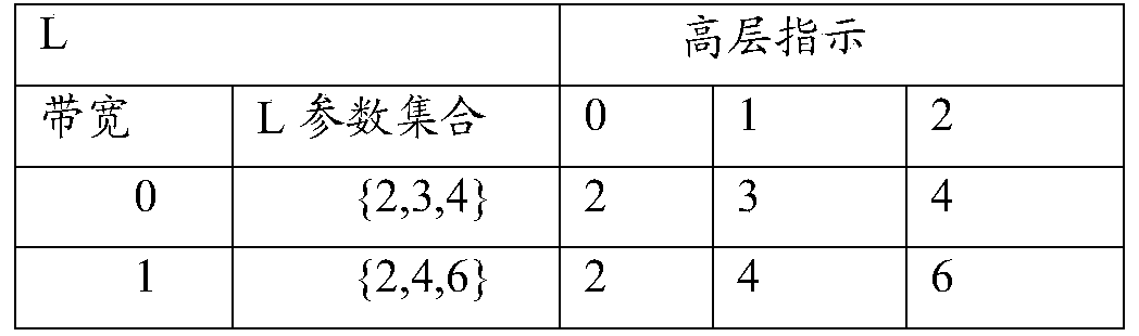
And respectively configuring the reporting parameters of the at least one terminal device to different terminal devices in an explicit or implicit mode. When the non-displayed indication is different from the L value, the indication range (0, 1,2) may be configured by a high-level indication, as shown in the following table, that is, when the implicit indication is performed, any one of 0,1,2 may be included, and then the terminal device determines the specific L value indicated by the network device according to the numerical value of the implicit indication.

Examples 1-2, p-configurations of different layers may come from different parameter sets, e.g., the following table

When the terminal device reports the layer 1 and the layer 2, the network device can only select one value from the parameter set {3/4,1/2} to configure the terminal; for the UE to report the layer 3 and the layer 4, the network can only select one value from the parameter set {1/2,1/4} to configure the terminal; when the non-displayed indications differ in p-value, it can be configured by a high level indication (indicating range 0,1,2), as shown in the following table:

scene 2, determining the number of reported layers reported by the terminal; the terminal calculates the RI.
It is to be understood that scenarios 1,2 may be used in combination.
For different reporting layer numbers and/or a high layer indication, there are different reporting parameters.
According to the condition of the indication information, calculating the data of each layer
For different reporting layers, the same or different L can be arranged according to the configuration
For different reporting layer numbers, the same or different M may exist, and different M may be determined by N3 and different p and or R contained in the indication information; for example:


Wherein, i corresponds to different reporting layer numbers.
For different layers, there may be the same or different K0, depending on the configuration;

wherein, i corresponds to different reporting layer numbers.
For different reporting layers, the same or different amplitude and phase quantization precisions can be provided according to the configuration.
The same foregoing calculations may be combined to ultimately obtain at least one of them.
The terminal encodes and reports the W of each layer according to a certain sequence; the network side obtains the channel information of each layer according to a predetermined sequence.
Examples 2-1,
The L configurations for different reporting layer numbers may come from different parameter sets, such as the following table:
| reporting layer number | L |
| 0 | {2,3,4} |
| 1 | {2,3,4} |
| 2 | {2,4,6} |
| 3 | {2,4,6} |
When the reported layer number of the UE is 1 and 2, the network can only select one value from the parameter set {2,3,4} to configure the terminal; when the number of reported layers reported by the UE is 3 and 4, the network can only select one value from the parameter set {2,4,6} to configure the terminal.
It should be noted that the indication information may explicitly or implicitly indicate the terminal device, for example, when different L values are provided, the indication information may be configured by a higher layer indication (indicating range 0,1,2), as shown in the following table:

example 2-2, the aforementioned scenarios 1,2 may be used in combination, examples are as follows: that is, the L configurations of different reporting layers and different layers can be from different parameter sets, for example, the following table
| Reporting layer number | | L | |
| 1 | 0 | {2,3,4} | |
| 2 | 0 | {2,3,4} | |
| 2 | 1 | {2,3,6} | |
| 3 | 0 | {2,4,6} | |
| 3 | 1 | {2,3,4} | |
| 3 | 2 | {2,3,4} | |
| 4 | 0 | {2,4,6} | |
| 4 | 1 | {2,4,6} | |
| 4 | 2 | {2,3,4} | |
| 4 | 3 | {2,3,4} |
Examples 2-3, the M configurations of different reporting layer numbers may be from different parameter sets, for example, the following table (M is determined by higher layer configuration p), in this embodiment, performance priority is considered, that is, the higher the layer number is, the more feedback is; the overhead can be set to be preferential, that is, the higher the layer number is, the smaller the value range of p is; as shown in the following table:
| reporting layer number | P |
| 0 | {1/2,1/4} |
| 1 | {1/2,1/4} |
| 2 | {3/4,1/2} |
| 3 | {3/4,1/2} |
When the reported layer number of the UE is 1 and 2, the network can only select one value from the parameter set {1/2,1/4} to configure the terminal; when the reported layer number of the UE is 3 and 4, the network can only select one value from the parameter set {3/4,1/2} to configure the terminal; when the non-displayed indications are different p-values, it can be configured by a high level indication (indicating range 0,1,2), such as shown in the following table:

further alternatively, the different number of reporting layers and the p-configurations of the different layers may be from different parameter sets, for example, as shown in the following table
| Reporting layer number | | p | |
| 1 | 0 | {3/4,1/2} | |
| 2 | 0 | {3/4,1/2} | |
| 2 | 1 | {3/4,1/2} | |
| 3 | 0 | {3/4,1/2} | |
| 3 | 1 | {1/2,1/4} | |
| 3 | 2 | {1/2,1/4} | |
| 4 | 0 | {3/4,1/2} | |
| 4 | 1 | {3/4,1/2} | |
| 4 | 2 | {1/2,1/4} | |
| 4 | 3 | {1/2,1/4} |
Example 2-4, the high layer configuration beta value of the control parameter K0 may also be determined for different reporting layer numbers and/or reporting layers and/or terminal capabilities, see the following table, and take the terminal capability as an illustration, and the processing of combining other parameters is not described herein again.
| Terminal capabilities | Beta |
| 0 | {3/4,1/2} |
| 1 | {1/4,1/8} |
And 3, determining the CSI measurement bandwidth reported by the terminal.
Firstly, terminal equipment reports the CSI measurement bandwidth of the terminal equipment to network equipment, and the network equipment determines corresponding indication information according to the capacity of the terminal equipment; and the terminal equipment determines the reporting parameters according to the indication information.
Calculating for each layer
Different reported CSI measurement bandwidths can have the same or different L according to configuration
Different reported CSI measurement bandwidths can have the same or different M according to the configuration, and the different M is determined by N3 and different p and/or R; for example


Wherein i corresponds to different reported CSI measurement bandwidths, i is 0 when N3/R is less than T; when N3/R > is T, i is 1; (or when N3< T, i ═ 0; when N3> -T, i ═ 1).
Different reported CSI measurement bandwidths can have the same or different K0 according to configuration

Wherein i corresponds to different reported CSI measurement bandwidths, i is 0 when N3/R is less than T; when N3/R > is T, i is 1; (or when N3< T, i ═ 0; when N3> -T, i ═ 1).
Different reported CSI measurement bandwidths can have the same or different amplitude and phase quantization precisions according to configuration
The terminal equipment encodes and reports the W of each layer according to a certain sequence; the network side obtains the channel information of each layer according to a predetermined sequence.
Example 3-1, L configurations of different bandwidths may be from different parameter sets, e.g., the following Table
| Bandwidth of | L |
| 0 | {2,3,4} |
| 1 | {2,4,6} |
When the reporting bandwidth of the UE is less than a threshold (e.g., N3/R < ═ T, e.g.t is 13PRB), the network can only select one value from the parameter set {2,3,4} to configure the terminal;
when the reported bandwidth of the UE is greater than the threshold (for example, N3/R > T), the network can only select one value from the parameter set {2,4,6} to configure the terminal;
when non-displayed indications are different values of L, it can be configured by a high level indication (indicating range 0,1,2), see the following table:
similarly, the parameters L and/or M (p) and/or K0(beta) can be distinguished by bandwidth, but are not exhaustive here.
Scenario 4, determined by terminal capabilities
And determining the reporting parameters according to the capability indication of the terminal.
Calculating for each layer
The capability indications of different terminals can have the same or different L according to the configuration;
the capability indications for different terminals may be the same or different M according to the configuration, the different M being determined by N3 and different p and or R; for example:


Where i corresponds to the capability indication of the different terminal.
For different layers, there may be the same or different K0 depending on the configuration

Where i corresponds to the capability indication of the different terminal.
The capability indication of different terminals can have the same or different amplitude and phase quantization precision according to the configuration;
the foregoing centralized computations may be combined arbitrarily.
The terminal encodes and reports the W of each layer according to a certain sequence; the network side obtains the channel information of each layer according to a predetermined sequence.
Example 4-1, parameter L is determined by different terminal capabilities, e.g. the correspondence of terminal capabilities to corresponding parameter sets:
| terminal capabilities | L |
| 0 | {2,3,4} |
| 1 | {2,4,6} |
When the terminal accesses the network, the terminal reports the capability of the UE, and after the network receives the terminal information, the network can only select any parameter value from the corresponding parameter set to configure the parameter value to the terminal.
Examples 4-2,
The parameter p is determined by different terminal capabilities, e.g. the correspondence of the terminal capabilities to the corresponding parameter sets, see the following table:
| terminal capabilities | p |
| 0 | {3/4,1/2} |
| 1 | {1/2,1/4} |
When the terminal accesses the network, the capability of one UE is reported, and after the network receives the terminal information, the network can only select any one parameter value from the corresponding parameter set to configure the parameter value to the terminal.
Therefore, by adopting the scheme, the corresponding parameters can be configured for the terminal equipment according to the relevant information of the terminal equipment, and then the terminal equipment determines at least one layer of channel information and sends the channel information to the network equipment; the related information may include information of at least one layer. Therefore, the codebook can be expanded to a high layer based on the condition of the terminal equipment, and different indication information can be provided for different terminal equipment, so that the accuracy of the channel information determined by different terminal equipment according to the self condition is improved. And because the relevant information of different terminal devices is combined, the terminal devices without corresponding capability can be prevented from reporting parameters at a higher level, thereby improving the robustness and the feasibility of the system.
Example II,
An embodiment of the present invention provides a codebook information processing method, which is applied to a terminal device, and as shown in fig. 3, the codebook information processing method includes:
step 31: receiving a reporting parameter configured by the network equipment; the reporting parameters are that different terminal devices can correspond to different reporting parameters, and the terminal devices have different reporting parameters under different conditions; the reporting parameter comprises at least one of the following parameters: the number of space basis vectors, the number of frequency basis vectors, the maximum number of non-0 elements.
The method may further comprise:
and sending the terminal capability information to the network equipment.
The reporting parameter includes at least one of the following parameters:
the number of spatial basis vectors corresponding to each layer;
the number of space basis vectors corresponding to the number of reported layers;
the number of the space basis vectors corresponding to the reported CSI measurement bandwidth of the terminal equipment;
the number of spatial basis vectors corresponding to the capabilities of the terminal device;
at least one parameter for determining a number of frequency domain basis vectors corresponding to each layer;
at least one parameter for determining the number of frequency domain basis vectors corresponding to the number of reporting layers;
at least one parameter for determining a maximum number of non-0 elements corresponding to each layer;
and at least one parameter used for determining the maximum number of the non-0 elements corresponding to the number of reporting layers.
Specifically, the scheme provided in this embodiment can define multiple sets of relevant parameters of the terminal device, so as to send indication information to the terminal device based on at least one of different capabilities, different reporting layers, different layers, and different reporting bandwidths, where the indication information includes at least one type of information, so that the terminal device reports channel information according to the parameters corresponding to the indication information.
Reporting parameters, further comprising at least one of:
quantization precision of amplitude and/or quantization precision of phase corresponding to each layer;
the quantization precision of the amplitude and/or the quantization precision of the phase corresponding to the number of reported layers;
the quantization precision of the amplitude and/or the quantization precision of the phase corresponding to the CSI measurement bandwidth of the terminal device;
quantization accuracy of amplitude and/or quantization accuracy of phase corresponding to the capability of the terminal device.
That is, the reporting parameter may specifically include at least one of the following:
the number L of the space basis vectors basic;
the number M of frequency basis;
the number of the maximum reporting elements K0;
the quantization precision of the amplitude;
quantization precision of the phase;
adopting the number of quantization with different amplitudes;
number of phase precision quantizations.
The reporting parameters may be one or more reporting parameters combined.
It should be understood that at least one parameter included in the foregoing indication information may be determined by the network device according to the layer number and/or the reporting layer number of the terminal device. When the number of reporting layers is different, the terminal reports by adopting different parameters; the method has two meanings: different parameter sets are adopted for different layers (layers) in a terminal device; different terminal devices have different reporting layer numbers (RIs), and different terminal devices can adopt different parameter sets.
Determined by the bandwidth of the terminal device. For example, the determination may be performed according to a threshold, for example, when the number of sub-bands reported by the terminal device CSI is smaller than the bandwidth threshold, a first type of parameter is used, and otherwise, a second type of parameter is used;
determined by the terminal capabilities. The terminal reports a capability indication to the network, and the network configures the terminal to adopt corresponding parameters through the indication information. It should be noted that the foregoing parameter may be one parameter, and may be a parameter group consisting of a plurality of parameters.
The method further comprises the following steps: and coding and reporting the channel information of each layer based on the reporting parameters.
The following describes the scheme in detail in various scenarios:
According to different layers and/or a high layer indication, determining the reporting parameters.
Calculating for each layer At least one layer of the terminal device may adopt the same configuration, for example, the current rank-2 design, but may also adopt a different configuration.
Specifically, for different layers, the same or different L may be configured according to the indication information of the network device;
for different layers, the same or different M can be obtained according to at least one parameter in the indication information; wherein at least one parameter may be N3, different p, and/or different R;
specific ways to calculate the M value of each layer are, for example:


Where i denotes the different layers of the terminal device. For example, the terminal device has two layers, i is 1 and 2 respectively, i.e. M values of the first layer and the second layer are calculated respectively.
For different layers, there may be the same or different K0 according to the configuration, and the calculation method may be:

Still further, for different layers, the quantization precision of amplitude and phase can be the same or different according to the indication information
Determining at least one layer of coded channel information for codebook calculation based on the at least one reporting parameter; and sending the coded channel information of the at least one layer for performing codebook calculation to network equipment.
That is, the terminal device encodes and reports the W of each layer according to a preset sequence; the network side obtains the channel information of each layer according to a predetermined sequence. The preset order may be from a high layer to a low layer or from a low layer to a high layer.
For the In the reporting, the network device may configure an L value, that is, the number of the space basis vectors; for Rel-15, L is a constant of RRC configuration, and the value range is {2,3,4 }; for the Rel-16MIMO enhancement in question, the values of L are {2, 4}, {3, 6} pending.
An M value (related to the bandwidth of the reported frequency domain) is adopted, namely the quantity of the reported frequency basis vectors is configured by a higher layer, wherein N3 is the quantity of the candidate frequency basis vectors, and R is 1 or 2, which is a parameter configured by the higher layer;
using a value of K0, constraining Reporting the maximum number of elements, which also belongs to high-level configuration;
determined by a bitmap and/or an indication Number of non-0 elements in (A) and/or (B)
 The position of (1);
determined by one or more sets of (amplitude, phase) parameters The quantization precision in (1), for example, the amplitude is 3/4bit, and the phase is quantized with 3/4 bit;
for a part of elements with larger amplitude (for example, the first 50%), 4 bits are adopted for amplitude, and 3 bits are adopted for phase quantization; the smaller part adopts 2-bit amplitude, and 2-bit phase quantization;
for the 0 th frequency basis, (amplitude, phase) (4,4) bit quantization is used, and for the other frequency basis, (amplitude, phase) (3,3) bit quantization is used;
physical meaning of the parameters:
l indicates the number of columns of W1, in fact, the number of columns of W1 is 2L, two polarization directions correspond to the same SD basis, and the codebook feeds back channel information of the L SD bases;
m indicates The M columns are selected from a total of N3 FD bases, and the codebook feeds back channel information of the M FD bases;
k0 denotes The maximum number of non-0 elements of (a),
 the (i, j) th element of (a) describes the weighting coefficients of the ith SD basis and the jth FD basis. (K0 is the maximum number of non-zero elements, which can be smaller than K0 reported in practice).
Scene 2, determining the number of reported layers reported by the terminal; the terminal calculates the RI.
It is to be understood that scenarios 1,2 may be used in combination.
For different reporting layer numbers and/or a high layer indication, there are different reporting parameters.
According to the condition of the indication information, calculating the data of each layer
For different reporting layers, the same or different L can be arranged according to the configuration
For different reporting layer numbers, the same or different M may exist, and different M may be determined by N3 and different p and or R contained in the indication information; for example:

Wherein, i corresponds to different reporting layer numbers.
For different layers, there may be the same or different K0 depending on the configuration

Wherein, i corresponds to different reporting layer numbers.
For different reporting layers, the same or different amplitude and phase quantization precisions can be provided according to the configuration.
The same foregoing calculations may be combined to ultimately obtain at least one of them.
The terminal encodes and reports the W of each layer according to a certain sequence; the network side obtains the channel information of each layer according to a predetermined sequence.
And 3, determining the CSI measurement bandwidth reported by the terminal.
Firstly, terminal equipment reports the CSI measurement bandwidth of the terminal equipment to network equipment, and the network equipment determines corresponding indication information according to the capacity of the terminal equipment; and the terminal equipment determines the reporting parameters according to the indication information.
Calculating for each layer
Different reported CSI measurement bandwidths can have the same or different L according to configuration
Different reported CSI measurement bandwidths can have the same or different M according to the configuration, and the different M is determined by N3 and different p and/or R; for example

Wherein i corresponds to different reported CSI measurement bandwidths, i is 0 when N3/R is less than T; when N3/R > is T, i is 1; (or when N3< T, i ═ 0; when N3> -T, i ═ 1).
Different reported CSI measurement bandwidths can have the same or different K0 according to configuration

Wherein i corresponds to different reported CSI measurement bandwidths, i is 0 when N3/R is less than T; when N3/R > is T, i is 1; (or when N3< T, i ═ 0; when N3> -T, i ═ 1).
Different reported CSI measurement bandwidths can have the same or different amplitude and phase quantization precisions according to configuration
The terminal equipment encodes and reports the W of each layer according to a certain sequence; the network side obtains the channel information of each layer according to a predetermined sequence.
Scenario 4, determined by terminal capabilities
And determining the reporting parameters according to the capability indication of the terminal.
Calculating for each layer
The capability indications of different terminals can have the same or different L according to the configuration;
the capability indications for different terminals may be the same or different M according to the configuration, the different M being determined by N3 and different p and or R; for example:


Where i corresponds to the capability indication of the different terminal.
For different layers, there may be the same or different K0 depending on the configuration

Where i corresponds to the capability indication of the different terminal.
The capability indication of different terminals can have the same or different amplitude and phase quantization precision according to the configuration;
the foregoing centralized computations may be combined arbitrarily.
The terminal encodes and reports the W of each layer according to a certain sequence; the network side obtains the channel information of each layer according to a predetermined sequence.
Therefore, by adopting the scheme, the corresponding parameters can be configured for the terminal equipment according to the relevant information of the terminal equipment, and then the terminal equipment determines at least one layer of channel information and sends the channel information to the network equipment; the related information may include information of at least one layer. Therefore, the codebook can be expanded to a high layer based on the condition of the terminal equipment, and different indication information can be provided for different terminal equipment, so that the accuracy of the channel information determined by different terminal equipment according to the self condition is improved. And because the relevant information of different terminal devices is combined, the terminal devices without corresponding capability can be prevented from reporting parameters at a higher level, thereby improving the robustness and the feasibility of the system.
Example III,
An embodiment of the present invention provides a network device, as shown in fig. 4, including:
a first communication unit 41, configured to determine a corresponding reporting parameter for at least one terminal device; reporting parameters corresponding to different terminal devices are different; the same terminal equipment corresponds to different reporting parameters under different conditions; the reporting parameter comprises at least one of the following parameters: the number of spatial basis vectors;
the first processing unit 42 is configured to configure the reporting parameters of the at least one terminal device to different terminal devices, respectively.
It should be noted that, in this embodiment, reporting parameters are determined for terminal devices, where different terminal devices may have different capabilities, and thus different terminal devices may correspond to different reporting parameters; furthermore, the same terminal device may have the same reporting parameters under the same conditions, and may have different reporting parameters under different conditions. The following specifically explains the process.
The first communication unit 41 receives different terminal capability information transmitted from at least one terminal device.
Correspondingly, the first processing unit 42 determines different reporting parameters for different terminal devices based on the different terminal capability information.
The terminal capability information may be determined by using different parameters, for example, different delays, different QoS, processing capability of the terminal device, processing resources, and the like may be used to determine different terminal capability information.
The network device may classify the capability information of the terminal device in advance, for example, after classifying various types of terminal devices, different reporting parameters are determined for different types of terminal devices.
The conditions include: reporting the layer number and/or CSI measurement bandwidth.
That is, different reporting parameters may be allocated to the same terminal device under the condition of different numbers of reporting layers and/or different CSI measurement bandwidths. The same terminal device may have different reporting layer numbers under different conditions, and may also have different CSI measurement bandwidths according to actual conditions.
Further, the first processing unit 42 determines different reporting parameters for the terminal device based on the condition that the terminal device has different reporting layer numbers and/or different CSI measurement bandwidths. Different reporting layer numbers can correspond to different reporting parameters, and the reporting parameters corresponding to different layers can be determined based on the reporting layer numbers. In addition, a bandwidth threshold value can be provided, and different reporting parameters are determined by comparing the CSI measurement bandwidth with the bandwidth threshold value.
The reporting parameter includes at least one of the following parameters:
the number of spatial basis vectors corresponding to each layer;
the number of space basis vectors corresponding to the number of reported layers;
the number of the space basis vectors corresponding to the reported CSI measurement bandwidth of the terminal equipment;
the number of spatial basis vectors corresponding to the capabilities of the terminal device;
at least one parameter for determining a number of frequency domain basis vectors corresponding to each layer;
at least one parameter for determining the number of frequency domain basis vectors corresponding to the number of reporting layers;
at least one parameter for determining a maximum number of non-0 elements corresponding to each layer;
and at least one parameter used for determining the maximum number of the non-0 elements corresponding to the number of reporting layers.
Reporting parameters, further comprising at least one of:
quantization precision of amplitude and/or quantization precision of phase corresponding to each layer;
the quantization precision of the amplitude and/or the quantization precision of the phase corresponding to the number of reported layers;
the quantization precision of the amplitude and/or the quantization precision of the phase corresponding to the CSI measurement bandwidth of the terminal device;
quantization accuracy of amplitude and/or quantization accuracy of phase corresponding to the capability of the terminal device.
Specifically, the scheme provided in this embodiment can define multiple sets of relevant parameters of the terminal device, so as to send indication information to the terminal device based on at least one of different capabilities, different reporting layers, different layers, and different reporting bandwidths, where the indication information includes at least one type of information, so that the terminal device reports channel information according to the parameters corresponding to the indication information.
The reporting parameter comprises at least one of the following parameters:
the number L of the space basis vectors basic;
the number M of frequency basis;
the number of the maximum reporting elements K0;
the quantization precision of the amplitude;
quantization precision of the phase;
adopting the number of quantization with different amplitudes;
number of phase precision quantizations.
The reporting parameters may be one or more reporting parameters combined.
The following describes the scheme in detail in various scenarios:
According to different layers and/or a high layer indication, determining the reporting parameters.
Calculating for each layer At least one layer of the same terminal device may adopt the same configuration, for example, the current rank-2 design, but may also adopt a different configuration.
Specifically, for different layers, the same or different L may be configured according to the indication information of the network device;
for different layers, the same or different M can be obtained according to at least one parameter in the indication information; wherein at least one parameter may be N3, different p, and/or different R;
specific ways to calculate the M value of each layer are, for example:


Where i denotes the different layers of the terminal device. For example, the terminal device has two layers, i is 1 and 2 respectively, i.e. M values of the first layer and the second layer are calculated respectively.
For different layers, there may be the same or different K0 according to the configuration, and the calculation method may be:

Still further, for different layers, the quantization precision of amplitude and phase can be the same or different according to the indication information
Determining at least one layer of coded channel information for codebook calculation based on the at least one reporting parameter; and sending the coded channel information of the at least one layer for performing codebook calculation to network equipment.
That is, the terminal device encodes and reports the W of each layer according to a preset sequence; the network side obtains the channel information of each layer according to a predetermined sequence. The preset order may be from a high layer to a low layer or from a low layer to a high layer.
For the In the reporting, the network device may configure an L value, that is, the number of the space basis vectors; for Rel-15, L is a constant of RRC configuration, and the value range is {2,3,4 }; for the Rel-16MIMO enhancement in question, the values of L are {2, 4}, {3, 6} pending.
An M value (related to the bandwidth of the reported frequency domain) is adopted, namely the quantity of the reported frequency basis vectors is configured by a higher layer, wherein N3 is the quantity of the candidate frequency basis vectors, and R is 1 or 2, which is a parameter configured by the higher layer;
using a value of K0, constraining Reporting the maximum number of elements, which also belongs to high-level configuration;
determined by a bitmap and/or an indication Number of non-0 elements in (A) and/or (B)
 The position of (1);
determined by one or more sets of (amplitude, phase) parameters The quantization precision in (1), for example, the amplitude is 3/4bit, and the phase is quantized with 3/4 bit;
for a part of elements with larger amplitude (for example, the first 50%), 4 bits are adopted for amplitude, and 3 bits are adopted for phase quantization; the smaller part adopts 2-bit amplitude, and 2-bit phase quantization;
for the 0 th frequency basis, (amplitude, phase) (4,4) bit quantization is used, and for the other frequency basis, (amplitude, phase) (3,3) bit quantization is used;
physical meaning of the parameters:
l indicates the number of columns of W1, in fact, the number of columns of W1 is 2L, two polarization directions correspond to the same SD basis, and the codebook feeds back channel information of the L SD bases;
m indicates The M columns are selected from a total of N3 FD bases, and the codebook feeds back channel information of the M FD bases;
k0 denotes The maximum number of non-0 elements of (a),
 the (i, j) th element of (a) describes the weighting coefficients of the ith SD basis and the jth FD basis. (K0 is the maximum number of non-zero elements, which can be smaller than K0 reported in practice).
Scene 2, determining the number of reported layers reported by the terminal; the terminal calculates the RI.
It is to be understood that scenarios 1,2 may be used in combination.
For different reporting layer numbers and/or a high layer indication, there are different reporting parameters.
According to the condition of the indication information, calculating the data of each layer
For different reporting layers, the same or different L can be arranged according to the configuration
For different reporting layer numbers, the same or different M may exist, and different M may be determined by N3 and different p and or R contained in the indication information; for example:

Wherein, i corresponds to different reporting layer numbers.
For different layers, there may be the same or different K0 depending on the configuration

Wherein, i corresponds to different reporting layer numbers.
For different reporting layers, the same or different amplitude and phase quantization precisions can be provided according to the configuration.
The same foregoing calculations may be combined to ultimately obtain at least one of them.
The terminal encodes and reports the W of each layer according to a certain sequence; the network side obtains the channel information of each layer according to a predetermined sequence.
And 3, determining the CSI measurement bandwidth reported by the terminal.
Firstly, terminal equipment reports the CSI measurement bandwidth of the terminal equipment to network equipment, and the network equipment determines corresponding indication information according to the capacity of the terminal equipment; and the terminal equipment determines the reporting parameters according to the indication information.
Calculating for each layer
Different reported CSI measurement bandwidths can have the same or different L according to configuration
Different reported CSI measurement bandwidths can have the same or different M according to the configuration, and the different M is determined by N3 and different p and/or R; for example


Wherein i corresponds to different reported CSI measurement bandwidths, i is 0 when N3/R is less than T; when N3/R > is T, i is 1; (or when N3< T, i ═ 0; when N3> -T, i ═ 1).
Different reported CSI measurement bandwidths can have the same or different K0 according to configuration

Wherein i corresponds to different reported CSI measurement bandwidths, i is 0 when N3/R is less than T; when N3/R > is T, i is 1; (or when N3< T, i ═ 0; when N3> -T, i ═ 1).
Different reported CSI measurement bandwidths can have the same or different amplitude and phase quantization precisions according to configuration
The terminal equipment encodes and reports the W of each layer according to a certain sequence; the network side obtains the channel information of each layer according to a predetermined sequence.
Scenario 4, determined by terminal capabilities
And determining the reporting parameters according to the capability indication of the terminal.
Calculating for each layer
The capability indications of different terminals can have the same or different L according to the configuration;
the capability indications for different terminals may be the same or different M according to the configuration, the different M being determined by N3 and different p and or R; for example:


Where i corresponds to the capability indication of the different terminal.
For different layers, there may be the same or different K0 depending on the configuration

Where i corresponds to the capability indication of the different terminal.
The capability indication of different terminals can have the same or different amplitude and phase quantization precision according to the configuration;
the foregoing centralized computations may be combined arbitrarily.
The terminal encodes and reports the W of each layer according to a certain sequence; the network side obtains the channel information of each layer according to a predetermined sequence.
Therefore, by adopting the scheme, the corresponding parameters can be configured for the terminal equipment according to the relevant information of the terminal equipment, and then the terminal equipment determines at least one layer of channel information and sends the channel information to the network equipment; the related information may include information of at least one layer. Therefore, the codebook can be expanded to a high layer based on the condition of the terminal equipment, and different indication information can be provided for different terminal equipment, so that the accuracy of the channel information determined by different terminal equipment according to the self condition is improved. And because the relevant information of different terminal devices is combined, the terminal devices without corresponding capability can be prevented from reporting parameters at a higher level, thereby improving the robustness and the feasibility of the system.
Example four,
An embodiment of the present invention provides a terminal device, as shown in fig. 5, including:
the second communication unit 51 receives the reporting parameters configured by the network device; the reporting parameters are that different terminal devices can correspond to different reporting parameters, and the terminal devices have different reporting parameters under different conditions; the reporting parameter comprises at least one of the following parameters: the number of space basis vectors, the number of frequency basis vectors, the maximum number of non-0 elements.
The second communication unit 51 transmits the terminal capability information to the network device.
The reporting parameter includes at least one of the following parameters:
the number of spatial basis vectors corresponding to each layer;
the number of space basis vectors corresponding to the number of reported layers;
the number of the space basis vectors corresponding to the reported CSI measurement bandwidth of the terminal equipment;
the number of spatial basis vectors corresponding to the capabilities of the terminal device;
at least one parameter for determining a number of frequency domain basis vectors corresponding to each layer;
at least one parameter for determining the number of frequency domain basis vectors corresponding to the number of reporting layers;
at least one parameter for determining a maximum number of non-0 elements corresponding to each layer;
and at least one parameter used for determining the maximum number of the non-0 elements corresponding to the number of reporting layers.
Specifically, the scheme provided in this embodiment can define multiple sets of relevant parameters of the terminal device, so as to send indication information to the terminal device based on at least one of different capabilities, different reporting layers, different layers, and different reporting bandwidths, where the indication information includes at least one type of information, so that the terminal device reports channel information according to the parameters corresponding to the indication information.
Reporting parameters, further comprising at least one of:
quantization precision of amplitude and/or quantization precision of phase corresponding to each layer;
the quantization precision of the amplitude and/or the quantization precision of the phase corresponding to the number of reported layers;
the quantization precision of the amplitude and/or the quantization precision of the phase corresponding to the CSI measurement bandwidth of the terminal device;
quantization accuracy of amplitude and/or quantization accuracy of phase corresponding to the capability of the terminal device.
That is, the reporting parameter may specifically include at least one of the following:
the number L of the space basis vectors basic;
the number M of frequency basis;
the number of the maximum reporting elements K0;
the quantization precision of the amplitude;
quantization precision of the phase;
adopting the number of quantization with different amplitudes;
number of phase precision quantizations.
The reporting parameters may be one or more reporting parameters combined.
It should be understood that at least one parameter included in the foregoing indication information may be determined by the network device according to the layer number and/or the reporting layer number of the terminal device. When the number of reporting layers is different, the terminal reports by adopting different parameters; the method has two meanings: different parameter sets are adopted for different layers (layers) in a terminal device; different terminal devices have different reporting layer numbers (RIs), and different terminal devices can adopt different parameter sets.
Determined by the bandwidth of the terminal device. For example, the determination may be performed according to a threshold, for example, when the number of sub-bands reported by the terminal device CSI is smaller than the bandwidth threshold, a first type of parameter is used, and otherwise, a second type of parameter is used;
determined by the terminal capabilities. The terminal reports a capability indication to the network, and the network configures the terminal to adopt corresponding parameters through the indication information. It should be noted that the foregoing parameter may be one parameter, and may be a parameter group consisting of a plurality of parameters.
The second communication unit 51 performs coding reporting on the channel information of each layer based on the reporting parameters.
The following describes the scheme in detail in various scenarios:
According to different layers and/or a high layer indication, determining the reporting parameters.
Calculating for each layer Wherein at least one layer of the terminal equipment can adopt the same configuration, such as current rank 2, although different configurations may be used.
Specifically, for different layers, the same or different L may be configured according to the indication information of the network device;
for different layers, the same or different M can be obtained according to at least one parameter in the indication information; wherein at least one parameter may be N3, different p, and/or different R;
specific ways to calculate the M value of each layer are, for example:


Where i denotes the different layers of the terminal device. For example, the terminal device has two layers, i is 1 and 2 respectively, i.e. M values of the first layer and the second layer are calculated respectively.
For different layers, there may be the same or different K0 according to the configuration, and the calculation method may be:

Still further, for different layers, the quantization precision of amplitude and phase can be the same or different according to the indication information
Determining at least one layer of coded channel information for codebook calculation based on the at least one reporting parameter; and sending the coded channel information of the at least one layer for performing codebook calculation to network equipment.
That is, the terminal device encodes and reports the W of each layer according to a preset sequence; the network side obtains the channel information of each layer according to a predetermined sequence. The preset order may be from a high layer to a low layer or from a low layer to a high layer.
For the In the reporting, the network device may configure an L value, that is, the number of the space basis vectors; for Rel-15, L is a constant of RRC configuration, and the value range is {2,3,4 }; for the Rel-16MIMO enhancement in question, the values of L are {2, 4}, {3, 6} pending.
An M value (related to the bandwidth of the reported frequency domain) is adopted, namely the quantity of the reported frequency basis vectors is configured by a higher layer, wherein N3 is the quantity of the candidate frequency basis vectors, and R is 1 or 2, which is a parameter configured by the higher layer;
using a value of K0, constraining Reporting the maximum number of elements, which also belongs to high-level configuration;
determined by a bitmap and/or an indication Number of non-0 elements in (A) and/or (B)
 The position of (1);
determined by one or more sets of (amplitude, phase) parameters The quantization precision in (1), for example, the amplitude is 3/4bit, and the phase is quantized with 3/4 bit;
for a part of elements with larger amplitude (for example, the first 50%), 4 bits are adopted for amplitude, and 3 bits are adopted for phase quantization; the smaller part adopts 2-bit amplitude, and 2-bit phase quantization;
for the 0 th frequency basis, (amplitude, phase) (4,4) bit quantization is used, and for the other frequency basis, (amplitude, phase) (3,3) bit quantization is used;
physical meaning of the parameters:
l indicates the number of columns of W1, in fact, the number of columns of W1 is 2L, two polarization directions correspond to the same SD basis, and the codebook feeds back channel information of the L SD bases;
m indicates The M columns are selected from a total of N3 FD bases, and the codebook feeds back channel information of the M FD bases;
k0 denotes The maximum number of non-0 elements of (a),
 the (i, j) th element of (a) describes the weighting coefficients of the ith SD basis and the jth FD basis. (K0 is the maximum number of non-zero elements, which can be smaller than K0 reported in practice).
Scene 2, determining the number of reported layers reported by the terminal; the terminal calculates the RI.
It is to be understood that scenarios 1,2 may be used in combination.
For different reporting layer numbers and/or a high layer indication, there are different reporting parameters.
According to the condition of the indication information, calculating the data of each layer
For different reporting layers, the same or different L can be arranged according to the configuration
For different reporting layer numbers, the same or different M may exist, and different M may be determined by N3 and different p and or R contained in the indication information; for example:


Wherein, i corresponds to different reporting layer numbers.
For different layers, there may be the same or different K0 depending on the configuration

Wherein, i corresponds to different reporting layer numbers.
For different reporting layers, the same or different amplitude and phase quantization precisions can be provided according to the configuration.
The same foregoing calculations may be combined to ultimately obtain at least one of them.
The terminal encodes and reports the W of each layer according to a certain sequence; the network side obtains the channel information of each layer according to a predetermined sequence.
And 3, determining the CSI measurement bandwidth reported by the terminal.
Firstly, terminal equipment reports the CSI measurement bandwidth of the terminal equipment to network equipment, and the network equipment determines corresponding indication information according to the capacity of the terminal equipment; and the terminal equipment determines the reporting parameters according to the indication information.
Calculating for each layer
Different reported CSI measurement bandwidths can have the same or different L according to configuration
Different reported CSI measurement bandwidths can have the same or different M according to the configuration, and the different M is determined by N3 and different p and/or R; for example


Wherein i corresponds to different reported CSI measurement bandwidths, i is 0 when N3/R is less than T; when N3/R > is T, i is 1; (or when N3< T, i ═ 0; when N3> -T, i ═ 1).
Different reported CSI measurement bandwidths can have the same or different K0 according to configuration

Wherein i corresponds to different reported CSI measurement bandwidths, i is 0 when N3/R is less than T; when N3/R > is T, i is 1; (or when N3< T, i ═ 0; when N3> -T, i ═ 1).
Different reported CSI measurement bandwidths can have the same or different amplitude and phase quantization precisions according to configuration
The terminal equipment encodes and reports the W of each layer according to a certain sequence; the network side obtains the channel information of each layer according to a predetermined sequence.
Scenario 4, determined by terminal capabilities
And determining the reporting parameters according to the capability indication of the terminal.
Calculating for each layer
The capability indications of different terminals can have the same or different L according to the configuration;
the capability indications for different terminals may be the same or different M according to the configuration, the different M being determined by N3 and different p and or R; for example:


Where i corresponds to the capability indication of the different terminal.
For different layers, there may be the same or different K0 depending on the configuration

Where i corresponds to the capability indication of the different terminal.
The capability indication of different terminals can have the same or different amplitude and phase quantization precision according to the configuration;
the foregoing centralized computations may be combined arbitrarily.
The terminal encodes and reports the W of each layer according to a certain sequence; the network side obtains the channel information of each layer according to a predetermined sequence.
Therefore, by adopting the scheme, the corresponding parameters can be configured for the terminal equipment according to the relevant information of the terminal equipment, and then the terminal equipment determines at least one layer of channel information and sends the channel information to the network equipment; the related information may include information of at least one layer. Therefore, the codebook can be expanded to a high layer based on the condition of the terminal equipment, and different indication information can be provided for different terminal equipment, so that the accuracy of the channel information determined by different terminal equipment according to the self condition is improved. And because the relevant information of different terminal devices is combined, the terminal devices without corresponding capability can be prevented from reporting parameters at a higher level, thereby improving the robustness and the feasibility of the system.
Fig. 6 is a schematic structural diagram of a communication device 600 according to an embodiment of the present application, where the communication device may be the terminal device or the network device described above in this embodiment. The communication device 600 shown in fig. 6 includes a processor 610, and the processor 610 can call and run a computer program from a memory to implement the method in the embodiment of the present application.
Optionally, as shown in fig. 6, the communication device 600 may further include a memory 620. From the memory 620, the processor 610 may call and run a computer program to implement the method in the embodiment of the present application.
The memory 620 may be a separate device from the processor 610, or may be integrated into the processor 610.
Optionally, as shown in fig. 6, the communication device 600 may further include a transceiver 630, and the processor 610 may control the transceiver 630 to communicate with other devices, and specifically, may transmit information or data to the other devices or receive information or data transmitted by the other devices.
The transceiver 630 may include a transmitter and a receiver, among others. The transceiver 630 may further include one or more antennas.
Optionally, the communication device 600 may specifically be a network device in the embodiment of the present application, and the communication device 600 may implement a corresponding process implemented by the network device in each method in the embodiment of the present application, which is not described herein again for brevity.
Optionally, the communication device 600 may specifically be a terminal device or a network device in the embodiment of the present application, and the communication device 600 may implement a corresponding process implemented by a mobile terminal/a terminal device in each method in the embodiment of the present application, and for brevity, details are not described here again.
Fig. 7 is a schematic structural diagram of a chip of an embodiment of the present application. The chip 700 shown in fig. 10 includes a processor 710, and the processor 710 can call and run a computer program from a memory to implement the method in the embodiment of the present application.
Optionally, as shown in fig. 7, the chip 700 may further include a memory 720. From the memory 720, the processor 710 can call and run a computer program to implement the method in the embodiment of the present application.
The memory 720 may be a separate device from the processor 710, or may be integrated into the processor 710.
Optionally, the chip 700 may further include an input interface 730. The processor 710 may control the input interface 730 to communicate with other devices or chips, and in particular, may obtain information or data transmitted by other devices or chips.
Optionally, the chip 700 may further include an output interface 740. The processor 710 may control the output interface 740 to communicate with other devices or chips, and in particular, may output information or data to the other devices or chips.
Optionally, the chip may be applied to the network device in the embodiment of the present application, and the chip may implement the corresponding process implemented by the network device in each method in the embodiment of the present application, and for brevity, details are not described here again.
Optionally, the chip may be applied to the terminal device in the embodiment of the present application, and the chip may implement the corresponding process implemented by the terminal device in each method in the embodiment of the present application, and for brevity, details are not described here again.
It should be understood that the chips mentioned in the embodiments of the present application may also be referred to as system-on-chip, system-on-chip or system-on-chip, etc.
Fig. 8 is a schematic block diagram of a communication system 800 provided in an embodiment of the present application. As shown in fig. 11, the communication system 800 includes a terminal device 810 and a network device 820.
The terminal device 810 may be configured to implement the corresponding function implemented by the terminal device in the foregoing method, and the network device 820 may be configured to implement the corresponding function implemented by the network device in the foregoing method, which is not described herein again for brevity.
It should be understood that the processor of the embodiments of the present application may be an integrated circuit chip having signal processing capabilities. In implementation, the steps of the above method embodiments may be performed by integrated logic circuits of hardware in a processor or instructions in the form of software. The Processor may be a general purpose Processor, a Digital Signal Processor (DSP), an Application Specific Integrated Circuit (ASIC), an off-the-shelf Programmable Gate Array (FPGA) or other Programmable logic device, discrete Gate or transistor logic device, or discrete hardware components.
It will be appreciated that the memory in the embodiments of the subject application can be either volatile memory or nonvolatile memory, or can include both volatile and nonvolatile memory. The non-volatile Memory may be a Read-Only Memory (ROM), a Programmable ROM (PROM), an Erasable PROM (EPROM), an Electrically Erasable PROM (EEPROM), or a flash Memory. Volatile Memory can be Random Access Memory (RAM), which acts as external cache Memory.
It should be understood that the above memories are exemplary but not limiting illustrations, for example, the memories in the embodiments of the present application may also be Static Random Access Memory (SRAM), dynamic random access memory (dynamic RAM, DRAM), Synchronous Dynamic Random Access Memory (SDRAM), double data rate SDRAM (DDR SDRAM), enhanced SDRAM (enhanced SDRAM, ESDRAM), Synchronous Link DRAM (SLDRAM), Direct Rambus RAM (DR RAM), and the like. That is, the memory in the embodiments of the present application is intended to comprise, without being limited to, these and any other suitable types of memory.
The embodiment of the application also provides a computer readable storage medium for storing the computer program.
Optionally, the computer-readable storage medium may be applied to the network device in the embodiment of the present application, and the computer program enables the computer to execute the corresponding process implemented by the network device in each method in the embodiment of the present application, which is not described herein again for brevity.
Optionally, the computer-readable storage medium may be applied to the terminal device in the embodiment of the present application, and the computer program enables the computer to execute the corresponding process implemented by the mobile terminal/terminal device in each method in the embodiment of the present application, which is not described herein again for brevity.
Embodiments of the present application also provide a computer program product comprising computer program instructions.
Optionally, the computer program product may be applied to the network device in the embodiment of the present application, and the computer program instructions enable the computer to execute corresponding processes implemented by the network device in the methods in the embodiment of the present application, which are not described herein again for brevity.
The embodiment of the application also provides a computer program.
Optionally, the computer program may be applied to the network device in the embodiment of the present application, and when the computer program runs on a computer, the computer is enabled to execute the corresponding process implemented by the network device in each method in the embodiment of the present application, and for brevity, details are not described here again.
Optionally, the computer program may be applied to the mobile terminal/terminal device in the embodiment of the present application, and when the computer program runs on a computer, the computer is enabled to execute the corresponding process implemented by the mobile terminal/terminal device in each method in the embodiment of the present application, which is not described herein again for brevity.
Claims (35)
- A codebook information processing method is applied to network equipment and comprises the following steps:determining a corresponding reporting parameter for at least one terminal device; reporting parameters corresponding to different terminal devices are different; the same terminal equipment corresponds to different reporting parameters under different conditions; the reporting parameter comprises at least one of the following parameters: the number of space basis vectors, the number of frequency basis vectors, and the maximum number of non-0 elements;and respectively configuring the reporting parameters of the at least one terminal device to different terminal devices.
- The method of claim 1, wherein before determining the corresponding reporting parameter for the at least one terminal device, the method further comprises:and receiving different terminal capability information sent by at least one terminal device.
- The method of claim 2, wherein the determining the corresponding reporting parameter for the at least one terminal device comprises:and determining different reporting parameters for different terminal equipment based on the different terminal capability information.
- The method of any of claims 1-3, wherein the conditions comprise: reporting the layer number and/or CSI measurement bandwidth.
- The method of claim 4, wherein the method further comprises:and determining different reporting parameters for the terminal equipment based on the condition that the terminal equipment has different reporting layer numbers and/or different CSI measurement bandwidths.
- The method of any of claims 1-5, wherein the reporting parameters include at least one of:the number of spatial basis vectors corresponding to each layer;the number of space basis vectors corresponding to the number of reported layers;the number of the space basis vectors corresponding to the reported CSI measurement bandwidth of the terminal equipment;the number of spatial basis vectors corresponding to the capabilities of the terminal device;at least one parameter for determining a number of frequency domain basis vectors corresponding to each layer;at least one parameter for determining the number of frequency domain basis vectors corresponding to the number of reporting layers;at least one parameter for determining a maximum number of non-0 elements corresponding to each layer;and at least one parameter used for determining the maximum number of the non-0 elements corresponding to the number of reporting layers.
- The method of claim 6, wherein the configuring the reporting parameters of the at least one terminal device to different terminal devices respectively comprises:and respectively configuring the reporting parameters of the at least one terminal device to different terminal devices in an explicit or implicit mode.
- The method of any of claims 1-7, wherein reporting parameters further comprises at least one of:quantization precision of amplitude and/or quantization precision of phase corresponding to each layer;the quantization precision of the amplitude and/or the quantization precision of the phase corresponding to the number of reported layers;the quantization precision of the amplitude and/or the quantization precision of the phase corresponding to the CSI measurement bandwidth of the terminal device;quantization accuracy of amplitude and/or quantization accuracy of phase corresponding to the capability of the terminal device.
- A codebook information processing method is applied to terminal equipment and comprises the following steps:receiving a reporting parameter configured by the network equipment; the reporting parameters are that different terminal devices can correspond to different reporting parameters, and the terminal devices have different reporting parameters under different conditions; the reporting parameter comprises at least one of the following parameters: the number of space basis vectors, the number of frequency basis vectors, the maximum number of non-0 elements.
- The method of claim 9, wherein before the receiving the reporting parameter configured by the network device, the method further comprises:and sending the terminal capability information to the network equipment.
- The method of claim 9 or 10, wherein the reporting parameter comprises at least one of:the number of spatial basis vectors corresponding to each layer;the number of space basis vectors corresponding to the number of reported layers;the number of the space basis vectors corresponding to the reported CSI measurement bandwidth of the terminal equipment;the number of spatial basis vectors corresponding to the capabilities of the terminal device;at least one parameter for determining a number of frequency domain basis vectors corresponding to each layer;at least one parameter for determining the number of frequency domain basis vectors corresponding to the number of reporting layers;at least one parameter for determining a maximum number of non-0 elements corresponding to each layer;and at least one parameter used for determining the maximum number of the non-0 elements corresponding to the number of reporting layers.
- The method of claim 9, wherein the receiving reporting parameters configured by the network device comprises:and adopting an explicit or implicit mode to obtain the reporting parameters configured by the network equipment.
- The method of any of claims 9-12, wherein reporting parameters further comprises at least one of:quantization precision of amplitude and/or quantization precision of phase corresponding to each layer;the quantization precision of the amplitude and/or the quantization precision of the phase corresponding to the number of reported layers;the quantization precision of the amplitude and/or the quantization precision of the phase corresponding to the CSI measurement bandwidth of the terminal device;quantization accuracy of amplitude and/or quantization accuracy of phase corresponding to the capability of the terminal device.
- The method according to any of claims 9-13, wherein after receiving the reporting parameter configured by the network device, the method further comprises:and coding and reporting the channel information of each layer based on the reporting parameters.
- A network device, comprising:the first processing unit is used for determining corresponding reporting parameters for at least one terminal device; reporting parameters corresponding to different terminal devices are different; the same terminal equipment corresponds to different reporting parameters under different conditions; the reporting parameter comprises at least one of the following parameters: the number of space basis vectors, the number of frequency basis vectors, and the maximum number of non-0 elements;and the first communication unit is used for respectively configuring the reporting parameters of the at least one terminal device to different terminal devices.
- The network device of claim 15, wherein the first communication unit receives different terminal capability information from at least one terminal device.
- The network device of claim 16, wherein the first processing unit determines different reporting parameters for different terminal devices based on the different terminal capability information.
- The network device of any of claims 15-17, wherein the condition comprises: reporting the layer number and/or CSI measurement bandwidth.
- The network device of claim 18, wherein the first processing unit determines different reporting parameters for the terminal device based on the terminal device being in different reporting layer numbers and/or different CSI measurement bandwidths.
- The network device of any one of claims 15 to 19, wherein the reporting parameter includes at least one of:the number of spatial basis vectors corresponding to each layer;the number of space basis vectors corresponding to the number of reported layers;the number of the space basis vectors corresponding to the reported CSI measurement bandwidth of the terminal equipment;the number of spatial basis vectors corresponding to the capabilities of the terminal device;at least one parameter for determining a number of frequency domain basis vectors corresponding to each layer;at least one parameter for determining the number of frequency domain basis vectors corresponding to the number of reporting layers;at least one parameter for determining a maximum number of non-0 elements corresponding to each layer;and at least one parameter used for determining the maximum number of the non-0 elements corresponding to the number of reporting layers.
- The network device of claim 20, wherein the first communication unit configures the reporting parameters of the at least one terminal device to different terminal devices in an explicit or implicit manner.
- The network device of any of claims 15-21, wherein reporting parameters further comprises at least one of:quantization precision of amplitude and/or quantization precision of phase corresponding to each layer;the quantization precision of the amplitude and/or the quantization precision of the phase corresponding to the number of reported layers;the quantization precision of the amplitude and/or the quantization precision of the phase corresponding to the CSI measurement bandwidth of the terminal device;quantization accuracy of amplitude and/or quantization accuracy of phase corresponding to the capability of the terminal device.
- A terminal device, comprising:the second communication unit is used for receiving the reporting parameters configured by the network equipment; the reporting parameters are that different terminal devices can correspond to different reporting parameters, and the terminal devices have different reporting parameters under different conditions; the reporting parameter comprises at least one of the following parameters: the number of space basis vectors, the number of frequency basis vectors, the maximum number of non-0 elements.
- The terminal device of claim 23, wherein the second communication unit transmits terminal capability information to a network device.
- The terminal device according to claim 23 or 24, wherein the reporting parameter includes at least one of:the number of spatial basis vectors corresponding to each layer;the number of space basis vectors corresponding to the number of reported layers;the number of the space basis vectors corresponding to the reported CSI measurement bandwidth of the terminal equipment;the number of spatial basis vectors corresponding to the capabilities of the terminal device;at least one parameter for determining a number of frequency domain basis vectors corresponding to each layer;at least one parameter for determining the number of frequency domain basis vectors corresponding to the number of reporting layers;at least one parameter for determining a maximum number of non-0 elements corresponding to each layer;and at least one parameter used for determining the maximum number of the non-0 elements corresponding to the number of reporting layers.
- The terminal device of claim 23, wherein the second communication unit obtains the reporting parameter configured by the network device in an explicit or implicit manner.
- The terminal device of any one of claims 23 to 26, wherein reporting the parameters further comprises at least one of:quantization precision of amplitude and/or quantization precision of phase corresponding to each layer;the quantization precision of the amplitude and/or the quantization precision of the phase corresponding to the number of reported layers;the quantization precision of the amplitude and/or the quantization precision of the phase corresponding to the CSI measurement bandwidth of the terminal device;quantization accuracy of amplitude and/or quantization accuracy of phase corresponding to the capability of the terminal device.
- The terminal device according to any of claims 23-27, wherein the second communication unit performs coded reporting on channel information of each layer based on a reporting parameter.
- A network device, comprising: a processor and a memory for storing a computer program capable of running on the processor,wherein the memory is adapted to store a computer program and the processor is adapted to call and run the computer program stored in the memory to perform the steps of the method according to any of claims 1-8.
- A terminal device, comprising: a processor and a memory for storing a computer program capable of running on the processor,wherein the memory is adapted to store a computer program and the processor is adapted to call and run the computer program stored in the memory to perform the steps of the method according to any of claims 9-14.
- A chip, comprising: a processor for calling and running a computer program from a memory so that a device on which the chip is installed performs the method of any one of claims 1-8.
- A chip, comprising: a processor for calling and running a computer program from a memory so that a device on which the chip is installed performs the method of any one of claims 9-14.
- A computer-readable storage medium for storing a computer program for causing a computer to perform the steps of the method according to any one of claims 1 to 14.
- A computer program product comprising computer program instructions to cause a computer to perform the method of any one of claims 1 to 14.
- A computer program for causing a computer to perform the method of any one of claims 1-14.
Priority Applications (1)
| Application Number | Priority Date | Filing Date | Title |
|---|---|---|---|
| CN202111195989.2A CN113992250B (en) | 2019-02-15 | 2019-02-15 | Codebook information processing method, terminal equipment and network equipment |
Applications Claiming Priority (1)
| Application Number | Priority Date | Filing Date | Title |
|---|---|---|---|
| PCT/CN2019/075301 WO2020164160A1 (en) | 2019-02-15 | 2019-02-15 | Codebook information processing method, terminal device, and network device |
Related Child Applications (1)
| Application Number | Title | Priority Date | Filing Date |
|---|---|---|---|
| CN202111195989.2A Division CN113992250B (en) | 2019-02-15 | 2019-02-15 | Codebook information processing method, terminal equipment and network equipment |
Publications (1)
| Publication Number | Publication Date |
|---|---|
| CN113316901A true CN113316901A (en) | 2021-08-27 |
Family
ID=72044529
Family Applications (2)
| Application Number | Title | Priority Date | Filing Date |
|---|---|---|---|
| CN202111195989.2A Active CN113992250B (en) | 2019-02-15 | 2019-02-15 | Codebook information processing method, terminal equipment and network equipment |
| CN201980088600.9A Pending CN113316901A (en) | 2019-02-15 | 2019-02-15 | Codebook information processing method, terminal equipment and network equipment |
Family Applications Before (1)
| Application Number | Title | Priority Date | Filing Date |
|---|---|---|---|
| CN202111195989.2A Active CN113992250B (en) | 2019-02-15 | 2019-02-15 | Codebook information processing method, terminal equipment and network equipment |
Country Status (4)
| Country | Link |
|---|---|
| US (1) | US12068827B2 (en) |
| EP (1) | EP3907898B1 (en) |
| CN (2) | CN113992250B (en) |
| WO (1) | WO2020164160A1 (en) |
Families Citing this family (6)
| Publication number | Priority date | Publication date | Assignee | Title |
|---|---|---|---|---|
| EP4066533B1 (en) * | 2019-11-29 | 2025-05-14 | ZTE Corporation | Method for compressing wireless channel state information feedback |
| US11949615B2 (en) * | 2020-06-08 | 2024-04-02 | Qualcomm Incorporated | User equipment (UE) feedback of quantized per-path angle of arrival |
| EP4564717A4 (en) * | 2022-07-29 | 2025-10-22 | Beijing Xiaomi Mobile Software Co Ltd | Method and device for reporting numbers and storage medium |
| CN117639850A (en) * | 2022-08-12 | 2024-03-01 | 大唐移动通信设备有限公司 | Codebook parameter transmission method, device and storage medium |
| CN115997399B (en) * | 2022-10-27 | 2025-10-31 | 北京小米移动软件有限公司 | Amplitude coefficient reporting method, device and storage medium |
| KR20260005293A (en) * | 2023-04-17 | 2026-01-09 | 베이징 시아오미 모바일 소프트웨어 컴퍼니 리미티드 | Method, device, apparatus and storage medium for determining communication parameters |
Family Cites Families (23)
| Publication number | Priority date | Publication date | Assignee | Title |
|---|---|---|---|---|
| CN102082639B (en) * | 2010-11-08 | 2014-01-29 | 大唐移动通信设备有限公司 | Channel state information transmitting method and equipment |
| US20130083681A1 (en) * | 2011-09-30 | 2013-04-04 | Research In Motion Limited | Methods of Channel State Information Feedback and Transmission in Coordinated Multi-Point Wireless Communications System |
| US9025574B2 (en) * | 2011-08-12 | 2015-05-05 | Blackberry Limited | Methods of channel state information feedback and transmission in coordinated multi-point wireless communications system |
| US8879496B2 (en) * | 2011-12-19 | 2014-11-04 | Ofinno Technologies, Llc | Beamforming codeword exchange between base stations |
| US9729273B2 (en) * | 2012-03-30 | 2017-08-08 | Sharp Kabushiki Kaisha | Collision resolution among transmission schedules of uplink control information (UCI) |
| US9912430B2 (en) * | 2012-07-06 | 2018-03-06 | Samsung Electronics Co. Ltd. | Method and apparatus for channel state information feedback reporting |
| US9281881B2 (en) | 2013-02-12 | 2016-03-08 | Texas Instruments Incorporated | 4TX codebook enhancement in LTE |
| US20150288499A1 (en) * | 2014-04-07 | 2015-10-08 | Samsung Electronics Co., Ltd. | Periodic and aperiodic channel state information reporting for advanced wireless communication systems |
| US10110286B2 (en) * | 2015-03-30 | 2018-10-23 | Samsung Electronics Co., Ltd. | Method and apparatus for codebook design and signaling |
| US10200102B2 (en) * | 2015-11-13 | 2019-02-05 | Qualcomm Incorporated | Channel station information reporting and transmission mode for enhanced machine type communication |
| CN106911369A (en) | 2015-12-21 | 2017-06-30 | 华为技术有限公司 | Down channel reconstructing method and device |
| BR112018070089A2 (en) * | 2016-04-01 | 2019-02-05 | Ericsson Telefon Ab L M | methods of operating a wireless device and a base station, wireless device, base station, computer program, and carrier. |
| US10484064B2 (en) * | 2016-09-01 | 2019-11-19 | Samsung Electronics Co., Ltd. | Method and apparatus for downlink and uplink CSI acquisition |
| EP4221307B1 (en) * | 2017-02-10 | 2024-08-21 | LG Electronics Inc. | Method for measuring and reporting channel state information in wireless communication system and device therefor |
| CN108574521B (en) * | 2017-03-10 | 2021-03-19 | 上海诺基亚贝尔股份有限公司 | Method and apparatus for MIMO communication |
| US10742290B2 (en) * | 2017-04-13 | 2020-08-11 | Samsung Electronics Co., Ltd. | High-resolution CSI reporting based on unequal bit allocation in advanced wireless communication systems |
| US10389426B2 (en) * | 2017-04-25 | 2019-08-20 | Samsung Electronics Co., Ltd. | Method and apparatus for higher rank CSI reporting in advanced wireless communication systems |
| WO2019093934A1 (en) * | 2017-11-10 | 2019-05-16 | Telefonaktiebolaget Lm Ericsson (Publ) | A radio access network node, wireless devices, methods and software for device-to-device communication |
| EP3562056A4 (en) * | 2017-11-27 | 2020-08-05 | LG Electronics Inc. -1- | Method for performing csi reporting in wireless communication system and apparatus therefor |
| CN110190941B (en) * | 2018-01-12 | 2022-05-10 | 华为技术有限公司 | Method, device and system for transmitting terminal equipment capacity |
| US11159972B2 (en) * | 2018-10-31 | 2021-10-26 | Qualcomm Incorporated | Handling of radio frequency front-end group delays for round trip time estimation |
| WO2020144188A1 (en) * | 2019-01-11 | 2020-07-16 | Telefonaktiebolaget Lm Ericsson (Publ) | Technique for sidelink radio communication |
| WO2021015552A1 (en) * | 2019-07-22 | 2021-01-28 | Samsung Electronics Co., Ltd. | Method for measurement and report of channel state information for network cooperative communication |
-
2019
- 2019-02-15 CN CN202111195989.2A patent/CN113992250B/en active Active
- 2019-02-15 WO PCT/CN2019/075301 patent/WO2020164160A1/en not_active Ceased
- 2019-02-15 CN CN201980088600.9A patent/CN113316901A/en active Pending
- 2019-02-15 EP EP19915460.0A patent/EP3907898B1/en active Active
-
2021
- 2021-08-06 US US17/395,866 patent/US12068827B2/en active Active
Also Published As
| Publication number | Publication date |
|---|---|
| WO2020164160A1 (en) | 2020-08-20 |
| US20210367656A1 (en) | 2021-11-25 |
| CN113992250B (en) | 2023-01-06 |
| EP3907898B1 (en) | 2024-01-24 |
| US12068827B2 (en) | 2024-08-20 |
| CN113992250A (en) | 2022-01-28 |
| EP3907898A4 (en) | 2022-02-09 |
| EP3907898A1 (en) | 2021-11-10 |
Similar Documents
| Publication | Publication Date | Title |
|---|---|---|
| US11575543B2 (en) | Method for uplink data transmission, terminal device and network device | |
| CN113992250B (en) | Codebook information processing method, terminal equipment and network equipment | |
| CN114846878A (en) | Power control method and device, and terminal | |
| CN114731590A (en) | Power control parameter determination method, terminal, network device and storage medium | |
| CN112740767B (en) | Method for determining transmit power of antenna, terminal device and network device | |
| CN111837344B (en) | Method for determining configuration parameters, terminal equipment and network equipment | |
| CN109565757A (en) | A kind of Poewr control method and device, terminal | |
| CN113273240A (en) | Method for determining DCI (Downlink control information) of cross-carrier scheduling, terminal equipment and network equipment | |
| CN112703779A (en) | Power control method for uplink transmission and terminal equipment | |
| CN114679733A (en) | Signal reporting method, terminal device and network device | |
| CN115039348A (en) | Codebook feedback method, network equipment, terminal equipment and computer storage medium | |
| CN114342517B (en) | Wireless communication method and terminal device | |
| US20220302980A1 (en) | Method for reporting information, method for indicating information, terminal device, and network device | |
| CN112236965B (en) | Communication method, device, apparatus and computer readable storage medium | |
| CN111972024B (en) | Channel state information reporting method, terminal equipment and network equipment | |
| CN110754054B (en) | Channel state information transmission method, equipment and storage medium | |
| EP3879716B1 (en) | Codebook processing method, terminal device and network device | |
| AU2018442717B2 (en) | Method and apparatus for determining trigger state, terminal, and network device | |
| CN110754111B (en) | A codebook processing method and device, terminal, and network equipment | |
| EP4319354A1 (en) | Information reporting method, network side configuration method, apparatus, device and storage medium | |
| CN112262589B (en) | An information transmission method, device and storage medium | |
| RU2747209C1 (en) | Signal transmission method, terminal device, and network device |
Legal Events
| Date | Code | Title | Description |
|---|---|---|---|
| PB01 | Publication | ||
| PB01 | Publication | ||
| SE01 | Entry into force of request for substantive examination | ||
| SE01 | Entry into force of request for substantive examination |