CN113295164B - Unmanned aerial vehicle visual positioning method and device based on airport runway - Google Patents
Unmanned aerial vehicle visual positioning method and device based on airport runway Download PDFInfo
- Publication number
- CN113295164B CN113295164B CN202110439124.XA CN202110439124A CN113295164B CN 113295164 B CN113295164 B CN 113295164B CN 202110439124 A CN202110439124 A CN 202110439124A CN 113295164 B CN113295164 B CN 113295164B
- Authority
- CN
- China
- Prior art keywords
- runway
- camera unit
- visual image
- camera
- aircraft
- Prior art date
- Legal status (The legal status is an assumption and is not a legal conclusion. Google has not performed a legal analysis and makes no representation as to the accuracy of the status listed.)
- Active
Links
Images

Classifications
-
- G—PHYSICS
- G01—MEASURING; TESTING
- G01C—MEASURING DISTANCES, LEVELS OR BEARINGS; SURVEYING; NAVIGATION; GYROSCOPIC INSTRUMENTS; PHOTOGRAMMETRY OR VIDEOGRAMMETRY
- G01C21/00—Navigation; Navigational instruments not provided for in groups G01C1/00 - G01C19/00
- G01C21/20—Instruments for performing navigational calculations
-
- G—PHYSICS
- G06—COMPUTING OR CALCULATING; COUNTING
- G06T—IMAGE DATA PROCESSING OR GENERATION, IN GENERAL
- G06T7/00—Image analysis
- G06T7/70—Determining position or orientation of objects or cameras
- G06T7/73—Determining position or orientation of objects or cameras using feature-based methods
-
- G—PHYSICS
- G06—COMPUTING OR CALCULATING; COUNTING
- G06T—IMAGE DATA PROCESSING OR GENERATION, IN GENERAL
- G06T2207/00—Indexing scheme for image analysis or image enhancement
- G06T2207/10—Image acquisition modality
- G06T2207/10016—Video; Image sequence
-
- G—PHYSICS
- G06—COMPUTING OR CALCULATING; COUNTING
- G06T—IMAGE DATA PROCESSING OR GENERATION, IN GENERAL
- G06T2207/00—Indexing scheme for image analysis or image enhancement
- G06T2207/30—Subject of image; Context of image processing
- G06T2207/30181—Earth observation
Landscapes
- Engineering & Computer Science (AREA)
- Radar, Positioning & Navigation (AREA)
- Remote Sensing (AREA)
- Physics & Mathematics (AREA)
- General Physics & Mathematics (AREA)
- Automation & Control Theory (AREA)
- Computer Vision & Pattern Recognition (AREA)
- Theoretical Computer Science (AREA)
- Traffic Control Systems (AREA)
- Image Processing (AREA)
Abstract
The invention discloses an unmanned aerial vehicle visual positioning method and device based on an airport runway, and relates to the technical field of aircraft navigation positioning.
Description
Technical Field
The invention relates to the technical field of aircraft navigation positioning, in particular to an unmanned aerial vehicle visual positioning method and device based on an airport runway.
Background
The landing stage of the aircraft needs to carry out accurate gliding track control so as to ensure that the landing point is in a proper area, which is very important for the safety of taking off and landing of the aircraft. The falling point is too early, the falling height is too fast before entering the runway, and the risk of touching the obstacle exists; after the drop point is excessively pushed, the length of the runway is not fully utilized, and the risk of rushing out of the runway exists. It is also necessary to keep the aircraft near the centerline of the runway for takeoff and landing, with excessive deviation risking sliding out of the runway from the side.
For manned airplanes, the judgment of the position relative to the runway during taking off and landing is manually completed by the pilots through visual observation, the taking off and landing stage is also the stage with the highest mental stress of the pilots, and the accidents of modern aviation often occur in the taking off and landing stage. Modern airplanes are equipped with autopilots, so that the burden of pilots is effectively reduced, and the unmanned aerial vehicles mainly rely on autonomous control to complete the taking-off and landing processes.
The automatic piloting equipment needs to accurately control the gliding track in the taking-off and landing stages, and currently, the positioning of an aircraft is mainly realized in two ways. One is microwave beam guidance, which is to emit microwave beams on a landing track by airport special equipment, and corresponding airborne equipment judges the deviation relative to a preset track according to received beam signals, continuously corrects and keeps the deviation on a proper track, and realizes safe landing. The other is differential GNSS positioning. GNSS (global navigation satellite system) positioning has an accuracy on the order of 10 meters, which typically results in a landing position deviation of several hundred meters due to the small angle of roll when the aircraft lands. However, the deviation does not change much in a certain area at the same time, a differential station is arranged on the ground, the deviation between the GNSS positioning and the actual position is measured in real time, the deviation correction is provided for the GNSS on the aircraft, the positioning precision can be effectively improved to centimeter level, and the requirement of controlling the landing track of the aircraft is met.
Both microwave beam steering and differential GNSS require the installation of corresponding dedicated equipment at airports and on board, adding to the complexity and cost of the system. Microwave beam guidance equipment is expensive and is often equipped only in higher-level airports; while the differential GNSS devices are relatively inexpensive, they still add some cost to the device, and the differential GNSS may interfere with onboard communications and onboard GNSS receivers.
Disclosure of Invention
The invention aims to provide an airport runway-based visual positioning method for an unmanned aerial vehicle, which can simply and cheaply realize the positioning of the unmanned aerial vehicle in the taking-off and landing stage or simply and cheaply realize the identification of the runway width in the unfamiliar taking-off and landing environment.
The embodiment of the invention is realized by the following steps:
an unmanned aerial vehicle visual positioning method based on an airport runway comprises the following steps:
acquiring a runway visual image by using a camera unit;
establishing a mapping relation between a visual image and a camera unit coordinate system;
acquiring attitude information of a camera unit, identifying sidelines and central lines on two sides of a runway in a visual image, and transforming the obtained runway visual image according to the mapping relation between the attitude information of the camera unit, the visual image and a camera unit coordinate system to obtain a transformed image of which the optical axis of the camera unit is parallel to the direction of the runway;
in the converted image, the starting point of the lowest point of the sideline on one side of the runway is taken as a horizontal line, and the horizontal line and the straight line where the sidelines on the two sides of the runway are located are respectively intersected at the point A and the point B; the intersection point of straight lines of two side lines of the runway is regarded as a projection point at infinity, and the intersection point is taken as a starting point to be taken as a vertical line intersected with the horizontal line;
according to the formula When the actual width of the runway is known, the height of a camera shooting unit viewpoint relative to the runway is obtained; then judging whether the aircraft takes off or lands according to the height of the camera unit relative to the runway;
or according to a formula When the height of the camera shooting unit viewpoint relative to the runway is known, obtaining the actual width of the runway;
wherein H o H is the height of the viewpoint of the camera unit relative to the runway, w is the length of the perpendicular bisector of the converted image, w is the actual width of the runway, and d is the length of the AB section on the horizontal line in the converted image.
Preferably, the attitude information of the camera unit includes a pitch angle θ, a yaw angle ψ, and a roll angle Φ of the camera unit.
Preferably, the step of establishing a mapping relationship between the visual image and the coordinate system of the camera unit includes the steps of:
defining a coordinate system Oxyz of the camera unit by taking an x axis as the horizontal direction of the camera unit, a y axis as the vertical direction of the camera unit and a z axis as the optical axis direction of the camera unit; an object point located at (x, y, z) in the coordinate system is located at (u, v) on the visual image, then:

wherein u is 0 、v 0 、f x 、f y And K is an internal reference matrix of the camera unit.
Preferably, the step of obtaining the attitude information of the camera unit and identifying the side lines and the center lines at two sides of the runway in the visual image, and then transforming the obtained runway visual image according to the mapping relationship between the attitude information of the camera unit, the visual image and the camera unit coordinate system to obtain a transformed image in which the optical axis of the camera unit is parallel to the runway direction includes the steps of:
fixing the camera shooting unit with the aircraft, and acquiring real-time attitude information of the aircraft by the aircraft so as to acquire the real-time attitude information of the camera shooting unit;
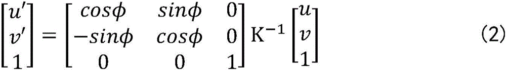
eliminating the roll angle and the vertical and horizontal phase difference of the visual image, and taking the center of the optical axis as the origin of coordinates:

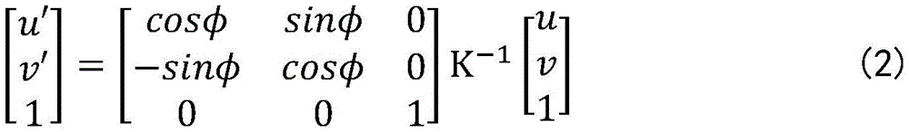
identifying a runway edge and a center line in the visual image, regarding the runway edge as two straight lines, determining an intersection point of the two runway edge lines in the visual image as an infinite projection point, and setting the intersection point as P (u' p ,v′ p ) Then, the yaw angle and the pitch angle of the camera unit relative to the runway are respectively:
Δθ=--atanv′ p
Δψ=--atan(u′ p cosΔθ);
and then eliminating the pitch angle and the yaw angle of the camera unit relative to the runway in the visual image through transformation:
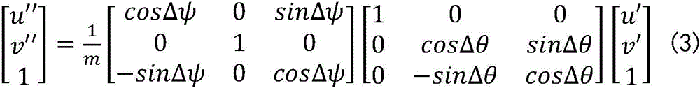
thereby obtaining a transformation image of the optical axis of the camera unit parallel to the runway direction;
where m = cos Δ ψ (cos Δ θ -v 'sin Δ θ) -u' sin Δ ψ such that the third component of the vector is equal to 1.
Preferably, when the actual width of the runway is known, the method further comprises the step of obtaining the offset distance of the airplane relative to the centerline of the runway, and specifically comprises the following steps:
determining relative installation positions of a camera unit and an aircraft;
acquiring the offset distance of the viewpoint of the camera unit relative to the center line of the runway;
and acquiring the offset distance of the airplane relative to the runway center line according to the offset distance between the camera unit view point and the runway center line and the relative installation positions of the camera unit and the aircraft.
Preferably, the step of acquiring the offset distance of the viewpoint of the imaging unit with respect to the runway centerline includes the steps of:
in transforming an image, according to the formula:

the offset distance of the viewpoint of the camera shooting unit relative to the center line of the runway is obtained;
wherein S is o And s is the distance between the intersection point C of the horizontal line and the runway centerline and the intersection point D of the horizontal line and the vertical line in the converted image.
Preferably, the relative installation positions of the camera unit and the aircraft are as follows: when the camera unit is installed on the middle surface of the aircraft, the offset distance of the viewpoint of the camera unit relative to the runway center line is the offset distance of the aircraft relative to the runway center line.
Preferably, when the aircraft is in the flight attitude and the actual width of the runway is known, the method further comprises the following steps:
determining the height difference between the viewpoint of the camera unit and the landing gear of the aircraft;
and judging whether the undercarriage is off the ground or not when the aircraft takes off or whether the undercarriage is grounded or not when the aircraft lands according to the height of the viewpoint of the camera unit relative to the runway.
Preferably, the camera unit is a forward looking camera.
The invention also provides an unmanned aerial vehicle visual positioning device based on the airport runway, which comprises:
the camera shooting unit is used for acquiring a runway visual image;
the visual analysis module is used for establishing a mapping relation between a visual image and a coordinate system of the camera unit; the visual analysis module is also used for acquiring the attitude information of the camera shooting unit, then identifying the side lines and the central lines of the two sides of the runway in the visual image, and transforming the obtained runway visual image according to the mapping relation between the attitude information of the camera shooting unit, the visual image and the camera shooting unit coordinate system to obtain a transformed image of which the optical axis of the camera shooting unit is parallel to the runway direction;
the processing module is used for taking the starting point of the lowest point of the sideline at one side of the runway as a horizontal line in the obtained conversion image, and the horizontal line and the straight line where the sidelines at two sides of the runway are located are respectively intersected at the point A and the point B; the intersection point of straight lines of two side lines of the runway is regarded as a projection point at infinity, and the intersection point is taken as a starting point to be taken as a vertical line intersected with the horizontal line; then according to the formula When the actual width of the runway is known, the height of a camera shooting unit viewpoint relative to the runway is obtained;
wherein H o H is the length of the perpendicular bisector of the transformed image, w is the actual width of the runway, and d is the length of the AB section on the horizontal line in the transformed image.
Due to the adoption of the technical scheme, the invention has the beneficial effects that:
the invention realizes the visual positioning of the unmanned aerial vehicle through the runway information and the runway visual image obtained by the camera unit, does not need to add additional equipment, does not need to require airport facilities, does not need to rely on an external signal source, avoids the interference from the outside, and compared with the positioning method in the traditional mode, the invention effectively simplifies the system and reduces the implementation cost.
Drawings
In order to more clearly illustrate the technical solutions of the embodiments of the present invention, the drawings in the embodiments will be briefly described below, it should be understood that the following drawings only illustrate some embodiments of the present invention, and therefore should not be considered as limiting the scope, and for those skilled in the art, other related drawings can be obtained according to the drawings without inventive efforts.
Fig. 1 is a transformed image obtained after transformation in embodiment 1 of the present invention.
Description of the reference numerals:
1-sideline, 2-midline.
Detailed Description
In order to make the objects, technical solutions and advantages of the embodiments of the present invention clearer, the technical solutions in the embodiments of the present invention will be clearly and completely described below with reference to the drawings in the embodiments of the present invention, and it is obvious that the described embodiments are some, but not all, embodiments of the present invention. The components of embodiments of the present invention generally described and illustrated in the figures herein may be arranged and designed in a wide variety of different configurations.
Thus, the following detailed description of the embodiments of the present invention, as presented in the figures, is not intended to limit the scope of the invention, as claimed, but is merely representative of selected embodiments of the invention. All other embodiments, which can be obtained by a person skilled in the art without making any creative effort based on the embodiments in the present invention, belong to the protection scope of the present invention.
It should be noted that: like reference numbers and letters refer to like items in the following figures, and thus, once an item is defined in one figure, it need not be further defined and explained in subsequent figures.
In the description of the present invention, it should be noted that, if the terms "center", "upper", "lower", "left", "right", "vertical", "horizontal", "inner", "outer", etc. indicate orientations or positional relationships based on the orientations or positional relationships shown in the drawings or the orientations or positional relationships that the products of the present invention are usually placed in when used, the terms are only used for convenience of describing the present invention and simplifying the description, and do not indicate or imply that the devices or elements indicated must have a specific orientation, be constructed in a specific orientation, and be operated, and thus, should not be construed as limiting the present invention. Furthermore, the appearances of the terms "first," "second," and the like in the description of the present invention are not intended to be limiting but rather are to be construed as indicating or implying relative importance.
Furthermore, the terms "horizontal", "vertical" and the like when used in the description of the present invention do not require that the components be absolutely horizontal or overhanging, but may be slightly inclined. For example, "horizontal" merely means that the direction is more horizontal than "vertical" and does not mean that the structure must be perfectly horizontal, but may be slightly inclined.
In the description of the present invention, it should be further noted that unless otherwise explicitly stated or limited, the terms "disposed," "mounted," "connected," and "connected" should be interpreted broadly, and may be, for example, fixedly connected, detachably connected, or integrally connected; can be mechanically or electrically connected; they may be connected directly or indirectly through intervening media, or they may be interconnected between two elements. The specific meanings of the above terms in the present invention can be understood in specific cases to those skilled in the art.
Example 1
The embodiment provides an unmanned aerial vehicle visual positioning method based on an airport runway, which comprises the following steps:
acquiring a runway visual image by using a camera unit;
establishing a mapping relation between a visual image and a coordinate system of a camera unit;
acquiring attitude information of a camera unit, identifying sidelines and central lines on two sides of a runway in a visual image, and transforming the obtained runway visual image according to the mapping relation between the attitude information of the camera unit, the visual image and a camera unit coordinate system to obtain a transformed image of which the optical axis of the camera unit is parallel to the direction of the runway;
in the converted image, the starting point of the lowest point of the sideline on one side of the runway is taken as a horizontal line, and the horizontal line and the straight line where the sidelines on the two sides of the runway are located are respectively intersected at the point A and the point B; the intersection point of straight lines of two side lines of the runway is regarded as a projection point at infinity, and the intersection point is taken as a starting point to be taken as a vertical line intersected with the horizontal line;
according to the formula When the actual width of the runway is known, the height of a camera shooting unit viewpoint relative to the runway is obtained; then judging whether the aircraft takes off or lands according to the height of the camera unit relative to the runway;
wherein H o H is the height of the viewpoint of the camera unit relative to the runway, w is the length of the perpendicular bisector of the converted image, w is the actual width of the runway, and d is the length of the AB section on the horizontal line in the converted image.
Referring to fig. 1, in the embodiment, the height of the camera viewpoint relative to the runway can be obtained by calculating the line segment relationship in the transformed image, and whether the aircraft is off the ground or grounded is determined according to the height, so that the positioning of the unmanned aerial vehicle is realized.
In this embodiment, the drone is in flight attitude, and the actual width of the runway is known. Meanwhile, if the aircraft is parked in an unfamiliar take-off and landing environment, namely when the height of the viewpoint of the camera unit relative to the runway can be easily obtained and the actual width of the runway is unknown, the formula is followed And obtaining the actual width of the runway.
Meanwhile, the attitude information of the camera unit includes a pitch angle θ, a yaw angle ψ, and a roll angle Φ of the camera unit. In this embodiment, the positional relationship between the camera unit and the aircraft is fixed, so the pitch angle θ, yaw angle ψ, and roll angle Φ of the aircraft are the attitude information of the camera unit. The implementer can obtain the attitude information of the camera unit by acquiring the pitch angle theta, the yaw angle psi and the roll angle phi of the aircraft in real time.
More specifically, in this embodiment, the step of establishing a mapping relationship between the visual image and the coordinate system of the camera unit specifically includes the steps of:
defining a coordinate system Oxyz of the camera unit by taking an x axis as the horizontal direction of the camera unit, a y axis as the vertical direction of the camera unit and a z axis as the optical axis direction of the camera unit; an object point located at (x, y, z) in the coordinate system is located at (u, v) on the visual image, then:

wherein u is 0 、v 0 、f x 、f y And K is an internal reference matrix of the camera unit.
The step of obtaining the attitude information of the camera unit and identifying the sidelines and the central lines at two sides of the runway in the visual image, then transforming the obtained runway visual image according to the mapping relation of the attitude information of the camera unit, the visual image and the camera unit coordinate system, and obtaining the transformed image of the camera unit with the optical axis parallel to the runway direction, comprises the following steps:
fixing the camera shooting unit with the aircraft, and acquiring real-time attitude information of the aircraft by the aircraft so as to acquire the real-time attitude information of the camera shooting unit;
eliminating the rolling angle and the vertical and horizontal phase difference of the visual image, and taking the center of the optical axis as the origin of coordinates:
recognizing a runway borderline and a center line in the visual image, regarding the runway borderline as two straight lines, setting the intersection point of the two runway borderlines in the visual image to be an infinite projection point, and setting the intersection point to be P (u' p ,v′ p ) Then, the yaw angle and the pitch angle of the camera unit relative to the runway are respectively:
Δθ=--atanv′ p
Δψ=--atan(u′ p cosΔθ);
and then eliminating the pitch angle and the yaw angle of the camera unit relative to the runway in the visual image through transformation:

thereby obtaining a transformation image of the optical axis of the camera unit parallel to the runway direction;
where m = cos Δ ψ (cos Δ θ -v 'sin Δ θ) -u' sin Δ ψ such that the third component of the vector is equal to 1.
In addition, for the positioning of the drone, in addition to the height of the camera viewpoint relative to the runway, the offset of the aircraft relative to the runway centerline is an important parameter. In this embodiment, the actual width of the runway is known, so that the method further includes the step of obtaining the offset distance of the aircraft relative to the centerline of the runway, and specifically includes the following steps:
determining relative installation positions of a camera unit and an aircraft;
acquiring the offset distance of the viewpoint of the camera unit relative to the center line of the runway;
and acquiring the offset distance of the airplane relative to the runway center line according to the offset distance between the camera unit view point and the runway center line and the relative installation positions of the camera unit and the aircraft.
The step of obtaining the offset distance of the viewpoint of the camera unit relative to the central line of the runway comprises the following steps:
in transforming an image, according to the formula:
the offset distance of the viewpoint of the camera shooting unit relative to the center line of the runway is obtained;
wherein S is o The offset distance of the viewpoint of the camera unit relative to the center line of the runway is set as s, and the distance between the intersection point C of the horizontal line and the center line of the runway and the intersection point D of the horizontal line and the vertical line in the converted image is set as s; d is the length of the AB segment on the horizontal line in the transformed image.
In this embodiment, the relative installation position of the camera unit and the aircraft is that the camera unit is installed on the middle plane of the aircraft, and the offset distance between the viewpoint of the camera unit and the centerline of the runway is the offset distance between the aircraft and the centerline of the runway. Wherein, above-mentioned well face indicates unmanned aerial vehicle at its symmetrical plane of direction bilateral symmetry that moves ahead promptly.
In addition, after acquiring the height of the viewpoint of the camera unit relative to the runway, in order to further more directly realize the positioning of the unmanned aerial vehicle, in this embodiment, the method further includes the following steps:
determining the height difference between the viewpoint of the camera unit and the landing gear of the aircraft;
and judging whether the undercarriage is off the ground or not when the aircraft takes off or whether the undercarriage is grounded or not when the aircraft lands according to the height of the viewpoint of the camera unit relative to the runway. In particular by the magnitude of the higher contrast.
Wherein, because the structure of the aircraft is fixed, the height difference between the viewpoint of the camera unit and the landing gear of the aircraft is easy to know. The implementation personnel can know the specific state of the aircraft during taking off and landing according to the height difference between the camera unit sight point and the runway.
In this embodiment, the camera units are all forward-looking cameras, which are located on the front middle plane of the unmanned aerial vehicle, and the forward-looking cameras are standard configurations of most unmanned aerial vehicles, and no additional equipment is required to be added by using the forward-looking cameras.
The above description is only a preferred embodiment of the present invention and is not intended to limit the present invention, and various modifications and changes may be made by those skilled in the art. Any modification, equivalent replacement, or improvement made within the spirit and principle of the present invention should be included in the protection scope of the present invention.
Claims (7)
1. An unmanned aerial vehicle visual positioning method based on an airport runway is characterized by comprising the following steps:
acquiring a runway visual image by using a camera unit;
establishing a mapping relation between a visual image and a coordinate system of a camera unit;
acquiring the attitude information of a camera unit, identifying side lines and center lines on two sides of a runway in a visual image, and converting the obtained runway visual image according to the mapping relation between the attitude information of the camera unit, the visual image and a camera unit coordinate system to obtain a converted image of which the optical axis of the camera unit is parallel to the direction of the runway;
in the converted image, the starting point of the lowest point of the sideline on one side of the runway is taken as a horizontal line, and the horizontal line and the straight line where the sidelines on the two sides of the runway are located are respectively intersected at the point A and the point B; the intersection point of straight lines of two side lines of the runway is regarded as a projection point at infinity, and the intersection point is taken as a starting point to be taken as a vertical line intersected with the horizontal line;
according to the formula When the actual width of the runway is known, the height of the viewpoint of the camera unit relative to the runway is obtained; then judging whether the aircraft takes off or lands according to the height of the viewpoint of the camera unit relative to the runway;
or according to a formula When the height of the camera shooting unit viewpoint relative to the runway is known, the actual width of the runway is obtained;
wherein H o The height of a camera unit viewpoint relative to a runway is shown, h is the length of a perpendicular bisector of the converted image, w is the actual width of the runway, and d is the length of an AB section on a horizontal line in the converted image;
the attitude information of the camera shooting unit comprises a pitch angle theta, a yaw angle psi and a roll angle phi of the camera shooting unit;
the step of establishing the mapping relation between the visual image and the coordinate system of the camera unit comprises the following steps:
defining a coordinate system Oxyz of the camera unit by taking an x axis as the horizontal direction of the camera unit, a y axis as the vertical direction of the camera unit and a z axis as the optical axis direction of the camera unit; an object point located at (x, y, z) in the coordinate system is located at (u, v) on the visual image, then:

wherein u is 0 、v 0 、f x 、f y Is an internal reference of the camera shooting unit, and K is an internal reference matrix of the camera shooting unit;
the step of obtaining the attitude information of the camera unit and identifying the sidelines and the center lines at two sides of the runway in the visual image, then transforming the obtained runway visual image according to the mapping relation of the attitude information of the camera unit, the visual image and the camera unit coordinate system to obtain a transformed image of which the optical axis of the camera unit is parallel to the runway direction, comprises the following steps of:
fixing the camera shooting unit with the aircraft, and acquiring real-time attitude information of the aircraft by the aircraft so as to acquire the real-time attitude information of the camera shooting unit;
eliminating the roll angle and the vertical and horizontal phase difference of the visual image, and taking the center of the optical axis as the origin of coordinates:

identifying a runway edge and a center line in the visual image, regarding the runway edge as two straight lines, determining an intersection point of the two runway edge lines in the visual image as an infinite projection point, and setting the intersection point as P (u' p ,v′ p ) Then, the yaw angle and the pitch angle of the camera unit relative to the runway are respectively:
Δθ=-atanv′ p
Δψ=-atan(u′ p cosΔθ);
and then eliminating the pitch angle and the yaw angle of the camera unit relative to the runway in the visual image through transformation:

thereby obtaining a transformation image of the optical axis of the camera unit parallel to the runway direction;
where m = cos Δ ψ (cos Δ θ -v 'sin Δ θ) -u' sin Δ ψ such that the third component of the vector is equal to 1.
2. The visual positioning method of the unmanned aerial vehicle based on the airport runway according to claim 1, wherein the step of obtaining the offset distance of the airplane relative to the centerline of the runway specifically comprises the following steps:
determining relative installation positions of a camera unit and an aircraft;
acquiring the offset distance of the viewpoint of the camera unit relative to the center line of the runway;
and acquiring the offset distance of the airplane relative to the runway center line according to the offset distance between the camera unit view point and the runway center line and the relative installation positions of the camera unit and the aircraft.
3. The visual positioning method for unmanned aerial vehicle based on airport runway according to claim 2, wherein the step of obtaining the offset distance of the view point of the camera unit relative to the centerline of the runway comprises the steps of:
in transforming an image, according to the formula:

the offset distance of the viewpoint of the camera shooting unit relative to the center line of the runway is obtained;
wherein S is o And s is the distance between the intersection point C of the horizontal line and the runway center line and the intersection point D of the horizontal line and the vertical line in the converted image.
4. The visual positioning method for unmanned aerial vehicle based on airport runway according to claim 3, characterized in that the relative installation positions of the camera unit and the aircraft are as follows: when the camera unit is installed on the middle surface of the aircraft, the offset distance of the viewpoint of the camera unit relative to the center line of the runway is the offset distance of the aircraft relative to the center line of the runway.
5. The visual positioning method for unmanned aerial vehicle based on airport runway according to claim 1, characterized in that when the aircraft is in flight attitude and the actual width of the runway is known, it further comprises the steps of:
determining the height difference between the viewpoint of the camera unit and the landing gear of the aircraft;
and judging whether the undercarriage is off the ground or not when the aircraft takes off or whether the undercarriage is grounded or not when the aircraft lands according to the height of the viewpoint of the camera unit relative to the runway.
6. The visual positioning method for unmanned aerial vehicle based on airport runway according to claim 1, characterized in that the camera unit is a forward looking camera.
7. The utility model provides an unmanned aerial vehicle vision positioner based on airport runway which characterized in that includes:
the camera shooting unit is used for acquiring a runway visual image;
the visual analysis module is used for establishing a mapping relation between a visual image and a camera unit coordinate system; the visual analysis module is also used for acquiring the attitude information of the camera unit, identifying the sidelines and the center lines at two sides of the runway in the visual image, and transforming the obtained runway visual image according to the mapping relation between the attitude information of the camera unit, the visual image and the camera unit coordinate system to obtain a transformed image of which the optical axis of the camera unit is parallel to the runway direction;
the attitude information of the camera shooting unit comprises a pitch angle theta, a yaw angle psi and a roll angle phi of the camera shooting unit;
the method for establishing the mapping relation between the visual image and the coordinate system of the camera unit comprises the following steps:
defining a coordinate system Oxyz of the camera unit by taking an x axis as the horizontal direction of the camera unit, a y axis as the vertical direction of the camera unit and a z axis as the optical axis direction of the camera unit; an object point located at (x, y, z) in the coordinate system is located at (u, v) on the visual image, then:

wherein u is 0 、v 0 、f x 、f y Is an internal reference of the camera shooting unit, and K is an internal reference matrix of the camera shooting unit;
the method comprises the following steps of acquiring the attitude information of a camera unit, identifying side lines and center lines at two sides of a runway in a visual image, and then transforming the visual image of the runway according to the mapping relation between the attitude information of the camera unit, the visual image and a camera unit coordinate system to obtain a transformed image of which the optical axis of the camera unit is parallel to the direction of the runway, and comprises the following steps:
fixing the camera shooting unit with the aircraft, and acquiring real-time attitude information of the aircraft by the aircraft so as to acquire the real-time attitude information of the camera shooting unit;
eliminating the roll angle and the vertical and horizontal phase difference of the visual image, and taking the center of the optical axis as the origin of coordinates:
recognizing a runway borderline and a center line in the visual image, regarding the runway borderline as two straight lines, setting the intersection point of the two runway borderlines in the visual image to be an infinite projection point, and setting the intersection point to be P (u' p ,v′ p ) Then, the yaw angle and the pitch angle of the camera unit relative to the runway are respectively:
Δθ=-atanv′ p
Δψ=-atan(u′ p cosΔθ);
and then eliminating the pitch angle and the yaw angle of the camera unit relative to the runway in the visual image through transformation:

thereby obtaining a transformation image of the optical axis of the camera unit parallel to the runway direction;
wherein m = cos Δ ψ (cos Δ θ -v 'sin Δ θ) -u' sin Δ ψ such that the third component of the vector is equal to 1;
the processing module is used for taking the starting point of the lowest point of the sideline at one side of the runway as a horizontal line in the obtained conversion image, and the horizontal line and the straight line where the sidelines at two sides of the runway are located are respectively intersected at the point A and the point B; the intersection point of straight lines of two side lines of the runway is regarded as a projection point at infinity, and the intersection point is taken as a starting point to be taken as a vertical line intersected with the horizontal line; then according to the formula When the actual width of the runway is known, the height of the viewpoint of the camera unit relative to the runway is obtained; then, judging whether the aircraft takes off or lands according to the height of the viewpoint of the camera unit relative to the runway;
wherein H o H is the height of the viewpoint of the camera unit relative to the runway, w is the length of the perpendicular bisector of the converted image, w is the actual width of the runway, and d is the length of the AB section on the horizontal line in the converted image.
Priority Applications (1)
| Application Number | Priority Date | Filing Date | Title |
|---|---|---|---|
| CN202110439124.XA CN113295164B (en) | 2021-04-23 | 2021-04-23 | Unmanned aerial vehicle visual positioning method and device based on airport runway |
Applications Claiming Priority (1)
| Application Number | Priority Date | Filing Date | Title |
|---|---|---|---|
| CN202110439124.XA CN113295164B (en) | 2021-04-23 | 2021-04-23 | Unmanned aerial vehicle visual positioning method and device based on airport runway |
Publications (2)
| Publication Number | Publication Date |
|---|---|
| CN113295164A CN113295164A (en) | 2021-08-24 |
| CN113295164B true CN113295164B (en) | 2022-11-04 |
Family
ID=77320131
Family Applications (1)
| Application Number | Title | Priority Date | Filing Date |
|---|---|---|---|
| CN202110439124.XA Active CN113295164B (en) | 2021-04-23 | 2021-04-23 | Unmanned aerial vehicle visual positioning method and device based on airport runway |
Country Status (1)
| Country | Link |
|---|---|
| CN (1) | CN113295164B (en) |
Families Citing this family (4)
| Publication number | Priority date | Publication date | Assignee | Title |
|---|---|---|---|---|
| CN113932804B (en) * | 2021-09-17 | 2024-08-30 | 四川腾盾科技有限公司 | Positioning method combining airport runway vision and GNSS/inertial navigation |
| CN115439761B (en) * | 2022-07-22 | 2025-10-03 | 北京理工大学 | A method for autonomous guided landing of UAV based on monocular vision navigation |
| CN115686033A (en) * | 2022-11-16 | 2023-02-03 | 亿航智能设备(广州)有限公司 | Fixed-wing unmanned aerial vehicle landing method, fixed-wing unmanned aerial vehicle and storage medium |
| CN117115598B (en) * | 2023-08-17 | 2024-08-06 | 北京自动化控制设备研究所 | Visual line feature extraction precision evaluation method |
Citations (1)
| Publication number | Priority date | Publication date | Assignee | Title |
|---|---|---|---|---|
| CN104833338A (en) * | 2013-06-21 | 2015-08-12 | 杭州海存信息技术有限公司 | Visual-based airplane landing assistant device |
Family Cites Families (22)
| Publication number | Priority date | Publication date | Assignee | Title |
|---|---|---|---|---|
| GB1002553A (en) * | 1962-01-08 | 1965-08-25 | Sperry Rand Corp | Navigation instrument |
| JP3005682B1 (en) * | 1999-01-11 | 2000-01-31 | 科学技術庁航空宇宙技術研究所長 | Method and apparatus for determining position / posture using runway image |
| CN101850849B (en) * | 2010-05-18 | 2013-11-06 | 清华大学 | Positioning system and positioning method for take-off deviation of airplane |
| WO2012115594A1 (en) * | 2011-02-21 | 2012-08-30 | Stratech Systems Limited | A surveillance system and a method for detecting a foreign object, debris, or damage in an airfield |
| US8589071B2 (en) * | 2011-08-15 | 2013-11-19 | Honeywell International Inc. | Aircraft vision system including a runway position indicator |
| CN104006790A (en) * | 2013-02-21 | 2014-08-27 | 成都海存艾匹科技有限公司 | Vision-Based Aircraft Landing Aids |
| FR3009117B1 (en) * | 2013-07-24 | 2016-11-25 | Airbus Operations Sas | AUTONOMOUS AUTOMATIC LANDING METHOD AND SYSTEM |
| US9174746B1 (en) * | 2014-06-26 | 2015-11-03 | Rockwell Collins, Inc. | Visual aid generating system, device, and method |
| FR3024127B1 (en) * | 2014-07-25 | 2016-08-26 | Airbus Operations Sas | AUTONOMOUS AUTOMATIC LANDING METHOD AND SYSTEM |
| FR3044809B1 (en) * | 2015-12-03 | 2017-11-24 | Airbus Operations Sas | METHOD AND SYSTEM FOR AIDING THE LANDING OF AN AIRCRAFT. |
| CN108225273B (en) * | 2016-12-14 | 2020-06-30 | 中国航空工业集团公司西安航空计算技术研究所 | Real-time runway detection method based on sensor priori knowledge |
| CN106990776B (en) * | 2017-02-27 | 2020-08-11 | 广东省智能制造研究所 | Robot homing positioning method and system |
| CN107202982B (en) * | 2017-05-22 | 2018-08-07 | 徐泽宇 | A kind of beacon arrangement and image processing method based on UAV position and orientation calculating |
| CN107478215B (en) * | 2017-07-26 | 2020-11-06 | 中国人民解放军空军勤务学院 | Runway azimuth angle-based positioning method for photometric characteristic detector of airport navigation aid lamp |
| CN109116866B (en) * | 2018-09-20 | 2021-05-14 | 四川腾盾科技有限公司 | Bidirectional autonomous driving-in control method for unmanned aerial vehicle |
| CN109341700B (en) * | 2018-12-04 | 2023-06-30 | 中国航空工业集团公司西安航空计算技术研究所 | Visual auxiliary landing navigation method for fixed-wing aircraft under low visibility |
| CN109544696B (en) * | 2018-12-04 | 2022-12-20 | 中国航空工业集团公司西安航空计算技术研究所 | Accurate registration method for airborne enhanced synthetic visual virtual and real images based on visual inertial combination |
| CN109871628B (en) * | 2019-02-27 | 2021-03-09 | 北京航空航天大学 | Simulation computing system and method for evaluating seaworthiness compliance of amphibious aircraft |
| US11532237B2 (en) * | 2019-02-28 | 2022-12-20 | Rockwell Collins, Inc. | Autonomous aircraft sensor-based positioning and navigation system using markers |
| CN110018170B (en) * | 2019-04-15 | 2021-08-13 | 中国民航大学 | A method for locating small damage to aircraft skin based on honeycomb model |
| CN110108894B (en) * | 2019-04-26 | 2020-07-21 | 北京航空航天大学 | A Multi-rotor Velocity Measurement Method Based on Phase Correlation and Optical Flow Method |
| CN112686149B (en) * | 2020-12-29 | 2024-03-19 | 中国航天空气动力技术研究院 | Vision-based near-zone autonomous landing method of fixed-wing unmanned aerial vehicle |
-
2021
- 2021-04-23 CN CN202110439124.XA patent/CN113295164B/en active Active
Patent Citations (1)
| Publication number | Priority date | Publication date | Assignee | Title |
|---|---|---|---|---|
| CN104833338A (en) * | 2013-06-21 | 2015-08-12 | 杭州海存信息技术有限公司 | Visual-based airplane landing assistant device |
Non-Patent Citations (1)
| Title |
|---|
| 固定翼飞行器自主着陆中视觉算法的研究;徐宽等;《电子设计工程》;20160905;第24卷(第17期);第35-38页 * |
Also Published As
| Publication number | Publication date |
|---|---|
| CN113295164A (en) | 2021-08-24 |
Similar Documents
| Publication | Publication Date | Title |
|---|---|---|
| CN113295164B (en) | Unmanned aerial vehicle visual positioning method and device based on airport runway | |
| US11749126B2 (en) | Landing site localization for dynamic control of an aircraft toward a landing site | |
| RU2666479C1 (en) | Method of providing the automatic landing of the flying apparatus | |
| US10935987B2 (en) | Landing site localization for dynamic control of an aircraft toward a landing site | |
| KR101494654B1 (en) | Method and Apparatus for Guiding Unmanned Aerial Vehicle and Method and Apparatus for Controlling Unmanned Aerial Vehicle | |
| US11126201B2 (en) | Image sensor based autonomous landing | |
| US6889941B1 (en) | Aircraft formation/refueling guidance system | |
| US7693617B2 (en) | Aircraft precision approach control | |
| RU2703412C2 (en) | Automatic aircraft landing method | |
| CN103092211B (en) | Unmanned aerial vehicle emergent land method based on guidance of radio and laser | |
| CN108255190B (en) | Accurate landing method based on multiple sensors and tethered unmanned aerial vehicle using same | |
| GB2224613A (en) | Navigation using triangle of light sources | |
| US12498718B2 (en) | Landing site localization for dynamic control of an aircraft toward a landing site | |
| KR20100027747A (en) | Automatic landing system and control method using circular image data for aircraft | |
| US20190088146A1 (en) | Method and a device for avoiding an object by detecting its approach to an aircraft | |
| JP2662111B2 (en) | Automatic landing guidance method for vertical take-off and landing aircraft | |
| CN103149938A (en) | Emergency landing method of unmanned aerial vehicle based on radio and laser guiding | |
| CN118192640A (en) | Unmanned aerial vehicle accurate landing control system | |
| CN113212789A (en) | Auxiliary system for airplane taxiing | |
| US12530980B2 (en) | Method for identifying a landing zone, computer program and electronic device therefor | |
| CN112797982A (en) | Unmanned aerial vehicle autonomous landing measurement method based on machine vision | |
| CN113932804B (en) | Positioning method combining airport runway vision and GNSS/inertial navigation | |
| RU2773978C1 (en) | Method for accurate landing of an unmanned aerial vehicle and device for implementing the method | |
| RU2055785C1 (en) | Aircraft landing method | |
| RU2578202C1 (en) | Method for helicopter navigation, takeoff and landing |
Legal Events
| Date | Code | Title | Description |
|---|---|---|---|
| PB01 | Publication | ||
| PB01 | Publication | ||
| SE01 | Entry into force of request for substantive examination | ||
| SE01 | Entry into force of request for substantive examination | ||
| GR01 | Patent grant | ||
| GR01 | Patent grant |