[go: up one dir, main page]

CN113287039A - Detachable automobile LIDAR data collection pod - Google Patents

Detachable automobile LIDAR data collection pod Download PDF

Info

Publication number
CN113287039A
CN113287039A CN201980071453.4A CN201980071453A CN113287039A CN 113287039 A CN113287039 A CN 113287039A CN 201980071453 A CN201980071453 A CN 201980071453A CN 113287039 A CN113287039 A CN 113287039A
Authority
CN
China
Prior art keywords
vehicle
data
detachable
pod
computing device
Prior art date
Legal status (The legal status is an assumption and is not a legal conclusion. Google has not performed a legal analysis and makes no representation as to the accuracy of the status listed.)
Pending
Application number
CN201980071453.4A
Other languages
Chinese (zh)
Inventor
纳撒尼尔·吉斯特四世
克里斯托弗·威廉姆斯
Current Assignee (The listed assignees may be inaccurate. Google has not performed a legal analysis and makes no representation or warranty as to the accuracy of the list.)
Aurora Innovation Opco
Original Assignee
Aurora Innovation Inc
Priority date (The priority date is an assumption and is not a legal conclusion. Google has not performed a legal analysis and makes no representation as to the accuracy of the date listed.)
Filing date
Publication date
Application filed by Aurora Innovation Inc filed Critical Aurora Innovation Inc
Publication of CN113287039A publication Critical patent/CN113287039A/en
Pending legal-status Critical Current

Links

Images

Classifications

    • GPHYSICS
    • G05CONTROLLING; REGULATING
    • G05DSYSTEMS FOR CONTROLLING OR REGULATING NON-ELECTRIC VARIABLES
    • G05D1/00Control of position, course, altitude or attitude of land, water, air or space vehicles, e.g. using automatic pilots
    • G05D1/02Control of position or course in two dimensions
    • G05D1/021Control of position or course in two dimensions specially adapted to land vehicles
    • G05D1/0231Control of position or course in two dimensions specially adapted to land vehicles using optical position detecting means
    • BPERFORMING OPERATIONS; TRANSPORTING
    • B60VEHICLES IN GENERAL
    • B60RVEHICLES, VEHICLE FITTINGS, OR VEHICLE PARTS, NOT OTHERWISE PROVIDED FOR
    • B60R11/00Arrangements for holding or mounting articles, not otherwise provided for
    • B60R11/04Mounting of cameras operative during drive; Arrangement of controls thereof relative to the vehicle
    • GPHYSICS
    • G01MEASURING; TESTING
    • G01SRADIO DIRECTION-FINDING; RADIO NAVIGATION; DETERMINING DISTANCE OR VELOCITY BY USE OF RADIO WAVES; LOCATING OR PRESENCE-DETECTING BY USE OF THE REFLECTION OR RERADIATION OF RADIO WAVES; ANALOGOUS ARRANGEMENTS USING OTHER WAVES
    • G01S17/00Systems using the reflection or reradiation of electromagnetic waves other than radio waves, e.g. lidar systems
    • G01S17/86Combinations of lidar systems with systems other than lidar, radar or sonar, e.g. with direction finders
    • GPHYSICS
    • G01MEASURING; TESTING
    • G01SRADIO DIRECTION-FINDING; RADIO NAVIGATION; DETERMINING DISTANCE OR VELOCITY BY USE OF RADIO WAVES; LOCATING OR PRESENCE-DETECTING BY USE OF THE REFLECTION OR RERADIATION OF RADIO WAVES; ANALOGOUS ARRANGEMENTS USING OTHER WAVES
    • G01S17/00Systems using the reflection or reradiation of electromagnetic waves other than radio waves, e.g. lidar systems
    • G01S17/88Lidar systems specially adapted for specific applications
    • G01S17/93Lidar systems specially adapted for specific applications for anti-collision purposes
    • G01S17/931Lidar systems specially adapted for specific applications for anti-collision purposes of land vehicles
    • GPHYSICS
    • G01MEASURING; TESTING
    • G01SRADIO DIRECTION-FINDING; RADIO NAVIGATION; DETERMINING DISTANCE OR VELOCITY BY USE OF RADIO WAVES; LOCATING OR PRESENCE-DETECTING BY USE OF THE REFLECTION OR RERADIATION OF RADIO WAVES; ANALOGOUS ARRANGEMENTS USING OTHER WAVES
    • G01S7/00Details of systems according to groups G01S13/00, G01S15/00, G01S17/00
    • G01S7/48Details of systems according to groups G01S13/00, G01S15/00, G01S17/00 of systems according to group G01S17/00
    • G01S7/481Constructional features, e.g. arrangements of optical elements
    • G01S7/4811Constructional features, e.g. arrangements of optical elements common to transmitter and receiver
    • G01S7/4813Housing arrangements
    • GPHYSICS
    • G05CONTROLLING; REGULATING
    • G05DSYSTEMS FOR CONTROLLING OR REGULATING NON-ELECTRIC VARIABLES
    • G05D1/00Control of position, course, altitude or attitude of land, water, air or space vehicles, e.g. using automatic pilots
    • G05D1/02Control of position or course in two dimensions
    • G05D1/021Control of position or course in two dimensions specially adapted to land vehicles
    • G05D1/0268Control of position or course in two dimensions specially adapted to land vehicles using internal positioning means
    • G05D1/027Control of position or course in two dimensions specially adapted to land vehicles using internal positioning means comprising intertial navigation means, e.g. azimuth detector
    • GPHYSICS
    • G05CONTROLLING; REGULATING
    • G05DSYSTEMS FOR CONTROLLING OR REGULATING NON-ELECTRIC VARIABLES
    • G05D1/00Control of position, course, altitude or attitude of land, water, air or space vehicles, e.g. using automatic pilots
    • G05D1/02Control of position or course in two dimensions
    • G05D1/021Control of position or course in two dimensions specially adapted to land vehicles
    • G05D1/0276Control of position or course in two dimensions specially adapted to land vehicles using signals provided by a source external to the vehicle
    • G05D1/0278Control of position or course in two dimensions specially adapted to land vehicles using signals provided by a source external to the vehicle using satellite positioning signals, e.g. GPS
    • GPHYSICS
    • G05CONTROLLING; REGULATING
    • G05DSYSTEMS FOR CONTROLLING OR REGULATING NON-ELECTRIC VARIABLES
    • G05D1/00Control of position, course, altitude or attitude of land, water, air or space vehicles, e.g. using automatic pilots
    • G05D1/20Control system inputs
    • G05D1/24Arrangements for determining position or orientation
    • G05D1/245Arrangements for determining position or orientation using dead reckoning
    • GPHYSICS
    • G05CONTROLLING; REGULATING
    • G05DSYSTEMS FOR CONTROLLING OR REGULATING NON-ELECTRIC VARIABLES
    • G05D1/00Control of position, course, altitude or attitude of land, water, air or space vehicles, e.g. using automatic pilots
    • G05D1/20Control system inputs
    • G05D1/24Arrangements for determining position or orientation
    • G05D1/247Arrangements for determining position or orientation using signals provided by artificial sources external to the vehicle, e.g. navigation beacons
    • G05D1/248Arrangements for determining position or orientation using signals provided by artificial sources external to the vehicle, e.g. navigation beacons generated by satellites, e.g. GPS
    • GPHYSICS
    • G05CONTROLLING; REGULATING
    • G05DSYSTEMS FOR CONTROLLING OR REGULATING NON-ELECTRIC VARIABLES
    • G05D1/00Control of position, course, altitude or attitude of land, water, air or space vehicles, e.g. using automatic pilots
    • G05D1/20Control system inputs
    • G05D1/24Arrangements for determining position or orientation
    • G05D1/247Arrangements for determining position or orientation using signals provided by artificial sources external to the vehicle, e.g. navigation beacons
    • G05D1/249Arrangements for determining position or orientation using signals provided by artificial sources external to the vehicle, e.g. navigation beacons from positioning sensors located off-board the vehicle, e.g. from cameras
    • GPHYSICS
    • G06COMPUTING OR CALCULATING; COUNTING
    • G06FELECTRIC DIGITAL DATA PROCESSING
    • G06F13/00Interconnection of, or transfer of information or other signals between, memories, input/output devices or central processing units
    • G06F13/38Information transfer, e.g. on bus
    • G06F13/42Bus transfer protocol, e.g. handshake; Synchronisation
    • G06F13/4282Bus transfer protocol, e.g. handshake; Synchronisation on a serial bus, e.g. I2C bus, SPI bus
    • BPERFORMING OPERATIONS; TRANSPORTING
    • B60VEHICLES IN GENERAL
    • B60RVEHICLES, VEHICLE FITTINGS, OR VEHICLE PARTS, NOT OTHERWISE PROVIDED FOR
    • B60R11/00Arrangements for holding or mounting articles, not otherwise provided for
    • B60R2011/0001Arrangements for holding or mounting articles, not otherwise provided for characterised by position
    • B60R2011/004Arrangements for holding or mounting articles, not otherwise provided for characterised by position outside the vehicle
    • BPERFORMING OPERATIONS; TRANSPORTING
    • B60VEHICLES IN GENERAL
    • B60RVEHICLES, VEHICLE FITTINGS, OR VEHICLE PARTS, NOT OTHERWISE PROVIDED FOR
    • B60R11/00Arrangements for holding or mounting articles, not otherwise provided for
    • B60R2011/0042Arrangements for holding or mounting articles, not otherwise provided for characterised by mounting means
    • B60R2011/0049Arrangements for holding or mounting articles, not otherwise provided for characterised by mounting means for non integrated articles
    • B60R2011/0064Connection with the article
    • B60R2011/0068Connection with the article using suction cups
    • BPERFORMING OPERATIONS; TRANSPORTING
    • B60VEHICLES IN GENERAL
    • B60RVEHICLES, VEHICLE FITTINGS, OR VEHICLE PARTS, NOT OTHERWISE PROVIDED FOR
    • B60R11/00Arrangements for holding or mounting articles, not otherwise provided for
    • B60R2011/0042Arrangements for holding or mounting articles, not otherwise provided for characterised by mounting means
    • B60R2011/0049Arrangements for holding or mounting articles, not otherwise provided for characterised by mounting means for non integrated articles
    • B60R2011/0064Connection with the article
    • B60R2011/007Connection with the article using magnetic means
    • GPHYSICS
    • G05CONTROLLING; REGULATING
    • G05DSYSTEMS FOR CONTROLLING OR REGULATING NON-ELECTRIC VARIABLES
    • G05D2111/00Details of signals used for control of position, course, altitude or attitude of land, water, air or space vehicles
    • G05D2111/10Optical signals
    • G05D2111/17Coherent light, e.g. laser signals
    • GPHYSICS
    • G05CONTROLLING; REGULATING
    • G05DSYSTEMS FOR CONTROLLING OR REGULATING NON-ELECTRIC VARIABLES
    • G05D2111/00Details of signals used for control of position, course, altitude or attitude of land, water, air or space vehicles
    • G05D2111/50Internal signals, i.e. from sensors located in the vehicle, e.g. from compasses or angular sensors
    • G05D2111/52Internal signals, i.e. from sensors located in the vehicle, e.g. from compasses or angular sensors generated by inertial navigation means, e.g. gyroscopes or accelerometers
    • GPHYSICS
    • G06COMPUTING OR CALCULATING; COUNTING
    • G06FELECTRIC DIGITAL DATA PROCESSING
    • G06F2213/00Indexing scheme relating to interconnection of, or transfer of information or other signals between, memories, input/output devices or central processing units
    • G06F2213/0002Serial port, e.g. RS232C

Landscapes

  • Engineering & Computer Science (AREA)
  • Physics & Mathematics (AREA)
  • Radar, Positioning & Navigation (AREA)
  • Remote Sensing (AREA)
  • General Physics & Mathematics (AREA)
  • Automation & Control Theory (AREA)
  • Aviation & Aerospace Engineering (AREA)
  • Computer Networks & Wireless Communication (AREA)
  • Theoretical Computer Science (AREA)
  • Electromagnetism (AREA)
  • Mechanical Engineering (AREA)
  • General Engineering & Computer Science (AREA)
  • Traffic Control Systems (AREA)
  • Optical Radar Systems And Details Thereof (AREA)
  • Navigation (AREA)

Abstract

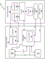
可以使用吊舱安装件的一个或多个腿将与车辆无关的可拆卸吊舱安装在车辆上。可拆卸吊舱可以收集各种环境数据以及车辆数据并为其添加时间戳。例如,可以使用传感器套件来收集环境数据,该传感器套件可以包括IMU、3D定位传感器、一个或多个相机和/或LIDAR单元。作为另一示例,可以经由附接到车辆的CAN总线来收集车辆数据。可以对环境数据和/或车辆数据添加时间戳,并将其传输到远程服务器,以供计算设备进行进一步处理。

Figure 201980071453

A vehicle-independent detachable pod may be mounted on a vehicle using one or more legs of the pod mount. Detachable pods can collect and time stamp various environmental data as well as vehicle data. For example, environmental data may be collected using a sensor suite that may include an IMU, a 3D positioning sensor, one or more cameras, and/or a LIDAR unit. As another example, vehicle data may be collected via a CAN bus attached to the vehicle. Environmental data and/or vehicle data can be time stamped and transmitted to a remote server for further processing by a computing device.

Figure 201980071453

Description

Detachable automobile LIDAR data collection pod
Background
With the continued development of computing and vehicle technology, features related to autonomous driving have become more powerful and widely available, and are able to control vehicles in a wider variety of situations. For example, for automobiles, the automotive industry typically employs SAE international standard J3016, which specifies 6 levels of autopilot. The vehicle without the automatic driving right is designated as level 0. With level 1 autodrive, the vehicle controls either steering or speed (but not both) so that the operator can perform most vehicle functions. With level 2 autodrive authority, the vehicle is able to control steering, speed and braking in limited circumstances (e.g. while driving along a highway), but still requires the operator to remain alert and ready to take over operations, and to handle actions such as any lane changes or turns. Starting from level 3 autonomous driving, the vehicle can manage most of the operating variables, including monitoring the surrounding environment, but still requires the operator to be kept alert and take over the vehicle whenever a situation is encountered that the vehicle cannot handle. Level 4 autopilot provides the ability to operate without operator input, but only under certain conditions, such as only in certain types of roads (e.g., highways) or only in certain geographic areas (e.g., geofenced metropolitan areas that have been adequately mapped). Finally, level 5 autopilot means that the vehicle can be operated without operator input under all conditions.
The fundamental challenges of any autopilot-related technology relate to collecting and interpreting information about the vehicle's surroundings, and to planning and executing commands to appropriately control vehicle motion to safely navigate the vehicle through its current environment. Accordingly, efforts have been made to improve each of these aspects, and in so doing, autonomous vehicles are increasingly able to operate safely and reliably in increasingly complex environments and to accommodate expected and unexpected interactions in the environment.
Disclosure of Invention
Described herein are techniques that enable a method and apparatus to be implemented that includes a vehicle independent detachable pod equipped with a sensor suite and a computing device for collecting and time-stamping data related to the vehicle surroundings as well as data related to the vehicle itself. A sensor suite of detachable pods (also referred to herein as "pods") may collect various environmental data with various sensors including an Inertial Measurement Unit (IMU), a three-dimensional ("3D") positioning sensor (e.g., global positioning system ("GPS")), one or more cameras, a light detection and ranging ("LIDAR") unit, and the like. The detachable pod can also be connected to the vehicle to collect data directly from the car in addition to the data collected by the sensors integrated into the detachable pod. For example, the detachable pods may be connected to a vehicle controller area network ("CAN") bus, such as by being connected to an on-board diagnostics ("OBD") port (e.g., OBDII port) of the vehicle, to gain access to various vehicle data (e.g., vehicle speed data, brake data, steering control data, etc.). Additionally or alternatively, the detachable pods may be powered by the vehicle. For example, the detachable pods may be powered by a DC connector in the vehicle (e.g., a 12 volt vehicle receptacle), a USB port in the vehicle, or various other electrical connections within the vehicle (e.g., vehicle tail lights), etc. In several embodiments, mounting the detachable pods on various vehicles can create greater versatility in environmental data measurements than collecting environmental data using a single vehicle.
A computing device connected to the detachable pod CAN record environmental data collected by the sensor suite as well as vehicle data from the CAN bus. In various embodiments, the computing device may timestamp the data when the data is collected from the environment using a sensor suite integrated in the detachable pod, and/or when the data is collected directly from the vehicle (e.g., vehicle data is collected from a vehicle CAN bus). Additionally or alternatively, the sensor may provide its own timestamp (e.g., the LIDAR unit may generate its own timestamp for the data it collects). In many implementations, the computing device may combine environmental data, vehicle data, and various predefined data sets, such as known information about a particular vehicle with a corresponding timestamp (e.g., when the detachable pod is installed on the vehicle, known information about the color, make, model, etc. of the vehicle is provided by the user) to generate a single data structure. In some such implementations, these data structures may be uploaded to a remote server (i.e., upload data to the cloud) for further remote processing. The processing of the data collected by the sensor suite of the detachable pod (i.e., environmental data) and/or the data collected directly from the vehicle (i.e., vehicle data) with the corresponding time stamp can be performed in real time, near real time, and/or the data can be stored and processed at a later time. In some embodiments, the data collected by the detachable pods may be combined and processed with additional data collected from other sources, such as from one or more additional detachable pods. In other words, data collected from two vehicles having detachable pods mounted at similar locations at the same time may be combined into one data set.
In many embodiments, the detachable pods may be vehicle independent. In other words, the detachable pods can be mounted on many (any for certain detachable pod configurations) vehicle types. For example, the detachable pods may be mounted on automobiles, trucks, motorcycles, sport utility vehicles, vans, mopeds, tractor trailers, buses, electric scooters, and the like. Additionally or alternatively, the detachable pods may be mounted on different vehicles within one vehicle type. For example, automobile manufacturers produce a wide variety of types of automobiles, and removable pods may be installed on many automobiles regardless of their make and model. By allowing the detachable pods to be vehicle independent, a richer set of various data can be collected from various automotive perspectives. Several vehicle independent detachable pods mounted on various vehicles can quickly collect large amounts of data. In other words, data collection can be extended very quickly, for example by passing to a new location and placing a set of detachable pods of rented cars.
In some embodiments, multiple detachable pods may be mounted on a single vehicle. For example, two pods may be mounted on a car towing a trailer (i.e., one detachable pod may be mounted on the car and a second detachable pod may be mounted on the trailer). Sometimes the car and trailer move in different directions (e.g., when the car is backing, etc.), and the data from the car and trailer is useful for further analysis. In an embodiment, a pod attached to a car and a pod attached to a trailer may collect data simultaneously. Multiple pods attached to a single vehicle may be connected to the same computing device to collect and store data. Additionally or alternatively, multiple pods attached to a single vehicle may each engage with their own computing device to collect data, and once the computing device uploads various time-stamped data to the cloud or other storage medium, the data from the multiple detachable pods may be aggregated together.
To analyze the sensor data collected from the detachable pods, it may be important to know the location of the detachable pods on the vehicle. In many embodiments, installing the nacelle includes determining a position of the nacelle and/or determining whether the nacelle is in a valid position. An active position, as used herein, refers to a position where the detachable pod has been mounted on the vehicle such that the sensors in the detachable pod are aligned at a location where the sensors can collect data from a known predetermined angle. In some implementations, a user interface on a computing device can guide a user by positioning a detachable pod on a vehicle. For example, if the desired location of the pod is the center of the roof of an automobile, the user interface may guide the user to find the center of the roof. In many embodiments, a sensor suite within the removable pod may capture data as the user positions the pod. For example, one or more sensors within the removable pod may acquire measurements of the vehicle. In various implementations, a user may provide identifying information about a vehicle (e.g., make, model, year, etc. of an automobile) and may determine measurements of the vehicle from a database stored locally on the computing device and/or accessed on a remote server to properly identify an optimal predefined location for data collection for that particular vehicle. Additionally or alternatively, the vehicle measurements may be determined from identification information provided by the user and vehicle measurements obtained using one or more sensors in the pod. In addition, once the user has installed the detachable pod, the sensor suite may capture additional data to confirm the effective placement of the pod for the user.
The detachable pods may be attached to the vehicle using one or more adjustable pod mounts (e.g., a tripod-type three-pod mount configuration) that allow the sensor suite in the detachable pod to be aligned with an effective position regardless of the vehicle shape. In other words, one or more legs of the pod mount may be adjusted to position sensors in the pod to collect data from the variably shaped vehicle. For example, the roof of vehicle a may have a different curvature than the roof of vehicle B. The adjustable mount may align the detachable pods on both vehicle a and vehicle B by adjusting one or more legs of the tripod mount to account for the curvature of a particular roof. The legs of the tripod mount may be attached to the vehicle in a variety of ways, including suction cups, magnets, etc. In some embodiments, the pod may be centrally placed on top of the vehicle (e.g., centrally placed on top of a car, centrally placed on top of a truck, etc.). In other embodiments, the pod may be attached to the front of the vehicle (e.g., on the front of the roof of a car, on the front of a motorcycle, etc.). In some embodiments, the pod may be attached to the vehicle at a location that increases the field of view of the pod sensor. In other words, the position of the pod may reduce one or more portions of the vehicle that obstruct the view of the sensor, such as positioning a detachable pod at the highest point of the vehicle to increase the view of the environment for LIDAR unit data collection.
In some embodiments, the detachable pods may be mounted on the autonomous vehicle to supplement sensors available to the autonomous vehicle. In such embodiments, the detachable pods may not contain the full variety and/or number of sensors found in the autonomous vehicle. Additionally or alternatively, the detachable pods may be mounted on a non-autonomous vehicle. In some embodiments, a detachable pod mounted on a non-autonomous vehicle may collect data that may be processed remotely and used to train the control system of the autonomous vehicle. In some embodiments, several non-autonomous vehicles and/or several autonomous vehicles with mounted detachable pods may travel in the same area to collect data simultaneously. Further, in embodiments, a variety of multiple non-autonomous vehicles may be used simultaneously to increase the diversity of the collected data. For example, the detachable pods may be installed on several different makes, models and types of vehicles.
Data collection on vehicles moving through a map area concurrently traversed by autonomous vehicles through detachable pods may be beneficial to supplement existing map data. For example, data collected from pods on a vehicle at known locations and times may be used to automatically tag data collected from an autonomous vehicle. For example, in some embodiments, the detachable pods may collect environmental data through a suite of sensors in the vehicle, including data available in the CAN. Once this data collected from the non-autonomous vehicle (i.e., the non-AV data) using the detachable pods is correlated in time and place with the autonomous vehicle, the system can be used to automatically tag the autonomous vehicle collection data associated with the non-autonomous vehicle. Such data collection and tagging may also be extended to sensor data acquired by and external to a non-autonomous vehicle. For example, the tagged data may be used to assist in tagging objects in an environment that are visible to the non-autonomous vehicle detachable pod sensor suite but are obscured from view from the autonomous vehicle sensor suite. In other words, the field of view of the autonomous vehicle may be expanded by mapping the tag data collected by the detachable pods mounted on the non-autonomous vehicle to the autonomous vehicle that is located in time and/or physically.
Data collection by detachable hardware pods as disclosed herein can quickly generate large amounts of data. Further, by mounting the removable hardware pod on various types of vehicles, different removable pod locations, different pod hardware, etc., a greater variety of data can be collected. These collected data may be used to train the machine learning model, and the large amount of diverse data may reduce overfitting of the machine learning model to the training data. Additionally or alternatively, the detachable hardware pods may reduce costs associated with data collection by allowing virtually any vehicle to be used for data collection without the need for specific customization of the vehicle.
The above description is provided as an overview of various embodiments disclosed herein. Those various embodiments, as well as additional embodiments, are described in greater detail herein.
In some embodiments, a method of scalable vehicle data collection is provided that includes receiving, using a pod mount, environmental data from a plurality of sensors attached to a detachable pod of a vehicle in an environment, wherein the plurality of sensors includes at least an Inertial Measurement Unit (IMU), a three-dimensional (3D) positioning sensor, a camera, and a light detection and ranging (LIDAR) unit. The method also includes receiving vehicle data from a Controller Area Network (CAN) bus, wherein the detachable pod is connected to the CAN bus. The method also includes recording the combined environmental data and vehicle data using a computing device connected to the detachable pod. The method also includes determining, using the computing device, a timestamp for each instance of the environmental data and a timestamp for each instance of the vehicle data recorded by the computing device. The method also includes sending, using the computing device, an aggregation of the time-stamped instances of the environmental data and the time-stamped instances of the vehicle data to a remote server.
These and other implementations of the technology disclosed herein may include one or more of the following features.
In some embodiments, the pod mount is a tripod mount having three legs, wherein the height of one or more of the three legs is adjustable. In some versions of those embodiments, each of the three legs is attached to the vehicle using a suction cup.
In some embodiments, the method further comprises calibrating the position of the pod on the vehicle using a user interface of the computing device. In some versions of those embodiments, calibrating the position of the detachable pod on the vehicle includes measuring a set of vehicle dimensions using a plurality of sensors. In some versions of those embodiments, calibrating the position of the detachable pod on the vehicle includes: a vehicle is identified using a user interface of a computing device to obtain a set of known vehicle dimension measurements for the vehicle. In some versions of those embodiments, calibrating the position of the pod on the vehicle includes: the position of the detachable nacelle is confirmed by receiving positioning environment data from a plurality of sensors.
In some embodiments, the vehicle is a non-autonomous vehicle. In some versions of those embodiments, the non-autonomous vehicle is collecting data in the same area as the autonomous vehicle.
In some embodiments, a plurality of detachable pods are attached to a plurality of non-autonomous vehicles, and the plurality of detachable pods receive environmental data in the same environment.
In some embodiments, sending the time-stamped instances of environmental data and the time-stamped instances of vehicle data of the plurality of detachable pods attached to the plurality of non-autonomous vehicles to the remote server further comprises: time stamped instances of environmental data and time stamped instances of vehicle data for a plurality of detachable pods are stored on a remote server. In some versions of those embodiments, the method further includes determining, for each of the plurality of detachable pods, an aggregation of the stored time-stamped instances of the environmental data and the time-stamped instances of the vehicle data. In some versions of those embodiments, determining an aggregation of the time-stamped instances of the stored environmental data and the time-stamped instances of the vehicle data for each detachable pod further comprises: an aggregation of the time-stamped instances of the stored environmental data and the time-stamped instances of the vehicle data is determined for each of the plurality of detachable pods using an external data source.
In some embodiments, the vehicle is selected from the group consisting of an automobile, a truck, a motorcycle, a moped, a tractor-trailer, and a bus.
In some implementations, the computing device is selected from the group consisting of a laptop computer, a tablet computer, and a cellular telephone.
In some embodiments, the detachable pod is powered by a power source in the vehicle, the power source selected from the group consisting of a DC power source and a USB port.
In some embodiments, the 3D positioning sensor is selected from the group consisting of a global positioning system, a global navigation satellite system, a beidou navigation satellite system, galileo.
In some embodiments, receiving the vehicle data from the CAN bus comprises: the CAN bus interfaces with an on-board diagnostics II (OBDII) port in the vehicle.
Additionally, some embodiments include one or more processors (e.g., central processing units ("CPUs"), graphics processing units ("GPUs"), and/or tensor processing units ("TPUs")) of one or more computing devices, wherein the one or more processors are operable to execute instructions stored in an associated memory, and wherein the instructions are configured to cause performance of any of the methods described herein. Some embodiments also include one or more non-transitory computer-readable storage media storing computer instructions executable by one or more processors to perform any of the methods described herein.
It should be understood that all combinations of the foregoing concepts and additional concepts described in greater detail herein are considered a part of the subject matter disclosed herein. For example, all combinations of claimed subject matter appearing at the end of this disclosure are considered part of the subject matter disclosed herein.
Drawings
FIG. 1 is a block diagram of an example environment in which embodiments disclosed herein may be implemented.
Fig. 2 is an image showing an example of a detachable pod according to embodiments disclosed herein.
Fig. 3 is an image showing an example of a detachable pod mounted on a vehicle according to embodiments disclosed herein.
Fig. 4 is a flow chart illustrating an example process according to embodiments disclosed herein.
Fig. 5 is an image showing an exemplary measurement of a detachable pod mounted on a vehicle according to embodiments disclosed herein.
FIG. 6 is an image showing another example measurement of a detachable pod mounted on a vehicle according to embodiments disclosed herein.
Fig. 7 is a flow chart illustrating another example process according to embodiments disclosed herein.
FIG. 8 illustrates an example architecture of a computing device.
Detailed Description
With reference to FIG. 1, a block diagram of an example environment is shown in which embodiments disclosed herein may be implemented. The example environment 100 in FIG. 1 includes: external detachable pod hardware 102 and car detachable pod hardware 116. The external detachable pod hardware 102 may include various sensors to collect environmental data. In various embodiments, pod sensor suite may include LIDAR unit 104, wide-field-of-view camera 106, narrow-field-of-view camera 108, 3D positioning sensor 112 (e.g., one or more global navigation satellite systems including GPS, global navigation satellite system ("GLONASS"), Beidou navigation satellite system ("BDS"), Galileo, etc.), IMU114, and the like. In various embodiments, a printed circuit board ("PCB") 110 may be utilized to provide connections between various sensors within the sensor suite of the external detachable pod hardware 102. In various embodiments, one or more components of the external detachable pod hardware 102 may be housed in a hardware housing 206 as shown in fig. 2.
The car detachable pod hardware 116 may be separate from the mountable pod hardware. In some embodiments, the car detachable pod hardware 116 may include USB adapters 118, 120, computing devices 122, AC adapters 124, 12V vehicle receptacles 126, OBDII ports 128, and the like. Computing device 122 may include a variety of devices including laptop computing devices, tablet computing devices, cellular telephone computing devices, and the like.
The vehicle itself may power the external detachable pod hardware 102 and/or the computing device 122. In some such embodiments, a 12V vehicle receptacle 126 may be connected to the PCB 110 to provide power to the external detachable pod hardware 102. Additionally or alternatively, the 12V vehicle outlet 126 may provide power to the AC adapter 124. In some such implementations, the AC adapter 124 may provide power to the computing device 122. Additionally or alternatively, computing device 122 may include one or more USB ports, each of which may be connected to one or more USB adapters, such as USB adapters 118, 120.
For example, environmental data collected by the one or more cameras 106/108 may be transmitted to the computing device 122 through a USB adapter. Additionally or alternatively, one or more cameras may receive power using a USB adapter. Further, computing device 122 may send one or more control signals to one or more cameras using the connection established by the USB adapter. For example, wide-field camera 106 may send environmental data to computing device 122, receive command signals from computing device 122, and/or utilize USB adapter 118 to supply power. Similarly, narrow-field camera 108 may send environmental data to computing device 122, receive command signals from computing device 122, and/or utilize USB adapter 120 for power. In some implementations, multiple cameras may be connected to the computing device 112 via a single USB adapter. Additionally or alternatively, in many embodiments, any of a variety of cameras may be used, including the wide-field camera 106 and the narrow-field camera 108 described above, as well as light field cameras, thermal imaging cameras, and so forth. In many embodiments, one or more cameras may be directly connected to PCB 110 (not shown).
Computing device 122 may be connected to PCB 110 in external detachable pod hardware 102 via an ethernet connection. In many embodiments, the ethernet connection may be a wired connection. Additionally or alternatively, the ethernet connection may be a wireless connection. The computing device 122 can send information to the PCB 110 and receive environmental data received by various sensors in the external detachable hardware pod 102 over an ethernet connection. In some embodiments, the 3D positioning sensor 112 may be integrated directly into the PCB 110. In other embodiments, the 3D positioning sensor 112 may be separate from and connected to the PCB 110 (not shown).
The PCB 110 may provide power (e.g., 12V) to various sensors including the 3D positioning sensor 112, the LIDAR unit 104, the IMU114, the wide-field camera 106 (not shown), the narrow-field camera 108 (not shown), and so on. In many implementations, the PCB 110 may synchronize timing with the LIDAR unit 104 via a serial pulse per second ("PPS") connection, an ethernet connection, and/or additional connections. Additionally or alternatively, the PCB 110 and the LIDAR unit 104 may send and receive data via an ethernet connection. For example, environmental data collected by the LIDAR unit 104 may be transmitted to the PCB 110 via an ethernet connection. In various embodiments, the PCB 110 may send and receive information with the IMU 114. In many embodiments, PCB 110 may interface with a vehicle data port, such as OBDII port 128, to additionally collect various corresponding vehicle data. Additionally or alternatively, the computing device 122 may interface with a vehicle data port including an OBDII port 128 to collect various additional vehicle data (not shown), such as information collected from the CAN bus of an additional vehicle. Additional vehicle data according to many embodiments may include: vehicle speed data, braking data, driving control data, etc.
In various implementations, the environmental data and/or the vehicle data may be time stamped by the PCB 110, the computing device 122, and/or a single sensor (e.g., the LIDAR unit may generate its own time stamp). Additionally or alternatively, computing device 122 may be used in conjunction with known communication paths and hardware to combine and upload time-stamped environmental and/or time-stamped vehicle data to the cloud. In some such embodiments, the detachable pods can combine the time-stamped environmental data with the time-stamped vehicle data by creating a data instance at each time step (i.e., each data instance can also include environmental data at a particular time stamp (if any) and vehicle data at the same particular time stamp (if any)).
FIG. 2 shows an image 200 of a detachable pod according to embodiments disclosed herein. The detachable pod 202 may include various elements, such as one or more sensors 204, a hardware housing 206, a detachable pod mount 208, and the like. One or more sensors 204 are shown in fig. 1 that may be used in the detachable pod 202.
In various embodiments, the LIDAR unit may be on the highest point of the detachable pod 202. The hardware housing 206 may protect various portions of the detachable pod 202 from weather elements such as rain, snow, wind, high temperatures, low temperatures, and the like. Various shapes of hardware housings may be utilized in the detachable pod 202 in addition to or in place of the hardware housing 206 shown in fig. 2. For example, the hardware housing 206 may include two or more receiving units to receive separate portions of the detachable pod 202 as well as differently shaped hardware housings 206.
In various embodiments, the detachable pod mount 208 may attach the detachable pod 202 to the vehicle. The detachable pod mounts 208 may be adjusted so that sensors within the detachable pod 202 may collect data from preferred defined locations and/or sites. For example, the detachable pod mounts 208 may be adjusted to compensate for different curvatures between different vehicles. The detachable pod mount 208 may attach the detachable pod 202 to the vehicle in various ways, including: suction cups, magnets, adhesives (e.g., glue, tape), etc. In some embodiments, the detachable pod mount 208 may be a single mount. According to various embodiments, various numbers of mounts may be included in the detachable pod 202. For example, the detachable pod 202 may include two detachable pod mounts 208, three detachable pod mounts 208, four detachable pod mounts 208, and the like. In many embodiments, three detachable pod mounts 208 may be arranged in a tripod style configuration.
Fig. 3 shows an image of a detachable pod mounted on a vehicle according to embodiments disclosed herein. The combined car and pod 300 includes a detachable pod 202 that is mounted on top of a vehicle 302 in a predetermined preferred location. In various embodiments, the detachable pods 202 are vehicle independent and can be mounted on a variety of vehicles 302, including: automobiles, trucks, motorcycles, sport utility vehicles, vans, mopeds, tractor trailers, buses, electric scooters, and the like. In some embodiments, the components linked with the detachable pod 202 may be internal to the vehicle 302. For example, the cabin detachable pod hardware 116 (shown in FIG. 1) may be internal to the vehicle. As a further example, the car detachable pod hardware 116 may be inside an automobile, sport utility vehicle, truck, bus, or the like. In some such examples, a laptop computer may be used as the computing device 122 in the detachable pod hardware 116, and the laptop computer may be stored within the vehicle. In other embodiments, the vehicle may lack an enclosed interior, and the cabin detachable pod hardware may otherwise be "stored" in the vehicle. For example, a motorcycle may use a cellular telephone computing device as the computing device 122 in the detachable pod hardware 116. In some such examples, a motorcycle rider may carry a cellular telephone in a pocket. In an embodiment, the car detachable pod hardware 116 may be combined with external detachable pod hardware. Alternatively, various portions of the external detachable pod hardware 102 may be combined with selected portions of the car detachable pod hardware 116.
In many embodiments, several detachable pods 202 may be mounted to the vehicle 302 to increase the density of data collection. For example, an automobile may have a detachable pod 202 mounted to its right front side, and an additional detachable pod 202 may be mounted to its left front side. As another example, a vehicle towing a trailer may have a detachable pod 202 mounted to the vehicle and a second detachable pod 202 mounted to the trailer to capture additional data, for example, when the trailer is moving in a different direction than the vehicle. As another example, a bus may have three detachable pods 202 mounted along the top to capture additional environmental data that a single detachable pod 202 may miss due to the larger size of the bus compared to a smaller vehicle (e.g., automobile). For example, the perspective of the bird's line of sight on a larger vehicle may be limited or even blocked due to the irregular shape of the vehicle, the location of the bird, or other reasons. Multiple pods on a vehicle may provide the ability to collect data from different angles, locations, or to obtain previously unrecorded line-of-sight data. In some embodiments, the detachable pods are not connected to a vehicle control system of the vehicle on which the pods are mounted. In other words, the detachable pods collect data and do not generate and/or send signals to control the vehicle.
Referring to fig. 4, an example process 400 for practicing selected aspects of the present disclosure is disclosed, in accordance with various embodiments. For convenience, the operations of the flow diagrams are described with reference to a system that performs the operations. The system may include various components of various computer devices, including those described in fig. 1 and/or fig. 8. Further, while the operations of process 400 are shown in a particular order, this is not meant to be limiting. One or more operations, elements, and/or steps may be reordered, omitted, and/or added.
At block 402, the system collects environmental data using removable pod hardware. In many embodiments, the environmental data includes various information collected about the environment surrounding the vehicle. Environmental data may be collected by one or more sensors in the detachable pod, including an IMU, a 3D positioning sensor (e.g., GPS), one or more cameras, a LIDAR unit, or the like. In many embodiments, the environmental data may be collected by one or more other sensors included in the vehicle. For example, the environmental data may include information collected by a backup back-up camera in the vehicle.
At block 404, the system may also collect various additional vehicle data. In many embodiments, vehicle data may be collected by one or more processors within the detachable nacelle via a CAN bus, which may be connected to an OBDII port in the vehicle, for example. In various embodiments, the vehicle data may include information related to control of the vehicle, including vehicle speed data, vehicle braking data, vehicle steering control data, and the like.
At block 406, the system records the collected environmental data, and/or may record the collected vehicle data using a computing device. In various implementations, a computing device, such as computing device 112 (shown in fig. 2), may be stored inside the vehicle. For example, a laptop computer may be used as the computing device, and in some implementations may be stored within an automobile. Alternatively or additionally, the recording of data may occur on a separate storage device operatively connected to the hardware 116, integrated with the hardware 116, or transmitted for remote recording. At block 408, the system determines a timestamp of the instance of the collected environmental and/or vehicle data. In many implementations, the time stamp may be associated with the data using a computing device. In other implementations, the sensors (e.g., LIDAR units) may provide their own timestamps, which may be synchronized with the computing device timestamps, if desired. Additionally or alternatively, a PCB within the detachable pod hardware (e.g., PCB 110 shown in fig. 1) may be time synchronized with a computing device (e.g., computing device 122 shown in fig. 1). The PCB may provide a timestamp for data collected by one or more sensors in the detachable pod and transmit the environmental data with the associated timestamp to the computing device.
At block 410, the system sends the time-stamped environmental data and/or the time-stamped vehicle data to a remote server for additional processing. In many embodiments, the additional processing may combine time-stamped environmental data and/or time-stamped vehicle data from several detachable pods. Additionally or alternatively, the time-stamped environmental data and/or the time-stamped vehicle data may be used to generate training data for a machine learning model (e.g., a machine learning model used to generate control signals for an autonomous vehicle). In other implementations, additional processing may occur on a computing device (such as computing device 122 shown in fig. 1) before transmitting the data to the remote server. Additional processing may be performed in real time, near real time, and/or data may be stored and processed at a later time.
Fig. 5 illustrates an exemplary combined vehicle and pod 500 for measurement of a detachable pod mounted on the vehicle according to embodiments disclosed herein. FIG. 6 illustrates another example combined vehicle and pod 600 of a measurement of a detachable pod mounted on the vehicle. The images 500 and 600 include a detachable pod 202 and a vehicle 302 similar to the detachable pod and vehicle described in one or more of fig. 1-3. Image 500 includes a view of a detachable pod mounted to a vehicle relative to an X-axis and a Z-axis 516, where the X-axis is in a direction substantially perpendicular to the Z-axis. Image 600 shows a view of a detachable pod mounted to a vehicle relative to an X-axis and a Y-axis 608, where the X-axis is substantially perpendicular to the Y-axis. In many embodiments, the position of the detachable pods mounted on the vehicle and the size of the vehicle can be determined by measurements in the X, Y and Z axes.
In many embodiments, vehicle measurements can be used to determine the location of a detachable pod mounted on the vehicle, for example, to determine if the pod is mounted in the correct location. In many embodiments, the detachable pods can be installed in many locations. For example, the detachable pods may be placed in a number of locations on the roof of the car, including the center of the front center, left front, right front, center of the car, etc.
In many embodiments, various measurements of the position of the detachable pod 202 mounted on the vehicle 302 and measurements of the dimensions of the vehicle 302 may be obtained. In various embodiments, one or more sensors in the mounted detachable pod can determine various measurements. Additionally or alternatively, the measurements of the vehicle may be determined by a user from a database of known vehicle information, the user providing the removable pod with identified vehicle information (i.e., vehicle manufacturer, vehicle model, vehicle year, etc.). Further, the human may manually take measurements of the vehicle and/or a detachable pod mounted on the vehicle. In many embodiments, the vehicle and/or detachable pod measurements may be determined by a combination of measurements from one or more sensors in the detachable pod, known vehicle measurements of various vehicles in a database, and/or manual measurements by a user.
In various embodiments, the position of the mounted detachable pod can be determined in three dimensions by measuring pod height 502 (Z-axis), pod position X504 (X-axis), and pod position Y604 (Y-axis) as shown in fig. 5 and 6. Additionally or alternatively, vehicle measurements may be determined in three dimensions by measuring vehicle height 506 (Z-axis), vehicle length 508 (X-axis), and vehicle width 602 (Y-axis). In many embodiments, the front wheel position may be determined by measuring the axle height 510 (Z-axis) and the front axle suspension 512 (X-axis). Similarly, the rear wheel position may be determined by measuring the axle height 510 (Z-axis) and the rear axle suspension 514 (Y-axis).
In various embodiments, different types of vehicles may be measured by various measurement sets. For example, the measurement set of the truck may be different from the measurement set of the electric scooter. Additionally or alternatively, various measurements may be taken when multiple detachable pods are mounted on the same vehicle.
Referring to fig. 7, an example process 700 is disclosed that can position a detachable pod on a vehicle, in accordance with various embodiments. For convenience, the operations of the flow diagrams are described with reference to a system that performs the operations. The system may include various components of various computer systems, including those described in fig. 1 and/or fig. 8. Further, while the operations of process 700 are shown in a particular order, this is not meant to be limiting. One or more operations, elements, and/or steps may be reordered, omitted, and/or added.
At block 702, the system attaches the detachable pod to the vehicle using one or more pod mounts similar to pod mount 208 shown in fig. 2. In many embodiments, the position of the detachable nacelle is within the leveling capability of the nacelle mount. In other words, the detachable pod may be mounted on an uneven surface (e.g., a curved hood of an automobile) such that the adjustable pod mount may position the sensor in an effective location within the detachable pod. In many embodiments, the detachable pod mount may utilize suction cups, magnets, adhesives, or the like to attach the detachable pod to the vehicle. Additionally or alternatively, the detachable pod may be positioned as close as possible to the front of the vehicle within the leveling capabilities of the lifting bracket mount. In other embodiments, the detachable pods may be placed in any location where the pod mounts may position the sensor suite of the detachable pods at a location where data is collected.
At block 704, the system adjusts the position of the detachable pod using the pod mount. In various embodiments, the height of the legs of the pod mount may be adjusted so that a sensor suite in the detachable pod may collect data. Adjusting the height of the legs of the pod mount may increase or decrease the height of the pod mount. Additionally or alternatively, for a detachable nacelle having a plurality of nacelle mounts, the height of each leg of the nacelle mount may be adjusted independently of each other.
At block 706, the system determines vehicle measurements and/or pod position measurements using one or more sensors in the detachable pods. For example, 3D positioning sensors (such as GPS), cameras, etc. may collect vehicle dimensional measurements and/or detachable pod position measurements.
At block 708, the system determines the current position of the detachable pod. As described with reference to fig. 5 and 6, various measurements may be used to determine the position of the detachable pods. In many embodiments, the detachable pods can utilize 3D positioning sensors (e.g., GPS), cameras, etc. as well as known information about vehicle measurements (e.g., manually measured vehicle measurements, vehicle measurements from known information about a particular vehicle, vehicle measurements taken using one or more sensors of the detachable pods, etc.) to determine the location of the detachable pods mounted on the vehicle. In various embodiments, the determined location of the detachable pod may be different from the actual location of the detachable pod. For example, the determined position of the installed detachable nacelle can vary by 10 centimeters in any direction and still provide accurate information. Additionally or alternatively, according to various embodiments, the determined position of the detachable pod and the actual position of the detachable pod may be varied by additional increments, such as twenty centimeters, fifteen centimeters, five centimeters, one centimeter, or the like.
At block 710, the system determines whether the detachable pod is in the active position. As described herein, the detachable pods may have multiple effective locations on the vehicle. If the system determines that the detachable pod is in a valid position, process 700 ends. Additionally or alternatively, if the detachable pod is not in the active position, the detachable pod may be reattached to the vehicle using one or more pod mounts according to block 702, and blocks 704, 706, 708, 710 may be repeated until the detachable pod has been installed in the active position.
Fig. 8 is a block diagram of an example computing device 810 that may optionally be used to perform one or more aspects of the techniques described herein. In some implementations, one or more of the external detachable pod hardware 102, the car detachable pod hardware 116, and/or other components may include one or more components of the example computing device 810.
Computing device 810 typically includes at least one processor 814, which processor 814 communicates with a number of peripheral devices via bus subsystem 812. These peripheral devices may include a storage subsystem 824, with the storage subsystem 824 including, for example, a memory subsystem 825 and a file storage subsystem 826, a user interface output device 820, a user interface input device 822, and a network interface subsystem 816. The input and output devices allow a user to interact with the computing device 810. Network interface subsystem 816 provides an interface to external networks and couples to corresponding interface devices in other computing devices.
The user interface input device 822 may include a keyboard, a pointing device such as a mouse, trackball, touchpad, or tablet, a scanner, a touch screen incorporated into a display, an audio input device such as a voice recognition system, microphone, and/or other types of input devices. In general, use of the term "input device" is intended to include all possible types of devices and ways to input information to computing device 810 or over a communication network.
User interface output devices 820 may include a display subsystem, a printer, a fax machine, or a non-visual display such as an audio output device. The display subsystem may include a cathode ray tube ("CRT"), a flat panel device such as a liquid crystal display ("LCD"), a projection device, or some other mechanism for producing a visible image. The display subsystem may also provide non-visual displays, for example, via an audio output device. In general, use of the term "output device" is intended to include all possible types of devices and ways to output information from computing device 810 to a user or to another machine or computing device.
Storage subsystem 824 stores programs and data constructs that provide the functionality of some or all of the modules described herein. For example, storage subsystem 824 may include logic to perform selected aspects of one or more of the processes of fig. 4 and 7 and to implement various components depicted in fig. 1.
These software modules are typically executed by processor 814, either alone or in combination with other processors. Memory 825 used in storage subsystem 824 may include a number of memories, including a main random access memory ("RAM") 830 for storing instructions and data during program execution and a read only memory ("ROM") 832 in which fixed instructions are stored. The file storage subsystem 826 may provide persistent storage for program and data files, and may include a hard disk drive, a floppy disk drive along with associated removable media, a CD-ROM drive, an optical drive, or removable media cartridges. Modules that implement the functionality of certain embodiments may be stored by the file storage subsystem 826 in the storage subsystem 824 or in other machines accessible to the processor 814.
Bus subsystem 812 provides a mechanism for various components and subsystems of computing device 810 to communicate with one another as intended. Although the bus subsystem 812 is shown schematically as a single bus, alternative embodiments of the bus subsystem may use multiple buses.
Computing device 810 may be of various types, including a workstation, a server, a computing cluster, a blade server, a server farm, or any other data processing system or computing device. Due to the ever-increasing nature of computers and networks, the description of computing device 810 depicted in FIG. 8 is intended only as a specific example for purposes of illustrating some embodiments. Many other configurations of computing device 810 are possible with more or fewer components than the computing device depicted in fig. 8.
Although several embodiments have been described and illustrated herein, a variety of other means and/or structures for performing the function and/or obtaining the result and/or one or more of the advantages described herein may be utilized and each such variation and/or modification is considered to be within the scope of the embodiments described herein. More generally, all parameters, dimensions, materials, and configurations described herein are exemplary and the actual parameters, dimensions, materials, and/or configurations will depend on the specific application for which the teachings are used. Those skilled in the art will recognize, or be able to ascertain using no more than routine experimentation, many equivalents to the specific embodiments described herein. It is, therefore, to be understood that the foregoing embodiments are presented by way of example only and that, within the scope of the appended claims and equivalents thereto, embodiments other than those specifically described and claimed may be practiced. Embodiments of the present disclosure are directed to each individual feature, system, article, material, kit, and/or method described herein. In addition, any combination of two or more such features, systems, articles, materials, kits, and/or methods, if such features, systems, articles, materials, kits, and/or methods are not mutually inconsistent, is included within the scope of the present disclosure.

Claims (20)

1. A method of scalable vehicle data collection, the method comprising:
receiving, using a pod mount, environmental data from a plurality of sensors attached to a detachable pod of a vehicle in an environment, wherein the plurality of sensors includes at least an Inertial Measurement Unit (IMU), a three-dimensional (3D) positioning sensor, a camera, and a light detection and ranging (LIDAR) unit;
receiving vehicle data from a Controller Area Network (CAN) bus, wherein the detachable pod is connected to the CAN bus;
recording combined environmental data and vehicle data using a computing device connected to the detachable pod;
determining, using the computing device, a timestamp for each instance of the environmental data and a timestamp for each instance of the vehicle data recorded by the computing device; and
sending, using the computing device, an aggregation of the time-stamped instances of the environmental data and the time-stamped instances of the vehicle data to a remote server.
2. The method of claim 1, wherein the pod mount is a tripod mount having three legs, wherein a height of one or more of the three legs is adjustable.
3. The method of claim 2, wherein each of the three legs is attached to the vehicle using a suction cup.
4. The method of claim 2, wherein each of the three legs is attached to the vehicle using a magnet.
5. The method of claim 1, further comprising calibrating a position of the pod on the vehicle using a user interface of the computing device.
6. The method of claim 5, wherein calibrating the position of the detachable pod on the vehicle comprises measuring a set of vehicle dimensions using the plurality of sensors.
7. The method of claim 5, wherein calibrating the position of the detachable pod on the vehicle comprises identifying the vehicle using a user interface of the computing device to obtain a known set of vehicle dimensional measurements of the vehicle.
8. The method of claim 5, wherein calibrating the position of the pod on the vehicle comprises confirming the position of the detachable pod by receiving positioning environment data from the plurality of sensors.
9. The method of claim 1, wherein the vehicle is a non-autonomous vehicle.
10. The method of claim 9, wherein the non-autonomous vehicle is collecting data in the same area as an autonomous vehicle.
11. The method of claim 1, wherein a plurality of detachable pods are attached to a plurality of non-autonomous vehicles, and the plurality of detachable pods receive environmental data in the same environment.
12. The method of claim 1, wherein sending time stamped instances of environmental data and time stamped instances of vehicle data of a plurality of detachable pods attached to the plurality of non-autonomous vehicles to the remote server further comprises:
storing, on the remote server, time-stamped instances of environmental data and time-stamped instances of vehicle data for the plurality of detachable pods; and
for each detachable pod of the plurality of detachable pods, determining an aggregation of time-stamped instances of the stored environmental data and time-stamped instances of the vehicle data.
13. The method of claim 12, wherein determining, for each detachable pod, an aggregation of the stored time-stamped instances of environmental data with the time-stamped instances of vehicle data further comprises:
determining, with an external data source, for each of the plurality of detachable pods, an aggregation of the stored time-stamped instances of the environmental data and the time-stamped instances of the vehicle data.
14. The method of claim 1, wherein the vehicle is selected from the group consisting of an automobile, a truck, a motorcycle, a moped, a tractor-trailer, and a bus.
15. The method of claim 1, wherein the computing device is selected from the group consisting of a laptop computer, a tablet computer, and a cellular telephone.
16. The method of claim 1, wherein the detachable pod is powered by a power source in the vehicle, the power source selected from the group consisting of a DC power source and a USB port.
17. The method of claim 1, wherein the 3D positioning sensor is selected from the group consisting of a global positioning system, a global navigation satellite system, a beidou navigation satellite system, galileo, and combinations thereof.
18. The method of claim 1 wherein receiving vehicle data from a CAN bus comprises the CAN bus interfacing with an on-board diagnostics ii (obdii) port in the vehicle.
19. A system comprising one or more processors and a memory operably coupled to the one or more processors, wherein the memory stores instructions that, in response to execution of the instructions by the one or more processors, cause the one or more processors to perform steps comprising:
receiving, using a pod mount, environmental data from a plurality of sensors attached to a detachable pod of a vehicle in an environment, wherein the plurality of sensors includes at least an Inertial Measurement Unit (IMU), a three-dimensional (3D) positioning sensor, a camera, and a light detection and ranging (LIDAR) unit;
receiving vehicle data from a Controller Area Network (CAN) bus, wherein the detachable pod is connected to the CAN bus;
recording combined environmental data and vehicle data using a computing device connected to the detachable pod;
determining, using the computing device, a timestamp for each instance of the environmental data and a timestamp for each instance of the vehicle data recorded by the computing device; and
sending, using the computing device, an aggregation of the time-stamped instances of the environmental data and the time-stamped instances of the vehicle data to a remote server.
20. A computer-readable storage medium comprising instructions, which when executed by one or more processors, cause the one or more processors to perform steps comprising:
receiving, using a pod mount, environmental data from a plurality of sensors attached to a detachable pod of a vehicle in an environment, wherein the plurality of sensors includes at least an Inertial Measurement Unit (IMU), a three-dimensional (3D) positioning sensor, a camera, and a light detection and ranging (LIDAR) unit;
receiving vehicle data from a Controller Area Network (CAN) bus, wherein the detachable pod is connected to the CAN bus;
recording combined environmental data and vehicle data using a computing device connected to the detachable pod;
determining, using the computing device, a timestamp for each instance of the environmental data and a timestamp for each instance of the vehicle data recorded by the computing device; and
sending, using the computing device, an aggregation of the time-stamped instances of the environmental data and the time-stamped instances of the vehicle data to a remote server.
CN201980071453.4A 2018-11-02 2019-03-29 Detachable automobile LIDAR data collection pod Pending CN113287039A (en)

Applications Claiming Priority (5)

Application Number Priority Date Filing Date Title
US201862755167P 2018-11-02 2018-11-02
US62/755,167 2018-11-02
US16/271,355 2019-02-08
US16/271,355 US11163312B2 (en) 2018-11-02 2019-02-08 Removable automotive LIDAR data collection POD
PCT/US2019/024947 WO2020091832A1 (en) 2018-11-02 2019-03-29 Removable automotive lidar data collection pod

Publications (1)

Publication Number Publication Date
CN113287039A true CN113287039A (en) 2021-08-20

Family

ID=70459740

Family Applications (1)

Application Number Title Priority Date Filing Date
CN201980071453.4A Pending CN113287039A (en) 2018-11-02 2019-03-29 Detachable automobile LIDAR data collection pod

Country Status (7)

Country Link
US (4) US11163312B2 (en)
EP (1) EP3874294B1 (en)
JP (1) JP7125554B2 (en)
KR (1) KR102485684B1 (en)
CN (1) CN113287039A (en)
CA (1) CA3118402C (en)
WO (1) WO2020091832A1 (en)

Cited By (2)

* Cited by examiner, † Cited by third party
Publication number Priority date Publication date Assignee Title
US11163312B2 (en) 2018-11-02 2021-11-02 Aurora Operations, Inc. Removable automotive LIDAR data collection POD
CN116699601A (en) * 2022-03-04 2023-09-05 海斯特-耶鲁集团有限公司 Portable survey unit and method

Families Citing this family (44)

* Cited by examiner, † Cited by third party
Publication number Priority date Publication date Assignee Title
US12189039B2 (en) 2017-01-13 2025-01-07 Diversey, Inc. Three-dimensional scanning using fixed planar distance sensors
USD1095334S1 (en) 2018-06-29 2025-09-30 Zoox, Inc. Vehicle toy, replica, and/or model
US11209456B2 (en) * 2019-02-22 2021-12-28 Woven Planet North America, Inc. Integrated movement measurement unit
US11608082B1 (en) * 2019-03-27 2023-03-21 Ridecell, Inc. Roof-top autonomous vehicle control system
US11100329B1 (en) * 2019-08-14 2021-08-24 Lytx, Inc. Ranging system data utilization for marking of video data of interest
DE102019129600B4 (en) * 2019-11-04 2023-11-02 Evitado Technologies GmbH Portable sensor system
US11077825B2 (en) 2019-12-16 2021-08-03 Plusai Limited System and method for anti-tampering mechanism
US11754689B2 (en) 2019-12-16 2023-09-12 Plusai, Inc. System and method for detecting sensor adjustment need
US11738694B2 (en) 2019-12-16 2023-08-29 Plusai, Inc. System and method for anti-tampering sensor assembly
US11470265B2 (en) * 2019-12-16 2022-10-11 Plusai, Inc. System and method for sensor system against glare and control thereof
US11724669B2 (en) 2019-12-16 2023-08-15 Plusai, Inc. System and method for a sensor protection system
US11650415B2 (en) 2019-12-16 2023-05-16 Plusai, Inc. System and method for a sensor protection mechanism
US11313704B2 (en) 2019-12-16 2022-04-26 Plusai, Inc. System and method for a sensor protection assembly
USD950405S1 (en) * 2020-01-31 2022-05-03 Zoox, Inc. Sensor housing
JP7327187B2 (en) * 2020-01-31 2023-08-16 トヨタ自動車株式会社 Vehicles and automated driving systems
USD1046632S1 (en) * 2020-03-02 2024-10-15 Waymo Llc Sensor assembly
US11474418B2 (en) * 2020-03-11 2022-10-18 Tilta Inc. Camera mount system
US11953623B2 (en) * 2020-04-30 2024-04-09 Zoox, Inc. Sensor pod assembly
US20210405185A1 (en) * 2020-06-30 2021-12-30 Tusimple, Inc. System and method providing truck-mounted sensors to detect trailer following vehicles and trailer conditions
JP7770326B2 (en) * 2020-09-04 2025-11-14 株式会社ワコム Position detection device
US12032056B2 (en) * 2020-09-08 2024-07-09 Lyft, Inc. Universal sensor assembly for vehicles
USD961422S1 (en) 2020-10-23 2022-08-23 Tusimple, Inc. Lidar housing
US12153164B2 (en) 2020-11-06 2024-11-26 Volkswagen Group of America Investments, LLC System and method for operating a retractable sensor of an autonomous vehicle
CN112572326A (en) * 2020-12-22 2021-03-30 清华大学 Embedded automatic driving vehicle wisdom top cap system and vehicle that has it
CN112902977B (en) * 2021-01-27 2023-06-16 中山大学 Data acquisition carrying bracket, data acquisition device and positioning and mapping method thereof
JP2022122713A (en) * 2021-02-10 2022-08-23 トヨタ自動車株式会社 Automatic driving module mounting structure
US20230003837A1 (en) * 2021-06-30 2023-01-05 Seagate Technology Llc Lidar with sun-induced noise reduction
DE102021117311B4 (en) * 2021-07-05 2024-08-22 Spleenlab GmbH Control and navigation device for an autonomously moving system and autonomously moving system
US12306294B2 (en) * 2021-10-12 2025-05-20 R.A. Phillips Industries, Inc. Trailer tandem position sensor
US11772667B1 (en) 2022-06-08 2023-10-03 Plusai, Inc. Operating a vehicle in response to detecting a faulty sensor using calibration parameters of the sensor
US12479443B2 (en) * 2022-06-22 2025-11-25 Gm Cruise Holdings Llc System and method to help supplement a vehicles sensor data
USD1074543S1 (en) 2023-01-20 2025-05-13 Aurora Operations, Inc. Left sensor wing
USD1054883S1 (en) 2023-01-20 2024-12-24 Aurora Operations, Inc. Sensor console
USD1094228S1 (en) 2023-01-20 2025-09-23 Aurora Operations, Inc. Sensor console
USD1061362S1 (en) 2023-01-20 2025-02-11 Aurora Operations, Inc. Left sensor pod
USD1055716S1 (en) 2023-01-20 2024-12-31 Aurora Operations, Inc. Right sensor wing
USD1053031S1 (en) 2023-01-20 2024-12-03 Aurora Operations, Inc. Front sensor pod
USD1056734S1 (en) 2023-01-20 2025-01-07 Aurora Operations, Inc. Left sensor wing
USD1061278S1 (en) * 2023-01-20 2025-02-11 Aurora Operations, Inc. Right sensor pod
USD1061396S1 (en) 2023-01-20 2025-02-11 Aurora Operations, Inc. Front sensor pod
USD1056735S1 (en) * 2023-01-20 2025-01-07 Aurora Operations, Inc. Left sensor pod
USD1054884S1 (en) * 2023-01-20 2024-12-24 Aurora Operations, Inc. Right sensor pod
USD1061281S1 (en) 2023-01-20 2025-02-11 Aurora Operations, Inc. Right sensor wing
US20240326715A1 (en) * 2023-03-31 2024-10-03 Kodiak Robotics, Inc. Method for installing and uninstalling a roof mounted sensor pod

Citations (5)

* Cited by examiner, † Cited by third party
Publication number Priority date Publication date Assignee Title
CN205395966U (en) * 2016-03-10 2016-07-27 零度智控(北京)智能科技有限公司 On -vehicle cradle head device and on -vehicle camera system
CN205554075U (en) * 2016-04-28 2016-09-07 深圳市中智仿真科技有限公司 Device is shot to on -vehicle meter step
US20170016870A1 (en) * 2012-06-01 2017-01-19 Agerpoint, Inc. Systems and methods for determining crop yields with high resolution geo-referenced sensors
US20180188032A1 (en) * 2017-01-04 2018-07-05 Qualcomm Incorporated Systems and methods for using a global positioning system velocity in visual-inertial odometry
US20180259496A1 (en) * 2012-06-01 2018-09-13 Agerpoint, Inc. Systems and methods for monitoring agricultural products

Family Cites Families (53)

* Cited by examiner, † Cited by third party
Publication number Priority date Publication date Assignee Title
US7629899B2 (en) 1997-10-22 2009-12-08 Intelligent Technologies International, Inc. Vehicular communication arrangement and method
DE19739298C1 (en) * 1997-09-08 1998-11-12 Bosch Gmbh Robert Appliance for mounting distance sensor on motor vehicle esp. for radar equipment measuring distance between vehicles
JP3651259B2 (en) 1998-05-01 2005-05-25 日産自動車株式会社 Preceding vehicle tracking control device
US8473140B2 (en) 2005-10-21 2013-06-25 Deere & Company Networked multi-role robotic vehicle
US8050863B2 (en) 2006-03-16 2011-11-01 Gray & Company, Inc. Navigation and control system for autonomous vehicles
US20120153087A1 (en) 2008-08-06 2012-06-21 Honeywell International Inc. Modular Pods for Use with an Unmanned Aerial Vehicle
KR101496909B1 (en) 2009-01-22 2015-02-27 삼성전자 주식회사 robot
US8866906B1 (en) * 2010-03-31 2014-10-21 Cris Abad Land vehicle based surveillance system
DE102013100446B4 (en) 2012-01-25 2020-01-09 Denso Corporation Tracking control system
US20130218518A1 (en) * 2012-02-21 2013-08-22 International Business Machines Corporation Automated, three dimensional mappable environmental sampling system and methods of use
EP2637072B1 (en) 2012-03-05 2017-10-11 Volvo Car Corporation Path following of a target vehicle
US8849494B1 (en) 2013-03-15 2014-09-30 Google Inc. Data selection by an autonomous vehicle for trajectory modification
EP2983955B1 (en) 2013-04-11 2019-06-05 Waymo Llc Methods and systems for detecting weather conditions using vehicle onboard sensors
US8983705B2 (en) 2013-04-30 2015-03-17 Google Inc. Methods and systems for detecting weather conditions including fog using vehicle onboard sensors
US20140347440A1 (en) * 2013-05-23 2014-11-27 Sylvester Hatcher Omnidirectional Vehicle Camera System
KR101470221B1 (en) 2013-10-17 2014-12-05 현대자동차주식회사 Apparatus for controlling suspension and method thereof
WO2015134311A1 (en) 2014-03-03 2015-09-11 Inrix Inc Traffic obstruction detection
KR20160000573A (en) 2014-06-24 2016-01-05 주식회사 다이렉트 Method Of Direct Transaction For Hyper Maket and Management System Using The Same
KR20160000573U (en) * 2014-08-08 2016-02-17 이정용 Automobile IP camera fixing equipment
WO2016164435A1 (en) 2015-04-07 2016-10-13 Oewaves, Inc. Compact lidar system
US9734455B2 (en) 2015-11-04 2017-08-15 Zoox, Inc. Automated extraction of semantic information to enhance incremental mapping modifications for robotic vehicles
US9606539B1 (en) 2015-11-04 2017-03-28 Zoox, Inc. Autonomous vehicle fleet service and system
US9632502B1 (en) 2015-11-04 2017-04-25 Zoox, Inc. Machine-learning systems and techniques to optimize teleoperation and/or planner decisions
US9940834B1 (en) 2016-01-22 2018-04-10 State Farm Mutual Automobile Insurance Company Autonomous vehicle application
CN116659526A (en) 2016-03-15 2023-08-29 康多尔收购第二分公司 Systems and methods for providing vehicle awareness
WO2017158658A1 (en) 2016-03-16 2017-09-21 パナソニックIpマネジメント株式会社 Driving analysis apparatus and driving analysis system
CN109891261B (en) 2016-07-28 2023-11-24 通用汽车环球科技运作有限责任公司 Distributed transportation lidar system
US20180053102A1 (en) 2016-08-16 2018-02-22 Toyota Jidosha Kabushiki Kaisha Individualized Adaptation of Driver Action Prediction Models
US20180188736A1 (en) 2016-08-16 2018-07-05 Faraday&Future Inc. System and method for vehicle localization assistance using sensor data
EP3285230B1 (en) 2016-08-19 2021-04-07 Veoneer Sweden AB Enhanced object detection and motion estimation for a vehicle environment detection system
US10592805B2 (en) 2016-08-26 2020-03-17 Ford Global Technologies, Llc Physics modeling for radar and ultrasonic sensors
US20180113210A1 (en) 2016-10-21 2018-04-26 Waymo Llc Mountable Radar System
US20180150083A1 (en) 2016-11-29 2018-05-31 Waymo Llc Pod connection for Autonomous Vehicle Sensors
US10429194B2 (en) 2016-12-30 2019-10-01 DeepMap Inc. High definition map updates with vehicle data load balancing
US10145945B2 (en) 2017-01-11 2018-12-04 Toyota Research Institute, Inc. Systems and methods for automatically calibrating a LIDAR using information from a secondary vehicle
US10037613B1 (en) 2017-03-30 2018-07-31 Uber Technologies, Inc. Systems and methods to track vehicles proximate perceived by an autonomous vehicle
US10262234B2 (en) 2017-04-24 2019-04-16 Baidu Usa Llc Automatically collecting training data for object recognition with 3D lidar and localization
US10007269B1 (en) 2017-06-23 2018-06-26 Uber Technologies, Inc. Collision-avoidance system for autonomous-capable vehicle
US11209825B2 (en) 2017-07-01 2021-12-28 International Business Machines Corporation Moving traffic obstacle detection and avoidance
WO2019094843A1 (en) 2017-11-10 2019-05-16 Nvidia Corporation Systems and methods for safe and reliable autonomous vehicles
US11017550B2 (en) 2017-11-15 2021-05-25 Uatc, Llc End-to-end tracking of objects
US11232350B2 (en) 2017-11-29 2022-01-25 Honda Motor Co., Ltd. System and method for providing road user classification training using a vehicle communications network
US20190179317A1 (en) 2017-12-13 2019-06-13 Luminar Technologies, Inc. Controlling vehicle sensors using an attention model
US10676085B2 (en) 2018-04-11 2020-06-09 Aurora Innovation, Inc. Training machine learning model based on training instances with: training instance input based on autonomous vehicle sensor data, and training instance output based on additional vehicle sensor data
US11164016B2 (en) 2018-05-17 2021-11-02 Uatc, Llc Object detection and property determination for autonomous vehicles
US10755575B2 (en) 2018-08-30 2020-08-25 Cisco Technology, Inc. Raw sensor data sharing for enhanced fleet-wide environmental awareness and safety
US11182986B2 (en) 2018-10-10 2021-11-23 Micron Technology, Inc. Real-time selection of data to collect in autonomous vehicle
US11829143B2 (en) 2018-11-02 2023-11-28 Aurora Operations, Inc. Labeling autonomous vehicle data
US11256263B2 (en) 2018-11-02 2022-02-22 Aurora Operations, Inc. Generating targeted training instances for autonomous vehicles
US11403492B2 (en) 2018-11-02 2022-08-02 Aurora Operations, Inc. Generating labeled training instances for autonomous vehicles
US11086319B2 (en) 2018-11-02 2021-08-10 Aurora Operations, Inc. Generating testing instances for autonomous vehicles
US11209821B2 (en) 2018-11-02 2021-12-28 Aurora Operations, Inc. Labeling autonomous vehicle data
US11163312B2 (en) 2018-11-02 2021-11-02 Aurora Operations, Inc. Removable automotive LIDAR data collection POD

Patent Citations (5)

* Cited by examiner, † Cited by third party
Publication number Priority date Publication date Assignee Title
US20170016870A1 (en) * 2012-06-01 2017-01-19 Agerpoint, Inc. Systems and methods for determining crop yields with high resolution geo-referenced sensors
US20180259496A1 (en) * 2012-06-01 2018-09-13 Agerpoint, Inc. Systems and methods for monitoring agricultural products
CN205395966U (en) * 2016-03-10 2016-07-27 零度智控(北京)智能科技有限公司 On -vehicle cradle head device and on -vehicle camera system
CN205554075U (en) * 2016-04-28 2016-09-07 深圳市中智仿真科技有限公司 Device is shot to on -vehicle meter step
US20180188032A1 (en) * 2017-01-04 2018-07-05 Qualcomm Incorporated Systems and methods for using a global positioning system velocity in visual-inertial odometry

Cited By (5)

* Cited by examiner, † Cited by third party
Publication number Priority date Publication date Assignee Title
US11163312B2 (en) 2018-11-02 2021-11-02 Aurora Operations, Inc. Removable automotive LIDAR data collection POD
US11681298B2 (en) 2018-11-02 2023-06-20 Aurora Operations, Inc. Removable automotive LIDAR data collection pod
US12007781B2 (en) 2018-11-02 2024-06-11 Aurora Operations, Inc. Removable automotive LIDAR data collection pod
US12353216B2 (en) 2018-11-02 2025-07-08 Aurora Operations, Inc. Removable automotive LIDAR data collection pod
CN116699601A (en) * 2022-03-04 2023-09-05 海斯特-耶鲁集团有限公司 Portable survey unit and method

Also Published As

Publication number Publication date
US11681298B2 (en) 2023-06-20
US12007781B2 (en) 2024-06-11
EP3874294A1 (en) 2021-09-08
WO2020091832A1 (en) 2020-05-07
US20240310837A1 (en) 2024-09-19
CA3118402C (en) 2023-07-04
US11163312B2 (en) 2021-11-02
US12353216B2 (en) 2025-07-08
US20230350417A1 (en) 2023-11-02
US20200142426A1 (en) 2020-05-07
US20220050471A1 (en) 2022-02-17
JP7125554B2 (en) 2022-08-24
KR102485684B1 (en) 2023-01-05
JP2022506281A (en) 2022-01-17
EP3874294B1 (en) 2025-12-31
KR20210062684A (en) 2021-05-31
CA3118402A1 (en) 2020-05-07

Similar Documents

Publication Publication Date Title
US12007781B2 (en) Removable automotive LIDAR data collection pod
US20220230026A1 (en) Generating Labeled Training Instances for Autonomous Vehicles
US11829143B2 (en) Labeling autonomous vehicle data
US11630458B2 (en) Labeling autonomous vehicle data
US11774966B2 (en) Generating testing instances for autonomous vehicles
US11256263B2 (en) Generating targeted training instances for autonomous vehicles
CN111640062B (en) Automatic splicing method for vehicle-mounted panoramic image
US20200201351A1 (en) Model for Excluding Vehicle from Sensor Field Of View
JPWO2020091832A5 (en)
CN109345591B (en) Vehicle posture detection method and device
CN112509179A (en) Automobile black box with omnidirectional collision perception and three-dimensional scene reappearance inside and outside automobile
CN115096267A (en) Vehicle-mounted close-range photogrammetric equipment and use method thereof
CN103303183B (en) Three-dimensional data collection vehicle for structuring three-dimensional digital power grid for power transmission and transformation and control method
US20240071101A1 (en) Method and system for topology detection
CN117894095A (en) Method for recording vehicle data and data recording system
CN120213061A (en) Sensor detection method, computing device and storage medium

Legal Events

Date Code Title Description
PB01 Publication
PB01 Publication
CB02 Change of applicant information

Address after: California, USA

Applicant after: Aurora operations

Address before: California, USA

Applicant before: Aurora innovation OpCo

CB02 Change of applicant information
TA01 Transfer of patent application right

Effective date of registration: 20211028

Address after: California, USA

Applicant after: Aurora innovation OpCo

Address before: California, USA

Applicant before: Aurora innovations

TA01 Transfer of patent application right
SE01 Entry into force of request for substantive examination
CB02 Change of applicant information

Address after: Pennsylvania, America

Applicant after: Aurora operations

Address before: California, USA

Applicant before: Aurora operations

CB02 Change of applicant information