CN113283162A - Plastic optical lens surface shape error prediction method, electronic device and storage medium - Google Patents
Plastic optical lens surface shape error prediction method, electronic device and storage medium Download PDFInfo
- Publication number
- CN113283162A CN113283162A CN202110485869.XA CN202110485869A CN113283162A CN 113283162 A CN113283162 A CN 113283162A CN 202110485869 A CN202110485869 A CN 202110485869A CN 113283162 A CN113283162 A CN 113283162A
- Authority
- CN
- China
- Prior art keywords
- surface shape
- optical lens
- plastic optical
- machine learning
- predicted
- Prior art date
- Legal status (The legal status is an assumption and is not a legal conclusion. Google has not performed a legal analysis and makes no representation as to the accuracy of the status listed.)
- Granted
Links
Images


Classifications
-
- G—PHYSICS
- G06—COMPUTING OR CALCULATING; COUNTING
- G06F—ELECTRIC DIGITAL DATA PROCESSING
- G06F30/00—Computer-aided design [CAD]
- G06F30/20—Design optimisation, verification or simulation
- G06F30/27—Design optimisation, verification or simulation using machine learning, e.g. artificial intelligence, neural networks, support vector machines [SVM] or training a model
-
- G—PHYSICS
- G06—COMPUTING OR CALCULATING; COUNTING
- G06N—COMPUTING ARRANGEMENTS BASED ON SPECIFIC COMPUTATIONAL MODELS
- G06N20/00—Machine learning
-
- G—PHYSICS
- G06—COMPUTING OR CALCULATING; COUNTING
- G06Q—INFORMATION AND COMMUNICATION TECHNOLOGY [ICT] SPECIALLY ADAPTED FOR ADMINISTRATIVE, COMMERCIAL, FINANCIAL, MANAGERIAL OR SUPERVISORY PURPOSES; SYSTEMS OR METHODS SPECIALLY ADAPTED FOR ADMINISTRATIVE, COMMERCIAL, FINANCIAL, MANAGERIAL OR SUPERVISORY PURPOSES, NOT OTHERWISE PROVIDED FOR
- G06Q10/00—Administration; Management
- G06Q10/04—Forecasting or optimisation specially adapted for administrative or management purposes, e.g. linear programming or "cutting stock problem"
-
- G—PHYSICS
- G06—COMPUTING OR CALCULATING; COUNTING
- G06F—ELECTRIC DIGITAL DATA PROCESSING
- G06F2113/00—Details relating to the application field
- G06F2113/22—Moulding
-
- G—PHYSICS
- G06—COMPUTING OR CALCULATING; COUNTING
- G06F—ELECTRIC DIGITAL DATA PROCESSING
- G06F2119/00—Details relating to the type or aim of the analysis or the optimisation
- G06F2119/08—Thermal analysis or thermal optimisation
Landscapes
- Engineering & Computer Science (AREA)
- Theoretical Computer Science (AREA)
- Physics & Mathematics (AREA)
- Business, Economics & Management (AREA)
- Evolutionary Computation (AREA)
- General Physics & Mathematics (AREA)
- Software Systems (AREA)
- Strategic Management (AREA)
- Human Resources & Organizations (AREA)
- General Engineering & Computer Science (AREA)
- Medical Informatics (AREA)
- Economics (AREA)
- Computer Vision & Pattern Recognition (AREA)
- Artificial Intelligence (AREA)
- Geometry (AREA)
- Computer Hardware Design (AREA)
- Development Economics (AREA)
- Mathematical Physics (AREA)
- Game Theory and Decision Science (AREA)
- Computing Systems (AREA)
- Data Mining & Analysis (AREA)
- Entrepreneurship & Innovation (AREA)
- Marketing (AREA)
- Operations Research (AREA)
- Quality & Reliability (AREA)
- Tourism & Hospitality (AREA)
- General Business, Economics & Management (AREA)
- Injection Moulding Of Plastics Or The Like (AREA)
Abstract
The invention provides a surface shape error prediction method of a plastic optical lens, an electronic device and a storage medium, wherein the prediction method comprises the following steps: obtaining molding parameters of an injection molding machine and a plurality of first horizontal values corresponding to the molding parameters; pre-producing a plastic optical lens, obtaining actually measured surface shape data, and calculating the preset surface shape data and the actually measured surface shape data to obtain a surface shape error; quantifying the surface shape error into Zernike polynomial coefficients and carrying out feature screening; performing machine learning on a plurality of first horizontal values corresponding to the molding parameters and the Zernike polynomial coefficients subjected to feature screening to obtain a machine learning model; inputting a plurality of second horizontal values corresponding to the molding parameters into a machine learning model, and outputting predicted Zernike polynomial coefficients; reducing the predicted Zernike polynomial coefficient to obtain a predicted surface shape error; the invention predicts the surface shape error through machine learning, provides basis for optimizing the molding parameters of the plastic optical lens, guides production and improves the product yield.
Description
Technical Field
The present invention relates to the field of plastic optical lens injection molding, and in particular, to a method for predicting surface shape errors of a plastic optical lens, an electronic device, and a storage medium.
Background
The surface shape error of the optical lens is one of the most important tolerances affecting the quality of the optical lens, and the surface shape error of the optical lens is effectively predicted and controlled, so that the yield of the optical lens can be greatly improved, and the manufacturing cost of the optical product can be reduced.
For plastic optical lenses molded by injection molding, the main sources of surface shape errors, other than from the mold accuracy, can be classified as being caused by irregular shrinkage and tensile deformation caused upon demolding.
Since irregular shrinkage and tensile deformation of the plastic optical lens are related to the injection molding parameters, it is helpful to improve the surface shape error of the plastic optical lens by predictively adjusting the injection molding parameters if the mathematical relationship between the injection molding parameters and the surface shape error of the plastic optical lens can be grasped. However, since complicated filling theory and shrinkage theory are involved, it is very difficult to establish the mathematical relationship between the injection molding parameters and the surface shape error directly according to the physical theory, so that good prediction on the surface shape error of the optical lens cannot be made.
Disclosure of Invention
The technical problem to be solved by the invention is how to provide a surface shape error prediction method for a plastic optical lens, an electronic device and a storage medium, wherein the prediction method can conveniently and simply obtain the predicted surface shape error of the plastic optical lens, and provides a reference basis for optimizing the molding parameters of the plastic optical lens processed by an injection molding machine, so as to realize production guidance and improve the product yield.
A first aspect of the present application provides a method for predicting a surface shape error of a plastic optical lens, the method comprising:
step S11, obtaining a molding parameter of the injection molding machine and a plurality of corresponding first horizontal values, and establishing an orthogonal table according to the molding parameter and the plurality of corresponding first horizontal values to obtain a plurality of molding conditions;
step S12, pre-producing the plastic optical lens according to the forming conditions, obtaining the actually measured surface shape data of the plastic optical lens, and calculating the difference between the preset surface shape data of the plastic optical lens and the actually measured surface shape data to obtain a plurality of groups of surface shape errors of the plastic optical lens;
step S13, the plurality of groups of surface shape errors are respectively quantized into a plurality of Zernike polynomial coefficients, and feature screening is carried out on the plurality of Zernike polynomial coefficients;
step S14, performing machine learning by using a plurality of first horizontal values corresponding to the molding parameters and the Zernike polynomial coefficients subjected to feature screening as training data to obtain a machine learning model;
step S15, inputting a plurality of second level values corresponding to the molding parameters of the injection molding machine into the machine learning model as input data, and outputting predicted zernike polynomial coefficients, where the second level values are used in the machine learning model application stage and are different from the first level values used in the machine learning model training stage;
and step S16, the predicted Zernike polynomial coefficient is subjected to reduction processing to obtain a predicted surface shape error.
Preferably, the molding parameters are mold temperature and V-P switching pressure.
Preferably, the mold temperature is set to 5 of the first level values, the V-P switching pressure is set to 5 of the first level values,establishing said orthonormal table with 25 constitutive conditions with 5 said first level values of said mold temperature as columns of said orthonormal table and 5 said first level values of said V-P switching pressure as columns of said orthonormal table, said mold temperature being set with 5 first level values of respectively: 124 ℃, 127 ℃, 130 ℃, 133 ℃ and 137 ℃, and the 5 first level values of the V-P switching pressure are respectively: 600 kg. F/cm2、700kg·F/cm2、800kg·F/cm2、900kg·F/cm2And 1000 kg. F/cm2。
Preferably, the step of quantizing the sets of surface shape errors into a plurality of zernike polynomial coefficients respectively comprises: and in each group of quantization processes, the plurality of surface shape errors are fitted by taking the Zernike polynomials as a basis function to obtain the plurality of Zernike polynomial coefficients.
Preferably, the feature screening comprises: and calculating the standard deviation of the plurality of Zernike polynomial coefficients, sorting the standard deviation in a descending order, and screening a plurality of Zernike polynomial orders of which the standard deviations are arranged from large to small and are close to the front.
Preferably, after the step S16, the prediction method may include the step S17: judging whether the predicted surface shape error is in a first target range, if so, mass-producing the plastic optical lens by using the second level value, otherwise, returning to step S15 to replace the second level value and re-executing the steps S15 and S16 until the predicted surface shape error is in the first target range, and then executing step S18: and mass-producing the plastic optical lens by adopting the second horizontal value.
Preferably, after step S14, the prediction method may include step S100: checking the precision of the machine learning model, if the precision of the machine learning model is within a second target range, executing step S15, if the precision of the machine learning model is not within the second target range, returning to step S14, and executing step S14 and step S100 again after adopting different types of machine learning models until the precision of the machine learning model is within the second target range.
Preferably, when the accuracy of the machine learning model is within the second target range, the prediction method may include the step S101 of: performing experimental verification on the machine learning model, inputting a plurality of third horizontal values corresponding to the molding parameters of the injection molding machine into the machine learning model as input data, outputting predicted Zernike polynomial coefficients of an experimental verification stage, performing reduction processing on the predicted Zernike polynomial coefficients of the experimental verification stage to obtain predicted surface shape errors of the experimental verification stage, if the predicted surface shape errors of the experimental verification stage are within a third target range, continuing to execute the step S15, if the predicted surface shape errors of the experimental verification stage are not within the third target range, returning to the step S11, replacing the molding parameters and a plurality of first horizontal values corresponding to the molding parameters, and re-executing the prediction method until the predicted surface shape errors of the experimental verification stage are within the third target range.
The present application further provides an electronic device, comprising: the device comprises a processor and a memory, wherein a plurality of program modules are stored in the memory, and the program modules are loaded by the processor and execute the plastic optical lens surface shape error prediction method.
The application also provides a computer readable storage medium, on which computer instructions are stored, and the computer instructions are loaded by a processor to execute the plastic optical lens surface shape error prediction method.
Compared with the prior art, the invention at least has the following beneficial effects:
1) the predicted surface shape error of the plastic optical lens before mass production is obtained by adopting the Zernike polynomial coefficient, so that the mapping relation between the coordinate data of the surface of the plastic optical lens and the molding parameters of the injection molding machine is simplified into the mapping relation between the Zernike polynomial coefficient and the molding parameters of the injection molding machine, and the predicted surface shape error of the plastic optical lens can be quickly and simply obtained without complex mathematical relation calculation;
2) the surface shape error of the plastic optical lens can be conveniently and simply predicted through the training of the machine learning model, and a reference basis is provided for optimizing the molding parameters of the injection molding machine for mass production processing of the plastic optical lens, so that the production guidance is realized, and the product yield is improved.
Drawings
Fig. 1 is a flowchart of a method for predicting surface shape errors of a plastic optical lens according to an embodiment of the present invention.
FIG. 2 is a schematic diagram of Zernike polynomial coefficients for a machine model training phase of an embodiment of the present invention.
FIG. 3 is a schematic representation of feature screening in accordance with an embodiment of the present invention.
Fig. 4 a-4 d are schematic diagrams of predicting the surface shape of a plastic optical lens according to an embodiment of the present invention.
FIG. 5 is a graphical representation of the results of training using a linear regression machine model, in accordance with an embodiment of the present invention.
FIG. 6 is a diagram illustrating the results of training using quadratic models according to an embodiment of the present invention.
Fig. 7 a-7 b are schematic diagrams of measured surface shapes of plastic optical lenses at experimental verification stages of an embodiment of the invention.
Fig. 8 is a structural diagram of an electronic device according to an embodiment of the invention.
Description of the main elements
| |
20 |
| |
201 |
| Processor with a memory having a plurality of |
202 |
| |
203 |
The following detailed description will further illustrate the invention in conjunction with the above-described figures.
Detailed Description
So that the manner in which the above recited objects, features and advantages of the present invention can be understood in detail, a more particular description of the invention, briefly summarized above, may be had by reference to the embodiments thereof which are illustrated in the appended drawings. In addition, the embodiments and features of the embodiments of the present application may be combined with each other without conflict.
In the following description, numerous specific details are set forth to provide a thorough understanding of the present invention, and the described embodiments are merely a subset of the embodiments of the present invention, rather than a complete embodiment. All other embodiments, which can be obtained by a person skilled in the art without any inventive step based on the embodiments of the present invention, are within the scope of the present invention.
Unless defined otherwise, all technical and scientific terms used herein have the same meaning as commonly understood by one of ordinary skill in the art to which this invention belongs. The terminology used herein in the description of the invention is for the purpose of describing particular embodiments only and is not intended to be limiting of the invention.
Preferably, the surface shape error prediction method of the plastic optical lens is applied to one or more electronic devices. The electronic device is a device capable of automatically performing numerical calculation and/or information processing according to a preset or stored instruction, and the hardware includes, but is not limited to, a microprocessor, an Application Specific Integrated Circuit (ASIC), a Programmable Gate Array (FPGA), a Digital Signal Processor (DSP), an embedded device, and the like.
The electronic device may be a desktop computer, a notebook computer, a tablet computer, a cloud server, or other computing device. The device can be in man-machine interaction with a user through a keyboard, a mouse, a remote controller, a touch pad or voice control equipment and the like.
Fig. 1 is a flowchart of a method for predicting surface shape errors of a plastic optical lens according to an embodiment of the present invention.
Referring to fig. 1, the method for predicting the surface shape error of the plastic optical lens specifically includes the following steps:
step S11, obtaining a molding parameter of the injection molding machine and a plurality of first horizontal values corresponding thereto, and establishing an orthogonal table according to the molding parameter and the plurality of first horizontal values corresponding thereto to obtain a plurality of molding conditions.
In this embodiment, the injection molding machine is used for injection molding of a plastic optical lens. The molding parameters of the injection molding machine are obtained from the production parameters of the injection molding machine according to different preferences of products. The production parameters of the injection molding machine include, but are not limited to, back pressure, holding pressure, injection speed, holding speed, V-P switching pressure, holding time, cooling time, hot/cold runner temperature, mold temperature, and material pipe temperature. The V-P switching Pressure is a switching Pressure at the time of switching from the speed (Velocity) control to the Pressure (Pressure) control. The first plurality of level values are determined empirically in actual production for a particular forming parameter. The value range of the V-P switching pressure is 600-1000 kg-F/cm according to the actual production experience2The temperature of the die is generally 120-140 ℃ according to actual production experience.
In one embodiment, the mold temperature and the V-P switching pressure are preferably used as the molding parameters. The first level values respectively corresponding to the mold temperature and the V-P switching pressure respectively select 5 level values according to experience values in actual production, specifically, the mold temperature is 124 ℃, 127 ℃, 130 ℃, 133 ℃ and 137 ℃, and the V-P switching pressure is 600 kg-F/cm2、700kg·F/cm2、800kg·F/cm2、900kg·F/cm2And 1000 kg. F/cm2And establishing an orthogonal table of the conditions in which the mold temperature and the V-P switching pressure are 25 in total, with the 5 first level values of the mold temperature as columns of the orthogonal table and the 5 first level values of the V-P switching pressure as columns of the orthogonal table.
And step S12, pre-producing the plastic optical lens according to the forming conditions, obtaining the actually measured surface shape data of the plastic optical lens, and calculating the difference between the preset surface shape data of the plastic optical lens and the actually measured surface shape data to obtain a plurality of groups of surface shape errors of the plastic optical lens.
In the present embodiment, the plastic optical lens is preliminarily produced according to each set of molding conditions on the orthogonal table in step S11. And measuring or photographing the produced plastic optical lens to obtain the actually measured surface shape data of the plastic optical lens under the corresponding forming condition, and calculating the difference between the actually measured surface shape data and the preset surface shape data to obtain a plurality of surface shape errors of the plastic optical lens.
In a specific embodiment, the measured surface shape data is obtained by: points are regularly taken on the surface of the plastic optical lens and the coordinates of the taken points are measured, wherein the points are taken in various ways. For example, the center of the plastic optical lens is selected as a coordinate origin, a rectangular coordinate system is established on the plastic optical lens, a plurality of points are randomly selected at equal intervals on the coordinate axis of the coordinate system, and the height difference of the coordinates corresponding to the points relative to the coordinate origin, that is, surface shape data, is measured, and the points are all located on the plastic optical lens. The coordinate axis may be a positive half axis of the X-axis or the Y-axis, a negative half axis of the X-axis or the Y-axis, an X-axis or the Y-axis, or an X-axis and a Y-axis. The surface shape data is the height difference of the coordinate points relative to the origin.
For example, the diameter of the plastic optical lens is 1.6cm, 1600 coordinate points are selected at equal intervals on the X axis and the Y axis with the center of the circle as the origin of coordinates, and 3200 coordinate points are counted, and the surface shape data corresponding to the 3200 coordinate points is measured.
The preset surface shape data refers to data corresponding to the actually measured surface shape data obtained according to an existing three-dimensional design model when the plastic optical lens is designed, namely the preset surface shape data and the actually measured surface shape data are obtained at the same coordinate point.
In one embodiment, plastic optical lenses were produced separately according to 25 set of molding conditions, and several topographic data of the plastic optical lenses were measured for each set of molding conditions. Specifically, when the plastic optical lens under each set of molding conditions is measured, the measured surface shape data W (x, y) of the plastic optical lens at a plurality of measurement points and the preset surface shape data W of the corresponding points of the plastic optical lens in the three-dimensional design model are obtained0(x, y) calculating difference to obtain a plurality of surface shape errors of the plastic optical lens: Δ W (x, y) ═ W (x, y) -W0(x,y)。
And step S13, respectively quantizing the plurality of groups of surface shape errors into a plurality of Zernike polynomial coefficients, and performing feature screening on the plurality of Zernike polynomial coefficients.
In this embodiment, the plurality of sets of surface shape errors are quantized into zernike polynomial coefficients by set. When each group of surface shape errors is quantified as Zernike Polynomial coefficients, fitting a plurality of surface shape errors of the plastic optical lens by taking a Zernike Polynomial (Zernike Polynomial) as a basis function to obtain a plurality of Zernike Polynomial coefficients.
Specifically, each group of surface shape errors is fitted to obtain 37 Zernike polynomial coefficients Z corresponding to the groupi.j:
Zi.j,1≤i≤25,1≤j≤37
Where i represents the ordinal number of the experimental condition, i.e., the group order, and j represents the degree of the Zernike polynomial. The 25 sets of surface form errors can be quantified as 25 sets of Zernike polynomial coefficients, each set including 37 Zernike polynomial coefficients.
In this embodiment, each group of surface shape errors is subjected to zernike polynomial fitting by using a least square method, so as to obtain 37 zernike polynomial coefficients corresponding to the group of surface shape errors. When each group of surface shape errors is fitted by using the Zernike polynomials, the terms are selected from 0 th term to 36 th term, and the coefficients of the Zernike polynomials are counted up to 37 terms.
The surface shape error is fitted by using the Zernike polynomial, and the mapping relation between the surface shape data of the surface of the plastic optical lens and the molding parameters of the injection molding machine is simplified into the mapping relation between the Zernike polynomial coefficient and the molding parameters of the injection molding machine, so that a mathematical model is greatly simplified, the training process is accelerated, and the prediction of the surface shape error of the plastic optical lens is conveniently and simply realized.
And taking one term of the Zernike polynomial coefficients as a feature, wherein the feature screening is to screen a plurality of Zernike polynomial terms with the standard deviation at the front of the standard deviation after calculating the standard deviation of a plurality of groups of Zernike polynomial coefficients and sorting the standard deviation in descending order from large to small.
In this embodiment, the quantized zernike polynomial coefficients are subjected to feature screening, and n features (m and n are positive integers greater than or equal to 1, m is greater than or equal to n, and m is greater than or equal to 1 and less than or equal to 37) are selected from m features, that is, n zernike polynomial coefficients are selected from m zernike polynomial coefficients, so that the number of features is reduced, the calculation amount of subsequent steps is reduced, and the model effect is optimized. The feature screening follows a volatility principle, and preferentially uses the features that the standard deviation is sorted from big to small in descending order and then is front under the condition that the feature value changes, namely the features with large fluctuation, the fluctuation size is usually reflected by the standard deviation, for example, the variance can also be reflected, and the higher the fluctuation is, the better the feature discrimination on the model is.
Referring to fig. 2, in one embodiment, 25 sets of surface shape errors can be quantized into 25 horizontal sets of zernike polynomial coefficients, as shown in the horizontal axis of fig. 2, each horizontal set of zernike polynomial coefficients includes 37 coefficients arranged in sequence, and then the same zernike polynomial coefficient (i.e. the same column) in the 25 horizontal sets is respectively used as a vertical set of data as shown in the vertical axis of fig. 2 according to the difference of the zernike polynomial coefficients, so as to have 37 vertical sets in total, and the feature screening is performed by calculating each of the 37 vertical setsStandard deviation sigma of a longitudinal group of dataj:
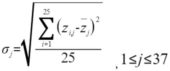
Wherein And representing the average value of j-th Zernike polynomial coefficients in a 25-horizontal group, and sorting the standard deviation in a descending order from large to small, namely selecting the features with m being 37, and screening the previous n Zernike polynomial orders. In the actual implementation process, a specific numerical value of n is selected according to the optimization quality of a mathematical model, namely whether a Zernike polynomial coefficient formed by the selected features and subjected to feature screening can relatively accurately reflect the variation trend of the surface shape error of the plastic optical lens when a plurality of first level values of the molding parameters of the injection molding machine are changed.
In a specific embodiment, n is 9, that is, the first 9 terms of the zernike polynomials with the variation ranges arranged from large to small are selected, that is, the 9 terms most sensitive to the forming parameters are selected as the selected characteristic values. Referring to fig. 3, the variation range of the numbers of the zernike polynomial coefficients can be seen through the vertical axis, the horizontal axis is the degree of the zernike polynomial coefficients (i.e. the features), and the features screened according to the fluctuation range, i.e. according to the standard deviation of the zernike polynomial coefficients of different degrees, are respectively the 4 th, 1 st, 9 th, 5 th, 16 th, 14 th, 25 th, 12 th and 23 th degree of the zernike polynomial coefficients.
And step S14, performing machine learning by using a plurality of first horizontal values corresponding to the molding parameters and the Zernike polynomial coefficients subjected to feature screening as training data to obtain a trained machine learning model.
In this embodiment, the obtaining of the machine learning model by machine learning is implemented by selecting an appropriate mathematical model:
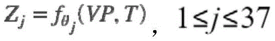
wherein Z isjRepresenting the j-th Zernike polynomial coefficient, θjRepresents and ZjCorresponding mathematical model parameters to be learned, such as regression coefficients and random error terms in a linear regression mathematical model, VP representing V-P switching pressure, T representing mold temperature, and computer training a machine learning model using the mathematical model to obtain θj。
In specific embodiments, the mathematical model may be selected from different mathematical models, such as linear regression, quadratic model, logistic regression, SVM, artificial neural network, and the like, according to different factors such as actual variation trend, accuracy requirement, calculation cost, and the like. In one embodiment, the mathematical model is selected as a binary linear regression mathematical model.
Specifically, the molding parameters of the injection molding machine as training data are mold temperature and V-P switching pressure, and a binary linear regression mathematical model is used for training. Respectively taking the mold temperature and the V-P switching pressure as independent variables x1、x2The coefficients of the Zernike polynomials are input as dependent variables f (x) into the following binary linear regression mathematical model for training:
f(x)=w1x1+w2x2+b
to obtain thetajTo obtain w corresponding to each Zernike polynomial coefficient1、w2And b, wherein w1、w2B is a random error term, thereby obtaining a mathematical model Zj:
Zj,1≤j≤37
Through carrying out machine learning with the Zernike polynomial coefficient through the characteristic screening as training data, the discrimination of machine learning model is better, and the effect more is close to the condition of actual production to guide production, improve the product yield.
Step S15, inputting a plurality of second level values corresponding to the molding parameters of the injection molding machine into the trained machine learning model as input data, and outputting a predicted zernike polynomial coefficient, where the second level values are used in a machine learning model application stage and are different from the first level values used in the machine learning model training stage.
In one embodiment, the molding parameters of the injection molding machine are still the mold temperature and the V-P switching pressure, and the mathematical model obtained in step S14 is:
f(x)=w1x1+w2x2+b
wherein each Zernike polynomial coefficient corresponds to w1、w2And b is known, in the machine learning model application stage, a plurality of second horizontal values corresponding to the molding parameters of the injection molding machine are used as input data to be input into the mathematical model, and the predicted Zernike polynomial coefficients can be output.
And step S16, the predicted Zernike polynomial coefficient is subjected to reduction processing to obtain a predicted surface shape error.
In this embodiment, in step S13, when the surface shape error is subjected to zernike polynomial fitting to obtain 37 zernike polynomial coefficients, in step S16, the reduction process is to reduce the 37 zernike polynomial coefficients to the predicted surface shape error corresponding to the surface shape data.
The invention takes the Zernike (Zernike) polynomial coefficient obtained by fitting the surface shape error as the object of machine learning, greatly simplifies the mathematical model, accelerates the training process and realizes the quick and simple acquisition of the surface shape error predicted by the plastic optical lens; in addition, the surface shape error of the plastic optical lens can be conveniently and simply predicted through the training of the machine learning model, and a reference basis is provided for optimizing the molding parameters of the injection molding machine for processing the plastic optical lens, so that the production guidance is realized, and the product yield is improved.
Further, after the step S16, the method for predicting the surface shape error of the plastic optical lens may include the step S17: judging whether the predicted surface shape error is in a first target range, if so, performing mass production on the plastic optical lens by using the second level value, and if not, returning to the step S15 to replace the second level value and performing the steps S15 and S16 again until the predicted surface shape error is in the first target range, and then performing the step S18: and mass-producing the plastic optical lens by adopting the second horizontal value. The first target range differs depending on the plastic optical lens.
Specifically, determining whether the predicted surface shape error is within a first target range includes adding the predicted surface shape error and preset surface shape data to obtain predicted surface shape data of the plastic optical lens, and generating a simulation diagram of the predicted surface shape of the plastic optical lens. Therefore, whether the design requirement is met or not can be determined by observing the shape and the peak-to-valley value (PV value) of the simulation diagram of the predicted surface shape intuitively, and whether the plastic optical lens is to be produced in mass production according to the molding parameters can be further determined.
In the present embodiment, the first target range is the PV value, the shape of the plastic optical lens may be various according to actual production needs, such as "M" shape and "V" shape, and the PV value has different ranges according to design requirements of plastic optical lenses with different shapes. For example, the first target range is 0.43 μm ≦ PV value ≦ 0.48 μm.
Please refer to fig. 4, wherein fig. 4a and fig. 4b respectively show that the second level is VP 700kg · F/cm2And T is a simulation diagram of the predicted surface shape at 130 ℃. As can be seen from fig. 4a, the shape of the predicted surface shape of the plastic optical lens is "M" shape, the X-axis and the Y-axis in fig. 4a represent the diameter (unit: mm) of the predicted plastic optical lens, and the Z-axis represents the height Δ Z (unit: mm) of the point taken by the plastic optical lens. The curve X-Direction in fig. 4b is a curve of the portion X > 0 when Y is 0 in fig. 4a, and the curve Y-Direction is a curve of the portion Y > 0 when X is 0 in fig. 4a, and as can be seen from fig. 4b, the peak-to-valley value PV is 0.46647 μm, the horizontal axis in the figure represents the number of sampling points, and the vertical axis represents the height Δ Z (unit: mm) of the predicted point taken by the plastic optical lens. FIG. 4c and FIG. 4d are each a schematic view ofThe second level is VP 850 kg-F/cm2The shape of the predicted profile of the plastic optical lens is "V" shape, and the peak-to-valley value PV is 0.44378 μm. The PV values of the plastic optical lens predicted according to the above two sets of molding conditions are both within a first target range, so the plastic optical lens can be mass-produced using the second level value.
Further, based on the above embodiment, another embodiment of the plastic optical lens surface shape error prediction method according to the present invention is provided, and after step S14, the prediction method may include step S100: checking the precision of the machine learning model, if the precision of the machine learning model is within a second target range, executing step S15, if the precision of the machine learning model is not within the second target range, returning to step S14, executing step S14 and step S100 again after adopting different types of machine learning models until the precision of the machine learning model is within the second target range, and continuing to execute steps S15-S18.
In one embodiment, the second target range represents a range of a coefficient of determination (R-square value) of a mathematical model used by the machine learning model during fitting, i.e., the R-square value is used to verify the accuracy of the machine learning model.
Specifically, the 4 th, 1 th, 9 th, 5 th, 16 th, 14 th, 25 th, 12 th and 23 th Zernike polynomial coefficients screened out through the characteristics are respectively subjected to simulation and demonstration of a linear regression model training result, when a predicted change trend graph and an actual change trend graph tend to be close to each other, the R-square value also approaches a second target range, and when the R-square value is in the second target range, the precision of the mathematical model meets the requirement.
For example, the second target range is 0.8 ≦ R2And the value is less than or equal to 1, and figure 5 is a schematic diagram of the result of training by adopting a linear regression model, wherein the selected item 4 is the item with the largest standard deviation of Zernike polynomial coefficients in the characteristic screening stage, the X axis represents the mold temperature, the Y axis represents the V-P switching pressure, and the Z axis represents the Zernike polynomial coefficients. Wherein the curved surface isAnd measuring a change trend graph, wherein the grid graph is a corresponding actual change trend graph. The R-square value at this time, R in FIG. 520.92445, within the second target range, when the accuracy of the machine learning model meets the requirement, the machine learning model may be entered into the model application phase, i.e., step 15.
In this embodiment, the mathematical model used in the machine learning model is replaced when the accuracy of the machine learning model is not within the second target range, and in a specific embodiment, when the accuracy of the machine learning model is not within the second target range, the linear regression model is replaced with the quadratic model and step S14 is executed again, that is, the mold temperature and the V-P switching pressure are respectively used as independent variables x1、x2The coefficients of the Zernike polynomials are input as dependent variables f (x) into the following quadratic model for training:
f(x)=w1x1 2+w2x2 2+w3x1x2+w4x1+w5x2+b
to obtain thetajTo obtain w corresponding to each Zernike polynomial coefficient1、w2、w3、w4、w5And b, wherein w1、w2、w3Is a coefficient of quadratic term, w4And w5Is a first order coefficient, b is a random error term, thereby obtaining a well-trained mathematical model Zj:
Zj,1≤j≤37
Please refer to fig. 6, which is a diagram illustrating the result of the training using the quadratic model, at this time, the R-square value, i.e., R in fig. 620.99758, indicating that the accuracy of the machine learning model is satisfactory within the second target range.
By checking the precision of the machine learning model, the machine learning model can be optimized, so that the final machine learning model has good accuracy.
It is understood that, when the accuracy of the machine learning model is within the second target range, the prediction method may include the step S101: performing experimental verification on the machine learning model, inputting a plurality of third horizontal values corresponding to molding parameters of the injection molding machine as input data into the machine learning model with the learned parameters being completed, outputting predicted Zernike polynomial coefficients of an experimental verification stage, reducing the predicted Zernike polynomial coefficients of the experimental verification stage to obtain predicted surface shape errors of the experimental verification stage, if the predicted surface shape errors of the experimental verification stage are within a third target range, continuing to execute the step S15, if the predicted surface shape errors of the experimental verification stage are not within the third target range, returning to the step S11, replacing the molding parameters and a plurality of first horizontal values corresponding to the molding parameters, re-executing the prediction method until the predicted surface shape errors of the experimental verification stage are within the third target range, the execution of the steps S15-S18 is resumed. Wherein the third target range is a range of subtracting the PV value of the actual surface shape of the plastic optical lens at the experimental verification stage from the PV value of the predicted surface shape of the plastic optical lens at the experimental verification stage, i.e., -0.1 μm or less of the PV value of the predicted surface shape of the experimental verification stage-0.1 μm or less of the PV value of the actual surface shape of the experimental verification stage.
The third level value is one or more groups of level values corresponding to the molding parameters in the experimental verification stage, and is different from the first level value in the machine learning model training stage and the second level value in the machine learning application stage. The third level value may be selected together with or after the first level value. The third level value is different from the first level value. For example, the training data is divided into a training set and a validation set before the machine learning model is built, and after the machine learning model is built by using the training set, experimental validation is performed by using the validation set.
Specifically, determining whether the predicted surface shape error of the experimental verification stage is within a third target range includes adding the predicted surface shape error of the experimental verification stage and preset surface shape data to obtain predicted surface shape data of the experimental verification stage, generating a simulated diagram of the predicted surface shape of the experimental verification stage of the plastic optical lens, thereby obtaining a shape and a peak-valley value (PV value) of the simulated diagram of the predicted surface shape of the experimental verification stage, and comparing the shape and the peak-valley value of the predicted surface shape of the experimental verification stage with a shape and a peak-valley value of an actually measured surface shape of the experimental verification stage to determine whether the predicted surface shape error of the experimental verification stage is within the third target range.
In this embodiment, the third target range is-0.1 μm or less of the PV value of the predicted profile at the experimental verification stage-0.1 μm or less of the PV value of the measured profile at the experimental verification stage. Referring to fig. 7, fig. 7a and 7b are simulation diagrams of the actual surface shapes of the plastic optical lens at the experimental verification stage, wherein the horizontal AXIS R-AXIS (mm) and the vertical AXIS Zd-AXIS (μ M) represent the actual measurement size at the experimental verification stage. Fig. 7a and 7b are simulation diagrams generated by actual measurement of the dimensions of the plastic optical lens after the plastic optical lens is processed by the injection molding machine at the experimental verification stage. For example, FIG. 7a shows that the PV value of the measured profile of the experimental verification stage is 0.307 μm, and if the PV value of the predicted profile of the experimental verification stage is-0.1 μm ≦ 0.307 μm ≦ 0.1 μm of the PV value of the predicted profile of the experimental verification stage +0.1 μm, the error of the predicted profile of the experimental verification stage is within the third target range, and the step S15 is continuously performed.
Through the experimental verification of the machine learning model, the prediction effect of the machine learning model can be confirmed, and the forming parameters required by the machine learning model and a plurality of corresponding first horizontal values of the forming parameters are convenient to adjust in time, so that the finally obtained machine learning model can perform good prediction on the surface shape error.
Please refer to fig. 8, which is a schematic structural diagram of an electronic device 20 according to an embodiment of the present disclosure. The electronic device 20 includes, but is not limited to, a memory 201, a processor 202, and a computer program 203 stored in the memory 201 and executable on the processor 202. The processor 202, when executing the computer program 203, implements the steps of the above-mentioned plastic optical lens surface shape error prediction method, such as the steps S11-S17 & S100-S101 shown in fig. 1.
Illustratively, the computer program 203 may be partitioned into one or more modules/units that are stored in the memory 201 and executed by the processor 202 to accomplish the present application. The one or more modules/units may be a series of computer program instruction segments capable of performing specific functions, the instruction segments describing the execution process of the computer program 203 in the electronic device 20.
It will be understood by those skilled in the art that the schematic diagram is merely an example of the electronic apparatus 20, does not constitute a limitation of the electronic apparatus 20, and may include more or less components than those shown, or combine some components, or different components, for example, the electronic apparatus 20 may further include an input-output device, a network access device, a bus, etc.
The Processor 202 may be a Central Processing Unit (CPU), other general purpose Processor, a Digital Signal Processor (DSP), an Application Specific Integrated Circuit (ASIC), a Field-Programmable Gate Array (FPGA) or other Programmable logic device, discrete Gate or transistor logic device, discrete hardware component, or the like. A general purpose processor may be a microprocessor or the processor 202 may be any conventional processor or the like, the processor 202 being the control center of the electronic device 20 and connecting the various parts of the entire electronic device 20 using various interfaces and lines.
The memory 201 may be used for storing the computer program 203 and/or the module/unit, and the processor 202 may implement various functions of the electronic device 20 by executing or executing the computer program and/or the module/unit stored in the memory 201 and calling data stored in the memory 201. The memory 201 may mainly include a storage program area and a storage data area, wherein the storage program area may store an operating system, an application program required by at least one function (such as a sound playing function, an image playing function, etc.), and the like; the stored data area may store data (such as audio data, a phonebook, etc.) created according to the use of the electronic device 20, and the like. In addition, the memory 201 may include volatile and non-volatile memory, such as a hard disk, a memory, a plug-in hard disk, a Smart Media Card (SMC), a Secure Digital (SD) Card, a Flash memory Card (Flash Card), at least one magnetic disk storage device, a Flash memory device, or other storage devices.
The integrated modules/units of the electronic device 20 may be stored in a computer-readable storage medium if they are implemented in the form of software functional units and sold or used as separate products. Based on such understanding, all or part of the flow in the method of the embodiments described above can be realized by a computer program, which can be stored in a computer-readable storage medium, and when the computer program is executed by a processor, the steps of the method embodiments described above can be realized. Wherein the computer program comprises computer program code, which may be in the form of source code, object code, an executable file or some intermediate form, etc. The computer-readable medium may include: any entity or device capable of carrying said computer program code, recording medium, U-disk, removable hard disk, magnetic disk, optical disk, computer Memory, Read-Only Memory (ROM), Random Access Memory (RAM).
According to the plastic optical lens surface shape error prediction method, the electronic device and the storage medium, the predicted surface shape error of the plastic optical lens before mass production is obtained by adopting the Zernike polynomial coefficient, the mapping relation between the coordinate data of the surface of the plastic optical lens and the molding parameters of the injection molding machine is simplified into the mapping relation between the Zernike polynomial coefficient and the molding parameters of the injection molding machine, and therefore the predicted surface shape error of the plastic optical lens can be quickly and simply obtained without complex mathematical relation calculation; in addition, the surface shape error of the plastic optical lens can be conveniently and simply predicted through the training of the machine learning model, and a reference basis is provided for optimizing the molding parameters of the injection molding machine for mass production processing of the plastic optical lens, so that the production guidance is realized, and the product yield is improved.
It will be evident to those skilled in the art that the invention is not limited to the details of the foregoing illustrative embodiments, and that the present invention may be embodied in other specific forms without departing from the spirit or essential attributes thereof. The present embodiments are therefore to be considered in all respects as illustrative and not restrictive, the scope of the invention being indicated by the appended claims rather than by the foregoing description, and all changes which come within the meaning and range of equivalency of the claims are therefore intended to be embraced therein. Any reference sign in a claim should not be construed as limiting the claim concerned. Furthermore, it is to be understood that the word "comprising" does not exclude other modules or steps, and the singular does not exclude the plural. Several modules or electronic devices recited in the electronic device claims may also be implemented by one and the same module or electronic device by means of software or hardware. The terms first, second, etc. are used to denote names, but not any particular order.
Finally, it should be noted that the above embodiments are only intended to illustrate the technical solutions of the present invention and not to limit the same, and although the present invention has been described in detail with reference to the preferred embodiments, it should be understood by those skilled in the art that modifications or equivalent substitutions may be made to the technical solutions of the present invention without departing from the spirit and scope of the technical solutions of the present invention.
Claims (10)
1. A method for predicting surface shape error of a plastic optical lens is characterized by comprising the following steps:
step S11, obtaining a molding parameter of the injection molding machine and a plurality of corresponding first horizontal values, and establishing an orthogonal table according to the molding parameter and the plurality of corresponding first horizontal values to obtain a plurality of molding conditions;
step S12, pre-producing the plastic optical lens according to the forming conditions, obtaining the actually measured surface shape data of the plastic optical lens, and calculating the difference between the preset surface shape data of the plastic optical lens and the actually measured surface shape data to obtain a plurality of groups of surface shape errors of the plastic optical lens;
step S13, the plurality of groups of surface shape errors are respectively quantized into a plurality of Zernike polynomial coefficients, and feature screening is carried out on the plurality of Zernike polynomial coefficients;
step S14, performing machine learning by using a plurality of first horizontal values corresponding to the molding parameters and the Zernike polynomial coefficients subjected to feature screening as training data to obtain a machine learning model; the machine learning model is obtained by adopting a linear regression mathematical model or a quadratic model for training;
step S15, inputting a plurality of second level values corresponding to the molding parameters of the injection molding machine into the machine learning model as input data, and outputting predicted zernike polynomial coefficients, where the second level values are used in the machine learning model application stage and are different from the first level values used in the machine learning model training stage;
and step S16, the predicted Zernike polynomial coefficient is subjected to reduction processing to obtain a predicted surface shape error.
2. The method of predicting surface shape error of plastic optical lens according to claim 1, wherein the molding parameters include mold temperature and V-P switching pressure.
3. The method for predicting surface shape error of plastic optical lens according to claim 2, wherein the mold temperature is set to 5 first level values, the V-P switching pressure is set to 5 first level values, the 5 first level values of the mold temperature are provided as columns of the orthogonal table, the 5 first level values of the V-P switching pressure are provided as columns of the orthogonal table, the orthogonal table with 25 composition conditions is established, and the 5 first level values of the mold temperature are respectively set to 5 first level values: 124 ℃, 127 ℃, 130 ℃, 133 ℃ and 137 ℃, wherein the 5 first level values of the V-P switching pressure are respectively as follows: 600 kg. F/cm2、700kg·F/cm2、800kg·F/cm2、900kg·F/cm2And 1000 kg. F/cm2。
4. The method of predicting surface shape errors of a plastic optical lens as claimed in claim 1, wherein the step of quantizing the sets of surface shape errors into a plurality of zernike polynomial coefficients, respectively, comprises: and in each group of quantization processes, the Zernike polynomials are used as basis functions, and the plurality of groups of surface shape errors are fitted to obtain the plurality of Zernike polynomial coefficients.
5. The method for predicting the surface shape error of the plastic optical lens as claimed in claim 1, wherein the feature screening comprises: and calculating the standard deviation of the plurality of Zernike polynomial coefficients, sorting the standard deviation in a descending order, and screening a plurality of Zernike polynomial orders of which the standard deviations are arranged from large to small and are close to the front.
6. The plastic optical lens surface shape error prediction method of claim 1, wherein after the step S16, the prediction method comprises the steps of S17: judging whether the predicted surface shape error is in a first target range, if the predicted surface shape error is in the first target range, mass-producing the plastic optical lens by using the second level value, if the predicted surface shape error is not in the first target range, returning to step S15 to replace the second level value and re-executing the steps S15 and S16 until the predicted surface shape error is in the first target range, and then executing step S18: mass-producing the plastic optical lens by using the second horizontal value; wherein the first target range is a range of a peak-to-valley PV value of the predicted profile of the plastic optical lens, that is, the PV value of the predicted profile is less than or equal to 0.43 μm and less than or equal to 0.48 μm.
7. The plastic optical lens surface shape error prediction method according to claim 1, wherein after step S14, the prediction method comprises step S100: checking the precision of the machine learning model, if the precision of the machine learning model is within a second target range, executing step S15, if the precision of the machine learning model is not within the second target range, returning to step S14, and executing step S14 and step S100 again after adopting different types of machine learning models until the precision of the machine learning model is within the second target range; the second target range is the range of the determination coefficient R-square value of the mathematical model adopted by the machine learning model in the fitting process, namely the R-square value is more than or equal to 0.8 and less than or equal to 1.
8. The plastic optical lens surface shape error prediction method according to claim 7, wherein when the accuracy of the machine learning model is within the second target range, the prediction method comprises the step S101 of: performing experimental verification on the machine learning model, inputting a plurality of third horizontal values corresponding to molding parameters of the injection molding machine into the machine learning model as input data, outputting predicted Zernike polynomial coefficients of an experimental verification stage, reducing the predicted Zernike polynomial coefficients of the experimental verification stage to obtain predicted surface shape errors of the experimental verification stage, if the predicted surface shape errors of the experimental verification stage are within a third target range, continuing to execute the step S15, if the predicted surface shape errors of the experimental verification stage are not within the third target range, returning to the step S11, replacing the molding parameters and a plurality of first horizontal values corresponding to the molding parameters, and re-executing the prediction method until the predicted surface shape errors of the experimental verification stage are within the third target range; wherein the third target range is a range of subtracting the PV value of the actual surface shape of the plastic optical lens at the experimental verification stage from the PV value of the predicted surface shape of the plastic optical lens at the experimental verification stage, i.e., -0.1 μm or less of the PV value of the predicted surface shape of the experimental verification stage-0.1 μm or less of the PV value of the actual surface shape of the experimental verification stage.
9. An electronic device, comprising:
a processor; and
a memory having stored therein a plurality of program modules that are loaded by the processor and execute the plastic optical lens surface shape error prediction method according to any one of claims 1 to 8.
10. A computer readable storage medium having stored thereon at least one computer instruction, wherein the instruction is loaded by a processor and executes the method for predicting plastic optical lens surface shape error as claimed in any one of claims 1 to 8.
Priority Applications (1)
| Application Number | Priority Date | Filing Date | Title |
|---|---|---|---|
| CN202110485869.XA CN113283162B (en) | 2021-04-30 | 2021-04-30 | Plastic optical lens surface shape error prediction method, electronic device and storage medium |
Applications Claiming Priority (1)
| Application Number | Priority Date | Filing Date | Title |
|---|---|---|---|
| CN202110485869.XA CN113283162B (en) | 2021-04-30 | 2021-04-30 | Plastic optical lens surface shape error prediction method, electronic device and storage medium |
Publications (2)
| Publication Number | Publication Date |
|---|---|
| CN113283162A true CN113283162A (en) | 2021-08-20 |
| CN113283162B CN113283162B (en) | 2022-10-28 |
Family
ID=77277836
Family Applications (1)
| Application Number | Title | Priority Date | Filing Date |
|---|---|---|---|
| CN202110485869.XA Active CN113283162B (en) | 2021-04-30 | 2021-04-30 | Plastic optical lens surface shape error prediction method, electronic device and storage medium |
Country Status (1)
| Country | Link |
|---|---|
| CN (1) | CN113283162B (en) |
Cited By (3)
| Publication number | Priority date | Publication date | Assignee | Title |
|---|---|---|---|---|
| CN114161240A (en) * | 2021-12-15 | 2022-03-11 | 清华大学 | Grinding surface shape prediction method, grinding system and terminal equipment |
| CN116305667A (en) * | 2023-05-18 | 2023-06-23 | 贵州大学 | Surface error control method for centrally symmetrical convex surface of large diameter thin plate parts |
| CN118650834A (en) * | 2024-08-09 | 2024-09-17 | 广州市简达实业有限公司 | An injection mold online temperature monitoring and early warning method and system |
Citations (12)
| Publication number | Priority date | Publication date | Assignee | Title |
|---|---|---|---|---|
| TW200942394A (en) * | 2008-04-03 | 2009-10-16 | Nat Applied Res Laboratories | Compensation method for optics mold |
| US20110157545A1 (en) * | 2005-11-09 | 2011-06-30 | Applegate Raymond A | Method for Designing and Manufacturing Custom Optics |
| US20130297015A1 (en) * | 2012-05-07 | 2013-11-07 | Boston Foundation For Sight | Customized wavefront-guided methods, systems, and devices to correct higher-order aberrations |
| US20150120216A1 (en) * | 2013-10-29 | 2015-04-30 | Kla-Tencor Corporation | Process-Induced Distortion Prediction and Feedforward and Feedback Correction of Overlay Errors |
| CN106873152A (en) * | 2017-01-11 | 2017-06-20 | 浙江大学 | A kind of high speed aberration correcting method based on machine learning |
| CN108089322A (en) * | 2018-01-10 | 2018-05-29 | 清华大学深圳研究生院 | Distorting lens iteration control method and system based on multiple linear regression |
| CN109642876A (en) * | 2016-09-02 | 2019-04-16 | Asml荷兰有限公司 | For monitoring the method and system of process equipment |
| CN110188321A (en) * | 2019-05-22 | 2019-08-30 | 中国科学院光电技术研究所 | A primary and secondary mirror calibration method based on neural network algorithm |
| CN110705040A (en) * | 2019-09-11 | 2020-01-17 | 中国科学院光电技术研究所 | Method for solving primary and secondary mirror offset error quantity based on Zernike polynomial coefficient and least square method |
| CN110715619A (en) * | 2019-11-22 | 2020-01-21 | 北京理工大学 | Measurement method of optical free-form surface error based on adaptive non-zero interferometry |
| CN111008945A (en) * | 2019-12-31 | 2020-04-14 | 哈工大机器人(中山)无人装备与人工智能研究院 | Multi-image-quality-parameter self-adaptive aberration correction method and device based on machine learning |
| CN111209689A (en) * | 2020-02-14 | 2020-05-29 | 北京理工大学 | Non-zero interference aspheric surface measurement return error removal method and device |
-
2021
- 2021-04-30 CN CN202110485869.XA patent/CN113283162B/en active Active
Patent Citations (12)
| Publication number | Priority date | Publication date | Assignee | Title |
|---|---|---|---|---|
| US20110157545A1 (en) * | 2005-11-09 | 2011-06-30 | Applegate Raymond A | Method for Designing and Manufacturing Custom Optics |
| TW200942394A (en) * | 2008-04-03 | 2009-10-16 | Nat Applied Res Laboratories | Compensation method for optics mold |
| US20130297015A1 (en) * | 2012-05-07 | 2013-11-07 | Boston Foundation For Sight | Customized wavefront-guided methods, systems, and devices to correct higher-order aberrations |
| US20150120216A1 (en) * | 2013-10-29 | 2015-04-30 | Kla-Tencor Corporation | Process-Induced Distortion Prediction and Feedforward and Feedback Correction of Overlay Errors |
| CN109642876A (en) * | 2016-09-02 | 2019-04-16 | Asml荷兰有限公司 | For monitoring the method and system of process equipment |
| CN106873152A (en) * | 2017-01-11 | 2017-06-20 | 浙江大学 | A kind of high speed aberration correcting method based on machine learning |
| CN108089322A (en) * | 2018-01-10 | 2018-05-29 | 清华大学深圳研究生院 | Distorting lens iteration control method and system based on multiple linear regression |
| CN110188321A (en) * | 2019-05-22 | 2019-08-30 | 中国科学院光电技术研究所 | A primary and secondary mirror calibration method based on neural network algorithm |
| CN110705040A (en) * | 2019-09-11 | 2020-01-17 | 中国科学院光电技术研究所 | Method for solving primary and secondary mirror offset error quantity based on Zernike polynomial coefficient and least square method |
| CN110715619A (en) * | 2019-11-22 | 2020-01-21 | 北京理工大学 | Measurement method of optical free-form surface error based on adaptive non-zero interferometry |
| CN111008945A (en) * | 2019-12-31 | 2020-04-14 | 哈工大机器人(中山)无人装备与人工智能研究院 | Multi-image-quality-parameter self-adaptive aberration correction method and device based on machine learning |
| CN111209689A (en) * | 2020-02-14 | 2020-05-29 | 北京理工大学 | Non-zero interference aspheric surface measurement return error removal method and device |
Non-Patent Citations (4)
| Title |
|---|
| DIEGO RODRÍGUEZ IBAÑEZ 等: "Robust fitting of Zernike polynomials to noisy point clouds defined over connected domains of arbitrary shape", 《OPTICS EXPRESS》 * |
| RADHIKA RAMPAT 等: "Using Artifcial Intelligence and Novel Polynomials to Predict Subjective Refraction", 《SCIENTIFIC REPORTS》 * |
| 王毅 等: "基于泽尼克多项式系数的大相对孔径表面超精密车削误差的补偿方法", 《红外与激光工程》 * |
| 高洪涛 等: "评价任意面型微光学元件制作误差的方法", 《微细加工技术》 * |
Cited By (4)
| Publication number | Priority date | Publication date | Assignee | Title |
|---|---|---|---|---|
| CN114161240A (en) * | 2021-12-15 | 2022-03-11 | 清华大学 | Grinding surface shape prediction method, grinding system and terminal equipment |
| CN116305667A (en) * | 2023-05-18 | 2023-06-23 | 贵州大学 | Surface error control method for centrally symmetrical convex surface of large diameter thin plate parts |
| CN116305667B (en) * | 2023-05-18 | 2023-07-28 | 贵州大学 | Surface shape error control method for central symmetrical convex surface shape of large-diameter sheet part |
| CN118650834A (en) * | 2024-08-09 | 2024-09-17 | 广州市简达实业有限公司 | An injection mold online temperature monitoring and early warning method and system |
Also Published As
| Publication number | Publication date |
|---|---|
| CN113283162B (en) | 2022-10-28 |
Similar Documents
| Publication | Publication Date | Title |
|---|---|---|
| CN113283162B (en) | Plastic optical lens surface shape error prediction method, electronic device and storage medium | |
| Zhou et al. | Single and multi objective optimization for injection molding using numerical simulation with surrogate models and genetic algorithms | |
| US11182519B2 (en) | Optimization method and module thereof based on feature extraction and machine learning | |
| CN112069610B (en) | Injection molding process parameter optimization method for transparent complex multi-cavity plastic part | |
| CN118862371B (en) | Deformation prediction method and system for injection molded parts of automobile | |
| CN110704424B (en) | Sorting method and device applied to database and related equipment | |
| CN115830385A (en) | Image detection method, device, electronic device, and computer-readable storage medium | |
| EP4129621B1 (en) | Apparatus, method, and program | |
| CN114239190A (en) | Technological parameter optimization method and device for injection molding of plastic workpiece | |
| CN117666471A (en) | Micro-line segment global smoothing method and system based on improved particle swarm genetic algorithm | |
| García-Martínez et al. | Toward data-driven research: preliminary study to predict surface roughness in material extrusion using previously published data with machine learning | |
| TWI783427B (en) | Apparatus, method and program for supporting resin molding | |
| CN114274457A (en) | Kriging-GA-based structural parameter decision method for injection mold pouring system | |
| CN114662232B (en) | A method for analyzing the forming quality of hot stamping parts with complex shapes | |
| CN118133637A (en) | A real-time simulation and mapping method of clamping stress field based on RBF model | |
| CN115816717B (en) | Manufacturing method of lightweight injection mold, lightweight injection mold and injection product | |
| Zafošnik et al. | Modelling of an analytical equation for predicting maximum stress in an injections moulded undercut geometry during ejection | |
| CN118607288A (en) | A dynamic modeling prediction and online process optimization method for spinning forming of curved parts | |
| CN116776958A (en) | Model parameter updating method and device for neural network model | |
| CN117392659A (en) | A vehicle license plate positioning method based on parameter-free attention mechanism optimization | |
| CN114491703A (en) | Method and device for acquiring bill of material (BOM) information, electronic equipment and medium | |
| CN112052514B (en) | Performance analysis method and system for automotive interior structures | |
| Ding et al. | Quality monitoring of injection molding based on TSO-SVM and MOSSA. | |
| Zhang | Detection of the Additive Manufacturing In-Process Failures via Deep Learning | |
| CN116186806A (en) | An intelligent analog-driven pre-processing system, electronic equipment, and storage medium for sheet metal forming simulation |
Legal Events
| Date | Code | Title | Description |
|---|---|---|---|
| PB01 | Publication | ||
| PB01 | Publication | ||
| SE01 | Entry into force of request for substantive examination | ||
| SE01 | Entry into force of request for substantive examination | ||
| GR01 | Patent grant | ||
| GR01 | Patent grant |