CN113275044B - Detection chip, use method thereof and detection device - Google Patents
Detection chip, use method thereof and detection device Download PDFInfo
- Publication number
- CN113275044B CN113275044B CN202010104016.2A CN202010104016A CN113275044B CN 113275044 B CN113275044 B CN 113275044B CN 202010104016 A CN202010104016 A CN 202010104016A CN 113275044 B CN113275044 B CN 113275044B
- Authority
- CN
- China
- Prior art keywords
- membrane valve
- membrane
- detection
- chip
- detection chip
- Prior art date
- Legal status (The legal status is an assumption and is not a legal conclusion. Google has not performed a legal analysis and makes no representation as to the accuracy of the status listed.)
- Active
Links
Images


Classifications
-
- B—PERFORMING OPERATIONS; TRANSPORTING
- B01—PHYSICAL OR CHEMICAL PROCESSES OR APPARATUS IN GENERAL
- B01L—CHEMICAL OR PHYSICAL LABORATORY APPARATUS FOR GENERAL USE
- B01L3/00—Containers or dishes for laboratory use, e.g. laboratory glassware; Droppers
- B01L3/50—Containers for the purpose of retaining a material to be analysed, e.g. test tubes
- B01L3/502—Containers for the purpose of retaining a material to be analysed, e.g. test tubes with fluid transport, e.g. in multi-compartment structures
- B01L3/5027—Containers for the purpose of retaining a material to be analysed, e.g. test tubes with fluid transport, e.g. in multi-compartment structures by integrated microfluidic structures, i.e. dimensions of channels and chambers are such that surface tension forces are important, e.g. lab-on-a-chip
- B01L3/502738—Containers for the purpose of retaining a material to be analysed, e.g. test tubes with fluid transport, e.g. in multi-compartment structures by integrated microfluidic structures, i.e. dimensions of channels and chambers are such that surface tension forces are important, e.g. lab-on-a-chip characterised by integrated valves
-
- B—PERFORMING OPERATIONS; TRANSPORTING
- B01—PHYSICAL OR CHEMICAL PROCESSES OR APPARATUS IN GENERAL
- B01L—CHEMICAL OR PHYSICAL LABORATORY APPARATUS FOR GENERAL USE
- B01L3/00—Containers or dishes for laboratory use, e.g. laboratory glassware; Droppers
- B01L3/50—Containers for the purpose of retaining a material to be analysed, e.g. test tubes
- B01L3/502—Containers for the purpose of retaining a material to be analysed, e.g. test tubes with fluid transport, e.g. in multi-compartment structures
- B01L3/5027—Containers for the purpose of retaining a material to be analysed, e.g. test tubes with fluid transport, e.g. in multi-compartment structures by integrated microfluidic structures, i.e. dimensions of channels and chambers are such that surface tension forces are important, e.g. lab-on-a-chip
- B01L3/50273—Containers for the purpose of retaining a material to be analysed, e.g. test tubes with fluid transport, e.g. in multi-compartment structures by integrated microfluidic structures, i.e. dimensions of channels and chambers are such that surface tension forces are important, e.g. lab-on-a-chip characterised by the means or forces applied to move the fluids
-
- B—PERFORMING OPERATIONS; TRANSPORTING
- B01—PHYSICAL OR CHEMICAL PROCESSES OR APPARATUS IN GENERAL
- B01L—CHEMICAL OR PHYSICAL LABORATORY APPARATUS FOR GENERAL USE
- B01L3/00—Containers or dishes for laboratory use, e.g. laboratory glassware; Droppers
- B01L3/50—Containers for the purpose of retaining a material to be analysed, e.g. test tubes
- B01L3/502—Containers for the purpose of retaining a material to be analysed, e.g. test tubes with fluid transport, e.g. in multi-compartment structures
- B01L3/5027—Containers for the purpose of retaining a material to be analysed, e.g. test tubes with fluid transport, e.g. in multi-compartment structures by integrated microfluidic structures, i.e. dimensions of channels and chambers are such that surface tension forces are important, e.g. lab-on-a-chip
- B01L3/502753—Containers for the purpose of retaining a material to be analysed, e.g. test tubes with fluid transport, e.g. in multi-compartment structures by integrated microfluidic structures, i.e. dimensions of channels and chambers are such that surface tension forces are important, e.g. lab-on-a-chip characterised by bulk separation arrangements on lab-on-a-chip devices, e.g. for filtration or centrifugation
-
- B—PERFORMING OPERATIONS; TRANSPORTING
- B01—PHYSICAL OR CHEMICAL PROCESSES OR APPARATUS IN GENERAL
- B01L—CHEMICAL OR PHYSICAL LABORATORY APPARATUS FOR GENERAL USE
- B01L3/00—Containers or dishes for laboratory use, e.g. laboratory glassware; Droppers
- B01L3/56—Labware specially adapted for transferring fluids
- B01L3/567—Valves, taps or stop-cocks
-
- B—PERFORMING OPERATIONS; TRANSPORTING
- B01—PHYSICAL OR CHEMICAL PROCESSES OR APPARATUS IN GENERAL
- B01L—CHEMICAL OR PHYSICAL LABORATORY APPARATUS FOR GENERAL USE
- B01L2200/00—Solutions for specific problems relating to chemical or physical laboratory apparatus
- B01L2200/06—Fluid handling related problems
- B01L2200/0647—Handling flowable solids, e.g. microscopic beads, cells, particles
- B01L2200/0652—Sorting or classification of particles or molecules
-
- B—PERFORMING OPERATIONS; TRANSPORTING
- B01—PHYSICAL OR CHEMICAL PROCESSES OR APPARATUS IN GENERAL
- B01L—CHEMICAL OR PHYSICAL LABORATORY APPARATUS FOR GENERAL USE
- B01L2200/00—Solutions for specific problems relating to chemical or physical laboratory apparatus
- B01L2200/06—Fluid handling related problems
- B01L2200/0647—Handling flowable solids, e.g. microscopic beads, cells, particles
- B01L2200/0668—Trapping microscopic beads
-
- B—PERFORMING OPERATIONS; TRANSPORTING
- B01—PHYSICAL OR CHEMICAL PROCESSES OR APPARATUS IN GENERAL
- B01L—CHEMICAL OR PHYSICAL LABORATORY APPARATUS FOR GENERAL USE
- B01L2200/00—Solutions for specific problems relating to chemical or physical laboratory apparatus
- B01L2200/06—Fluid handling related problems
- B01L2200/0689—Sealing
-
- B—PERFORMING OPERATIONS; TRANSPORTING
- B01—PHYSICAL OR CHEMICAL PROCESSES OR APPARATUS IN GENERAL
- B01L—CHEMICAL OR PHYSICAL LABORATORY APPARATUS FOR GENERAL USE
- B01L2200/00—Solutions for specific problems relating to chemical or physical laboratory apparatus
- B01L2200/10—Integrating sample preparation and analysis in single entity, e.g. lab-on-a-chip concept
-
- B—PERFORMING OPERATIONS; TRANSPORTING
- B01—PHYSICAL OR CHEMICAL PROCESSES OR APPARATUS IN GENERAL
- B01L—CHEMICAL OR PHYSICAL LABORATORY APPARATUS FOR GENERAL USE
- B01L2300/00—Additional constructional details
- B01L2300/04—Closures and closing means
- B01L2300/046—Function or devices integrated in the closure
- B01L2300/049—Valves integrated in closure
-
- B—PERFORMING OPERATIONS; TRANSPORTING
- B01—PHYSICAL OR CHEMICAL PROCESSES OR APPARATUS IN GENERAL
- B01L—CHEMICAL OR PHYSICAL LABORATORY APPARATUS FOR GENERAL USE
- B01L2300/00—Additional constructional details
- B01L2300/08—Geometry, shape and general structure
- B01L2300/0809—Geometry, shape and general structure rectangular shaped
- B01L2300/0816—Cards, e.g. flat sample carriers usually with flow in two horizontal directions
-
- B—PERFORMING OPERATIONS; TRANSPORTING
- B01—PHYSICAL OR CHEMICAL PROCESSES OR APPARATUS IN GENERAL
- B01L—CHEMICAL OR PHYSICAL LABORATORY APPARATUS FOR GENERAL USE
- B01L2300/00—Additional constructional details
- B01L2300/08—Geometry, shape and general structure
- B01L2300/0809—Geometry, shape and general structure rectangular shaped
- B01L2300/0819—Microarrays; Biochips
-
- B—PERFORMING OPERATIONS; TRANSPORTING
- B01—PHYSICAL OR CHEMICAL PROCESSES OR APPARATUS IN GENERAL
- B01L—CHEMICAL OR PHYSICAL LABORATORY APPARATUS FOR GENERAL USE
- B01L2300/00—Additional constructional details
- B01L2300/08—Geometry, shape and general structure
- B01L2300/0887—Laminated structure
-
- B—PERFORMING OPERATIONS; TRANSPORTING
- B01—PHYSICAL OR CHEMICAL PROCESSES OR APPARATUS IN GENERAL
- B01L—CHEMICAL OR PHYSICAL LABORATORY APPARATUS FOR GENERAL USE
- B01L2300/00—Additional constructional details
- B01L2300/12—Specific details about materials
- B01L2300/123—Flexible; Elastomeric
-
- B—PERFORMING OPERATIONS; TRANSPORTING
- B01—PHYSICAL OR CHEMICAL PROCESSES OR APPARATUS IN GENERAL
- B01L—CHEMICAL OR PHYSICAL LABORATORY APPARATUS FOR GENERAL USE
- B01L2400/00—Moving or stopping fluids
- B01L2400/04—Moving fluids with specific forces or mechanical means
- B01L2400/0403—Moving fluids with specific forces or mechanical means specific forces
- B01L2400/043—Moving fluids with specific forces or mechanical means specific forces magnetic forces
-
- B—PERFORMING OPERATIONS; TRANSPORTING
- B01—PHYSICAL OR CHEMICAL PROCESSES OR APPARATUS IN GENERAL
- B01L—CHEMICAL OR PHYSICAL LABORATORY APPARATUS FOR GENERAL USE
- B01L2400/00—Moving or stopping fluids
- B01L2400/04—Moving fluids with specific forces or mechanical means
- B01L2400/0475—Moving fluids with specific forces or mechanical means specific mechanical means and fluid pressure
- B01L2400/0481—Moving fluids with specific forces or mechanical means specific mechanical means and fluid pressure squeezing of channels or chambers
-
- B—PERFORMING OPERATIONS; TRANSPORTING
- B01—PHYSICAL OR CHEMICAL PROCESSES OR APPARATUS IN GENERAL
- B01L—CHEMICAL OR PHYSICAL LABORATORY APPARATUS FOR GENERAL USE
- B01L2400/00—Moving or stopping fluids
- B01L2400/04—Moving fluids with specific forces or mechanical means
- B01L2400/0475—Moving fluids with specific forces or mechanical means specific mechanical means and fluid pressure
- B01L2400/0487—Moving fluids with specific forces or mechanical means specific mechanical means and fluid pressure fluid pressure, pneumatics
-
- B—PERFORMING OPERATIONS; TRANSPORTING
- B01—PHYSICAL OR CHEMICAL PROCESSES OR APPARATUS IN GENERAL
- B01L—CHEMICAL OR PHYSICAL LABORATORY APPARATUS FOR GENERAL USE
- B01L2400/00—Moving or stopping fluids
- B01L2400/06—Valves, specific forms thereof
- B01L2400/0633—Valves, specific forms thereof with moving parts
- B01L2400/0638—Valves, specific forms thereof with moving parts membrane valves, flap valves
-
- B—PERFORMING OPERATIONS; TRANSPORTING
- B01—PHYSICAL OR CHEMICAL PROCESSES OR APPARATUS IN GENERAL
- B01L—CHEMICAL OR PHYSICAL LABORATORY APPARATUS FOR GENERAL USE
- B01L2400/00—Moving or stopping fluids
- B01L2400/06—Valves, specific forms thereof
- B01L2400/0633—Valves, specific forms thereof with moving parts
- B01L2400/0655—Valves, specific forms thereof with moving parts pinch valves
Landscapes
- Chemical & Material Sciences (AREA)
- Health & Medical Sciences (AREA)
- Clinical Laboratory Science (AREA)
- Chemical Kinetics & Catalysis (AREA)
- Dispersion Chemistry (AREA)
- Analytical Chemistry (AREA)
- General Health & Medical Sciences (AREA)
- Hematology (AREA)
- Life Sciences & Earth Sciences (AREA)
- Molecular Biology (AREA)
- Apparatus Associated With Microorganisms And Enzymes (AREA)
- Automatic Analysis And Handling Materials Therefor (AREA)
Abstract
一种检测芯片及其使用方法、检测装置,该检测芯片包括层叠设置的芯片基板和第一密封膜。芯片基板包括第一表面,第一密封膜覆盖芯片基板的第一表面。芯片基板还包括位于第一表面的流体通道,流体通道包括多个膜阀部。膜阀部配置为允许第一密封膜覆盖膜阀部的部分贴近和分离,从而可对应地关闭和开启流体通道。该检测芯片结构简单,可以定量输送试剂。
A detection chip, a method of using the same, and a detection device, the detection chip includes a chip substrate and a first sealing film arranged in layers. The chip substrate includes a first surface, and the first sealing film covers the first surface of the chip substrate. The chip substrate also includes a fluid channel on the first surface, the fluid channel including a plurality of membrane valve portions. The membrane valve portion is configured to allow the portion of the first sealing membrane covering the membrane valve portion to be approached and separated so that the fluid passage can be closed and opened accordingly. The detection chip has a simple structure and can quantitatively deliver reagents.
Description
技术领域technical field
本公开的实施例涉及一种检测芯片及其使用方法、检测装置。Embodiments of the present disclosure relate to a detection chip, a method for using the same, and a detection device.
背景技术Background technique
微流控芯片技术把生物、化学和医学等领域中所涉及的样品制备、反应、分离、检测等基本操作单元集成到一块具有微米尺度微通道的芯片上,自动完成反应和分析的全过程。该过程所使用的芯片叫做微流控芯片,也可称为芯片实验室(Lab-on-a-chip)。微流控芯片技术具有样本用量少,分析速度快,便于制成便携式仪器,适用于即时、现场分析等优点,已广泛应用于生物、化学和医学等诸多领域。Microfluidic chip technology integrates basic operation units such as sample preparation, reaction, separation, detection, etc. involved in the fields of biology, chemistry, and medicine into a chip with micron-scale microchannels, and automatically completes the entire process of reaction and analysis. The chip used in this process is called a microfluidic chip, also known as a Lab-on-a-chip. Microfluidic chip technology has the advantages of less sample consumption, fast analysis speed, easy to make into a portable instrument, suitable for instant and on-site analysis, etc., and has been widely used in many fields such as biology, chemistry and medicine.
发明内容SUMMARY OF THE INVENTION
本公开至少一个实施例提供一种检测芯片,包括层叠设置的芯片基板和第一密封膜,其中,所述芯片基板包括第一表面,所述第一密封膜覆盖所述芯片基板的所述第一表面,所述芯片基板还包括位于所述第一表面的流体通道,所述流体通道包括多个膜阀部,所述膜阀部配置为允许所述第一密封膜覆盖所述膜阀部的部分贴近和分离,从而可对应地关闭和开启所述流体通道。At least one embodiment of the present disclosure provides a detection chip, which includes a chip substrate and a first sealing film that are stacked in layers, wherein the chip substrate includes a first surface, and the first sealing film covers the first sealing film of the chip substrate. a surface, the chip substrate further includes a fluid channel on the first surface, the fluid channel including a plurality of membrane valve portions, the membrane valve portions configured to allow the first sealing membrane to cover the membrane valve portion The parts are close to and apart, so that the fluid channels can be closed and opened correspondingly.
例如,本公开一实施例提供的检测芯片还包括膜阀密封板,其中,所述膜阀密封板设置在所述第一密封膜远离所述芯片基板的一侧且包括多个凸起结构,所述多个凸起结构与所述多个膜阀部一一对应,且在所述多个凸起结构与所述多个膜阀部分别彼此接触的情形,关闭所述流体通道。For example, the detection chip provided by an embodiment of the present disclosure further includes a membrane valve sealing plate, wherein the membrane valve sealing plate is disposed on a side of the first sealing film away from the chip substrate and includes a plurality of protruding structures, The plurality of protruding structures correspond to the plurality of membrane valve portions one-to-one, and when the plurality of protruding structures and the plurality of membrane valve portions are in contact with each other, respectively, the fluid channel is closed.
例如,在本公开一实施例提供的检测芯片中,所述第一密封膜为弹性膜。For example, in the detection chip provided by an embodiment of the present disclosure, the first sealing film is an elastic film.
例如,在本公开一实施例提供的检测芯片中,所述芯片基板还包括至少一个储液池,所述至少一个储液池与所述流体通道连通,所述多个膜阀部中至少一个被配置为关闭和开启所述流体通道与所述至少一个储液池相连通的部分。For example, in the detection chip provided by an embodiment of the present disclosure, the chip substrate further includes at least one liquid storage tank, the at least one liquid storage tank communicates with the fluid channel, and at least one of the plurality of membrane valve parts A portion of the fluid channel in communication with the at least one reservoir is configured to close and open.
例如,在本公开一实施例提供的检测芯片中,所述流体通道还包括提取区和多条第一支路,所述至少一个储液池包括多个储液池,所述多条第一支路与所述多个储液池一一对应连通,所述多条第一支路均与所述提取区连通,所述多个膜阀部包括分别位于所述多条第一支路上的多个第一膜阀部,以控制所述多条第一支路开启或关闭。For example, in the detection chip provided by an embodiment of the present disclosure, the fluid channel further includes an extraction area and a plurality of first branches, the at least one liquid storage tank includes a plurality of liquid storage tanks, and the plurality of first branches The branches are in one-to-one correspondence with the plurality of liquid storage tanks, the plurality of first branches are all communicated with the extraction area, and the plurality of membrane valve parts include a plurality of first branches respectively located on the plurality of first branches. a plurality of first membrane valve parts to control the opening or closing of the plurality of first branches.
例如,在本公开一实施例提供的检测芯片中,所述流体通道还包括反应区和多条第二支路,所述反应区通过所述多条第二支路分别与所述提取区以及所述多个储液池中的至少一个连通,所述多个膜阀部还包括分别位于所述多条第二支路上的多个第二膜阀部,以控制所述多条第二支路开启或关闭。For example, in the detection chip provided by an embodiment of the present disclosure, the fluid channel further includes a reaction area and a plurality of second branches, and the reaction area is respectively connected to the extraction area and the extraction area through the plurality of second branches. At least one of the plurality of liquid storage tanks is in communication, and the plurality of membrane valve parts further include a plurality of second membrane valve parts respectively located on the plurality of second branches, so as to control the plurality of second branches road on or off.
例如,在本公开一实施例提供的检测芯片中,所述反应区包括多孔结构,所述多孔结构包括多个储液孔,所述多个储液孔配置为储存相同或不同的扩增引物。For example, in the detection chip provided by an embodiment of the present disclosure, the reaction area includes a porous structure, and the porous structure includes a plurality of liquid storage holes, and the plurality of liquid storage holes are configured to store the same or different amplification primers .
例如,在本公开一实施例提供的检测芯片中,所述多个储液池包括第一储液池、第二储液池、第三储液池、第四储液池和第五储液池,所述第一储液池配置为储存裂解液,所述第二储液池配置为储存第一漂洗液,所述第三储液池配置为储存第二漂洗液,所述第四储液池配置为储存洗脱液,所述第五储液池配置为容纳在反应过程中在所述提取区中产生的废液。For example, in the detection chip provided by an embodiment of the present disclosure, the plurality of liquid storage pools include a first liquid storage pool, a second liquid storage pool, a third liquid storage pool, a fourth liquid storage pool, and a fifth liquid storage pool The first liquid storage tank is configured to store the lysate, the second liquid storage tank is configured to store the first rinse liquid, the third liquid storage tank is configured to store the second rinse liquid, and the fourth liquid storage tank is configured to store the second rinse liquid. A liquid reservoir is configured to store eluate, and the fifth reservoir is configured to contain waste liquid generated in the extraction zone during the reaction.
例如,本公开一实施例提供的检测芯片还包括第二密封膜,其中,所述芯片基板包括与所述第一表面相对的第二表面,所述第二密封膜覆盖所述芯片基板的所述第二表面。For example, the detection chip provided by an embodiment of the present disclosure further includes a second sealing film, wherein the chip substrate includes a second surface opposite to the first surface, and the second sealing film covers all parts of the chip substrate the second surface.
例如,在本公开一实施例提供的检测芯片中,所述第二密封膜为包括层叠的金属箔和高分子材料的复合膜。For example, in the detection chip provided by an embodiment of the present disclosure, the second sealing film is a composite film including a laminated metal foil and a polymer material.
例如,本公开一实施例提供的检测芯片还包括粘接层,其中,所述粘接层设置在所述芯片基板与所述第一密封膜之间,且配置为使所述芯片基板与所述第一密封膜彼此粘接,所述粘接层露出所述芯片基板的所述流体通道。For example, the detection chip provided by an embodiment of the present disclosure further includes an adhesive layer, wherein the adhesive layer is disposed between the chip substrate and the first sealing film, and is configured so that the chip substrate and the The first sealing films are adhered to each other, and the adhesive layer exposes the fluid channel of the chip substrate.
本公开至少一个实施例还提供一种检测装置,适于操作如本公开任一实施例所述的检测芯片,其中,所述检测装置包括膜阀控制单元,所述膜阀控制单元配置为可安装所述检测芯片,并且包括至少一个凸起部,所述至少一个凸起部可移动,以在所述检测芯片安装在所述膜阀控制单元的情形,控制所述第一密封膜覆盖所述膜阀部的部分是否贴近所述膜阀部,或是否从所述膜阀部分离,从而可对应地关闭和开启所述流体通道。At least one embodiment of the present disclosure further provides a detection device suitable for operating the detection chip according to any embodiment of the present disclosure, wherein the detection device includes a membrane valve control unit, and the membrane valve control unit is configured to The detection chip is installed, and includes at least one protrusion, and the at least one protrusion is movable to control the first sealing film to cover all parts when the detection chip is installed in the membrane valve control unit. Whether the part of the membrane valve part is close to the membrane valve part, or whether it is separated from the membrane valve part, so that the fluid channel can be closed and opened correspondingly.
例如,本公开一实施例提供的检测装置还包括膜驱动单元,其中,在所述流体通道包括提取区的情形,所述膜驱动单元配置为,在所述检测芯片安装在所述膜阀控制单元的情形,向所述第一密封膜覆盖所述提取区的部分施加压力,以使所述第一密封膜覆盖所述提取区的部分变形。For example, the detection device provided by an embodiment of the present disclosure further includes a membrane driving unit, wherein, in the case where the fluid channel includes an extraction area, the membrane driving unit is configured to control the membrane valve when the detection chip is installed on the membrane valve. In the case of the unit, pressure is applied to the portion of the first sealing film covering the extraction region to deform the portion of the first sealing film covering the extraction region.
本公开至少一个实施例还提供一种如本公开任一实施例所述的检测芯片的使用方法,包括:控制所述多个膜阀部,使所述第一密封膜覆盖所述多个膜阀部的部分分别从所述多个膜阀部分离,从而对应地开启所述流体通道。At least one embodiment of the present disclosure further provides a method for using a detection chip according to any embodiment of the present disclosure, comprising: controlling the plurality of membrane valve parts so that the first sealing membrane covers the plurality of membranes Portions of the valve parts are respectively separated from the plurality of membrane valve parts, thereby opening the fluid passages correspondingly.
例如,在本公开一实施例提供的使用方法中,在所述多个膜阀部包括多个第一膜阀部和多个第二膜阀部、所述芯片基板包括多个储液池、所述流体通道包括提取区和反应区的情形,控制所述多个膜阀部,使所述第一密封膜覆盖所述多个膜阀部的部分分别从所述多个膜阀部分离,从而对应地开启所述流体通道,包括:控制所述多个第一膜阀部,使所述多个储液池与所述提取区连通,以使所述多个储液池中的液体进入所述提取区;控制所述多个第二膜阀部,使所述反应区与所述提取区连通,以使所述提取区中的液体进入所述反应区。For example, in the method of use provided by an embodiment of the present disclosure, the plurality of membrane valve parts includes a plurality of first membrane valve parts and a plurality of second membrane valve parts, the chip substrate includes a plurality of liquid reservoirs, In the case where the fluid channel includes an extraction zone and a reaction zone, the plurality of membrane valve parts are controlled so that the parts of the first sealing membrane covering the plurality of membrane valve parts are separated from the plurality of membrane valve parts, respectively, Accordingly, opening the fluid passages includes: controlling the plurality of first membrane valve parts to communicate the plurality of liquid storage tanks with the extraction area, so that the liquids in the plurality of liquid storage tanks enter the extraction zone; controlling the plurality of second membrane valve parts to make the reaction zone communicate with the extraction zone, so that the liquid in the extraction zone enters the reaction zone.
例如,本公开一实施例提供的使用方法还包括:通过对所述第一密封膜覆盖所述提取区的部分施加压力,控制所述检测芯片中的液体的流动。For example, the using method provided by an embodiment of the present disclosure further includes: controlling the flow of the liquid in the detection chip by applying pressure to a portion of the first sealing film covering the extraction area.
附图说明Description of drawings
为了更清楚地说明本公开实施例的技术方案,下面将对实施例的附图作简单地介绍,显而易见地,下面描述中的附图仅仅涉及本公开的一些实施例,而非对本公开的限制。In order to explain the technical solutions of the embodiments of the present disclosure more clearly, the accompanying drawings of the embodiments will be briefly introduced below. Obviously, the drawings in the following description only relate to some embodiments of the present disclosure, rather than limit the present disclosure. .
图1为本公开至少一个实施例提供的一种检测芯片的立体结构透视爆炸图;1 is a perspective exploded view of a three-dimensional structure of a detection chip provided by at least one embodiment of the present disclosure;
图2为图1所示的检测芯片的立体结构非透视爆炸图;2 is a non-perspective exploded view of the three-dimensional structure of the detection chip shown in FIG. 1;
图3为图1所示的检测芯片的立体结构透视图;3 is a perspective view of the three-dimensional structure of the detection chip shown in FIG. 1;
图4为图1所示的检测芯片的侧视透视图;4 is a side perspective view of the detection chip shown in FIG. 1;
图5为图1所示的检测芯片的俯视透视图;5 is a top perspective view of the detection chip shown in FIG. 1;
图6为本公开至少一个实施例提供的一种检测芯片的反应区的局部放大透视图;6 is a partially enlarged perspective view of a reaction area of a detection chip provided by at least one embodiment of the present disclosure;
图7A为本公开至少一个实施例提供的一种检测装置的示意框图;7A is a schematic block diagram of a detection apparatus provided by at least one embodiment of the present disclosure;
图7B为本公开至少一个实施例提供的一种检测装置的结构示意图;7B is a schematic structural diagram of a detection apparatus provided by at least one embodiment of the present disclosure;
图8为本公开至少一个实施例提供的另一种检测装置的示意框图;8 is a schematic block diagram of another detection apparatus provided by at least one embodiment of the present disclosure;
图9为本公开至少一个实施例提供的一种检测芯片的使用方法的流程示意图;9 is a schematic flowchart of a method for using a detection chip provided by at least one embodiment of the present disclosure;
图10为图9所示的检测芯片的使用方法的步骤S10的流程示意图;以及FIG. 10 is a schematic flowchart of step S10 of the method for using the detection chip shown in FIG. 9; and
图11为本公开至少一个实施例提供的另一种检测芯片的使用方法的流程示意图。FIG. 11 is a schematic flowchart of another method for using a detection chip provided by at least one embodiment of the present disclosure.
具体实施方式Detailed ways
为使本公开实施例的目的、技术方案和优点更加清楚,下面将结合本公开实施例的附图,对本公开实施例的技术方案进行清楚、完整地描述。显然,所描述的实施例是本公开的一部分实施例,而不是全部的实施例。基于所描述的本公开的实施例,本领域普通技术人员在无需创造性劳动的前提下所获得的所有其他实施例,都属于本公开保护的范围。In order to make the purpose, technical solutions and advantages of the embodiments of the present disclosure more clear, the technical solutions of the embodiments of the present disclosure will be clearly and completely described below with reference to the accompanying drawings of the embodiments of the present disclosure. Obviously, the described embodiments are some, but not all, embodiments of the present disclosure. Based on the described embodiments of the present disclosure, all other embodiments obtained by those of ordinary skill in the art without creative efforts fall within the protection scope of the present disclosure.
除非另外定义,本公开使用的技术术语或者科学术语应当为本公开所属领域内具有一般技能的人士所理解的通常意义。本公开中使用的“第一”、“第二”以及类似的词语并不表示任何顺序、数量或者重要性,而只是用来区分不同的组成部分。同样,“一个”、“一”或者“该”等类似词语也不表示数量限制,而是表示存在至少一个。“包括”或者“包含”等类似的词语意指出现该词前面的元件或者物件涵盖出现在该词后面列举的元件或者物件及其等同,而不排除其他元件或者物件。“连接”或者“相连”等类似的词语并非限定于物理的或者机械的连接,而是可以包括电性的连接,不管是直接的还是间接的。“上”、“下”、“左”、“右”等仅用于表示相对位置关系,当被描述对象的绝对位置改变后,则该相对位置关系也可能相应地改变。Unless otherwise defined, technical or scientific terms used in this disclosure shall have the ordinary meaning as understood by one of ordinary skill in the art to which this disclosure belongs. As used in this disclosure, "first," "second," and similar terms do not denote any order, quantity, or importance, but are merely used to distinguish the various components. Likewise, words such as "a," "an," or "the" do not denote a limitation of quantity, but rather denote the presence of at least one. "Comprises" or "comprising" and similar words mean that the elements or things appearing before the word encompass the elements or things recited after the word and their equivalents, but do not exclude other elements or things. Words like "connected" or "connected" are not limited to physical or mechanical connections, but may include electrical connections, whether direct or indirect. "Up", "Down", "Left", "Right", etc. are only used to represent the relative positional relationship, and when the absolute position of the described object changes, the relative positional relationship may also change accordingly.
在微流控芯片的设计过程中,通常希望尽可能多地将分析检测的各项功能集成到芯片上,以减少芯片对外部操作的依赖,从而实现自动化和集成化。微流控芯片多为一次性使用产品,这样可省去复杂的清洗和废液处理等液路系统,以及避免由液路系统导致的污染。为了实现集成化,可将试剂存储部件设置在微流控芯片中,以存储分析检测所需要的各种试剂。对于通常的具有试剂存储功能的微流控芯片,其芯片结构较为复杂,或者制备工艺较为复杂,从而造成微流控芯片作为耗材的成本过高,而且试剂的输送无法被准确和精确控制。同时,可实现多重检测的微流控芯片的工艺更为复杂,成本较高。In the design process of microfluidic chips, it is usually desirable to integrate as many functions of analysis and detection into the chip as possible to reduce the chip's dependence on external operations, thereby achieving automation and integration. Most of the microfluidic chips are single-use products, which can save complicated cleaning and waste liquid treatment and other liquid circuit systems, as well as avoid the pollution caused by the liquid circuit system. In order to achieve integration, reagent storage components can be arranged in the microfluidic chip to store various reagents required for analysis and detection. For a common microfluidic chip with a reagent storage function, the chip structure is relatively complicated, or the preparation process is relatively complicated, which causes the cost of the microfluidic chip as a consumable to be too high, and the delivery of the reagent cannot be accurately and precisely controlled. At the same time, the process of the microfluidic chip that can realize multiple detection is more complicated and the cost is higher.
本公开至少一实施例提供一种检测芯片及其使用方法、检测装置。该检测芯片结构简单,可以定量输送试剂,进一步地,其至少一个示例还能够实现多重检测,更进一步地,其至少一个示例还有助于提高热传导效率和光学检测的稳定性及准确性,并且能够有效防止在运输过程中试剂泄露。At least one embodiment of the present disclosure provides a detection chip, a method for using the same, and a detection device. The detection chip has a simple structure and can quantitatively deliver reagents. Further, at least one example of the detection chip can also realize multiple detections. Further, at least one example of the detection chip can also help to improve the thermal conduction efficiency and the stability and accuracy of optical detection, and It can effectively prevent reagent leakage during transportation.
下面,将参考附图详细地说明本公开的实施例。应当注意的是,不同的附图中相同的附图标记将用于指代已描述的相同的元件。Hereinafter, embodiments of the present disclosure will be described in detail with reference to the accompanying drawings. It should be noted that the same reference numerals will be used in different drawings to refer to the same elements that have been described.
本公开至少一实施例提供一种检测芯片,该检测芯片包括层叠设置的芯片基板和第一密封膜。芯片基板包括第一表面,第一密封膜覆盖芯片基板的第一表面。芯片基板还包括位于第一表面的流体通道,流体通道包括多个膜阀部。膜阀部配置为允许第一密封膜覆盖膜阀部的部分贴近和分离,从而可对应地关闭和开启流体通道,由此可允许定量输送试剂。At least one embodiment of the present disclosure provides a detection chip, where the detection chip includes a chip substrate and a first sealing film arranged in layers. The chip substrate includes a first surface, and the first sealing film covers the first surface of the chip substrate. The chip substrate also includes a fluid channel on the first surface, the fluid channel including a plurality of membrane valve portions. The membrane valve portion is configured to allow the portion of the first sealing membrane covering the membrane valve portion to be approached and separated so that the fluid channel can be closed and opened correspondingly, thereby allowing metered delivery of the reagent.
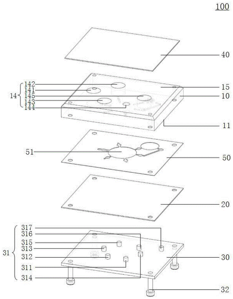
图1为本公开至少一个实施例提供的一种检测芯片的立体结构透视爆炸图,图2为图1所示的检测芯片的立体结构非透视爆炸图,图3为图1所示的检测芯片的立体结构透视图,图4为图1所示的检测芯片的侧视透视图,图5为图1所示的检测芯片的俯视透视图。1 is a perspective exploded view of a three-dimensional structure of a detection chip provided by at least one embodiment of the present disclosure, FIG. 2 is a non-perspective exploded view of the three-dimensional structure of the detection chip shown in FIG. 1 , and FIG. 3 is the detection chip shown in FIG. 1 FIG. 4 is a side perspective view of the detection chip shown in FIG. 1 , and FIG. 5 is a top perspective view of the detection chip shown in FIG. 1 .
下面结合图1-5,对本公开一些实施例提供的检测芯片进行说明。The detection chips provided by some embodiments of the present disclosure will be described below with reference to FIGS. 1-5 .
如图1-3所示,该检测芯片100包括层叠设置的芯片基板10和第一密封膜20。As shown in FIGS. 1-3 , the
芯片基板10包括第一表面11以及位于第一表面11的流体通道12。例如,第一表面11为图1-3中芯片基板10的下表面,流体通道12位于芯片基板10的下表面。例如,芯片基板10的材料为聚丙烯(Polypropylene,PP),且采用注塑工艺加工,通过设计相应的注塑模具,可在芯片基板10的第一表面11上以凹陷的形式形成流体通道12。当然,本公开的实施例不限于此,也可以采用激光雕刻、光刻蚀等任意适用的工艺制作流体通道12。需要说明的是,本公开的实施例中,芯片基板10的材料和加工方式不受限制,这可以根据实际需求而定。The
例如,第一密封膜20覆盖芯片基板10的第一表面11。由于流体通道12以凹陷的形式设置在芯片基板10的第一表面11上,因此第一密封膜20与流体通道12之间可形成液体(例如分析检测所需要的各种试剂)流动空间,例如还可以形成用于试剂反应的空间。例如,第一密封膜20为弹性膜,例如为弹性透明薄膜。例如,第一密封膜20的材料为聚对苯二甲酸乙二醇酯(Polyethylene Terephthalate,PET),以具有较好的弹性和强度,从而在弹性变形之后能够恢复初始状态。当然,本公开的实施例不限于此,第一密封膜20也可以采用其他适用的材料,例如采用聚苯乙烯(Polystyrene,PS)和PET的高分子复合材料,从而具有更好的弹性和强度。For example, the
如图5所示,流体通道12包括多个膜阀部13、提取区121、多条第一支路122、反应区123和多条第二支路124。As shown in FIG. 5 , the
膜阀部13配置为允许第一密封膜20覆盖膜阀部13的部分贴近和分离,从而可对应地关闭和开启流体通道12。例如,在另行提供的部件的作用下(例如挤压),第一密封膜20覆盖膜阀部13的部分被挤压而变形,例如弹性变形,从而贴近芯片基板10(例如与芯片基板10完全贴合),使得第一密封膜20与流体通道12之间的空间在膜阀部13处减小乃至被截断,液体无法通过膜阀部13,从而对应地关闭流体通道12。例如,在另行提供的部件的作用下(例如松开),第一密封膜20覆盖膜阀部13且与芯片基板10贴合的部分形变恢复,从而与芯片基板10分离,使得第一密封膜20与流体通道12之间的空间在膜阀部13处恢复畅通,液体能够通过膜阀部13,从而对应地开启流体通道12。The
例如,膜阀部13为图5所示的圆形凹陷,相应地,另行提供的控制膜阀部13的部件为圆柱状凸起,从而可以对膜阀部13进行挤压。当然,本公开的实施例不限于此,膜阀部13也可以为其他任意适用的形状,例如矩形、六边形、椭圆形等,相应地,另行提供的控制膜阀部13的部件可以为截面形状为矩形、六边形、椭圆形等的柱状凸起,从而可以对膜阀部13进行挤压。For example, the
例如,芯片基板10还包括至少一个储液池14,至少一个储液池14与流体通道12连通。例如,在一些示例中,如图1和图5所示,至少一个储液池14包括多个储液池,例如五个储液池,即第一储液池141、第二储液池142、第三储液池143、第四储液池144和第五储液池145。第一储液池141配置为储存裂解液,第二储液池142配置为储存第一漂洗液,第三储液池143配置为储存第二漂洗液,第四储液池144配置为储存洗脱液,第五储液池145配置为容纳在反应过程中在提取区121中产生的废液。For example, the
例如,多个膜阀部13中至少一个被配置为关闭和开启流体通道12与至少一个储液池14相连通的部分。例如,在一些示例中,如图1和图5所示,多条第一支路122与多个储液池14一一对应连通,多条第一支路122均与提取区121连通。多个膜阀部13包括分别位于多条第一支路122上的多个第一膜阀部131-135,以控制多条第一支路122开启或关闭。多个储液池14中储存的液体可以沿第一支路122进入提取区121,以便于在提取区121中进行提取、漂洗、洗脱等操作。For example, at least one of the plurality of
例如,提取区121包括多个磁珠001,该多个磁珠001活动分布于提取区121中。例如,磁珠001的表面进行了改性处理,将该检测芯片100用于检测时,例如用于对特定的核酸片段进行检测时,磁珠001可以在进行检测时的提取过程中使例如核酸片段等分子结构结合到磁珠001上,以实现提取的功能。例如,上述核酸片段等分子结构是对待检测样品进行裂解后得到的。关于对磁珠001的表面进行改性处理的相关说明可参考常规设计,此处不再详述。For example, the
例如,反应区123通过多条第二支路124分别与提取区121以及多个储液池14中的至少一个连通(例如与第五储液池145连通)。多个膜阀部13还包括分别位于多条第二支路124上的多个第二膜阀部136-137,以控制多条第二支路124开启或关闭。例如,反应区123可以容纳进行提取、漂洗、洗脱等操作之后的反应溶液,并使反应溶液在反应区123中进行扩增反应并进行后续的光学检测。例如,将反应区123与提取区121连通的同时,使反应区123与第五储液池145连通,可以使第五储液池145起到通气孔的作用,以便于反应溶液从提取区121进入反应区123。例如,当反应溶液进入反应区123时,反应区123内的压强增大,反应区123内多余的空气可以通过第二支路124排出到第五储液池145,从而平衡气压,便于反应溶液进入反应区123。For example, the
由此,通过设置多条第一支路122和多条第二支路124,以及对应设置多个第一膜阀部131-135和多个第二膜阀部136-137,可以单独控制各个储液池14是否与提取区121连通,并且控制反应区123是否与提取区121连通,从而可以对检测芯片100进行操作,以实现检测芯片100的功能。In this way, by providing a plurality of
在本公开的实施例中,膜阀部13可以控制流体通道12内的液体通过与否,并且可以作为储液池14的密封阀门以控制何时打开储液池14,释放其中的试剂。由于膜阀部13打开一次所通过的试剂量基本固定,因此膜阀部13还可以定量输送试剂,实现微升级的液体传输。In the embodiment of the present disclosure, the
需要说明的是,虽然图5中示出的提取区121和反应区123为圆形凹陷,但这并不构成对本公开实施例的限制,提取区121和反应区123也可以为其他任意适用的形状的凹陷,例如矩形、六边形、椭圆形等,只要能够形成容纳液体的空间即可,本公开的实施例对此不作限制。It should be noted that although the
膜阀部13、提取区121、第一支路122、反应区123和第二支路124各自的尺寸不受限制,这可以根据实际需求而定,只需保证膜阀部13能够控制第一支路122和第二支路124的开启和关闭即可。The respective sizes of the
需要说明的是,在本公开的实施例中,第一密封膜20例如为弹性透明塑料薄膜(例如PET膜),第一密封膜20具有一定的弹性和强度,对第一密封膜20覆盖提取区121的部分施加正负压(例如正负气压)后被上下推挤和抽拉,因此在流体通道12没有被关闭的情形下,可以定量泵送液体,从而控制液体在各个储液池14、提取区121和反应区123之间流动。由于第一密封膜20较薄,可以实现快速热传导,因此在对反应区123中的反应溶液进行加热时可以较快传递热量,有助于提高热传导效率,以加快扩增反应的速度。第一密封膜20为透明薄膜,使得对反应区123中完成扩增反应的溶液进行光学检测时,光线透过率更高,便于提高光学检测的稳定性及准确性。It should be noted that, in the embodiment of the present disclosure, the
例如,如图1-4所示,在本公开的至少一个实施例中,该检测芯片100还可以进一步包括膜阀密封板30。膜阀密封板30设置在第一密封膜20远离芯片基板10的一侧,例如,膜阀密封板30与第一密封膜20相邻设置。膜阀密封板30包括多个凸起结构31。多个凸起结构31与多个膜阀部13一一对应,且在多个凸起结构31与多个膜阀部13分别彼此接触的情形,关闭流体通道12。For example, as shown in FIGS. 1-4 , in at least one embodiment of the present disclosure, the
例如,多个凸起结构31包括7个凸起结构311-317,相应地,多个膜阀部13也包括7个膜阀部131-137。7个凸起结构311-317与7个膜阀部131-137的分布位置对应,使得各个凸起结构31可以同时对应插入到各个膜阀部13中,从而在各个凸起结构31与各个膜阀部13分别彼此接触的情形(如图4所示),使第一密封膜20覆盖膜阀部13的部分被挤压变形以与芯片基板10完全贴合,进而关闭流体通道12。For example, the plurality of protruding
例如,由于膜阀部13为图5所示的圆形凹陷,因此凸起结构31为圆柱状凸起。当膜阀部13的形状改变时,为了达到较好的配合效果,需要相应改变凸起结构31的形状。For example, since the
例如,膜阀密封板30可以采用螺纹连接(例如螺钉32)、卡接等固定方式固定在芯片基板10上,并使第一密封膜20位于膜阀密封板30与芯片基板10之间。例如,该固定方式为可拆卸的固定方式。例如,在运输过程中或在该检测芯片100被使用前,将膜阀密封板30固定在芯片基板10上,从而可以关闭流体通道12,使各个储液池14中的液体不会泄露或发生串液。当使用该检测芯片100时,将膜阀密封板30与芯片基板10分离,并采用另行提供的装置(例如检测装置,该检测装置包括多个可独立控制的圆柱状凸起)对各个膜阀部13进行控制,从而实现该检测芯片100的功能。For example, the membrane
例如,膜阀密封板30的材料可以采用丙烯腈-丁二烯-苯乙烯(AcrylonitrileButadiene Styrene,ABS)塑料,也可以采用其他适用的材料,本公开的实施例对此不作限制。For example, the material of the membrane
例如,如图1-4所示,在本公开的至少一个实施例中,该检测芯片100还可以进一步包括第二密封膜40。芯片基板10包括与第一表面11相对的第二表面15,第二密封膜40覆盖芯片基板10的第二表面15。例如,第二表面15为图1-4中芯片基板10的上表面,第二密封膜40覆盖芯片基板10的上表面。通过设置第二密封膜40,可以与膜阀部13配合以将储液池14中的液体密封在储液池14中,以防止储液池14中的液体在运输过程中泄露。For example, as shown in FIGS. 1-4 , in at least one embodiment of the present disclosure, the
例如,第二密封膜40为包括层叠的金属箔和高分子材料的复合膜,例如为铝箔和高分子材料的复合膜,从而可以既便于与芯片基板10热压结合,又便于在需要添加样品溶液时被扎破。例如,如图4所示,在使用该检测芯片100时,可以采用另行提供的扎破机构401(例如任意适用的坚硬物品)扎破第二密封膜40,以将样品溶液通过第二密封膜40上的破损口加入第一储液池141。例如,在其他示例中,检测芯片100也可以包括该扎破机构401,以及进一步包括扎破机构固定板402。扎破机构固定板402具有与扎破机构401对应的开口403,扎破机构401设置在该开口403中,扎破机构401可在该开口403中沿开口403的轴向运动。For example, the
例如,如图1-4所示,在本公开的至少一个实施例中,该检测芯片100还可以进一步包括粘接层50。粘接层50设置在芯片基板10与第一密封膜20之间,且配置为使芯片基板10与第一密封膜20彼此粘接。例如,粘接层50可以包括丙烯酸类粘结剂等具有粘结性的材料,例如,可以实现为双面胶。例如,芯片基板10、粘接层50和第一密封膜20具有基本相同的外形轮廓,由此粘接层50可以使芯片基板10和第一密封膜20实现更牢固的结合。For example, as shown in FIGS. 1-4 , in at least one embodiment of the present disclosure, the
例如,粘接层50露出芯片基板10的流体通道12,也即是,粘接层50包括镂空区域51,该镂空区域51的形状与流体通道12在粘接层50上的正投影相同或基本相同,从而便于第一密封膜20与流体通道12形成液体流动和用于试剂反应的空间。For example, the
例如,在其他示例中,当采用超声波焊接、光敏胶粘接、化学溶剂键合或者激光焊接等方式将第一密封膜20结合在芯片基板10上时,可以省略粘接层50。For example, in other examples, when the
图6为本公开至少一个实施例提供的一种检测芯片的反应区的局部放大透视图。例如,如图6所示,反应区123包括多孔结构125,多孔结构125包括多个储液孔002,多个储液孔002配置为储存相同或不同的扩增引物。例如,该扩增引物为冻干试剂,进入到反应区123的反应溶液可将冻干试剂复融,并发生所需的反应(例如扩增反应),以便于在反应结束后进行光学检测。当多个储液孔002储存不同的扩增引物时,进入到各个储液孔002中的反应溶液会发生不同的扩增反应(也即,扩增的对象不同),从而可以检测多种对象(例如不同类型的病毒),以实现多重检测。由于扩增引物为冻干试剂,因此各个储液孔002中储存的扩增引物不会在运输过程中混合,也不会移出储液孔002之外。需要说明的是,本公开的实施例中,储液孔002的截面形状、数量以及分布方式不受限制,这可以根据实际需求而定。6 is a partial enlarged perspective view of a reaction area of a detection chip provided by at least one embodiment of the present disclosure. For example, as shown in FIG. 6, the
下面对该检测芯片100的工作原理进行示例性说明。The working principle of the
在生产过程中,在第一储液池141中预埋裂解液,在第二储液池142中预埋第一漂洗液,在第三储液池143中预埋第二漂洗液,在第四储液池144中预埋洗脱液,第五储液池145空置,在反应区123的储液孔002中预埋扩增引物。将膜阀密封板30安装在芯片基板10上,以使多个凸起结构31与多个膜阀部13分别彼此接触,从而关闭流体通道12,将各个储液池14中的液体密封在各个储液池14中。例如,以待检测样品为人乳头瘤病毒为例,裂解液的成分为盐酸胍、3-(N-吗啡啉)丙磺酸(MOPS)以及聚氧乙烯去水山梨醇单月桂酸酯和聚氧乙烯双去水山梨醇单月桂酸酯的混合物(Tween),第一漂洗液的成分为盐酸胍、MOPS和异丙醇,第二漂洗液的成分为盐酸胍、MOPS和乙醇,洗脱液的成分为三羟甲基氨基甲烷(Tris)和乙二胺四乙酸(EDTA)。During the production process, the lysing solution is pre-embedded in the first
在使用过程中,将膜阀密封板30与芯片基板10分离,并将检测芯片100安装在另行提供的检测装置上。例如,该检测装置包括多个凸起部,多个凸起部与多个膜阀部13一一对应且可以分别单独控制各个膜阀部13。During use, the membrane
首先,将第二密封膜40覆盖第一储液池141的部分扎破,将待检测样品加入到第一储液池141内。例如,可以采用任意适用的坚硬物品扎破第二密封膜40。待检测样品例如为血液、体液等,本公开的实施例对此不作限制。待检测样品在第一储液池141中的裂解液的作用下进行裂解(裂解温域例如可根据实际需求而定),从而裂解得到核酸片段。控制检测装置中的凸起部,以打开第一膜阀部133,并采用检测装置对第一密封膜20覆盖提取区121的部分施加频率较低的正负气压(也可视实际情况仅施加负气压或正气压),从而将第一储液池141中的液体打入到提取区121中。之后,关闭第一膜阀部133。对第一密封膜20覆盖提取区121的部分施加频率较高的正负气压,使得第一密封膜20覆盖提取区121的部分反复振动,从而使提取区121中的液体振动,便于预埋在提取区121中的磁珠001与液体中的核酸片段结合,以实现核酸片段的提取。First, the part of the
然后,控制检测装置中的凸起部,以打开第一膜阀部135,并采用上述施加气压的方式对第一密封膜20覆盖提取区121的部分施加气压,从而将第二储液池142中预埋的第一漂洗液打入到提取区121中。接着关闭第一膜阀部135,并对第一密封膜20覆盖提取区121的部分施加频率较高的正负气压,使得第一密封膜20覆盖提取区121的部分反复振动,从而使提取区121中的液体振动,从而洗掉杂蛋白。然后,打开第一膜阀部134,并采用检测装置中的磁铁吸住提取区121中的磁珠001(例如将磁铁上移以贴近第一密封膜20覆盖提取区121的部分)。对第一密封膜20施加气压以将提取区121中的液体打入第五储液池145。此时,由于磁珠001在磁铁的吸引力下被固定在提取区121中,因此磁珠001上吸附的核酸片段不会随液体进入第五储液池145。例如,第五储液池145作为废液池,用于容纳在提取区121中产生的废液。然后,关闭第一膜阀部134并撤掉磁铁。Then, the protruding part in the detection device is controlled to open the first
接着,打开第一膜阀部132,并采用上述施加气压的方式对第一密封膜20覆盖提取区121的部分施加气压,从而将第三储液池143中预埋的第二漂洗液打入到提取区121中。接着关闭第一膜阀部132,并对第一密封膜20覆盖提取区121的部分施加频率较高的正负气压,使得第一密封膜20覆盖提取区121的部分反复振动,从而使提取区121中的液体振动,从而洗去盐离子和一些小分子。然后,打开第一膜阀部134,并采用检测装置中的磁铁吸住提取区121中的磁珠001。对第一密封膜20覆盖提取区121的部分施加气压,以将提取区121中的液体打入第五储液池145。然后,关闭第一膜阀部134并撤掉磁铁。Next, the
然后,打开第一膜阀部131,并采用上述施加气压的方式对第一密封膜20覆盖提取区121的部分施加气压,从而将第四储液池144中预埋的洗脱液打入到提取区121中。磁珠001上吸附的核酸片段被洗脱液熔解洗脱,与磁珠001分离。接着关闭第一膜阀部131,并打开第二膜阀部136和137。采用上述施加气压的方式对第一密封膜20覆盖提取区121的部分施加气压,将包含有洗脱下来的核酸片段的液体打入到反应区123中。此时将反应区123与第五储液池145连通,以将第五储液池145作为通气孔,便于液体进入反应区123。在将液体打入反应区123的过程中,采用检测装置中的磁铁吸住提取区121中的磁珠001,以避免磁珠001进入反应区123。然后关闭第二膜阀部136和137。Then, the first
最后,打开第一膜阀部134,将检测装置中的磁铁下移以远离第一密封膜20,从而使磁珠001可活动,并随着废液一起被打入第五储液池145。预埋在反应区123的储液孔002中的扩增引物被进入储液孔002的溶液融化。采用检测装置中的温度控制单元对第一密封膜20覆盖反应区123的部分的温度进行控制,使反应区123中的核酸片段进行恒温扩增或者进行聚合酶链式反应(Polymerase Chain Reaction,PCR),之后,通过检测装置的光学检测单元对扩增产物进行分析检测,从而完成检测并得到检测结果。当预埋在多个储液孔002中的扩增引物不同时,可以实现多重检测。Finally, the
通过上述步骤,可以利用该检测芯片100实现待检测样品的分析检测。该检测芯片100结构简单,制作工艺简单,可提高产品良率,降低生产成本,可以定量输送试剂,能够实现多重检测,有助于提高热传导效率和光学检测的稳定性及准确性,并且能够有效防止在运输过程中试剂泄露。Through the above steps, the
本公开至少一实施例还提供一种检测装置,适于操作如本公开任一实施例所述的检测芯片。该检测装置操作前述的检测芯片,可以定量输送试剂,进一步地,其至少一个示例还能够实现多重检测,更进一步地,其至少一个示例还有助于提高热传导效率和光学检测的稳定性及准确性。At least one embodiment of the present disclosure further provides a detection device suitable for operating the detection chip described in any embodiment of the present disclosure. The detection device operates the aforementioned detection chip, and can deliver reagents quantitatively. Further, at least one example of the detection device can also realize multiple detections. Furthermore, at least one example of the detection device can also help to improve the thermal conduction efficiency and the stability and accuracy of optical detection. sex.
图7A为本公开至少一个实施例提供的一种检测装置的示意框图。例如,如图7A所示,检测装置200适于操作上述检测芯片100,该检测装置200包括膜阀控制单元210。FIG. 7A is a schematic block diagram of a detection apparatus provided by at least one embodiment of the present disclosure. For example, as shown in FIG. 7A , the detection device 200 is adapted to operate the
例如,膜阀控制单元210配置为可安装检测芯片100,也即是,将检测芯片100中的膜阀密封板30与芯片基板10分离后,可将检测芯片100安装在膜阀控制单元210上。例如,在一些示例中,在拆卸膜阀密封板30时,将检测芯片100倒置,从而防止膜阀密封板30拆卸后各个储液池14中的液体流出储液池14。将检测芯片100保持倒置的状态并安装在膜阀控制单元210上后,膜阀部13被关闭,然后将检测芯片100连同与膜阀控制单元210接触的结构翻转,以使检测芯片100正置。For example, the membrane
图7B为本公开至少一个实施例提供的一种检测装置的结构示意图,该实施例提供的检测装置例如与图7A所示的检测装置基本相同。例如,膜阀控制单元210包括主体部分212以及设置在该主体部分212上的至少一个凸起部211,该主体部分212具有容纳上述检测芯片100的固定结构,例如通过卡接、粘结等方式固定检测芯片100。至少一个凸起部211可移动(例如相对于主体部分212的突出或收回操作),以在检测芯片100安装在膜阀控制单元210的情形,控制第一密封膜20覆盖膜阀部13的部分是否贴近膜阀部13,或是否从膜阀部13分离,从而可对应地关闭和开启流体通道12。例如,可以通过气动、液压等方式驱动凸起部211,或者可以通过步进电机驱动凸起部211,这些实现驱动的部件设置在膜阀控制单元210的主体部分212之中。FIG. 7B is a schematic structural diagram of a detection apparatus provided by at least one embodiment of the present disclosure. The detection apparatus provided in this embodiment is, for example, basically the same as the detection apparatus shown in FIG. 7A . For example, the membrane
例如,凸起部211的功能可以与前述的凸起结构31的功能类似,也即是,凸起部211可以为多个,且与多个膜阀部13一一对应,以分别控制多个膜阀部13的开启和关闭。在该检测装置200中,膜阀控制单元210可以分别独立控制各个凸起部211,在凸起部211与对应的膜阀部13彼此接触的情形,可关闭流体通道12。For example, the function of the protruding
例如,在一些示例中,凸起部211为7个,并与图1-6所示的检测芯片100中的7个膜阀部131-137的分布位置对应。各个凸起部211可以单独控制,例如可以分别上移,从而可以对应插入到各个膜阀部13中,使第一密封膜20覆盖膜阀部13的部分被挤压变形以与芯片基板10完全贴合,进而关闭流体通道12。当需要打开流体通道12时,使对应的凸起部211下移并远离膜阀部13,第一密封膜20覆盖膜阀部13的部分的形变恢复以与芯片基板10分离,从而可以打开流体通道12。例如,凸起部211可以为圆柱状凸起,从而与圆形的膜阀部13配合工作。For example, in some examples, the number of the protruding
需要说明的是,本公开的实施例中,如上所述,膜阀控制单元210的具体实现方式不受限制,例如可以为液压装置、推进控制机构(例如控制电路或控制芯片)、圆柱体(作为凸起部211)和限位机构的结合,也可以为电机、推进控制机构、圆柱体和限位机构的结合,或者为其他任意的实现方式,这可以根据实际需求而定。It should be noted that, in the embodiments of the present disclosure, as described above, the specific implementation of the membrane
图8为本公开至少一个实施例提供的另一种检测装置的示意框图。例如,如图8所示,除了还进一步包括膜驱动单元220之外,该实施例提供的检测装置200与图7A所示的检测装置200基本相同。在该实施例中,在检测芯片100的流体通道12包括提取区121的情形,膜驱动单元220配置为,在检测芯片100安装在膜阀控制单元210的情形,向第一密封膜20覆盖提取区121的部分施加压力,以使第一密封膜20覆盖提取区121的部分变形,例如反复振动。第一密封膜20覆盖提取区121的部分被上下推挤和抽拉,因此在流体通道12没有被关闭的情形下,可以定量泵送液体,以控制液体在检测芯片100内的流动。FIG. 8 is a schematic block diagram of another detection apparatus provided by at least one embodiment of the present disclosure. For example, as shown in FIG. 8 , the detection device 200 provided in this embodiment is basically the same as the detection device 200 shown in FIG. 7A except that the membrane driving unit 220 is further included. In this embodiment, in the case where the
例如,在一些示例中,膜驱动单元220可以为气压施加单元。膜驱动单元220配置为,在检测芯片100安装在膜阀控制单元210的情形,向第一密封膜20覆盖流体通道12的提取区121的部分施加气压。例如,该气压可以为交替的正气压和负气压,或者仅为正气压或仅为负气压,本公开的实施例对此不作限制。例如,交替的正气压和负气压的变化频率可以调节,从而可以提供频率较高的变化气压和频率较低的变化气压。频率较高的变化气压可使提取区121中的液体振动,从而更好地进行提取、漂洗、洗脱等操作;频率较低的变化气压可以泵送液体,使液体在多个储液池14、提取区121和反应区123之间流动。For example, in some examples, the membrane driving unit 220 may be an air pressure applying unit. The membrane driving unit 220 is configured to apply air pressure to a portion of the
需要说明的是,本公开的实施例中,膜驱动单元220的具体实现方式不受限制,例如可以为气压控制装置、空气压缩机和气体输送管的结合,也可以为其他任意的实现方式,这可以根据实际需求而定。It should be noted that, in the embodiments of the present disclosure, the specific implementation of the membrane drive unit 220 is not limited, for example, it may be a combination of an air pressure control device, an air compressor and a gas delivery pipe, or may be any other implementation. This can be determined according to actual needs.
需要说明的是,本公开的实施例中,检测装置200还可以包括更多的组件和单元,不限于上文描述的膜阀控制单元210和膜驱动单元220。例如,检测装置200还可以包括电源、中央处理器(Central Processing Unit,CPU)、光学检测单元、温度控制单元等,从而使检测装置200具有更完善和更丰富的功能。关于该检测装置200的详细说明和技术效果可以参考上文中关于检测芯片100的描述,此处不再赘述。It should be noted that, in the embodiment of the present disclosure, the detection device 200 may further include more components and units, which are not limited to the membrane
本公开至少一实施例还提供一种检测芯片的使用方法,利用该使用方法可以操作本公开任一实施例所述的检测芯片。利用该使用方法,可以定量输送试剂,进一步地,其至少一个示例还能够实现多重检测,更进一步地,其至少一个示例还有助于提高热传导效率和光学检测的稳定性及准确性。At least one embodiment of the present disclosure further provides a method for using a detection chip, by which the detection chip described in any embodiment of the present disclosure can be operated. Using this method of use, the reagent can be quantitatively delivered, further, at least one example thereof can also realize multiple detection, and further, at least one example thereof can also help to improve the thermal conduction efficiency and the stability and accuracy of optical detection.
图9为本公开至少一个实施例提供的一种检测芯片的使用方法的流程示意图。例如,如图9所示,在一些示例中,该使用方法包括如下操作。FIG. 9 is a schematic flowchart of a method for using a detection chip provided by at least one embodiment of the present disclosure. For example, as shown in FIG. 9, in some examples, the method of use includes the following operations.
步骤S00:提供检测芯片100;Step S00: providing a
步骤S10:控制多个膜阀部13,使第一密封膜20覆盖多个膜阀部13的部分分别从多个膜阀部13分离,从而对应地开启流体通道12。Step S10 : controlling the plurality of
图10为图9所示的检测芯片的使用方法的步骤S10的流程示意图。例如,如图10所示,在一些示例中,在多个膜阀部13包括多个第一膜阀部131-135和多个第二膜阀部136-137、芯片基板10包括多个储液池14、流体通道12包括提取区121和反应区123的情形,上述步骤S10进一步包括如下操作。FIG. 10 is a schematic flowchart of step S10 of the method for using the detection chip shown in FIG. 9 . For example, as shown in FIG. 10 , in some examples, the plurality of
步骤S110:控制多个第一膜阀部131-135,使多个储液池14与提取区121连通,以使多个储液池14中的液体进入提取区121;Step S110: controlling the plurality of first membrane valve parts 131-135 to connect the plurality of
步骤S120:控制多个第二膜阀部136-137,使反应区123与提取区121连通,以使提取区121中的液体进入反应区123。Step S120 : controlling the plurality of second membrane valve parts 136 - 137 to make the
例如,在步骤S110中,可以通过控制第一膜阀部131-135,使多个储液池14与流体通道12的提取区121依序连通(例如在不同的操作阶段分别连通),从而使多个储液池14中的液体依序进入提取区121(例如在不同的操作阶段分别进入提取区121)。For example, in step S110, by controlling the first membrane valve parts 131-135, the plurality of
图11为本公开至少一个实施例提供的另一种检测芯片的使用方法的流程示意图。FIG. 11 is a schematic flowchart of another method for using a detection chip provided by at least one embodiment of the present disclosure.
例如,如图11所示,在一些示例中,该使用方法包括如下操作。For example, as shown in FIG. 11, in some examples, the method of use includes the following operations.
步骤S10:控制多个膜阀部13,使第一密封膜20覆盖多个膜阀部13的部分分别从多个膜阀部13分离,从而对应地开启流体通道12;Step S10 : controlling the plurality of
步骤S20:通过对第一密封膜20覆盖提取区121的部分施加压力,控制检测芯片100中的液体的流动。Step S20 : Control the flow of the liquid in the
例如,该实施例中的步骤S10与图9所示的使用方法的步骤S10基本相同,此处不再赘述。例如,在步骤S20中,该压力可以为交替的正气压和负气压,或者仅为正气压或仅为负气压,这可以根据实际需求而定,本公开的实施例对此不作限制。例如,交替的正气压和负气压的变化频率可以调节,从而可以提供频率较高的变化气压和频率较低的变化气压。频率较高的变化气压可使提取区121中的液体振动,从而更好地进行提取、漂洗、洗脱等操作;频率较低的变化气压可以泵送液体,使液体在多个储液池14、提取区121和反应区123之间流动。For example, step S10 in this embodiment is basically the same as step S10 of the using method shown in FIG. 9 , and details are not repeated here. For example, in step S20, the pressure may be alternate positive air pressure and negative air pressure, or only positive air pressure or only negative air pressure, which may be determined according to actual needs, which is not limited by the embodiments of the present disclosure. For example, the frequency of alternating positive and negative air pressure changes can be adjusted to provide higher frequency changes of air pressure and lower frequency changes of air pressure. The changing air pressure with a higher frequency can make the liquid in the
需要说明的是,本公开的实施例中,该使用方法还可以包括更多的步骤,这可以根据实际需求而定,本公开的实施例对此不作限制。关于该使用方法的详细说明和技术效果可以参考上文中关于检测芯片100和检测装置200的描述,此处不再赘述。It should be noted that, in the embodiments of the present disclosure, the using method may further include more steps, which may be determined according to actual requirements, which are not limited in the embodiments of the present disclosure. For the detailed description and technical effect of the method of use, reference may be made to the above description of the
有以下几点需要说明:The following points need to be noted:
(1)本公开实施例附图只涉及到本公开实施例涉及到的结构,其他结构可参考通常设计。(1) The drawings of the embodiments of the present disclosure only relate to the structures involved in the embodiments of the present disclosure, and other structures may refer to general designs.
(2)在不冲突的情况下,本公开的实施例及实施例中的特征可以相互组合以得到新的实施例。(2) The embodiments of the present disclosure and features in the embodiments may be combined with each other to obtain new embodiments without conflict.
以上所述,仅为本公开的具体实施方式,但本公开的保护范围并不局限于此,本公开的保护范围应以所述权利要求的保护范围为准。The above descriptions are only specific embodiments of the present disclosure, but the protection scope of the present disclosure is not limited thereto, and the protection scope of the present disclosure should be subject to the protection scope of the claims.
Claims (15)
Priority Applications (3)
| Application Number | Priority Date | Filing Date | Title |
|---|---|---|---|
| CN202010104016.2A CN113275044B (en) | 2020-02-20 | 2020-02-20 | Detection chip, use method thereof and detection device |
| US17/622,277 US12397292B2 (en) | 2020-02-20 | 2021-02-01 | Detection chip, method for using detection chip, and detection device |
| PCT/CN2021/074635 WO2021164530A1 (en) | 2020-02-20 | 2021-02-01 | Detection chip and usage method therefor, and detection apparatus |
Applications Claiming Priority (1)
| Application Number | Priority Date | Filing Date | Title |
|---|---|---|---|
| CN202010104016.2A CN113275044B (en) | 2020-02-20 | 2020-02-20 | Detection chip, use method thereof and detection device |
Publications (2)
| Publication Number | Publication Date |
|---|---|
| CN113275044A CN113275044A (en) | 2021-08-20 |
| CN113275044B true CN113275044B (en) | 2022-07-12 |
Family
ID=77274949
Family Applications (1)
| Application Number | Title | Priority Date | Filing Date |
|---|---|---|---|
| CN202010104016.2A Active CN113275044B (en) | 2020-02-20 | 2020-02-20 | Detection chip, use method thereof and detection device |
Country Status (3)
| Country | Link |
|---|---|
| US (1) | US12397292B2 (en) |
| CN (1) | CN113275044B (en) |
| WO (1) | WO2021164530A1 (en) |
Families Citing this family (6)
| Publication number | Priority date | Publication date | Assignee | Title |
|---|---|---|---|---|
| CN116493063B (en) * | 2022-01-21 | 2024-04-16 | 广州国家实验室 | Liquid transfer device and multi-channel liquid transfer device |
| CN114570449B (en) * | 2022-04-26 | 2022-08-16 | 广州国家实验室 | Liquid transfer device and multi-path parallel liquid transfer device |
| CN115007228B (en) * | 2022-05-07 | 2024-01-30 | 合肥诺迈基生物科技有限公司 | POCT micro-fluidic chip, detection system, detection method and application |
| CN115646563A (en) * | 2022-10-14 | 2023-01-31 | 广州迪澳医疗科技有限公司 | Micro-fluidic chip and preparation method thereof |
| CN115591594B (en) * | 2022-11-10 | 2025-07-01 | 铭汰医药设备(上海)有限公司 | Microfluidic Chips for Drug Delivery Systems |
| CN116510796A (en) * | 2023-04-21 | 2023-08-01 | 季华实验室 | Liquid drop control chip and preparation method and application method thereof |
Citations (5)
| Publication number | Priority date | Publication date | Assignee | Title |
|---|---|---|---|---|
| CN101750488A (en) * | 2008-12-17 | 2010-06-23 | 中国科学院大连化学物理研究所 | Beta 2-adrenergic receptor stimulant detection method based on microfluidic chip |
| CN101750489A (en) * | 2008-12-17 | 2010-06-23 | 中国科学院大连化学物理研究所 | Beta 2-adrenergic receptor stimulant detection method based on microfluidic chip |
| CN105349401A (en) * | 2015-10-14 | 2016-02-24 | 安徽易康达光电科技有限公司 | Multifunctional integrated microfluidic nucleic acid analysis chip and preparation and analysis method thereof |
| CN205127987U (en) * | 2015-09-24 | 2016-04-06 | 基蛋生物科技股份有限公司 | Micro -fluidic chip for multi -index detection |
| WO2017030455A1 (en) * | 2015-08-18 | 2017-02-23 | Curiosity Diagnostics Sp. Z O.O. | Microfluidic chip with pressure and flow control system |
Family Cites Families (9)
| Publication number | Priority date | Publication date | Assignee | Title |
|---|---|---|---|---|
| US20050266582A1 (en) * | 2002-12-16 | 2005-12-01 | Modlin Douglas N | Microfluidic system with integrated permeable membrane |
| US8715446B2 (en) * | 2004-10-13 | 2014-05-06 | Rheonix, Inc. | Latent solvent-based microfluidic apparatus, methods, and applications |
| US20100291588A1 (en) * | 2005-06-24 | 2010-11-18 | The Board Of Regents Of The University Of Texas System | Systems and methods including self-contained cartridges with detection systems and fluid delivery systems |
| JP2010513790A (en) * | 2006-12-19 | 2010-04-30 | コーニンクレッカ フィリップス エレクトロニクス エヌ ヴィ | Microfluidic device |
| EP2661485A4 (en) * | 2011-01-06 | 2018-11-21 | Meso Scale Technologies, LLC | Assay cartridges and methods of using the same |
| US20150093838A1 (en) * | 2013-10-01 | 2015-04-02 | James P. Landers | Microfluidic valve systems |
| MX379999B (en) * | 2014-12-31 | 2025-03-11 | Visby Medical Inc | DEVICES AND METHODS FOR MOLECULAR DIAGNOSTIC TESTING |
| EP3288681A1 (en) * | 2015-04-30 | 2018-03-07 | Orphidia Limited | Microfluidic valves and devices |
| CN108816300B (en) | 2018-07-02 | 2020-05-01 | 京东方科技集团股份有限公司 | Microfluidic chip, functional device and manufacturing method thereof |
-
2020
- 2020-02-20 CN CN202010104016.2A patent/CN113275044B/en active Active
-
2021
- 2021-02-01 WO PCT/CN2021/074635 patent/WO2021164530A1/en not_active Ceased
- 2021-02-01 US US17/622,277 patent/US12397292B2/en active Active
Patent Citations (5)
| Publication number | Priority date | Publication date | Assignee | Title |
|---|---|---|---|---|
| CN101750488A (en) * | 2008-12-17 | 2010-06-23 | 中国科学院大连化学物理研究所 | Beta 2-adrenergic receptor stimulant detection method based on microfluidic chip |
| CN101750489A (en) * | 2008-12-17 | 2010-06-23 | 中国科学院大连化学物理研究所 | Beta 2-adrenergic receptor stimulant detection method based on microfluidic chip |
| WO2017030455A1 (en) * | 2015-08-18 | 2017-02-23 | Curiosity Diagnostics Sp. Z O.O. | Microfluidic chip with pressure and flow control system |
| CN205127987U (en) * | 2015-09-24 | 2016-04-06 | 基蛋生物科技股份有限公司 | Micro -fluidic chip for multi -index detection |
| CN105349401A (en) * | 2015-10-14 | 2016-02-24 | 安徽易康达光电科技有限公司 | Multifunctional integrated microfluidic nucleic acid analysis chip and preparation and analysis method thereof |
Also Published As
| Publication number | Publication date |
|---|---|
| WO2021164530A1 (en) | 2021-08-26 |
| CN113275044A (en) | 2021-08-20 |
| US12397292B2 (en) | 2025-08-26 |
| US20220250067A1 (en) | 2022-08-11 |
Similar Documents
| Publication | Publication Date | Title |
|---|---|---|
| CN113275044B (en) | Detection chip, use method thereof and detection device | |
| CN113275046B (en) | Detection chip, method for using the same, and detection device | |
| JP6698786B2 (en) | Single-Structure Biochip and Manufacturing Method Providing Process from Sample Introduction to Results Output | |
| US11612893B2 (en) | Unitary biochip providing sample-in to results-out processing and methods of manufacture | |
| EP1979097B1 (en) | Flexible and modular microfluidic device | |
| CN111621417B (en) | Microfluidic chip for biological sample processing and application method thereof | |
| CN105873681A (en) | Cartridges and Instruments for Sample Analysis | |
| CN115537288A (en) | Microfluidic nucleic acid extraction detection box and detection system | |
| CN114471751A (en) | Detection chip, its operation method, and detection device | |
| AU2013204387A1 (en) | Unitary biochip providing sample-in to results-out processing and methods of manufacture | |
| AU2020202163A1 (en) | Unitary biochip providing sample-in to results-out processing and methods of manufacture | |
| JP5898635B2 (en) | Method for producing nucleic acid analysis cartridge | |
| CN120644259B (en) | Microfluidic chips and sample detection methods | |
| AU2007207681B2 (en) | Microfluidic chips and assay systems | |
| CN119614357A (en) | A microfluidic chip for detecting potato-derived ingredients | |
| HK40033584A (en) | Biochip with reagent storage | |
| HK40033584B (en) | Biochip with reagent storage | |
| HK1181113A (en) | Unitary biochip providing sample-in to results-out processing and methods of manufacture |
Legal Events
| Date | Code | Title | Description |
|---|---|---|---|
| PB01 | Publication | ||
| PB01 | Publication | ||
| SE01 | Entry into force of request for substantive examination | ||
| SE01 | Entry into force of request for substantive examination | ||
| GR01 | Patent grant | ||
| GR01 | Patent grant |