CN113263477A - Staple bolt mounting tool for floor heating coil pipe - Google Patents
Staple bolt mounting tool for floor heating coil pipe Download PDFInfo
- Publication number
- CN113263477A CN113263477A CN202110643692.1A CN202110643692A CN113263477A CN 113263477 A CN113263477 A CN 113263477A CN 202110643692 A CN202110643692 A CN 202110643692A CN 113263477 A CN113263477 A CN 113263477A
- Authority
- CN
- China
- Prior art keywords
- magazine
- staple
- pair
- floor heating
- gun cover
- Prior art date
- Legal status (The legal status is an assumption and is not a legal conclusion. Google has not performed a legal analysis and makes no representation as to the accuracy of the status listed.)
- Pending
Links
Images


Classifications
-
- B—PERFORMING OPERATIONS; TRANSPORTING
- B25—HAND TOOLS; PORTABLE POWER-DRIVEN TOOLS; MANIPULATORS
- B25C—HAND-HELD NAILING OR STAPLING TOOLS; MANUALLY OPERATED PORTABLE STAPLING TOOLS
- B25C5/00—Manually operated portable stapling tools; Hand-held power-operated stapling tools; Staple feeding devices therefor
-
- B—PERFORMING OPERATIONS; TRANSPORTING
- B25—HAND TOOLS; PORTABLE POWER-DRIVEN TOOLS; MANIPULATORS
- B25C—HAND-HELD NAILING OR STAPLING TOOLS; MANUALLY OPERATED PORTABLE STAPLING TOOLS
- B25C7/00—Accessories for nailing or stapling tools, e.g. supports
Landscapes
- Engineering & Computer Science (AREA)
- Mechanical Engineering (AREA)
- Portable Nailing Machines And Staplers (AREA)
Abstract
The invention discloses a staple mounting tool for a floor heating coil, which comprises: the bottom end of one side of the magazine is provided with a nail outlet; the nail feeding module is arranged inside the magazine; the nailing module is arranged at the top end of one side of the magazine. The gun body of the invention is 100g in total and is very light. Can greatly reduce the construction strength and improve the construction efficiency in use. The shell is not easy to be clamped. If the shell is blocked due to improper operation, the gun cover can be easily disassembled, and the clamped staple can be taken out. The loading capacity is large, and 40 staples can be loaded at one time. The common staple bolts in the market are all suitable. The high-strength modified ABS is adopted, so that the strength is high and the durability is high. The staple bolt is ally oneself with to the cooperation, and dress one row of staple bolt only needs 10~20 seconds efficiency of construction to promote. On average a two-quarters site can save 1 hour. The tool staple is stronger than a manual staple (the manual staple is 90 percent at present in China).
Description
Technical Field
The invention relates to the technical field of staple bolt installation equipment for a floor heating coil, in particular to a staple bolt installation tool for the floor heating coil.
Background
In the prior art, staple bolt installation tools are divided into two types, and one type is manually driven by a staple bolt gun for standing construction of a metal structure. Still another category is conceptualized tools, driven pneumatically or electrically (battery or plug-in). Disadvantages of the first staple gun: the weight of the metal material is 3-4 kg, so that the construction is clumsy; when the clamping nail is used, the clamping nail is easy to clamp the shell and is difficult to take out once being clamped, and the use efficiency is seriously influenced. And even the tool itself; the cost is high, generally several hundreds to one thousand are different; there are many limitations on staple design, and a dedicated staple is generally used. The staple bolts cannot be used universally and cannot be produced in mass, so the manufacturing cost is high; the metal piece is matched with the plastic piece, and the plastic piece is easy to damage. The second staple gun has the following disadvantages: at present, only pneumatic is available on the market, but the manufacturing cost is high, and the nail gun and the air pump need 1000 +; the pneumatic power is heavy, and the weight is generally 3-5 kg; the nail gun and the air pump are connected by a pipeline, so that the construction is inconvenient. Similar problems exist with plug-in electricity; the magazine is small, the amount of nails to be clamped at one time is small, and the nails need to be frequently changed during construction; the battery capacity required for installing the battery is large, otherwise, the construction is easy to be dead, but the battery capacity and the weight are contradictory. Generally speaking, it is heavy, inefficient and expensive. A staple mounting tool for a floor heating coil is designed.
Disclosure of Invention
According to an embodiment of the present invention, there is provided a staple attaching tool for a floor heating coil, including:
the bottom end of one side of the magazine is provided with a nail outlet;
the nail feeding module is arranged inside the magazine;
the nailing module is arranged at the top end of one side of the magazine.
Further, the staple feeding module comprises:
the slide mounting groove is formed in the bottom end of the interior of the magazine;
the slideway is arranged at the top of the slideway mounting groove and is connected with the magazine;
the sliding block is arranged on the slide way;
the elastic component is respectively connected with the sliding block and the sliding way.
Further, the elastic member includes:
the pulley is movably arranged on one side inside the slideway;
the one end of rubber band is connected at the bottom opposite side of slide, and the other end of rubber band just is connected with the slider through the top of the bottom of slide, pulley and slide in proper order.
Further, the nailing module includes:
the gun cover is arranged at the top end of one side of the magazine;
the resetting component is connected with the gun cover and the magazine;
the limiting assembly is connected with the gun cover and the magazine;
the staple pin, the staple pin setting is at the inside top of rifle lid.
Further, the reset assembly comprises:
the spring hole is formed in the end part of the magazine;
the spring column is arranged inside the gun cover and is ejected out;
the spring is sleeved on the spring post, and the spring post and the spring are inserted into the spring hole.
Further, the spacing subassembly contains:
the pair of limiting clamping grooves are symmetrically formed in the outer wall of the magazine;
a pair of spacing buckle, a pair of spacing buckle symmetry joint is in the both sides of rifle lid, a pair of spacing buckle respectively with a pair of spacing draw-in groove joint.
Further, the nailing module further comprises:
the pair of guide grooves are symmetrically formed in the outer wall of the magazine;
the pair of guide blocks are symmetrically arranged on the inner wall of the gun cover, and the pair of guide grooves are respectively connected into the pair of guide grooves in a sliding manner.
Further, the nailing module further comprises:
the lock catch is arranged at the bottom end of the lock catch;
the hasp stopper, the hasp stopper sets up the bottom at the magazine.
Further, the nailing module further comprises:
the flattening device is arranged at the top end of the inner part of the gun cover and is connected with the staple bolt for flattening the staple bolt.
Further, the method also comprises the following steps:
the pair of staple bolt limiting blocks are symmetrically arranged on the inner wall of the magazine;
the pair of observation ports are symmetrically formed in the outer wall of the magazine and are respectively positioned on the same vertical line with the pair of staple bolt limiting blocks;
the arc-shaped limiting block is arranged on the inner wall of the magazine;
supporting legs, the supporting legs setting is in the bottom of magazine.
According to the staple mounting tool for the floor heating coil, the gun body is 100g in total, and the weight is very light. Can greatly reduce the construction strength and improve the construction efficiency in use. The shell is not easy to be clamped. If the shell is blocked due to improper operation, the gun cover can be easily disassembled, and the clamped staple can be taken out. The loading capacity is large, and 40 staples can be loaded at one time. The common staple bolts in the market are all suitable. The high-strength modified ABS is adopted, so that the strength is high and the durability is high. The staple bolt is ally oneself with to the cooperation, and dress one row of staple bolt only needs 10~20 seconds efficiency of construction to promote. On average a two-quarters site can save 1 hour. The tool staple is stronger than a manual staple (the manual staple is 90 percent at present in China).
It is to be understood that both the foregoing general description and the following detailed description are exemplary and are intended to provide further explanation of the claimed technology.
Drawings
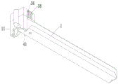
Fig. 1 is a schematic perspective view illustrating a staple installing tool for a floor heating coil according to an embodiment of the present invention.
Fig. 2 is a schematic view of a gun cover of a staple mounting tool for a floor heating coil according to an embodiment of the present invention, in a disassembled configuration from the bottom.
Fig. 3 is a schematic perspective view of a magazine of a staple mounting tool for a floor heating coil according to an embodiment of the present invention.
Fig. 4 is an exploded view illustrating a clip installation tool for a floor heating coil according to an embodiment of the present invention.
Fig. 5 is a schematic perspective view of a clip installation tool for a floor heating coil at a slide way according to an embodiment of the present invention.
Fig. 6 is a schematic view of a magazine bottom view of a staple mounting tool for a floor heating coil according to an embodiment of the present invention.
Fig. 7 is a schematic side view of a magazine of a staple mounting tool for a floor heating coil according to an embodiment of the present invention.
Detailed Description
The present invention will be further explained by describing preferred embodiments of the present invention in detail with reference to the accompanying drawings.
First, a staple installation tool for a floor heating coil according to an embodiment of the present invention will be described with reference to fig. 1 to 7, where the application scenarios of staple installation for a floor heating coil are wide.
As shown in fig. 1 to 7, a staple attaching tool for a floor heating coil according to an embodiment of the present invention includes a magazine 1, a staple feeding module, and a nailing module.
Specifically, as shown in fig. 1 and 3, a nail outlet 11 is arranged at the bottom end of one side of the magazine 1; the nail feeding module is arranged in the magazine 1; the nailing module is arranged at the top end of one side of the magazine 1; magazine 1 is used for depositing the bail, and the module of sending the nail is used for carrying out automatic propelling movement to the bail in magazine 1, and the nailing module is used for beating out the bail in magazine 1 through going out nail mouth 11 to fix the floor heating coil on the heated board, greatly reduced construction strength with promote the efficiency of construction, and the instrument bail is more firm than manual bail (at present 90% are manual bail at home).
Further, as shown in fig. 1 to 5, the nail feeding module includes: a slide mounting groove 21, a slide 22, a slide 23 and an elastic component. In the present embodiment, the chute mounting groove 21 is provided at the inner bottom end of the magazine 1; the slide way 22 is arranged at the top of the slide way mounting groove 21 and is connected with the magazine 1; the slide block 23 is arranged on the slide way 22; elastic component connects slider 23 and slide 22 respectively, slide mounting groove 21 is used for fixing a position the installation of slide 22, thereby be convenient for slide 22's installation, and slide 22 still passes magazine 1 and slip fixed connection together through the screw hole of 1 bottom of screw, slider 23 slides of direction on slide 22, elastic component is used for providing elasticity for slider 23, make slider 23 pass through elastic component's elasticity and let the bail can receive propelling force in magazine 1 always, be equipped with slider 23 spacing groove on slide 22's the end, can be spacing on slider 23 spacing groove, make slider 23 can not receive the influence of rubber band 25 and keep motionless, make things convenient for the installation of bail, slide 22's upper and lower two parts also all are equipped with rubber band 25 standing groove, protection rubber band 25.
Further, as shown in fig. 1 to 5, the elastic member includes: pulley 24 and rubber band 25. In the present embodiment, the pulley 24 is movably installed at one side of the inside of the slideway 22; one end of the rubber band 25 is connected to the other side of the bottom end of the slide way 22, and the other end of the rubber band 25 passes through the bottom end of the slide way 22, the pulley 24 and the top end of the slide way 22 in sequence and is connected with the sliding block 23; the pulley 24 is used for reducing friction force and preventing the rubber band 25 with excessive friction force from being easily damaged, and the rubber band 25 is used for providing elastic force for the sliding block 23 and enabling the sliding block 23 to slide in the slide way 22.
Further, as shown in fig. 1 to 2 and 4, the nailing module includes: gun cap 31, reset assembly, stop assembly and staple needle 32. In the embodiment, the gun cover 31 is arranged at the top end of one side of the magazine 1; the reset component is connected with the gun cover 31 and the magazine 1; the limiting assembly is connected with the gun cover 31 and the magazine 1; the card nail needle 32 sets up on the inside top of rifle lid 31, makes the card thimble extrude the bail downwards through pressing rifle lid 31 to beat the bail, it is fixed to the floor heating coil, and reset assembly is used for providing certain reseing for rifle lid 31, lets rifle lid 31 press after can automatic bounce reset, carries out next time pressing, and spacing subassembly is used for spacing rifle lid 31, breaks away from magazine 1 when preventing that rifle lid 31 from resetting and bounces.
Further, as shown in fig. 2 and 4, the reset assembly includes: spring hole 33, spring post 34 and spring 35. In the present embodiment, the spring hole 33 is opened at the end of the magazine 1; the spring column 34 is arranged inside the gun cover 31 and is ejected out; spring 35 suit is on spring post 34, and spring post 34 and spring 35 insert in spring hole 33, and spring hole 33 is used for placing spring 35, and spring post 34 plays the effect of direction, and spring 35 is used for providing elasticity for can be through the elasticity automatic re-setting of spring 35 bounce after rifle lid 31 pushes down.
Further, as shown in fig. 1 to 4 and 6 to 7, the limiting component comprises: a pair of limit slots 36 and a pair of limit snaps 37. In this embodiment, a pair of limiting slots 36 are symmetrically formed on the outer wall of the magazine 1; the pair of limiting buckles 37 are symmetrically clamped on two sides of the gun cover 31, and the pair of limiting buckles 37 are respectively clamped with the pair of limiting clamping grooves 36. Through a pair of spacing buckle 37 joint on a pair of spacing draw-in groove 36, can reset the rifle lid 31 and bounce the time and carry on spacingly, thereby prevent to pop out on rifle lid 31 magazine 1.
Further, as shown in fig. 2, 6-7, the nailing module further comprises: a pair of guide grooves 38 and a pair of guide blocks 39. In the present embodiment, a pair of guide grooves 38 are symmetrically opened on the outer wall of the magazine 1; a pair of guide blocks 39 are symmetrically arranged on the inner wall of the gun cover 31, and a pair of guide grooves 38 are respectively connected in a sliding manner in the pair of guide grooves 38, so that the gun cover 31 can perform guide movement on the magazine 1.
Further, as shown in fig. 2, 6-7, the nailing module further comprises: a latch 40 and a latch stop 41. In the present embodiment, the lock 40 is disposed at the bottom end of the lock 40; the lock catch limiting block 41 is arranged at the bottom end of the magazine 1. Can lock the rifle lid 31 on magazine 1 through being equipped with hasp 40 to when using, guarantee the stability of equipment, also reduce the space that occupies, hasp stopper 41 is used for spacing when locking hasp 40, prevents that hasp 40 from rotating to float too big and causing the locking insecure.
Further, as shown in fig. 2, in the present embodiment, the nailing module further includes: and the flattening device 42 is arranged at the top end of the inner part of the gun cover 31, is connected with the staple pin 32 and is used for flattening the staple so as to prevent the staple from being clamped.
Further, as shown in fig. 3 and 7, in the present embodiment, the method further includes: a pair of staple stoppers 12, a pair of viewing ports 13, an arc stopper 14 and a supporting foot 15. A pair of staple bolt limiting blocks 12 are symmetrically arranged on the inner wall of the magazine 1; the pair of observation ports 13 are symmetrically formed in the outer wall of the magazine 1 and are respectively positioned on the same vertical line with the pair of staple bolt limiting blocks 12; the arc-shaped limiting block 14 is arranged on the inner wall of the magazine 1; the supporting legs 15 are arranged at the bottom end of the magazine 1; the pair of staple bolt stoppers 12 are used for spacing the staple bolt, guarantee the accuracy of going up bullet (going up the staple bolt), prevent to take place the phenomenon that the staple bolt blocked, and a pair of viewing aperture 13 is used for observing the staple bolt, sees whether the staple bolt takes place the phenomenon of blocking, and arc stopper 14 is used for spacing slider 23, prevents that slider 23 is located the last of slide 22 and drops down, and supporting legs 15 plays the supporting role, the staple bolt of being convenient for play out.
When the rapid nailing machine is used, the gun cover 31 and the magazine 1 are not locked together by rotating the lock catch 40, the gun cover 31 bounces upwards by the elastic force of the spring 35, namely, the rapid nailing machine is in an open state, then the slide block 23 is pulled to the tail end of the slide way 22 for limiting and fixing, a special continuous row of staples are fixed on the slide way 22, then the slide block 23 is pulled, the slide block 23 supports against the staples by the contraction force of the rubber band 25, adhesive tapes on the continuous row of staples are torn off, then the gun cover 31 of the continuous row of staples is held by a hand, the staple can be shot out of the fixed floor heating coil through the staple outlet 11 by pressing the gun cover 31 downwards, then the gun cover 31 is released and is not pressed any more, the gun cover 31 can reset and bounces up by the elastic force of the spring 35, the staples can be pushed forwards by the slide block 23 for next nailing, so that the staples are sequentially nailed, after the use, the gun cover 31 is, the gun cover 31 can be locked to lock the device.
When parts need to be replaced, the gun cover 31 and the magazine 1 are not locked together by rotating the lock catch 40, the gun cover 31 is bounced upwards by the elastic force of the spring 35, namely in an open state, then the gun cover 31 is slightly pulled outwards, the gun cover 31 and the magazine 1 can be taken down, then a screw on a screw hole at the bottom of the magazine 1 is screwed down by a screwdriver, the slide way 22 is taken down, the slide block 23 on the slide way 22 is taken down, the old rubber band 25 is taken down, then a new rubber band 25 is tied up, the new rubber band 25 is respectively fixed at corresponding positions of the slide way 22 and the slide block 23, then the slide block 23 is sleeved on the slide way 22 again, the slide way 22 is fixed through the screw, the gun cover 31 is installed on the magazine 1, the gun cover 31 is pressed to the lowest position, then the lock catch 40 is rotated to the bottom of the magazine 1, the gun cover 31 can be locked, and the device can be locked.
In the above, referring to fig. 1 to 7, a staple mounting tool for a floor heating coil according to an embodiment of the present invention is described, and the gun body is 100g in total and is very light. Can greatly reduce the construction strength and improve the construction efficiency in use. The shell is not easy to be clamped. If the shell is blocked due to improper operation, the gun cover 31 can be easily disassembled to take out the blocked staple. The loading capacity is large, and 40 staples can be loaded at one time. The common staple bolts in the market are all suitable. The high-strength modified ABS is adopted, so that the strength is high and the durability is high. The staple bolt is ally oneself with to the cooperation, and dress one row of staple bolt only needs 10~20 seconds efficiency of construction to promote. On average a two-quarters site can save 1 hour. The tool staple is stronger than a manual staple (the manual staple is 90 percent at present in China).
It should be noted that, in the present specification, the terms "comprises," "comprising," or any other variation thereof, are intended to cover a non-exclusive inclusion, such that a process, method, article, or apparatus that comprises a list of elements does not include only those elements but may include other elements not expressly listed or inherent to such process, method, article, or apparatus. Without further limitation, an element defined by the phrase "comprising … …" does not exclude the presence of other identical elements in a process, method, article, or apparatus that comprises the element.
While the present invention has been described in detail with reference to the preferred embodiments, it should be understood that the above description should not be taken as limiting the invention. Various modifications and alterations to this invention will become apparent to those skilled in the art upon reading the foregoing description. Accordingly, the scope of the invention should be determined from the following claims.
Claims (10)
Priority Applications (1)
| Application Number | Priority Date | Filing Date | Title |
|---|---|---|---|
| CN202110643692.1A CN113263477A (en) | 2021-06-09 | 2021-06-09 | Staple bolt mounting tool for floor heating coil pipe |
Applications Claiming Priority (1)
| Application Number | Priority Date | Filing Date | Title |
|---|---|---|---|
| CN202110643692.1A CN113263477A (en) | 2021-06-09 | 2021-06-09 | Staple bolt mounting tool for floor heating coil pipe |
Publications (1)
| Publication Number | Publication Date |
|---|---|
| CN113263477A true CN113263477A (en) | 2021-08-17 |
Family
ID=77234759
Family Applications (1)
| Application Number | Title | Priority Date | Filing Date |
|---|---|---|---|
| CN202110643692.1A Pending CN113263477A (en) | 2021-06-09 | 2021-06-09 | Staple bolt mounting tool for floor heating coil pipe |
Country Status (1)
| Country | Link |
|---|---|
| CN (1) | CN113263477A (en) |
Citations (8)
| Publication number | Priority date | Publication date | Assignee | Title |
|---|---|---|---|---|
| JP3059033U (en) * | 1998-11-11 | 1999-07-02 | 偉全企業股▲ふん▼有限公司 | Stepless staple pushing structure |
| CN2423069Y (en) * | 2000-05-16 | 2001-03-14 | 深圳市龙岗区龙岗南约旗标实业厂 | Lock mechanism for drilling machine |
| KR200313522Y1 (en) * | 2003-02-19 | 2003-05-16 | 남기철 | Fixing pin Tacker |
| CN101058177A (en) * | 2006-04-19 | 2007-10-24 | 上海坚明办公用品有限公司 | Nail catcher |
| JP3147296U (en) * | 2008-09-19 | 2008-12-25 | 允暢五金工具股▲ふん▼有限公司 | Nailer |
| CN202491279U (en) * | 2012-04-11 | 2012-10-17 | 郭陶 | Special stapling gun for geothermal tube |
| CN109108904A (en) * | 2018-10-30 | 2019-01-01 | 广东美特机械有限公司 | A kind of floor heating nail gun feeding device for nail |
| CN214870324U (en) * | 2021-06-09 | 2021-11-26 | 上海绿羽节能科技有限公司 | Staple installation tool for floor heating coil |
-
2021
- 2021-06-09 CN CN202110643692.1A patent/CN113263477A/en active Pending
Patent Citations (8)
| Publication number | Priority date | Publication date | Assignee | Title |
|---|---|---|---|---|
| JP3059033U (en) * | 1998-11-11 | 1999-07-02 | 偉全企業股▲ふん▼有限公司 | Stepless staple pushing structure |
| CN2423069Y (en) * | 2000-05-16 | 2001-03-14 | 深圳市龙岗区龙岗南约旗标实业厂 | Lock mechanism for drilling machine |
| KR200313522Y1 (en) * | 2003-02-19 | 2003-05-16 | 남기철 | Fixing pin Tacker |
| CN101058177A (en) * | 2006-04-19 | 2007-10-24 | 上海坚明办公用品有限公司 | Nail catcher |
| JP3147296U (en) * | 2008-09-19 | 2008-12-25 | 允暢五金工具股▲ふん▼有限公司 | Nailer |
| CN202491279U (en) * | 2012-04-11 | 2012-10-17 | 郭陶 | Special stapling gun for geothermal tube |
| CN109108904A (en) * | 2018-10-30 | 2019-01-01 | 广东美特机械有限公司 | A kind of floor heating nail gun feeding device for nail |
| CN214870324U (en) * | 2021-06-09 | 2021-11-26 | 上海绿羽节能科技有限公司 | Staple installation tool for floor heating coil |
Similar Documents
| Publication | Publication Date | Title |
|---|---|---|
| US9452514B2 (en) | Fastener installation tool for roof truss framing and construction system | |
| US3930297A (en) | Fastener feed apparatus and method | |
| US20080179371A1 (en) | Portable fastener driving device | |
| US4014488A (en) | Fastener feed apparatus and method | |
| US10859109B2 (en) | Fastener for installation tool for roof truss framing and construction system | |
| US10124470B2 (en) | Fastener installation tool adaptor | |
| CN214870324U (en) | Staple installation tool for floor heating coil | |
| US11975424B2 (en) | Multiple entry angle adaptor with locator for fastener installation tool | |
| US10603768B2 (en) | Installation tool/fastener system for roof truss framing and construction | |
| EP1011929A1 (en) | Fastener feeding system for power actuated gun | |
| US8424420B2 (en) | Fastener tool and feeder assembly therefor | |
| CN113263477A (en) | Staple bolt mounting tool for floor heating coil pipe | |
| US20070090146A1 (en) | Coil-type magazine for nail gun | |
| TW200819261A (en) | Cap nailer and feed system | |
| US7273160B2 (en) | Nailer magazine | |
| CN110541903B (en) | Power storage torsion spring and nail gun with said power storage torsion spring | |
| WO2018034986A1 (en) | Fastener installation tool adaptor | |
| JP2008025840A (en) | Cap juxtaposition system | |
| CN216299198U (en) | Cartridge clip connecting structure of hand-held type nail-shooting fastening tool | |
| JP2008023707A (en) | Cap bypass feeding mechanism | |
| CN210678582U (en) | Nail holding device | |
| KR101579294B1 (en) | Tacker | |
| US20050217186A1 (en) | Strap attachment device | |
| US20150239113A1 (en) | Metal Connector Adaptor for a Fastening Tool | |
| CA2219048C (en) | Fastener-driving tool assembly with improved fastener-loading features |
Legal Events
| Date | Code | Title | Description |
|---|---|---|---|
| PB01 | Publication | ||
| PB01 | Publication | ||
| SE01 | Entry into force of request for substantive examination | ||
| SE01 | Entry into force of request for substantive examination | ||
| RJ01 | Rejection of invention patent application after publication |
Application publication date: 20210817 |
|
| RJ01 | Rejection of invention patent application after publication |