CN113245592B - Equipment for producing and drilling bearing plate - Google Patents
Equipment for producing and drilling bearing plate Download PDFInfo
- Publication number
- CN113245592B CN113245592B CN202110792884.9A CN202110792884A CN113245592B CN 113245592 B CN113245592 B CN 113245592B CN 202110792884 A CN202110792884 A CN 202110792884A CN 113245592 B CN113245592 B CN 113245592B
- Authority
- CN
- China
- Prior art keywords
- plate
- gear
- feeding
- fixed
- positioning
- Prior art date
- Legal status (The legal status is an assumption and is not a legal conclusion. Google has not performed a legal analysis and makes no representation as to the accuracy of the status listed.)
- Active
Links
Images


Classifications
-
- B—PERFORMING OPERATIONS; TRANSPORTING
- B23—MACHINE TOOLS; METAL-WORKING NOT OTHERWISE PROVIDED FOR
- B23B—TURNING; BORING
- B23B41/00—Boring or drilling machines or devices specially adapted for particular work; Accessories specially adapted therefor
-
- B—PERFORMING OPERATIONS; TRANSPORTING
- B23—MACHINE TOOLS; METAL-WORKING NOT OTHERWISE PROVIDED FOR
- B23Q—DETAILS, COMPONENTS, OR ACCESSORIES FOR MACHINE TOOLS, e.g. ARRANGEMENTS FOR COPYING OR CONTROLLING; MACHINE TOOLS IN GENERAL CHARACTERISED BY THE CONSTRUCTION OF PARTICULAR DETAILS OR COMPONENTS; COMBINATIONS OR ASSOCIATIONS OF METAL-WORKING MACHINES, NOT DIRECTED TO A PARTICULAR RESULT
- B23Q3/00—Devices holding, supporting, or positioning work or tools, of a kind normally removable from the machine
- B23Q3/02—Devices holding, supporting, or positioning work or tools, of a kind normally removable from the machine for mounting on a work-table, tool-slide, or analogous part
- B23Q3/06—Work-clamping means
- B23Q3/062—Work-clamping means adapted for holding workpieces having a special form or being made from a special material
-
- B—PERFORMING OPERATIONS; TRANSPORTING
- B23—MACHINE TOOLS; METAL-WORKING NOT OTHERWISE PROVIDED FOR
- B23Q—DETAILS, COMPONENTS, OR ACCESSORIES FOR MACHINE TOOLS, e.g. ARRANGEMENTS FOR COPYING OR CONTROLLING; MACHINE TOOLS IN GENERAL CHARACTERISED BY THE CONSTRUCTION OF PARTICULAR DETAILS OR COMPONENTS; COMBINATIONS OR ASSOCIATIONS OF METAL-WORKING MACHINES, NOT DIRECTED TO A PARTICULAR RESULT
- B23Q3/00—Devices holding, supporting, or positioning work or tools, of a kind normally removable from the machine
- B23Q3/02—Devices holding, supporting, or positioning work or tools, of a kind normally removable from the machine for mounting on a work-table, tool-slide, or analogous part
- B23Q3/06—Work-clamping means
- B23Q3/08—Work-clamping means other than mechanically-actuated
- B23Q3/088—Work-clamping means other than mechanically-actuated using vacuum means
-
- B—PERFORMING OPERATIONS; TRANSPORTING
- B23—MACHINE TOOLS; METAL-WORKING NOT OTHERWISE PROVIDED FOR
- B23Q—DETAILS, COMPONENTS, OR ACCESSORIES FOR MACHINE TOOLS, e.g. ARRANGEMENTS FOR COPYING OR CONTROLLING; MACHINE TOOLS IN GENERAL CHARACTERISED BY THE CONSTRUCTION OF PARTICULAR DETAILS OR COMPONENTS; COMBINATIONS OR ASSOCIATIONS OF METAL-WORKING MACHINES, NOT DIRECTED TO A PARTICULAR RESULT
- B23Q7/00—Arrangements for handling work specially combined with or arranged in, or specially adapted for use in connection with, machine tools, e.g. for conveying, loading, positioning, discharging, sorting
Landscapes
- Engineering & Computer Science (AREA)
- Mechanical Engineering (AREA)
- Machine Tool Units (AREA)
Abstract
The invention discloses equipment for producing and drilling bearing plates, which belongs to the field of bearing plate processing and comprises a fixed table, wherein a hoisting plate is arranged above the fixed table and fixedly connected with a building, a lifting plate is arranged below the hoisting plate, a fixed sleeve is in sliding connection with a movable sleeve rod, a transposition assembly is arranged on one side of the fixed table, a bending fixture block is arranged at the top end of a clamping strip, a rubber strip is arranged on the inner side wall of the bending fixture block, a lifting flanging is arranged at the bottom end of the clamping strip, the lifting flanging is connected with the top surface of the fixed table through a traction spring, an expansion cylinder is fixedly arranged at the bottom end of the fixed table, a folding disc is arranged at the output end of the expansion cylinder, and the top surface of the folding disc is attached to the end of the lifting flanging. The expansion cylinder releases load, the traction spring pushes the clamping strip to twist through self tension, and the bending fixture block at the end of the clamping strip can lock four side walls of the plate, so that automatic locking is realized.
Description
Technical Field
The invention relates to the field of processing of bearing plates, in particular to equipment for producing and drilling bearing plates.
Background
With the development of industrial technology, most of energy used by modern mechanical equipment is supplied by electric power, most of the mechanical equipment used in large-scale factories is automatically controlled, the end head of the automatic control needs to be connected to a control panel device, the control panel device needs to be installed on a building, the house types of the building are various, and then the control panel device needs to be assembled with a mounting plate, and the control panel device is fixedly installed through a bearing plate and the building;
modern industrial scale is huge, therefore bearing plate material also has a large amount of demands, this just needs batch processing preparation, and then also needs batch processing in the time of the panel preparation, and manual preparation bearing plate material, not only the preparation speed is slow, and manual processing's accuracy is high inadequately moreover, and bearing plate material need be panel location in automatic processing, and the accuracy of manual location is high inadequately, can influence processingquality.
Disclosure of Invention
The invention aims to overcome the defects of the prior art, and provides equipment for producing and drilling bearing plates, which is characterized in that when the equipment is used, a fixed plate to be treated is placed on a feeding assembly, the fixed plate is positioned between grid bars, the fixed plate can reach a processing position along with a conveying belt and stop, a servo motor in a transposition assembly drives a swing arm to be twisted above the feeding assembly through a bevel gear set, then a lifter module drives the swing arm to descend for a small distance, an air machine extracts air in a suction cup, the suction cup is connected with the plate into a whole, the plate is placed on a positioning assembly, a positioning cylinder at the moment drives an extrusion table to move towards positioning until two extrusion plates and two shielding plates are attached to the side edges of the plate, the spatial position of the plate is accurately positioned, and then the transposition assembly places the plate on the fixing table, the automatic feeding and automatic positioning functions are realized.
In order to solve the above problems, the present invention provides the following technical solutions: a drilling device for producing bearing plates comprises a fixed table, wherein a hoisting plate is arranged above the fixed table and fixedly connected with a building, a lifting plate is arranged below the hoisting plate, fixed sleeves are arranged on two sides of the hoisting plate, movable sleeve rods are arranged on two sides of the lifting plate and penetrate through the inner sides of the fixed sleeves, the fixed sleeves and the movable sleeve rods are connected in a sliding mode, a transposition assembly is arranged on one side of the fixed table, a positioning assembly is arranged on one side of the transposition assembly, a feeding assembly is arranged on the other side of the transposition assembly, a rubber pad is arranged in the middle of the fixed table, side wall hinge blocks are arranged at four corners of the rubber pad, clamping strips are arranged on the inner sides of the side wall hinge blocks, round rods penetrating through the inner sides of the side wall hinge blocks are arranged in the middle of the clamping strips, and bending fixture blocks are arranged at the top ends of the clamping strips, the rubber strip is arranged on the inner side wall of the bending clamping block, the lifting flanging is arranged at the bottom end of the clamping strip, the lifting flanging is connected with the top surface of the fixed platform through a traction spring, an expansion cylinder is fixedly mounted at the bottom end of the fixed platform, a folding disc is arranged at the output end of the expansion cylinder, and the top surface of the folding disc is attached to the end of the lifting flanging.
Further, the feeding assembly comprises four feeding shaft seats, every two feeding shaft seats form a group, a feeding roller is arranged between every two feeding shaft seats, the feeding rollers and the feeding shaft seats are connected in a rotating mode, the feeding rollers are connected through a feeding belt, the outer side of the feeding belt is provided with a plurality of grid bars, a feeding motor is fixedly mounted on the side wall of one feeding shaft seat, and the output end of the feeding motor penetrates through the feeding shaft seat and the end of one feeding roller to be fixedly connected.
Furthermore, the transposition assembly comprises a torsion table, a positioning gear is arranged at the top end of the torsion table, an outer ring of the positioning gear is fixedly connected with the top surface of the torsion table, a central column is fixedly mounted in an inner ring of the positioning gear, a lifter module is arranged in the middle of the central column, a swing arm is arranged at the top end of the central column, a suction disc is arranged at the end of the swing arm, four material taking suction cups are arranged at the bottom end of the suction disc, an air machine is further arranged at the top end of the swing arm, the output end of the air machine is connected with the four material taking suction cups through pipelines, and the air machine and the pipelines between the material taking suction cups are arranged on the inner side of the suction disc.
The outer side wall of the center column is fixedly provided with a positioning bevel gear, one side of the positioning bevel gear is provided with a speed reduction bevel gear, the speed reduction bevel gear is meshed with the positioning bevel gear, the speed reduction bevel gear is arranged at the output end of the servo motor, and the servo motor is fixedly connected with the top surface of the torsion table through a supporting plate.
Further, locating component includes the location platform, is provided with two on the lateral wall of location platform and shelters from the plate, and the bottom fixed mounting of location platform has the slope square frame, and the lateral wall of slope square frame and location platform forms forty-five degrees contained angles, and the cover is equipped with the extrusion square cover on the slope square frame, and extrusion square cover and slope square frame sliding connection are provided with the extrusion platform in the centre of extrusion square cover, the bottom of location platform is still fixed mounting has the location cylinder, and the output of location cylinder is provided with the output pole of buckling, buckles the end of output pole and the bottom surface fixed connection of extrusion platform.
Furthermore, the top of extrusion platform is provided with the pressfitting baffle, and one side of pressfitting baffle is provided with the telescopic link, and one side of telescopic link is provided with flexible pipe, telescopic link and flexible pipe sliding connection, the end of flexible pipe is provided with the extrusion plate, and the outside of telescopic link and flexible pipe is provided with positioning spring, and positioning spring's one end and the lateral wall fixed connection of pressfitting baffle, positioning spring's the other end and the lateral wall fixed connection of extrusion plate piece.
Further, the top fixed mounting of hoist and mount board has the plane axle bed, and the top of plane axle bed is provided with the driven rim plate, and the drive rim plate is installed to one side of driven rim plate, drive rim plate and connect through drive belt from between the driving wheel dish, and the drive rim plate is installed on driving motor's output, and driving motor and hoist and mount board's lateral wall fixed connection, the top of driven rim plate is provided with the ring gear, and the ring gear with from connecting bracket connection through two between the driving wheel dish, the centre of driven rim plate is provided with central nut, the centre fixed mounting of lifter plate has drive screw, and drive screw passes from plane axle bed and central nut, and the centre of ring gear is provided with and drive screw assorted dodges the opening.
Further, one side of hoist and mount board is provided with the lateral wall support, and the top of lateral wall support is provided with the gear post, gear post and ring gear intermeshing, all be provided with on hoist and mount board and the lifter plate with gear post assorted opening, the bottom surface of lifter plate is provided with a loose gear, the bottom surface swivelling joint of loose gear and lifter plate, loose gear and gear post intermeshing, the bottom of lifter plate still is provided with three rotatory gyro wheel, and one of them rotatory gyro wheel and loose gear fixed mounting connect through V belt between the rotatory gyro wheel, and the bottom of three rotatory gyro wheel all is provided with vertical drilling rod.
Furthermore, one side fixed mounting of fixed station has two extension guide rails, and the end trip of extension guide rail is provided with the end plate, the cover is equipped with the extension circle cover on the extension guide rail, extends circle cover and extension guide rail sliding connection, the centre of extending the circle cover is provided with folds the board, and fixed mounting has step motor on the lateral wall of end plate, and step motor's output is installed and is foldd the lead screw, folds the lead screw and wear from folding the board, folds the centre of board and be provided with and fold lead screw assorted nut piece.
The top of the closure plate is provided with three movable shaft seats, one side of each movable shaft seat is provided with a linkage wheel disc, the linkage wheel discs are respectively connected with the movable shaft seats in a rotating mode, the diameters of the three linkage wheel discs are different, the diameter of the middle linkage wheel disc is larger than those of the linkage wheel discs on the two sides, the three linkage wheel discs are connected through a tension belt, a hole drilling rod is fixedly mounted on the side wall of each linkage wheel disc, a drilling motor is fixedly mounted on the side wall of one movable shaft seat, and the output end of the drilling motor penetrates through the side wall of each movable shaft seat and one linkage wheel disc to be fixedly connected.
The invention has the beneficial effects that:
one of them, the device is when using, put pending fixed panel on the material loading subassembly, fixed panel is in between the check, fixed panel can be along with conveyer arrives the processing position and stops, servo motor in the transposition subassembly drives through bevel gear group and shakes the swing arm and twist to the top of material loading subassembly this moment, then the lift module drives and sways the arm and descend a segment distance, the air in the sucking disc is taken out to the air machine, and then the sucking disc just links as an organic wholely with panel, place panel again on the locating component, the location cylinder at this moment drives the extrusion station and moves towards the location, until two extrusion plates and two sides that shelter from plate laminating panel, the spatial position of panel just is by accurate location, then the transposition subassembly is again placed panel on the fixed station, the function of automatic feed and automatic positioning has been realized.
Secondly, after the fixed plate is placed on the rubber pad, the expansion cylinder loosens the load, the traction spring pushes the clamping strip to twist through the tension of the traction spring, and the bending fixture blocks at the ends of the clamping strip can lock four side walls of the plate, so that the automatic locking effect is realized.
Thirdly, driving motor passes through the drive belt and drives the driven rim plate rotatory, it promotes to drive the screw rod from the nut in the middle of the driving rim plate, the lifter plate at this moment can go up and down for the hoist and mount board, the lifter plate is in the activity, the ring gear is also rotatory, the ring gear drives the post gear rotatory, the post gear drives the loose gear rotation again, the height of post gear is unchangeable, the loose gear goes up and down when still keeping the engaged state with the post gear, three rotatory gyro wheel and vertical drilling rod at this moment can move down and give fixed panel trompil, automatic processing's effect has been realized, power source equipment has been saved.
Fourthly, the stepping motor drives the folding plate to move towards the fixed station through the folding screw rod, the drilling motor at the moment drives the three linkage wheel discs to rotate simultaneously, the linkage wheel discs are pushed towards the side wall of the fixed plate in the running process, three small holes can be formed in the side wall of the plate, and the effect of automatically processing the side wall is achieved.
Drawings
Figure 1 is a schematic view of a front view of the apparatus for producing a hole in a load bearing sheet.
Figure 2 is a schematic side view of the apparatus for producing a hole in a load bearing panel.
Figure 3 is a schematic view of a load bearing sheet production drilling equipment positioning assembly.
Figure 4 is a schematic cross-sectional view of the load bearing sheet production drilling equipment positioning assembly.
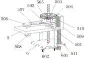
FIG. 5 is a schematic view of a drilling apparatus hoisting plate for load bearing plate production.
FIG. 6 is a schematic view of the bottom of the hoisting plate of the apparatus for producing holes for drilling in the production of load bearing panels.
FIG. 7 is a schematic view of an apparatus indexing assembly for load bearing sheet production drilling.
FIG. 8 is a schematic view of the equipment stand for drilling in the production of load bearing panels.
FIG. 9 is a schematic bottom view of the apparatus table for drilling in the production of load bearing panels.
Figure 10 is a schematic view of a loading assembly of the apparatus for producing a hole in a load bearing sheet.
Description of reference numerals:
a fixed table 1, a rubber pad 101, a side wall hinge block 102, a clamping strip 103, a bending fixture block 104, a lifting flange 105, a traction spring 106, an expanding cylinder 107, a closing disc 108, a transposition assembly 2, a torsion table 201, a positioning gear 202, a center post 203, a swing arm 204, a positioning bevel gear 205, a reduction bevel gear 206, a servo motor 207, a support plate 208, a suction disc 209, a material taking suction cup 210, an air machine 211, an elevator module 212, a feeding assembly 3, a feeding shaft seat 301, a feeding roller 302, a feeding belt 303, a grating 304, a feeding motor 305, a positioning assembly 4, a positioning table 401, a shielding plate block 402, a pressing baffle 403, a telescopic rod 404, a telescopic pipe 405, an extrusion plate block 406, a positioning spring 407, an inclined frame 408, an extrusion square sleeve 409, an extrusion table 410, a positioning cylinder 411, a bending output rod 412, a hoisting plate 5, a plane shaft seat 501, a driven wheel disc 502 and a center nut 503, the device comprises a connecting support 504, a gear ring 505, a driving wheel disc 506, a driving belt 507, a driving motor 508, a side wall support 509, a gear column 510, a fixed sleeve 511, a lifting plate 6, a movable sleeve rod 601, a driving screw 602, a movable gear 603, a rotating roller 604, a vertical drill rod 605, a triangle belt 606, an extension guide rail 7, an extension round sleeve 701, a folding plate 702, an end plate 703, a stepping motor 704, a folding screw rod 705, a movable shaft seat 706, a linkage wheel disc 707, a tension belt 708, a drilling motor 709, an open-hole drill rod 710 and a connecting bridge 8.
Detailed Description
In order to make the objects, technical solutions and advantages of the present invention more apparent, the present invention is described in further detail below with reference to the accompanying drawings and embodiments. It should be understood that the specific embodiments described herein are merely illustrative of the invention and are not intended to limit the invention.
In the description of the present invention, it is to be understood that the terms "longitudinal", "lateral", "upper", "lower", "front", "rear", "left", "right", "vertical", "horizontal", "top", "bottom", "inner", "outer", and the like, indicate orientations or positional relationships based on those shown in the drawings, are merely for convenience of description of the present invention, and do not indicate or imply that the referenced devices or elements must have a particular orientation, be constructed and operated in a particular orientation, and thus, are not to be construed as limiting the present invention.
Referring to fig. 1, 2, 3, 4, 5, 6, 7, 8, 9, and 10, the apparatus for drilling in bearing plate production includes a fixed table 1, a hoisting plate 5 is disposed above the fixed table 1, the hoisting plate 5 is fixedly connected with a building, a lifting plate 6 is disposed below the hoisting plate 5, fixed sleeves 511 are disposed on two sides of the hoisting plate 5, movable rods 601 are disposed on two sides of the lifting plate 6, the movable rods 601 are inserted into the inner sides of the fixed sleeves 511, the fixed sleeves 511 are slidably connected with the movable rods 601, a transposition assembly 2 is disposed on one side of the fixed table 1, a positioning assembly 4 is disposed on one side of the transposition assembly 2, a feeding assembly 3 is disposed on the other side of the transposition assembly 2, a rubber pad 101 is disposed in the middle of the fixed table 1, four corners of the rubber pad 101 are provided with sidewall hinge blocks 102, and a clamping strip 103 is disposed on the inner side of the sidewall hinge blocks 102, a round rod inserted into the inner side of the side wall hinge block 102 is arranged in the middle of the clamping strip 103, a bending fixture block 104 is arranged at the top end of the clamping strip 103, a rubber strip is arranged on the inner side wall of the bending fixture block 104, the bottom end of the clamping strip 103 is provided with a lifting flange 105, the lifting flange 105 is connected with the top surface of the fixed platform 1 through a traction spring 106, an expanding cylinder 107 is fixedly arranged at the bottom end of the fixed table 1, a folding disc 108 is arranged at the output end of the expanding cylinder 107, the top surface of the folding disc 108 is attached to the end of the lifting flange 105, a rubber pad 101 on the fixed table 1 is used for filling a fixed plate to be processed, after the fixed plate is placed on the rubber pad 101, then the expanding cylinder 107 releases the load, the traction spring 106 pushes the clamping strip 103 to twist through the self tension, and the bending fixture blocks 104 at the end of the clamping strip 103 can lock the four side walls of the plate, so that the automatic locking effect is realized.
The feeding assembly 3 comprises four feeding shaft seats 301, the four feeding shaft seats 301 are arranged, every two feeding shaft seats 301 form a group, a feeding roller 302 is arranged between every two feeding shaft seats 301, the feeding roller 302 is rotatably connected with the feeding shaft seats 301, the two feeding rollers 302 are connected through a feeding belt 303, a plurality of grid strips 304 are arranged on the outer side of the feeding belt 303, a feeding motor 305 is fixedly mounted on the side wall of one feeding shaft seat 301, the output end of the feeding motor 305 penetrates through the end of the feeding shaft seat 301 and the end of one feeding roller 302 and is fixedly connected with the feeding belt 303, a fixed plate to be processed is placed on the feeding belt 303 in the feeding assembly 3, and the feeding motor 305 drives the feeding belt 303 to convey the fixed plate to a designated position.
The transposition assembly 2 comprises a torsion table 201, a positioning gear 202 is arranged at the top end of the torsion table 201, an outer ring of the positioning gear 202 is fixedly connected with the top surface of the torsion table 201, a central column 203 is fixedly installed in an inner ring of the positioning gear 202, an elevator module 212 is arranged in the middle of the central column 203, a swing arm 204 is arranged at the top end of the central column 203, a suction disc 209 is arranged at the end of the swing arm 204, four material taking suction cups 210 are arranged at the bottom end of the suction disc 209, an air machine 211 is further arranged at the top end of the swing arm 204, the output end of the air machine 211 is connected with the four material taking suction cups 210 through pipelines, the pipelines between the air machine 211 and the material taking suction cups 210 are arranged on the inner side of the suction disc 209, the air machine 211 takes air in the material taking suction cups 210 out, and the material taking suction cups 210 are connected with a plate into a whole.
The outer side wall of the central column 203 is fixedly provided with a positioning bevel gear 205, one side of the positioning bevel gear 205 is provided with a speed reduction bevel gear 206, the speed reduction bevel gear 206 and the positioning bevel gear 205 are meshed with each other, the speed reduction bevel gear 206 is installed at the output end of a servo motor 207, the servo motor 207 is fixedly connected with the top surface of the torsion table 201 through a supporting plate 208, the servo motor 207 drives a swing arm 204 to be twisted above the feeding assembly 3 through a bevel gear set, and then an elevator module 212 drives the swing arm 204 to descend for a short distance to perform material taking operation.
Locating component 4 includes location platform 401, is provided with two on the lateral wall of location platform 401 and shelters from plate 402, and the bottom fixed mounting of location platform 401 has slope square frame 408, and slope square frame 408 and the lateral wall of location platform 401 form the forty-five degree contained angle, and the cover is equipped with extrusion square sleeve 409 on the slope square frame 408, and extrusion square sleeve 409 and slope square frame 408 sliding connection extrude the centre of square sleeve 409 and be provided with extrusion platform 410, location platform 401's bottom is still fixed mounting has location cylinder 411, and location cylinder 411's output is provided with the output pole 412 of buckling, buckles the end of output pole 412 and the bottom surface fixed connection of extrusion platform 410.
The top end of the extrusion table 410 is provided with a pressing baffle 403, one side of the pressing baffle 403 is provided with a telescopic rod 404, one side of the telescopic rod 404 is provided with a telescopic pipe 405, the telescopic rod 404 is connected with the telescopic pipe 405 in a sliding way, the end of the telescopic pipe 405 is provided with a squeezing plate 406, the outer sides of the telescopic rod 404 and the telescopic pipe 405 are provided with a positioning spring 407, one end of the positioning spring 407 is fixedly connected with the side wall of the pressing baffle 403, the other end of the positioning spring 407 is fixedly connected with the side wall of the squeezing plate 406, the transposition assembly 2 can place the plate on the positioning table 401, the positioning cylinder 411 at the moment drives the squeezing table 401 to move towards the positioning direction until the two squeezing plates 406 and the two shielding plates 402 are attached to the side edges of the plate, the space position of the plate is accurately positioned, then the transposition assembly 2 places the plate on the fixed table 1, and the functions of automatic feeding and automatic positioning are realized.
The top end of the hoisting plate 5 is fixedly provided with a plane shaft seat 501, the top end of the plane shaft seat 501 is provided with a driven wheel disc 502, one side of the driven wheel disc 502 is provided with a driving wheel disc 506, the driving wheel disc 506 is connected with the driven wheel disc 502 through a driving belt 507, the driving wheel disc 506 is arranged at the output end of a driving motor 508, the driving motor 508 is fixedly connected with the side wall of the hoisting plate 5, a gear ring 505 is arranged above the driven wheel disc 502, the gear ring 505 is connected with the driven wheel disc 502 through two connecting brackets 504, the middle of the driven wheel disc 502 is provided with a central nut 503, the middle of the lifting plate 6 is fixedly provided with a driving screw 602, the driving screw 602 penetrates through the plane shaft seat 501 and the central nut 503, the middle of the gear ring 505 is provided with an avoiding opening matched with the driving screw 602, and the driving motor 508 drives the driven wheel disc 502 to rotate through the driving belt 507, the nut in the middle of the driven wheel 502 drives the screw 602 to lift, and the lifting plate 6 at this time can lift relative to the hoisting plate 5.
A side wall bracket 509 is arranged at one side of the hoisting plate 5, a gear column 510 is arranged at the top end of the side wall bracket 509, the gear column 510 and a gear ring 505 are engaged with each other, through holes matched with the gear column 510 are arranged on the hoisting plate 5 and the lifting plate 6, a movable gear 603 is arranged at the bottom surface of the lifting plate 6, the movable gear 603 is rotatably connected with the bottom surface of the lifting plate 6, the movable gear 603 is engaged with the gear column 510, three rotating rollers 604 are further arranged at the bottom end of the lifting plate 6, one of the rotating rollers 604 is fixedly arranged with the movable gear 603, the rotating rollers 604 are connected through a triangular belt 606, vertical drill rods 605 are arranged at the bottom ends of the three rotating rollers 604, the gear ring 505 rotates while the lifting plate 6 moves, the gear ring 55 drives the gear column 510 to rotate, the gear column 510 drives the movable gear 603 to rotate, and the height of the gear column 510 is unchanged, at this moment, the movable gear 603 goes up and down and still keeps a meshed state with the gear column 510, and at this moment, the three rotating rollers 604 and the vertical drill rod 605 move downwards to open holes in the fixed plate, so that the automatic processing effect is realized, and power source equipment is saved.
Two extension guide rails 7 are fixedly installed on one side of the fixed table 1, an end plate 703 is arranged at the end of each extension guide rail 7, an extension round sleeve 701 is sleeved on each extension guide rail 7, the extension round sleeve 701 is connected with the extension guide rails 7 in a sliding mode, a folding plate 702 is arranged in the middle of the extension round sleeve 701, a stepping motor 704 is fixedly installed on the side wall of each end plate 703, a folding screw rod 705 is installed at the output end of the stepping motor 704, the folding screw rod 705 penetrates through the folding plate 702, a nut block matched with the folding screw rod 705 is arranged in the middle of the folding plate 702, and the stepping motor 704 drives the folding plate 702 to move towards the fixed table 1 through the folding screw rod 705.
The top end of the folding plate 702 is provided with three movable shaft seats 706, one side of each movable shaft seat 706 is provided with a linkage wheel disc 707, the linkage wheel discs 707 are respectively connected with the movable shaft seats 706 in a rotating way, the diameters of the three linkage wheel discs 707 are different, the diameter of the middle linkage wheel disc 707 is larger than the diameters of the linkage wheel discs 707 at the two sides, the three linkage wheel discs 707 are connected through a tension belt 708, an open-hole drill rod 710 is fixedly arranged on the side wall of the linkage wheel disc 707, a drilling motor 709 is fixedly mounted on the side wall of one movable shaft seat 706, the output end of the drilling motor 709 penetrates through the movable shaft seat 706 and is fixedly connected with the side wall of one linkage wheel disc 707, the drilling motor 709 at the moment drives the three linkage wheel discs 707 to rotate simultaneously, the linkage wheel disc 707 pushes towards the side wall of the fixed plate 1 in the running process, three small holes can be formed in the side wall of the plate, and the effect of automatically processing the side wall is achieved.
The equipment working steps are as follows: a fixed plate to be processed is placed on a feeding belt 303 in a feeding assembly 3, a feeding motor 305 drives the feeding belt 303 to convey the fixed plate to a designated position, a servo motor 207 drives a swing arm 204 to be twisted above the feeding assembly 3 through a bevel gear set, then a lifter module 212 drives the swing arm 204 to descend for a short distance, an air machine 211 extracts air in a material taking suction cup 210, the material taking suction cup 210 is connected with the plate into a whole, a transposition assembly 2 can place the plate on a positioning table 401, a positioning air cylinder 411 drives an extrusion table 401 to move towards positioning until two extrusion plates 406 and two shielding plates 402 are attached to the side edges of the plate, the space position of the plate is accurately positioned, the functions of automatic feeding and automatic positioning are achieved, then the transposition assembly 2 places the plate on the fixing table 1, a rubber pad 101 on the fixing table 1 is used for filling the fixed plate to be processed, after a fixed plate is placed on the rubber pad 101, the expansion cylinder 107 releases the load, the traction spring 106 pushes the clamping strip 103 to twist by self tension, the bending fixture block 104 at the end of the clamping strip 103 locks four side walls of the plate, the driving motor 508 drives the driven wheel disc 502 to rotate through the driving belt 507, the nut in the middle of the driven wheel disc 502 drives the screw 602 to lift, the lifting plate 6 can lift relative to the hoisting plate 5 at the moment, the gear ring 505 rotates while the lifting plate 6 moves, the gear ring 55 drives the gear column 510 to rotate, the gear column 510 drives the movable gear 603 to rotate, the height of the gear column 510 is unchanged, the movable gear 603 still keeps a meshed state with the gear column 510 when lifting, at the moment, the three rotating rollers 604 and the vertical drill rod 605 move downwards to open holes in the fixed plate, the automatic processing effect is realized, and power source equipment is saved, the stepping motor 704 drives the folding plate 702 to move towards the fixed table 1 through the folding screw 705, the drilling motor 709 at the moment drives the three linkage wheel discs 707 to rotate simultaneously, the linkage wheel discs 707 are pushed towards the side wall of the fixed plate 1 in the operation process, three small holes can be formed in the side wall of the plate, and the effect of automatically processing the side wall is achieved.
The above description is only a preferred embodiment of the present invention, and is not intended to limit the technical scope of the present invention, so that any minor modifications, equivalent changes and modifications made to the above embodiment according to the technical spirit of the present invention are within the technical scope of the present invention.
Claims (10)
1. The utility model provides a drilling equipment is used in production of bearing plate which characterized in that: comprises a fixed table (1), a hoisting plate (5) is arranged above the fixed table (1), the hoisting plate (5) is fixedly connected with a building, a lifting plate (6) is arranged below the hoisting plate (5), two sides of the hoisting plate (5) are provided with fixed sleeves (511), two sides of the lifting plate (6) are provided with movable sleeve rods (601), the movable sleeve rods (601) are inserted into the inner sides of the fixed sleeves (511), the fixed sleeves (511) are slidably connected with the movable sleeve rods (601), one side of the fixed table (1) is provided with a transposition assembly (2), one side of the transposition assembly (2) is provided with a positioning assembly (4), the other side of the transposition assembly (2) is provided with a feeding assembly (3), the middle of the fixed table (1) is provided with a rubber pad (101), and four corners of the rubber pad (101) are provided with side wall hinge blocks (102), the inner side of the side wall hinging block (102) is provided with a clamping strip (103), a round rod penetrating into the inner side of the side wall hinging block (102) is arranged in the middle of the clamping strip (103), a bending clamping block (104) is arranged at the top end of the clamping strip (103), a rubber strip is arranged on the inner side wall of the bending clamping block (104), a lifting flange (105) is arranged at the bottom end of the clamping strip (103), the lifting flange (105) is connected with the top surface of the fixed table (1) through a traction spring (106), an expansion cylinder (107) is fixedly arranged at the bottom end of the fixed table (1), an output end of the expansion cylinder (107) is provided with a folding disc (108), and the top surface of the folding disc (108) is attached to the end of the lifting flange (105).
2. The apparatus for producing a hole in a load-bearing plate according to claim 1, wherein: the feeding assembly (3) comprises four feeding shaft seats (301), the four feeding shaft seats (301) are arranged, every two feeding shaft seats (301) form a group, a feeding roller (302) is arranged between every two feeding shaft seats (301), the feeding roller (302) is rotatably connected with the feeding shaft seats (301), the two feeding rollers (302) are connected through a feeding belt (303), the outer side of the feeding belt (303) is provided with a plurality of grid bars (304), a feeding motor (305) is fixedly mounted on the side wall of one feeding shaft seat (301), and the output end of the feeding motor (305) penetrates through the end fixed connection of the feeding shaft seats (301) and the end fixed connection of one feeding roller (302).
3. The apparatus for producing a hole in a load-bearing plate according to claim 1, wherein: the transposition assembly (2) comprises a torsion table (201), a positioning gear (202) is arranged at the top end of the torsion table (201), an outer ring of the positioning gear (202) is fixedly connected with the top surface of the torsion table (201), a center column (203) is fixedly installed in an inner ring of the positioning gear (202), an elevator module (212) is arranged in the middle of the center column (203), a swing arm (204) is arranged at the top end of the center column (203), a suction disc (209) is arranged at the end of the swing arm (204), four material taking suction cups (210) are arranged at the bottom end of the suction disc (209), an air machine (211) is further arranged at the top end of the swing arm (204), the output end of the air machine (211) is connected with the four material taking suction cups (210) through a pipeline, and the pipeline between the air machine (211) and the material taking suction cups (210) is arranged on the inner side of the suction disc (209).
4. The apparatus for producing a hole in a load-bearing plate according to claim 3, wherein: the outer side wall of the central column (203) is fixedly provided with a positioning bevel gear (205), one side of the positioning bevel gear (205) is provided with a speed reduction bevel gear (206), the speed reduction bevel gear (206) is meshed with the positioning bevel gear (205), the speed reduction bevel gear (206) is arranged at the output end of a servo motor (207), and the servo motor (207) is fixedly connected with the top surface of the torsion table (201) through a supporting plate (208).
5. The apparatus for producing a hole in a load-bearing plate according to claim 1, wherein: locating component (4) are including location platform (401), are provided with two on the lateral wall of location platform (401) and shelter from plate (402), and the bottom fixed mounting of location platform (401) has slope square frame (408), and the lateral wall of slope square frame (408) and location platform (401) forms forty-five degree contained angles, and the cover is equipped with extrusion square cover (409) on slope square frame (408), and extrusion square cover (409) and slope square frame (408) sliding connection, the centre of extrusion square cover (409) is provided with extrusion platform (410), the bottom of location platform (401) is fixed mounting still has location cylinder (411), and the output of location cylinder (411) is provided with bending output pole (412), bending output pole (412) the bottom surface and the fixed connection of extrusion platform (410).
6. The apparatus for producing a hole in a load-bearing plate according to claim 5, wherein: the pressing baffle (403) is arranged at the top end of the extrusion table (410), the telescopic rod (404) is arranged on one side of the pressing baffle (403), the telescopic pipe (405) is arranged on one side of the telescopic rod (404), the telescopic rod (404) is in sliding connection with the telescopic pipe (405), the extrusion plate block (406) is arranged at the end of the telescopic pipe (405), the positioning springs (407) are arranged on the outer sides of the telescopic rod (404) and the telescopic pipe (405), one ends of the positioning springs (407) are fixedly connected with the side wall of the pressing baffle (403), and the other ends of the positioning springs (407) are fixedly connected with the side wall of the extrusion plate block (406).
7. The apparatus for producing a hole in a load-bearing plate according to claim 1, wherein: the lifting plate is characterized in that a plane shaft seat (501) is fixedly mounted at the top end of the lifting plate (5), a driven wheel disc (502) is arranged at the top end of the plane shaft seat (501), a driving wheel disc (506) is mounted on one side of the driven wheel disc (502), the driving wheel disc (506) is connected with the driven wheel disc (502) through a driving belt (507), the driving wheel disc (506) is mounted at the output end of a driving motor (508), the driving motor (508) is fixedly connected with the side wall of the lifting plate (5), a gear ring (505) is arranged above the driven wheel disc (502), the gear ring (505) is connected with the driven wheel disc (502) through two connecting supports (504), a center nut (503) is arranged in the middle of the driven wheel disc (502), a driving screw (602) is fixedly mounted in the middle of the lifting plate (6), and the driving screw (602) passes through the plane shaft seat (501) and the center nut (503), an avoiding opening matched with the driving screw rod (602) is arranged in the middle of the gear ring (505).
8. The apparatus for producing a hole in a load-bearing plate according to claim 1, wherein: one side of hoist and mount board (5) is provided with lateral wall support (509), and the top of lateral wall support (509) is provided with gear post (510), gear post (510) and gear ring (505) intermeshing, all be provided with on hoist and mount board (5) and lifter plate (6) with gear post (510) assorted opening, the bottom surface of lifter plate (6) is provided with one loose gear (603), the bottom surface swivelling joint of loose gear (603) and lifter plate (6), loose gear (603) and gear post (510) intermeshing, the bottom of lifter plate (6) still is provided with three rotatory gyro wheel (604), and one of them rotatory gyro wheel (604) and loose gear (603) fixed mounting connect through triangle belt (606) between rotatory gyro wheel (604), and the bottom of three rotatory gyro wheel (604) all is provided with vertical drilling rod (605).
9. The apparatus for producing a hole in a load-bearing plate according to claim 1, wherein: one side fixed mounting of fixed station (1) has two extension guide rail (7), and the end trip of extension guide rail (7) is provided with end plate (703), the cover is equipped with extension circle cover (701) on extension guide rail (7), extends circle cover (701) and extension guide rail (7) sliding connection, the centre of extending circle cover (701) is provided with folds board (702), and fixed mounting has step motor (704) on the lateral wall of end plate (703), and fold lead screw (705) are installed to the output of step motor (704), folds lead screw (705) and wear from folding board (702), folds the centre of board (702) and is provided with and folds lead screw (705) assorted nut piece.
10. The apparatus for producing a hole in a load-bearing plate according to claim 9, wherein: the top of folding board (702) is provided with three movable shaft seat (706), and one side of movable shaft seat (706) all is provided with linkage rim plate (707), and linkage rim plate (707) respectively with movable shaft seat (706) swivelling joint, and the diameter diverse of three linkage rim plate (707), the diameter of middle linkage rim plate (707) is greater than the diameter of both sides linkage rim plate (707), connects through tension belt (708) between three linkage rim plate (707), fixed mounting has trompil drilling rod (710) on the lateral wall of linkage rim plate (707), and fixed mounting has drilling motor (709) on the lateral wall of one of them movable shaft seat (706), and the output of drilling motor (709) passes the lateral wall fixed connection of movable shaft seat (706) and one of them linkage rim plate (707).
Priority Applications (1)
| Application Number | Priority Date | Filing Date | Title |
|---|---|---|---|
| CN202110792884.9A CN113245592B (en) | 2021-07-14 | 2021-07-14 | Equipment for producing and drilling bearing plate |
Applications Claiming Priority (1)
| Application Number | Priority Date | Filing Date | Title |
|---|---|---|---|
| CN202110792884.9A CN113245592B (en) | 2021-07-14 | 2021-07-14 | Equipment for producing and drilling bearing plate |
Publications (2)
| Publication Number | Publication Date |
|---|---|
| CN113245592A CN113245592A (en) | 2021-08-13 |
| CN113245592B true CN113245592B (en) | 2021-09-10 |
Family
ID=77191321
Family Applications (1)
| Application Number | Title | Priority Date | Filing Date |
|---|---|---|---|
| CN202110792884.9A Active CN113245592B (en) | 2021-07-14 | 2021-07-14 | Equipment for producing and drilling bearing plate |
Country Status (1)
| Country | Link |
|---|---|
| CN (1) | CN113245592B (en) |
Families Citing this family (5)
| Publication number | Priority date | Publication date | Assignee | Title |
|---|---|---|---|---|
| CN115609373A (en) * | 2021-09-06 | 2023-01-17 | 宜兴市永昌轧辊有限公司 | Laser cladding synchronous grinding process for roller repair |
| CN113649843A (en) * | 2021-09-22 | 2021-11-16 | 广东昊胜智能设备有限公司 | A Synchronous Translation Pneumatic Positioning Mechanism |
| CN114393432B (en) * | 2022-03-07 | 2023-05-05 | 湖南飞桥汽车板簧有限公司 | Clamping device for machining automobile leaf springs |
| CN114683056B (en) * | 2022-04-14 | 2023-01-24 | 中科天工电气控股有限公司 | Automatic processing equipment is used in production of low voltage distribution box |
| CN116175126B (en) * | 2023-02-23 | 2024-08-30 | 湖南省新化县鑫星电子陶瓷有限责任公司 | Vacuum ceramic connecting piece needle tube sealing detection device |
Citations (12)
| Publication number | Priority date | Publication date | Assignee | Title |
|---|---|---|---|---|
| JP2005286243A (en) * | 2004-03-30 | 2005-10-13 | Miyota Kk | Automatically packaging method using forming tray |
| CN202985936U (en) * | 2013-01-04 | 2013-06-12 | 何杰 | Automatic feeding positioning table for injection moulding separator of refrigerator |
| CN104400647A (en) * | 2014-12-07 | 2015-03-11 | 绥阳县耐环铝业有限公司 | Clamping fixture for aluminum cabinet during polishing |
| JP2016034662A (en) * | 2014-08-05 | 2016-03-17 | 株式会社アマダホールディングス | Method for positioning and moving plate workpiece and plate workpiece processing apparatus |
| CN106736674A (en) * | 2016-11-30 | 2017-05-31 | 无锡凯涵科技有限公司 | The boring grab of adaptor |
| CN206475271U (en) * | 2016-12-29 | 2017-09-08 | 天津市亚星家具有限公司 | A kind of Furniture panel rig |
| CN206854860U (en) * | 2017-05-31 | 2018-01-09 | 昆山久茂电子科技有限公司 | It is a kind of can accurate transformation station radium-shine tool |
| CN107717460A (en) * | 2017-11-16 | 2018-02-23 | 浙江工业大学奉化智慧经济研究院 | A kind of automatic processing device of bearing inner race screw |
| CN108908390A (en) * | 2018-07-13 | 2018-11-30 | 哈尔滨工业大学(深圳) | A kind of the clamping jaw clamping device and its robot of co-operating |
| CN208712904U (en) * | 2018-09-14 | 2019-04-09 | 扬州大学 | An automatic and efficient three-jaw chuck based on a tapered shaft |
| CN209717087U (en) * | 2018-11-16 | 2019-12-03 | 济南威成汽车零部件有限公司 | A kind of hydraumatic chucking device |
| CN211606951U (en) * | 2020-04-10 | 2020-09-29 | 安徽亚芯微科技有限公司 | Flexible line way board paster processing tool |
-
2021
- 2021-07-14 CN CN202110792884.9A patent/CN113245592B/en active Active
Patent Citations (12)
| Publication number | Priority date | Publication date | Assignee | Title |
|---|---|---|---|---|
| JP2005286243A (en) * | 2004-03-30 | 2005-10-13 | Miyota Kk | Automatically packaging method using forming tray |
| CN202985936U (en) * | 2013-01-04 | 2013-06-12 | 何杰 | Automatic feeding positioning table for injection moulding separator of refrigerator |
| JP2016034662A (en) * | 2014-08-05 | 2016-03-17 | 株式会社アマダホールディングス | Method for positioning and moving plate workpiece and plate workpiece processing apparatus |
| CN104400647A (en) * | 2014-12-07 | 2015-03-11 | 绥阳县耐环铝业有限公司 | Clamping fixture for aluminum cabinet during polishing |
| CN106736674A (en) * | 2016-11-30 | 2017-05-31 | 无锡凯涵科技有限公司 | The boring grab of adaptor |
| CN206475271U (en) * | 2016-12-29 | 2017-09-08 | 天津市亚星家具有限公司 | A kind of Furniture panel rig |
| CN206854860U (en) * | 2017-05-31 | 2018-01-09 | 昆山久茂电子科技有限公司 | It is a kind of can accurate transformation station radium-shine tool |
| CN107717460A (en) * | 2017-11-16 | 2018-02-23 | 浙江工业大学奉化智慧经济研究院 | A kind of automatic processing device of bearing inner race screw |
| CN108908390A (en) * | 2018-07-13 | 2018-11-30 | 哈尔滨工业大学(深圳) | A kind of the clamping jaw clamping device and its robot of co-operating |
| CN208712904U (en) * | 2018-09-14 | 2019-04-09 | 扬州大学 | An automatic and efficient three-jaw chuck based on a tapered shaft |
| CN209717087U (en) * | 2018-11-16 | 2019-12-03 | 济南威成汽车零部件有限公司 | A kind of hydraumatic chucking device |
| CN211606951U (en) * | 2020-04-10 | 2020-09-29 | 安徽亚芯微科技有限公司 | Flexible line way board paster processing tool |
Also Published As
| Publication number | Publication date |
|---|---|
| CN113245592A (en) | 2021-08-13 |
Similar Documents
| Publication | Publication Date | Title |
|---|---|---|
| CN113245592B (en) | Equipment for producing and drilling bearing plate | |
| CN210854325U (en) | Panel upset feeding equipment | |
| CN113084578A (en) | Stamping structure for automobile chassis | |
| CN113263412B (en) | Machine tool equipment for polishing bearing square blocks | |
| CN112496397B (en) | Installation mechanism of plate body component in power distribution cabinet | |
| CN112536511B (en) | Steel constructs device of assembling in advance | |
| CN211077669U (en) | Automatic three-axis glass feeding mechanism and system | |
| CN212635671U (en) | Positioner for assembly | |
| CN111646359B (en) | Concrete feeding equipment for building construction and method thereof | |
| CN110980515A (en) | Multi-angle heavy object promotes portal frame | |
| CN116674943A (en) | Multi-station line quality inspection production line | |
| CN220841356U (en) | A supplementary loading attachment of raw materials for adhesive tape production | |
| CN112239078A (en) | Square steel carrying system and method based on double-truss robot cooperation | |
| CN216736471U (en) | Alloy door and window transfer system | |
| CN220536721U (en) | Multi-station line quality inspection production line | |
| CN212769605U (en) | Laminar flow car elevating system | |
| CN214323240U (en) | Automobile front seat framework torsion spring assembling device | |
| CN221159107U (en) | Industrial automatic welding robot moves and carries device | |
| CN214653327U (en) | Space cam lifting mechanism | |
| CN222006566U (en) | Loading and unloading device for laser cutting plates | |
| CN218426871U (en) | Intersecting line cutting machine | |
| CN217497550U (en) | Transfer device of body of tower among air separation fractionating tower equipment | |
| CN219384002U (en) | Automatic net piece feeding device | |
| CN215754949U (en) | Vehicle license plate conveying unit and vehicle license plate conveying device | |
| CN221939483U (en) | Automatic wood strip loading machine |
Legal Events
| Date | Code | Title | Description |
|---|---|---|---|
| PB01 | Publication | ||
| PB01 | Publication | ||
| SE01 | Entry into force of request for substantive examination | ||
| SE01 | Entry into force of request for substantive examination | ||
| GR01 | Patent grant | ||
| GR01 | Patent grant |