CN113226713B - Additive manufacturing system, method and medium for producing three-dimensional objects - Google Patents
Additive manufacturing system, method and medium for producing three-dimensional objects Download PDFInfo
- Publication number
- CN113226713B CN113226713B CN201980086462.0A CN201980086462A CN113226713B CN 113226713 B CN113226713 B CN 113226713B CN 201980086462 A CN201980086462 A CN 201980086462A CN 113226713 B CN113226713 B CN 113226713B
- Authority
- CN
- China
- Prior art keywords
- build material
- component
- build
- receiving area
- reagent
- Prior art date
- Legal status (The legal status is an assumption and is not a legal conclusion. Google has not performed a legal analysis and makes no representation as to the accuracy of the status listed.)
- Expired - Fee Related
Links
Images


Classifications
-
- B—PERFORMING OPERATIONS; TRANSPORTING
- B29—WORKING OF PLASTICS; WORKING OF SUBSTANCES IN A PLASTIC STATE IN GENERAL
- B29C—SHAPING OR JOINING OF PLASTICS; SHAPING OF MATERIAL IN A PLASTIC STATE, NOT OTHERWISE PROVIDED FOR; AFTER-TREATMENT OF THE SHAPED PRODUCTS, e.g. REPAIRING
- B29C64/00—Additive manufacturing, i.e. manufacturing of three-dimensional [3D] objects by additive deposition, additive agglomeration or additive layering, e.g. by 3D printing, stereolithography or selective laser sintering
- B29C64/10—Processes of additive manufacturing
- B29C64/188—Processes of additive manufacturing involving additional operations performed on the added layers, e.g. smoothing, grinding or thickness control
-
- B—PERFORMING OPERATIONS; TRANSPORTING
- B29—WORKING OF PLASTICS; WORKING OF SUBSTANCES IN A PLASTIC STATE IN GENERAL
- B29C—SHAPING OR JOINING OF PLASTICS; SHAPING OF MATERIAL IN A PLASTIC STATE, NOT OTHERWISE PROVIDED FOR; AFTER-TREATMENT OF THE SHAPED PRODUCTS, e.g. REPAIRING
- B29C64/00—Additive manufacturing, i.e. manufacturing of three-dimensional [3D] objects by additive deposition, additive agglomeration or additive layering, e.g. by 3D printing, stereolithography or selective laser sintering
- B29C64/10—Processes of additive manufacturing
- B29C64/165—Processes of additive manufacturing using a combination of solid and fluid materials, e.g. a powder selectively bound by a liquid binder, catalyst, inhibitor or energy absorber
-
- B—PERFORMING OPERATIONS; TRANSPORTING
- B29—WORKING OF PLASTICS; WORKING OF SUBSTANCES IN A PLASTIC STATE IN GENERAL
- B29C—SHAPING OR JOINING OF PLASTICS; SHAPING OF MATERIAL IN A PLASTIC STATE, NOT OTHERWISE PROVIDED FOR; AFTER-TREATMENT OF THE SHAPED PRODUCTS, e.g. REPAIRING
- B29C64/00—Additive manufacturing, i.e. manufacturing of three-dimensional [3D] objects by additive deposition, additive agglomeration or additive layering, e.g. by 3D printing, stereolithography or selective laser sintering
- B29C64/20—Apparatus for additive manufacturing; Details thereof or accessories therefor
- B29C64/205—Means for applying layers
- B29C64/209—Heads; Nozzles
-
- B—PERFORMING OPERATIONS; TRANSPORTING
- B29—WORKING OF PLASTICS; WORKING OF SUBSTANCES IN A PLASTIC STATE IN GENERAL
- B29C—SHAPING OR JOINING OF PLASTICS; SHAPING OF MATERIAL IN A PLASTIC STATE, NOT OTHERWISE PROVIDED FOR; AFTER-TREATMENT OF THE SHAPED PRODUCTS, e.g. REPAIRING
- B29C64/00—Additive manufacturing, i.e. manufacturing of three-dimensional [3D] objects by additive deposition, additive agglomeration or additive layering, e.g. by 3D printing, stereolithography or selective laser sintering
- B29C64/20—Apparatus for additive manufacturing; Details thereof or accessories therefor
- B29C64/264—Arrangements for irradiation
-
- B—PERFORMING OPERATIONS; TRANSPORTING
- B29—WORKING OF PLASTICS; WORKING OF SUBSTANCES IN A PLASTIC STATE IN GENERAL
- B29C—SHAPING OR JOINING OF PLASTICS; SHAPING OF MATERIAL IN A PLASTIC STATE, NOT OTHERWISE PROVIDED FOR; AFTER-TREATMENT OF THE SHAPED PRODUCTS, e.g. REPAIRING
- B29C64/00—Additive manufacturing, i.e. manufacturing of three-dimensional [3D] objects by additive deposition, additive agglomeration or additive layering, e.g. by 3D printing, stereolithography or selective laser sintering
- B29C64/30—Auxiliary operations or equipment
- B29C64/386—Data acquisition or data processing for additive manufacturing
- B29C64/393—Data acquisition or data processing for additive manufacturing for controlling or regulating additive manufacturing processes
-
- B—PERFORMING OPERATIONS; TRANSPORTING
- B33—ADDITIVE MANUFACTURING TECHNOLOGY
- B33Y—ADDITIVE MANUFACTURING, i.e. MANUFACTURING OF THREE-DIMENSIONAL [3-D] OBJECTS BY ADDITIVE DEPOSITION, ADDITIVE AGGLOMERATION OR ADDITIVE LAYERING, e.g. BY 3-D PRINTING, STEREOLITHOGRAPHY OR SELECTIVE LASER SINTERING
- B33Y10/00—Processes of additive manufacturing
-
- B—PERFORMING OPERATIONS; TRANSPORTING
- B33—ADDITIVE MANUFACTURING TECHNOLOGY
- B33Y—ADDITIVE MANUFACTURING, i.e. MANUFACTURING OF THREE-DIMENSIONAL [3-D] OBJECTS BY ADDITIVE DEPOSITION, ADDITIVE AGGLOMERATION OR ADDITIVE LAYERING, e.g. BY 3-D PRINTING, STEREOLITHOGRAPHY OR SELECTIVE LASER SINTERING
- B33Y30/00—Apparatus for additive manufacturing; Details thereof or accessories therefor
-
- B—PERFORMING OPERATIONS; TRANSPORTING
- B33—ADDITIVE MANUFACTURING TECHNOLOGY
- B33Y—ADDITIVE MANUFACTURING, i.e. MANUFACTURING OF THREE-DIMENSIONAL [3-D] OBJECTS BY ADDITIVE DEPOSITION, ADDITIVE AGGLOMERATION OR ADDITIVE LAYERING, e.g. BY 3-D PRINTING, STEREOLITHOGRAPHY OR SELECTIVE LASER SINTERING
- B33Y50/00—Data acquisition or data processing for additive manufacturing
- B33Y50/02—Data acquisition or data processing for additive manufacturing for controlling or regulating additive manufacturing processes
-
- B—PERFORMING OPERATIONS; TRANSPORTING
- B29—WORKING OF PLASTICS; WORKING OF SUBSTANCES IN A PLASTIC STATE IN GENERAL
- B29L—INDEXING SCHEME ASSOCIATED WITH SUBCLASS B29C, RELATING TO PARTICULAR ARTICLES
- B29L2031/00—Other particular articles
- B29L2031/34—Electrical apparatus, e.g. sparking plugs or parts thereof
-
- B—PERFORMING OPERATIONS; TRANSPORTING
- B33—ADDITIVE MANUFACTURING TECHNOLOGY
- B33Y—ADDITIVE MANUFACTURING, i.e. MANUFACTURING OF THREE-DIMENSIONAL [3-D] OBJECTS BY ADDITIVE DEPOSITION, ADDITIVE AGGLOMERATION OR ADDITIVE LAYERING, e.g. BY 3-D PRINTING, STEREOLITHOGRAPHY OR SELECTIVE LASER SINTERING
- B33Y50/00—Data acquisition or data processing for additive manufacturing
Landscapes
- Chemical & Material Sciences (AREA)
- Engineering & Computer Science (AREA)
- Materials Engineering (AREA)
- Manufacturing & Machinery (AREA)
- Physics & Mathematics (AREA)
- Mechanical Engineering (AREA)
- Optics & Photonics (AREA)
- Health & Medical Sciences (AREA)
- Toxicology (AREA)
Abstract
一些示例包括增材制造系统,该增材制造系统包括处理器和用于存储指令的存储器。指令使处理器根据所接收的与三维构建物体相关的数据生成打印数据。所生成的打印数据包括:用于在构建材料层的构建区域处分配第一试剂的所定义的打印数据;用于在该构建材料层的构建区域内的部件接纳区域处选择性地分配第二试剂的所定义的打印数据,该第二试剂用于将该部件接纳区域处的构建材料的粘度局部降低至粘性状态;以及用于在该部件接纳区域正处于粘性状态时将部件定位在该部件接纳区域内的所定义的打印数据。
Some examples include an additive manufacturing system that includes a processor and memory for storing instructions. The instructions cause the processor to generate print data based on the received data related to the three-dimensionally constructed object. The generated print data includes: defined print data for dispensing a first reagent at a build area of the build material layer; defined print data of a reagent for locally reducing the viscosity of the build material at the part-receiving area to a viscous state; and for positioning the part on the part while the part-receiving area is in the viscous state Accepts the defined print data within the area.
Description
技术领域technical field
本公开涉及增材制造系统、用于产生三维物体的方法和介质。The present disclosure relates to additive manufacturing systems, methods and media for producing three-dimensional objects.
背景技术Background technique
增材制造机器通过构建多个材料层来产生三维(3D)物体。一些3D打印技术被认为是增材工艺,因为它们涉及施加连续的材料层。一些增材制造机器常被称为“3D打印机”。3D打印机和其他增材制造机器使得可以将物体的其他数字表示的CAD(计算机辅助设计)模型转换成物理物体。Additive manufacturing machines produce three-dimensional (3D) objects by building multiple layers of material. Some 3D printing techniques are considered additive processes because they involve applying successive layers of material. Some additive manufacturing machines are often referred to as "3D printers". 3D printers and other additive manufacturing machines make it possible to convert otherwise digitally represented CAD (computer-aided design) models of objects into physical objects.
发明内容Contents of the invention
一种增材制造系统,包括:处理器;以及存储器,所述存储器用于存储指令,所述指令用于使所述处理器进行以下操作:根据所接收的与三维构建物体相关的数据生成打印数据,所生成的打印数据包括:用于在构建材料层的构建区域处分配第一试剂的所定义的打印数据,用于在所述构建材料层的所述构建区域内的部件接纳区域处分配第二试剂的所定义的打印数据,所述第二试剂用于将所述部件接纳区域处的所述构建材料的粘度局部降低至粘性状态,以及用于在所述部件接纳区域正处于所述粘性状态时将部件定位在所述部件接纳区域内的所定义的打印数据。An additive manufacturing system comprising: a processor; and a memory for storing instructions for causing the processor to: generate a print based on received data related to a three-dimensionally constructed object data, the generated print data comprising: defined print data for dispensing a first reagent at a build area of a build material layer for dispensing at a component receiving area within said build area of said build material layer Defined print data for a second reagent for locally reducing the viscosity of the build material at the part receiving area to a viscous state, and for the part receiving area being in the Defined print data that positions the part within the part receiving area in the sticky state.
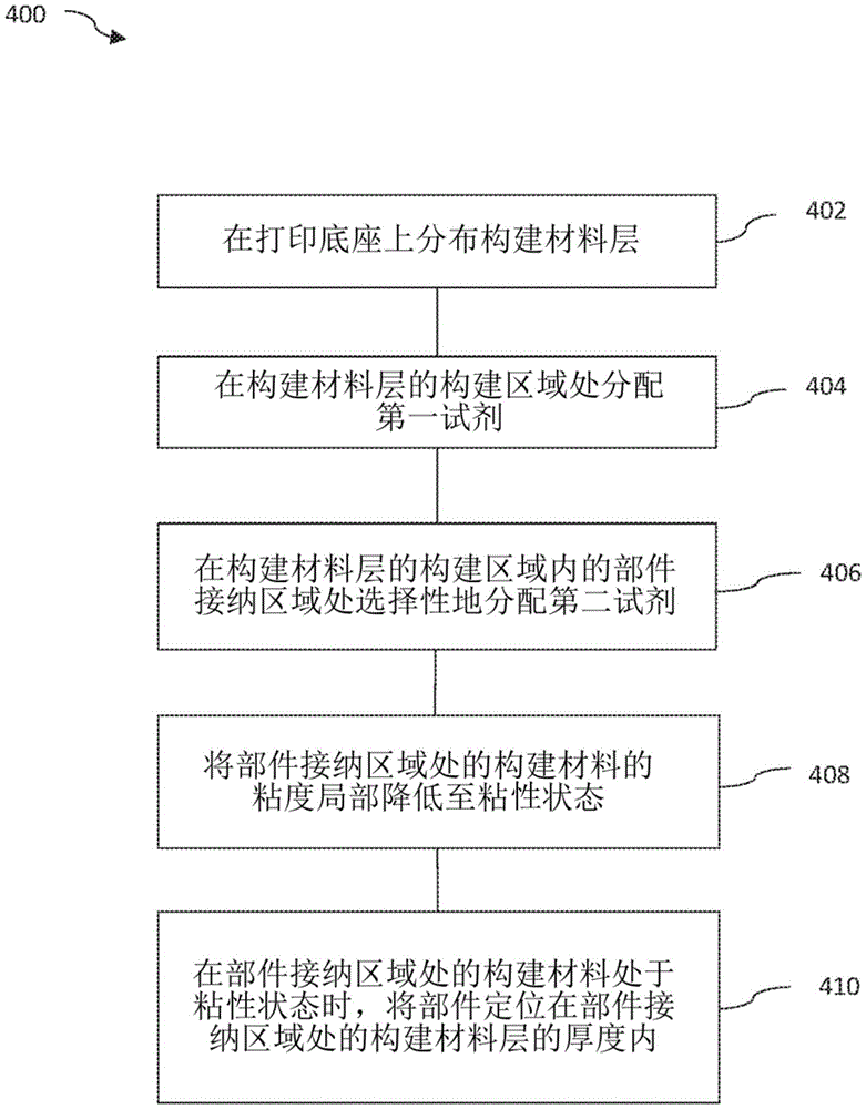
一种用于产生三维物体的方法,包括:将构建材料层分布在打印底座上;在所述构建材料层的构建区域处分配第一试剂;在所述构建材料层的所述构建区域内的部件接纳区域处选择性地分配第二试剂;将所述部件接纳区域处的所述构建材料的粘度局部降低至粘性状态;以及在所述部件接纳区域处的所述构建材料处于所述粘性状态时,在所述部件接纳区域处将部件定位在所述构建材料层的厚度内。A method for producing a three-dimensional object comprising: distributing a layer of build material on a printing bed; dispensing a first reagent at a build area of the layer of build material; selectively dispensing a second reagent at a component receiving area; locally reducing the viscosity of the build material at the component receiving area to a viscous state; and the build material at the component receiving area in the viscous state , positioning a component within the thickness of the layer of build material at the component receiving area.
一种存储有指令的非暂态计算机可读数据存储介质,所述指令可由处理器执行以进行以下操作:定义用于在多个构建材料层的构建区域处分配第一试剂的打印数据;定义用于在所述构建区域内的部件接纳区域处选择性地分配第二试剂的打印数据,所述第二试剂用于将所述部件接纳区域处的构建材料的粘度局部降低至粘性状态;以及定义用于在所述部件接纳区域正处于粘性状态时将部件定位在所述部件接纳区域内的打印数据。A non-transitory computer readable data storage medium storing instructions executable by a processor to: define print data for dispensing a first reagent at a build area of a plurality of build material layers; define print data for selectively dispensing at a part receiving area within the build area a second agent for locally reducing the viscosity of the build material at the part receiving area to a viscous state; and Print data is defined for positioning a component within the component receiving area while the component receiving area is in an adhesive state.
附图说明Description of drawings
图1是根据本公开的方面的示例增材制造系统的框图。FIG. 1 is a block diagram of an example additive manufacturing system according to aspects of the present disclosure.
图2是根据本公开的方面的示例增材制造系统的示意图。2 is a schematic diagram of an example additive manufacturing system according to aspects of the present disclosure.
图3A至图3C是根据本公开的方面的包括设置在部件接纳区域内的部件的三维构建物体的示意性截面侧视图。3A-3C are schematic cross-sectional side views of a three-dimensional built object including components disposed within a component receiving area according to aspects of the present disclosure.
图3D是根据本公开的方面的包括设置在部件接纳区域内的部件的三维构建物体的示意性截面顶视图。3D is a schematic cross-sectional top view of a three-dimensional built object including components disposed within a component receiving area according to aspects of the present disclosure.
图4是根据本公开的方面的示例增材制造方法的流程图。4 is a flowchart of an example additive manufacturing method according to aspects of the present disclosure.
图5是根据本公开的方面的包括可由处理器执行的一组指令的示例非暂态计算机可读介质的框图。5 is a block diagram of an example non-transitory computer-readable medium including a set of instructions executable by a processor according to aspects of the present disclosure.
具体实施方式Detailed ways
在以下具体实施方式中,对附图进行了参考,这些附图形成具体实施方式的一部分,并且在附图中通过说明的方式示出了可以实践本公开的具体示例。应当理解的是,在不脱离本公开的范围的情况下,可以利用其他示例并且可以做出结构或逻辑变化。因此以下具体实施方式不应当被理解为限制性的意义,并且本公开的范围由所附权利要求限定。应当理解的是,除非另外特别指出,否则本文所描述的各种示例的特征可以部分地或全部地彼此组合。In the following Detailed Description, reference is made to the accompanying drawings, which form a part hereof, and in which are shown by way of illustration specific examples in which the disclosure may be practiced. It is to be understood that other examples may be utilized and structural or logical changes may be made without departing from the scope of the present disclosure. The following detailed description should therefore not be taken in a limiting sense, and the scope of the present disclosure is defined by the appended claims. It should be understood that the features of various examples described herein may be combined with each other in part or in whole, unless otherwise specifically indicated.
在制造期间和/或之后跟踪和追溯三维(3D)打印的物体可以是有用的。在3D打印过程期间定义的光学指示器(例如,矩阵或二维条形码、可观察的表面图案或粗糙度等)提供了允许扫描3D打印物体并且将其关联回具有关于3D打印物体的信息的数据库的手段。然而,这些光学指示器缺乏在3D打印物体的生命周期期间持续地或周期性地修改3D打印物体内定义的数据的能力。另外,如果3D打印物体被损坏,并且光学指示器损毁,则其可能不可读,并且3D打印物体可能无法被关联回存储有与3D打印物体相关的信息的数据库。根据本公开的各方面,增材制造过程可以用于制造包括设置在三维(3D)物体内的电子部件的3D物体(例如,射频识别器件(RFID),电子部件可用于在3D打印物体的生命周期期间跟踪和追溯该3D物体。It may be useful to track and trace three-dimensional (3D) printed objects during and/or after fabrication. Optical indicators defined during the 3D printing process (e.g., matrix or two-dimensional barcodes, observable surface patterns or roughness, etc.) provide the ability to scan a 3D printed object and correlate it back to a database with information about the 3D printed object s method. However, these optical indicators lack the ability to continuously or periodically modify the data defined within the 3D printed object during its life cycle. Additionally, if the 3D printed object is damaged, and the optical indicator is destroyed, it may not be readable, and the 3D printed object may not be correlated back to the database storing information related to the 3D printed object. According to aspects of the present disclosure, an additive manufacturing process can be used to fabricate a 3D object (e.g., a radio frequency identification device (RFID)) that includes electronic components disposed within a three-dimensional (3D) object, the electronic components being used in the life of the 3D printed object The 3D object is tracked and traced during the cycle.
本公开的示例在增材制造过程期间将电子部件包括在3D打印物体内的上下文内进行讨论。在增材制造之前预先形成并且嵌入3D打印物体内的其他部件也可以使用。将电子部件和/或其他预先形成的部件嵌入3D打印物体内可能是有用的。传统地,这通过将增材制造过程与其他制造过程(可以包括其他增材制造过程)结合使用来完成。例如,可以使用一个或多个增材制造过程来熔融和制造3D打印物体的主体。随后,将3D打印物体从增材制造系统移除,并且将电子部件和/或其他部件添加到该物体(通常手动进行)以将其包围在3D打印物体的主体内或设置在3D打印物体的表面上。例如,可以在安装和/或连接电子部件之后执行附加的增材制造过程,以包围电子部件。Examples of the present disclosure are discussed within the context of including electronic components within 3D printed objects during an additive manufacturing process. Other parts that are preformed prior to additive manufacturing and embedded within the 3D printed object could also be used. It may be useful to embed electronic components and/or other pre-formed components within 3D printed objects. Traditionally, this has been done by using the additive manufacturing process in conjunction with other manufacturing processes (which can include other additive manufacturing processes). For example, one or more additive manufacturing processes can be used to fuse and fabricate the body of a 3D printed object. Subsequently, the 3D printed object is removed from the additive manufacturing system, and electronic components and/or other components are added to the object (usually done manually) to enclose it within the body of the 3D printed object or to place it on the surface of the 3D printed object. On the surface. For example, an additional additive manufacturing process may be performed after mounting and/or connecting the electronic components to enclose the electronic components.
该方法可能会减慢整体制造过程,因为为了安装和连接电子部件或电子器件,通常会暂停增材制造过程。此外,电子部件的物理连接和电连接的质量可能不是最优的,这取决于在其中要设置电子部件的区域的柔软性,而一旦从增材制造系统移除,这些区域就开始冷却并且硬化。This approach can slow down the overall manufacturing process, as the additive manufacturing process is often paused in order to mount and connect electronic components or devices. Furthermore, the quality of the physical and electrical connections of the electronic components may not be optimal, depending on the softness of the areas in which the electronic components are to be placed, which begin to cool and harden once removed from the additive manufacturing system .
本公开的示例通过利用单个增材制造过程的条件来促进电子部件的物理和电连接而使用单个增材制造过程来制造包括如电子部件等的部件的三维物体。例如,在如多射流熔融过程等一些类型的增材制造过程期间,使用热量来熔融形成三维物体的层的材料。本公开的示例在三维物体制造的同时将如电子器件或其他预先形成的器件或物体等部件插入到正在制造的三维物体中。因此,用于熔融物体层中的层的热量还可用于有效地将电子部件熔融到物体,而无需采用该增材制造过程之外的额外过程。随后可以使用同一增材制造过程在电子部件上方制造三维物体的附加层。这使得物体材料与电子部件之间物理连接和电连接较为稳健,同时增材制造过程的延迟或中断最少。Examples of the present disclosure use a single additive manufacturing process to manufacture three-dimensional objects including components such as electronic components by utilizing the conditions of the single additive manufacturing process to facilitate physical and electrical connection of the electronic components. For example, during some types of additive manufacturing processes, such as multi-jet fusion processes, heat is used to melt the materials that form the layers of the three-dimensional object. Examples of the present disclosure insert components, such as electronics or other pre-formed devices or objects, into the three-dimensional object being manufactured concurrently with its manufacture. Thus, the heat used to melt layers in layers of the object can also be used to effectively fuse the electronic components to the object without employing additional processes beyond this additive manufacturing process. Additional layers of three-dimensional objects can then be fabricated on top of the electronic components using the same additive manufacturing process. This allows for a robust physical and electrical connection between the object material and the electronic component, with minimal delay or disruption to the additive manufacturing process.
本公开的示例在多射流熔融增材制造过程的上下文内进行讨论。也可以采用其他类型的增材制造过程和系统,包括基于三维粘合剂喷射的系统。在增材制造过程中,计算机根据3D物体的数字模型来控制构建材料(例如,粉末)的散布和熔融或粘合并控制试剂的散布,以形成连续的材料层。熔融剂可以包含能量使构建材料熔融在一起以形成物体的吸收材料或粘合材料。另外,可以采用细化剂来提高物体的分辨率,并且向底座内的选定区域提供冷却。还可以使用功能剂来为物体提供功能性(例如,导电性),或者可以使用或其他试剂。一些试剂可以服务于多于一个目的(例如,充当例如熔融剂和功能剂两者)。这些试剂中的每一种都可以在如暴露于热量或能量等条件下被活化。因此,随着连续层相互熔融,三维物体形成。Examples of the present disclosure are discussed within the context of a multi-jet fusion additive manufacturing process. Other types of additive manufacturing processes and systems can also be employed, including 3D binder jetting based systems. During additive manufacturing, a computer controls the spreading and melting or bonding of build materials (eg, powders) and controls the spreading of reagents based on a digital model of a 3D object to form a continuous layer of material. A fusing agent may contain energy to fuse the build materials together to form the absorbent or binding material of the object. In addition, refiners can be employed to increase object resolution and provide cooling to selected areas within the base. Functional agents may also be used to provide functionality (eg, conductivity) to an object, or or other agents may be used. Some reagents may serve more than one purpose (eg, serve as both melting agents and functional agents, for example). Each of these agents can be activated under conditions such as exposure to heat or energy. Thus, as successive layers fuse with each other, three-dimensional objects form.
图1是根据本公开的方面的在形成3D打印物体时有用的示例增材制造系统100的框图。增材制造系统100包括处理器102和存储器104。存储器102和处理器104可以与数据存储(未示出)进行通信,该数据存储可以包括与要由增材制造系统100形成的3D构建物体相关的数据。存储器102和/或处理器104可以接收定义要打印的物体的数据,包括例如3D物体模型数据。在一个示例中,3D物体模型数据包括与构建物体的大小、形状、位置、取向、传导性、颜色等相关的数据。该数据可以从计算机辅助设计(CAD)系统或在三维构建物体的创建中有用的其他电子系统进行接收。处理器104可以操纵和变换所接收和/或存储的数据以生成打印数据。处理器104采用从要形成的3D构建物体的3D构建物体模型数据得到的打印数据,以便控制增材制造系统100的元件选择性地输送/施加构建材料、打印剂和能量。1 is a block diagram of an example
处理器102可以控制增材制造系统100的操作,并且可以是基于半导体的微处理器、中央处理单元(CPU)、专用集成电路(ASIC)、现场可编程门阵列(FPGA)、和/或其他硬件设备。存储器104可以存储数据、程序、指令、或可以用于操作增材制造系统100的任何其他机器可读数据。存储器104可以存储处理器102可以处理或执行的计算机可读指令106。存储器102可以是包含或存储可执行指令106的电子、磁性、光学或其他物理存储设备。存储器102可以是例如随机存取存储器(RAM)、电可擦除可编程只读存储器(EEPROM)、存储设备、光盘等。存储器102可以是非暂态机器可读存储介质。
指令106可以包括一组指令108至114。指令108用于根据所接收的与三维构建物体相关的数据生成打印数据。指令110可以包括定义用于在构建材料层的构建区域处分配第一试剂的打印数据。指令112可以包括定义局部在构建材料层的构建区域内的部件接纳区域处选择性地分配第二试剂的打印数据,该试剂用于将部件接纳区域处的构建材料的粘度降低至粘性或熔化状态。指令114可以包括定义在部件接纳区域正处于粘性状态时将部件定位在部件接纳区域内的打印数据。
图2是根据本公开的方面的示例增材制造系统200的示意图。增材制造系统200包括处理器202、存储器204、流体施加器216、能量源218、以及部件放置装置221。处理器202和存储器204与上述处理器102和104类似。存储器204存储用于根据所接收的与三维构建物体相关的数据生成打印数据的指令。处理器202可以生成所定义的打印数据,该所定义的打印数据可以被表示为物理(电子)量,以便使流体施加器216和能量源218创建包括部件236的3D构建物体,如以下进一步所描述的。FIG. 2 is a schematic diagram of an example
在一些示例中,用于制造3D物体的增材制造系统200包括托架(未示出),该托架可沿着双向行进路径相对于构建垫222移动,并且支撑流体施加器216(例如,打印头)和熔融能量(例如,辐射)源218。在一些示例中,至少托架、能量源218以及流体施加器216的组合可以被称为打印组件。在一个示例中,部件放置装置221由单独的托架(未示出)承载。流体施加器216用于选择性地分配、或施加包括第二试剂或熔融剂的多种流体试剂。流体施加器216还可以选择性地分配第一试剂或增材熔融剂、细化剂、功能剂等。能量源218可以加热构建材料和分配到构建材料上的试剂。如以下所进一步讨论的,部件放置装置221可以将部件236(例如,电子部件或器件)定位到经加热的构建材料内。处理器202可以生成所定义的打印数据,以便使流体施加器216、能量源218、和部件放置装置221创建包括要被嵌入到构建物体230中的部件219的构建物体230。处理器202可以与托架相协调地对能量源218、流体施加器216和部件放置装置221的操作进行定时和定序。In some examples,
流体施加器216适于基于所生成的打印数据将如打印剂等液体试剂沉积到每个构建材料层219a至219c上,如线217所示。流体施加器216基于打印数据选择性地沉积打印剂。处理器214可以变换所接收的构建物体的数据以生成包括位置的打印数据,并且选择要从流体施加器216分配的打印剂。流体施加器216可以包括用于分配多种类型的打印剂的多个喷墨笔。在一个示例中,流体施加器216包括至少一个第一试剂笔或第二试剂笔、以及至少一个细化剂笔。在一个示例中,针对打印剂和细化剂中的每一者使用单独的打印头。移动托架系统可以承载流体施加器216跨构建区域220移动。
例如,打印剂可以是可以被施加到构建材料219a至219c的能量吸收液体。可以采用多于一种类型的合适的打印剂。如以下所进一步讨论的,可由流体施加器216分配的打印剂可以是例如熔融剂(FA)、活化熔融剂(AFA)、增塑剂功能剂(PFA)、导电剂(CA)或细化剂(DA)、以及着色剂。在一个示例中,第一或活化熔融剂被选择性地施加到层219a至219b的构建区域232处,并且第二试剂或熔融剂被流体施加器216施加到层219a的构建区域232内的部件接纳区域234处。For example, the printing agent may be an energy absorbing liquid that may be applied to the
根据一个示例,合适的打印剂或熔融剂可以是包括碳黑的墨料型制剂,例如可从惠普公司获得的商业上称为V1Q60Q“HP熔融剂”的熔融剂制剂。熔融剂(FA)或更高能量吸收的熔融剂可以包括剂,如碳黑、碳纳米管、石墨烯、活性炭和其他碳化材料。第一(活性熔融)试剂(AFA)或更低能量吸收的第二(熔融)试剂可以包括活性剂,如二硫烯镍复合物、掺铯钨青铜、PEDOT:PSS、或其他IR吸收材料。导电剂(CA)可以包括包含过渡金属(例如,银、铜、金、铂、钯、钴、镍、锌等)的导电材料、纳米材料(例如,纳米颗粒、纳米棒、纳米线、纳米管、纳米片等)。导电剂还可以包括过渡金属合金纳米材料,如Au-Ag、Ag-Cu、Ag-Ni、Au-Cu、Au-Ni、Au-Ag-Cu、或者Au-Ag-Pd、导电氧化物(例如,氧化铟锡、氧化锑、氧化锌等)、导电聚合物(例如,聚(3,4-亚乙基二氧噻吩)-聚磺苯乙烯(PEDOT:PSS)、聚乙炔、聚噻吩、任何其他共轭聚合物等)、碳纳米材料(例如,石墨烯(单层或多层)、碳纳米管(CNT、单壁或多壁)、石墨烯纳米带、富勒烯等)和反应性金属体系。增塑剂(PA)可以包括2-甲基苯磺酰胺、4-甲苯和2-甲基苯磺酰胺的混合物、N-丁基苯磺酰胺(BBSA)、N-乙基苯磺酰胺(EBSA)、N-丙基苯磺酰胺(PBSA)、N-丁基-N-十二烷基苯磺酰胺(BDBSA)、N,N-二甲基苯磺酰胺(DMBSA)、对甲基苯磺酰胺,邻/对甲苯磺酰胺、对甲苯磺酰胺、2-乙基己基-4-羟基苯甲酸酯、十六烷基-4-羟基苯甲酸酯、1-丁基-4-羟基苯甲酸酯、邻苯二甲酸二辛酯、邻苯二甲酸二异癸酯、己二酸二(2-乙基己基)酯、磷酸三(2-乙基己基)酯及其组合。这些试剂还可以包括水、表面活性剂、分散剂、保湿剂、杀生物剂、抗结垢剂和其他添加剂。According to one example, a suitable printing agent or fusing agent may be an ink-type formulation comprising carbon black, such as the fusing agent formulation commercially known as V1Q60Q "HP Fusing Agent" available from Hewlett-Packard Company. Fused agents (FA) or higher energy absorbing fusible agents may include agents such as carbon black, carbon nanotubes, graphene, activated carbon, and other carbonized materials. The first (active melting) agent (AFA) or the lower energy absorbing second (melting) agent may include an active agent such as a disulfide nickel complex, cesium doped tungsten bronze, PEDOT:PSS, or other IR absorbing materials. Conductive agents (CA) may include conductive materials including transition metals (e.g., silver, copper, gold, platinum, palladium, cobalt, nickel, zinc, etc.), nanomaterials (e.g., nanoparticles, nanorods, nanowires, nanotubes, , nanosheets, etc.). Conductive agents can also include transition metal alloy nanomaterials, such as Au-Ag, Ag-Cu, Ag-Ni, Au-Cu, Au-Ni, Au-Ag-Cu, or Au-Ag-Pd, conductive oxides (such as , indium tin oxide, antimony oxide, zinc oxide, etc.), conductive polymers (for example, poly(3,4-ethylenedioxythiophene)-polystyrene sulfonate (PEDOT:PSS), polyacetylene, polythiophene, any other conjugated polymers, etc.), carbon nanomaterials (e.g., graphene (single or multilayer), carbon nanotubes (CNT, single-walled or multi-walled), graphene nanoribbons, fullerenes, etc.) and reactive metal system. Plasticizers (PA) can include 2-methylbenzenesulfonamide, a mixture of 4-toluene and 2-methylbenzenesulfonamide, N-butylbenzenesulfonamide (BBSA), N-ethylbenzenesulfonamide (EBSA ), N-propylbenzenesulfonamide (PBSA), N-butyl-N-dodecylbenzenesulfonamide (BDBSA), N,N-dimethylbenzenesulfonamide (DMBSA), p-toluenesulfonamide Amide, o/p-toluenesulfonamide, p-toluenesulfonamide, 2-ethylhexyl-4-hydroxybenzoate, hexadecyl-4-hydroxybenzoate, 1-butyl-4-hydroxybenzene Formate, dioctyl phthalate, diisodecyl phthalate, bis(2-ethylhexyl) adipate, tris(2-ethylhexyl) phosphate, and combinations thereof. These agents may also include water, surfactants, dispersants, humectants, biocides, anti-fouling agents and other additives.
熔融剂或第二试剂可以具有比活化熔融剂或第一试剂更高的加热效率。此较高的加热效率可能是有用的,考虑到在用第一试剂创建的构建区域232中选择性地施加第二试剂可能导致选择性地加热构建材料内的特定的部件接纳区域234,这进而降低了构建材料的该选定的部件接纳区域234的粘度。在一个示例中,向包括第二试剂的层219a施加能量会将施加了第二试剂的部件接纳区域234的温度升高到足以产生较低粘度熔池的温度,该熔池易于接纳正被插入到部件接纳区域234中的部件236(但是,该温度低于部件236的临界温度,在该临界温度下如电子器件等的部件将发生故障)。例如,施加了第二试剂的部件接纳区域234的温度可以被升高至处于或高于其熔化温度。因此,第二试剂打印区段(即部件接纳区域234)可以被加热至比用活性熔融剂图案化的周围区段(即构建区域232)更热的显著温度。在一些示例中,第二试剂图案化的区域可以被加热至比第一试剂图案化的区域高5至50摄氏度。在一个示例中,第二试剂图案化的区域可以被加热至比第一试剂图案化的区域高大约15摄氏度。第一试剂可以是墨料型形成,包括二硫烯镍复合物。The fusing agent or the second reagent may have a higher heating efficiency than the activated fusing agent or the first reagent. This higher heating efficiency may be useful considering that selectively applying a second reagent in a
在一个示例中,第二试剂可以具有比第一试剂更高的加热效率,并且可以以物理化学的方式降低构建材料的粘度。第二试剂还可以包括增塑剂功能剂。增塑剂功能剂也可以是墨料型制剂,并且可以类似地被采用。增塑剂功能剂可以以化学方式改变构建材料的熔化特性,因而也可用于降低选定区域处的构建材料的粘度。在一个示例中,增塑剂功能剂可以通过物理化学手段来降低构建材料的熔体粘度。在一个示例中,可以施加多种第二试剂诸如如熔融剂和增塑剂功能剂来局部地降低部件接纳区域处的构建材料的粘度。In one example, the second reagent may have a higher heating efficiency than the first reagent and may physicochemically reduce the viscosity of the build material. The second agent may also include a plasticizer functional agent. The plasticizer functional agent may also be an ink-type formulation, and may be similarly employed. Plasticizer functional agents can chemically alter the melting characteristics of the build material and thus also serve to reduce the viscosity of the build material at selected areas. In one example, the plasticizer functional agent can reduce the melt viscosity of the build material through physicochemical means. In one example, various secondary agents such as functional agents such as melting agents and plasticizers may be applied to locally reduce the viscosity of the build material at the component receiving area.
可以向构建材料施加打印剂。可以将构建材料沉积到构建表面222上以形成构建材料层219。例如,构建表面可以是构建室内的台板的表面、或台板上的构建材料的底层构建层。构建材料供应设备224可以供应和沉积连续的构建材料层,以在构建区域220内形成构建体积。例如,可以使构建材料供应设备224在托架上跨构建区域内的构建表面222移动。构建材料可以是基于粉末聚合物的类型的构建材料。例如,构建材料可以包括聚合物、陶瓷、金属、或复合粉末(和粉末状的材料)。聚合物构建材料可以是呈粉末形式的结晶或半结晶聚合物。在一些示例中,粉末可以由短纤维形成或者可以包括短纤维,这些短纤维可以例如已经从较长的材料线股或细丝切割为较短长度。根据一个示例,合适的构建材料可以是可从惠普公司获得的商业上称为V1R10A“HP PA12”的PA12构建材料。A printing agent may be applied to the build material. Build material may be deposited onto
可以将构建区域220定义为其中增材制造系统200可以制造、产生、或以其他方式生成三维构建物体230(图示为部分形成)的三维空间。构建区域220可以占用如构建区域底座或台板222等构建区域表面上面的三维空间。在一个示例中,构建区域220的宽度和长度(x方向和y方向)可以是构建区域平台的宽度和长度,并且构建区域220的高度可以是构建区域平台在z方向上可以移动的范围。尽管未示出,但是如活塞等致动器可以控制构建区域台板222的竖直位置。Build
如线223所示,能量源218可以向构建区域表面222上的构建材料和构建材料层219a至219c的打印剂施加熔融能量,以便形成物体层。可以将附加层219d至219x(未示出)形成在层219a至219c上方和下方。能量源218可以生成热量,该热量会被打印剂的熔融能量吸收成分吸收,从而烧结、熔化、熔融、或以其他方式聚结图案化的构建材料。在一些示例中,能量源218可以施加加热能量,以将构建材料加热到预熔融温度,并且可以施加熔融能量,以熔融和/或选择性地将已经施加了打印剂的构建材料暂时转变为粘性状态。可以使用例如热、红外或可见光或紫外能量来加热和熔融材料。可以将能量源218安装到托架系统,并且使其跨构建表面222移动,以向打印剂图案化的构建材料施加加热能量和熔融能量。可以将218在底座上方移动一次或多次以提供充分的加热。As indicated by
每个构建材料层219a至219x中的构建材料和打印剂都可以暴露于能量源218,如热能源。能量源218可以包括加热源和熔融源,该加热源用于加热构建材料层,并且该熔融源用于熔融选择性地施加了第一试剂的位置中的第一试剂和构建材料,并且用于将选择性地施加了第二试剂的位置中的具有所施加的第二试剂(例如,熔融剂、增塑剂功能剂)的构建材料的粘度局部降低至熔化状态。能量源218可以被分成不同的能量源。这可以包括固定在构建底座上方的一个能量源、以及附接到或与打印托架分离并且在前述时期期间在底座上方移动的一个能量源。可以使用这些单独的能量源中的一者或两者来在层219a形成期间或形成之后产生构建材料的熔化或粘性状态。The build material and printing agent in each
第一试剂可以通过从熔融能量源吸收能量并转换该能量用于加热来将构建材料的温度升高至高于熔点或软化点,以促进打印或施加了该第一试剂的构建材料的熔融,从而熔融和形成物体主体。第二试剂(例如,熔融剂)可以通过以较高的加热效率从熔融能量源吸收能量并转换该能量用于加热来将构建材料的温度升高至粘性或熔化状态,以促进暂时局部降低打印或施加了该第二试剂的构建材料的粘度。如以下所进一步讨论的,可以将部件236嵌入到已经施加了试剂的熔化的构建材料(例如,部件接纳区域234)中。The first reagent can increase the temperature of the build material above the melting or softening point by absorbing energy from a melting energy source and converting that energy for heating to facilitate the melting of the build material printed or applied with the first reagent, thereby Melting and forming the body of the object. A second agent (e.g., a fusing agent) can raise the temperature of the build material to a viscous or molten state by absorbing energy from the melting energy source with high heating efficiency and converting that energy for heating to facilitate a temporary localized reduction in printing Or the viscosity of the build material to which the second agent is applied. As discussed further below,
该试剂可以选择性地降低部件接纳区域234处的构建材料的粘度。用于熔融物体层中的层的热量还可以用于有效地将部件236熔融到物体层或物体层内,而无需采用该增材制造过程之外的额外过程。用于将部件236熔融到(多个)构建材料层内的位置中的机制或过程可以包括烧结、液体蒸发或分解、颗粒之间的化学键合、(例如,直接金属-金属键合)、干燥、和/或其他类型的熔融过程。随后可以使用同一增材制造过程在部件236上方制造三维物体的附加层。在一个实施例中,三维物体的附加层被形成为单独的部分,并且被装配到形成有嵌入其内的部件236的层。The agent may selectively reduce the viscosity of the build material at the
部件放置装置221用于在三维物体制造的同时将部件236定位到正在制造的三维物体内。部件放置装置221可以由可跨打印底座222移动的托架承载。在一个示例中,部件放置装置221可以连接至流体施加器216和/或能量源218,从而允许该部件放置装置与流体施加器216和/或能量源218同时移动或分开移动。部件放置装置221由处理器202控制,以实现部件236的自动化放置。部件放置装置221可以是自动化的“拾取和放置”装置。
在一个示例中,部件放置装置221可以包括y轴和z轴致动器、连接器臂、喷嘴、可控真空源(未示出)。其他合适的机制也是可接受的。在一个示例中,可以选择性地使部件236与喷嘴接合和脱离(经由真空源的抽吸),以便运载并放置或定位部件236。致动器和连接器臂可以用于在竖直和水平方向上(例如,沿着y轴和z轴)移动部件236,以恰当地定位部件236,并且施加力以将部件236嵌入到熔化的部件接纳区域234内。当将部件236定位到部件接纳区域234的熔化的材料中以嵌入部件236时,熔化的材料(即构建材料和试剂)被移置到周围的材料层中。在一个示例中,部件放置装置221在预定时间内对部件236保持适度的压力,以在该部件被释放或脱离部件放置装置之前在形成3D物体层的材料与部件236之间提供强粘附力。In one example,
在一些示例中,部件236是预先形成的功能电子器件,并且包括电子部件。在一些示例中,部件336可以是能够在被电子询问时发射回复信号的任何类型的接收器-发射器部件。在一个示例中,电子器件是射频识别器件(RFID)。RFID可以与外部的远程通信源通信。还可以采用其他类型的电子器件,包括任何类型的无源和/或有源电子部件(例如,电阻器、晶体管、电容器、二极管、电感器、电池、电线或导电引脚、通用串行总线连接器或其他电子连接器、传感器、集成电路等)。In some examples,
图3A至图3C是根据本公开的方面的包括设置在部件接纳区域334a至334c内的部件336a至336c的三维构建物体330a至330c的示意性截面侧视图。构建层319b至319d形成构建区域332和部件接纳区域334。每个部件336a至336c可以包括顶表面338a-c、底表面340a-c、以及在顶表面338a-c与底表面340a-c之间延伸的侧表面342a-c。部件336a至336c具有厚度“t1”至“t3”,并且部件336a至336c所嵌入的构建材料层具有厚度“d1”。构建材料层319b至319d可以具有相等或基本上相等的厚度,或者可以具有不同的厚度。部件336被放置在部件接纳区域334处的构建材料319b至319d的一层或多层内。部件336被定位在构建材料层319b-d内的预定的距离(沿着z轴)。尽管只图示了一个部件336,但是应该理解,同一构建层内或不同的多个构建层319a至319x内可以包括多个部件336。3A-3C are schematic cross-sectional side views of three-dimensional
在一个示例中,如图3A所示,部件336a厚度“t1”大约等于3D物体330a的层319c的厚度“d1”。在该示例中,可以以适量的压力使部件336a向下达到构建层319c厚度,以将部件336a嵌入构建物体330a内的构建层319c内。在一个示例中,部件336a的顶表面338a可以与部件336a所嵌入的构建材料层319c的顶表面344a齐平或基本上齐平。如本文所使用的,术语“齐平”是指表面齐平(即共面或等高)的布置。可以在层319c上方形成层319d以将部件336a封装、或完全嵌入、或包围在3D物体330a内。In one example, as shown in FIG. 3A ,
在另一个示例中,如图3B所示,部件336b可以被定位成延伸到层319c下方的分配了试剂的层319b中。在一个示例中,由层319c中的部件接纳区域334处的试剂吸收的能量可以“渗入”并且部分延伸到层319b中。这允许当至少一层处于熔化状态时将部件放置或凹入到(多个)层中。可以用足够的压力将部件336b定位并且插入到部件接纳区域334b处的熔化的构建材料中,以将电子部件至少部分地嵌入到部件接纳区域334b中,但是该压力不应大到使部件334b接触部件接纳区域334b中的熔化的材料下方的熔融材料。以这种方式,可以在试剂接触的构建材料处于熔化状态时将部件336b嵌入到层319b和319c中。顶表面338a可以是凹陷的、齐平的、基本上齐平的、或延伸至稍微高于构建材料层319c的顶表面344b。In another example, as shown in FIG. 3B,
图3C图示了嵌入层319c内并且延伸至高于层319c的顶表面344c的部件336c。部件336c可以大于3D物体330c的单个材料层厚度并小于两层的厚度。部件336c的顶表面338c被定位成低于层319d的顶表面,以允许在散布器件不以任何实质性的方式接触该部件的情况下将构建材料散布在层319d中。分配在层319c的部件接纳区域334c处的试剂提供了材料的熔化状态,以便进行与电子部件336的粘合。Figure 3C illustrates
图3D图示了根据本公开的方面的穿过层391c的截面视图。部件336被嵌入部件接纳区域334内。部件336可以沿多个侧面342被部件接纳区域334的粘性材料围绕。部件336被粘合到围绕部件336的熔融的材料。Figure 3D illustrates a cross-sectional view through layer 391c according to aspects of the present disclosure.
在一个示例中,电子部件336电连接至3D物体330内的导电区域350。根据本公开的各方面,导电区域350可以通过将导电剂打印到特定区域中而与(多个)构建层一起形成,或者可以作为放置在构建层内或放置到构建层上的附加电子部件而添加。导电区域350被图示为单一线性导电区域,然而导电区域350可以包括多个导电区域,并且可以延伸通过多个层并且可以沿多个方向上、以多种取向延伸。In one example,
在一个示例中,导电区域350可以形成天线以与电子部件336(例如,RFID)进行电子通信。在一个示例中,可以在多射流熔融过程期间将导电区域350形成或打印为3D构建物体内的天线。电子器件336可以被嵌入3D构建物体内(依据CAD模型的数据表示),以保留3D物体330的结构完整性,并且这允许电子部件336与一个或多个扫描系统进行通信。在一个示例中,电子部件336被设置在外表面或外边缘附近,采用增塑剂作为施加到部件接纳区域334处的第二试剂可以在3D物体的外表面或外边缘附近提供较低的熔体粘度,并且可以保持3D物体的尺寸精度。在一个示例中,可以将电子部件336设置在3D物体内的中心位置处、与3D物体的外部或暴露表面间隔开,以帮助保持3D物体的尺寸精度。导电区域350(例如,天线)可以用于帮助通信。如RFID等的部件236、336可以包含各种信息,如识别信息、路由信息、安全信息、处理信息、装运信息、以及其他构建和构建后信息。In one example,
虽然图2和图3A至图3D图示了单个部件被插入到3D物体的单个层中,但是可以使用本公开的示例将任何数量和类型的部件插入并嵌入到3D物体的一层或任何数量的层中。此外,该多个部件可以包括各种不同类型的部件。While FIGS. 2 and 3A-3D illustrate a single component being inserted into a single layer of a 3D object, any number and type of components may be inserted and embedded into a layer of a 3D object or any number of layers using examples of the present disclosure. in the layer. Additionally, the plurality of components may include various different types of components.
图4是根据本公开的方面的示例增材制造方法400的流程图。在402处,在打印底座上分布构建材料层。在404处,在构建材料层的构建区域处分配第一试剂。在406处,在构建材料层的构建区域内的部件接纳区域处选择性地分配第二试剂。在408处,将部件接纳区域处的构建材料的粘度局部降低至粘性状态。在410处,在部件接纳区域处的构建材料处于粘性状态时,将部件定位在部件接纳区域处的构建材料层的厚度内。FIG. 4 is a flowchart of an example
图5是根据本公开的方面的包括可由处理器执行的一组指令的示例非暂态计算机可读介质500的框图。在一个示例中,非暂态计算机可读存储介质500被包括在增材制造系统的存储器中,并且包括可由处理器执行的一组指令502至506。指令502可以定义用于在多个构建材料层的构建区域处分配第一试剂的打印数据。指令504可以定义用于在构建区域内的部件接纳区域处选择性地分配第二试剂的打印数据,该试剂用于将部件接纳区域处的构建材料的粘度局部降低至粘性状态。指令506可以定义用于在部件接纳区域正处于粘性状态时将部件定位在部件接纳区域内的打印数据。5 is a block diagram of an example non-transitory computer-
尽管本文已经图示和描述了特定示例,但是在不脱离本公开的范围的情况下,各种各样的替代和/或等效实施方式可代替所示出和描述的特定示例。本申请旨在覆盖本文所讨论的特定示例的任何修改或变化。因此,本公开旨在仅由权利要求及其等同物限制。Although specific examples have been illustrated and described herein, various alternative and/or equivalent implementations may be substituted for the specific examples shown and described without departing from the scope of the present disclosure. This application is intended to cover any adaptations or variations of the specific examples discussed herein. Accordingly, it is intended that this disclosure be limited only by the claims and the equivalents thereof.
Claims (14)
Applications Claiming Priority (1)
| Application Number | Priority Date | Filing Date | Title |
|---|---|---|---|
| PCT/US2019/013650 WO2020149834A1 (en) | 2019-01-15 | 2019-01-15 | Additive manufacturing of three-dimensional object |
Publications (2)
| Publication Number | Publication Date |
|---|---|
| CN113226713A CN113226713A (en) | 2021-08-06 |
| CN113226713B true CN113226713B (en) | 2023-06-20 |
Family
ID=71614559
Family Applications (1)
| Application Number | Title | Priority Date | Filing Date |
|---|---|---|---|
| CN201980086462.0A Expired - Fee Related CN113226713B (en) | 2019-01-15 | 2019-01-15 | Additive manufacturing system, method and medium for producing three-dimensional objects |
Country Status (5)
| Country | Link |
|---|---|
| US (2) | US11685114B2 (en) |
| EP (1) | EP3860828A4 (en) |
| CN (1) | CN113226713B (en) |
| TW (1) | TWI787568B (en) |
| WO (1) | WO2020149834A1 (en) |
Family Cites Families (24)
| Publication number | Priority date | Publication date | Assignee | Title |
|---|---|---|---|---|
| GB0112675D0 (en) | 2001-05-24 | 2001-07-18 | Vantico Ltd | Three-dimensional structured printing |
| EP1459871B1 (en) | 2003-03-15 | 2011-04-06 | Evonik Degussa GmbH | Method and apparatus for manufacturing three dimensional objects using microwave radiation and shaped body produced according to this method |
| US8858856B2 (en) | 2008-01-08 | 2014-10-14 | Stratasys, Inc. | Method for building and using three-dimensional objects containing embedded identification-tag inserts |
| DE202011003443U1 (en) | 2011-03-02 | 2011-12-23 | Bego Medical Gmbh | Device for the generative production of three-dimensional components |
| SG11201510615SA (en) | 2013-06-24 | 2016-01-28 | Harvard College | Printed three-dimensional (3d) functional part and method of making |
| US10293593B2 (en) * | 2014-03-11 | 2019-05-21 | Bae Systems Plc | Forming a three dimensional object |
| US9656428B2 (en) | 2014-09-09 | 2017-05-23 | Disney Enterprises, Inc. | Three dimensional (3D) printed objects with embedded identification (ID) elements |
| WO2016099445A1 (en) | 2014-12-15 | 2016-06-23 | Hewlett-Packard Development Company, L.P. | Additive manufacturing |
| EP3250367B1 (en) | 2015-01-30 | 2021-09-15 | Hewlett-Packard Development Company, L.P. | Agent calibration |
| EP3271161B1 (en) * | 2015-03-17 | 2021-11-17 | Signify Holding B.V. | Method for the production of a 3d printed object and 3d printer apparatus |
| US11191167B2 (en) * | 2015-03-25 | 2021-11-30 | Stratasys Ltd. | Method and system for in situ sintering of conductive ink |
| CN107530965B (en) * | 2015-07-24 | 2019-05-14 | 惠普发展公司有限责任合伙企业 | Three-dimensional (3D) printing |
| US11648731B2 (en) | 2015-10-29 | 2023-05-16 | Hewlett-Packard Development Company, L.P. | Forming three-dimensional (3D) printed electronics |
| US10786950B2 (en) | 2016-01-29 | 2020-09-29 | Hewlett-Packard Development Company, L.P. | Three-dimensional (3D) printing composite build material composition |
| US11090862B2 (en) | 2016-04-15 | 2021-08-17 | Hewlett-Packard Development Company, L.P. | Strain sensors |
| US11485870B2 (en) | 2016-04-28 | 2022-11-01 | Hewlett-Packard Development Company, L.P. | Material sets |
| CN109070463B (en) * | 2016-05-12 | 2021-09-14 | 惠普发展公司,有限责任合伙企业 | Three-dimensional (3D) printing |
| WO2017196330A1 (en) | 2016-05-12 | 2017-11-16 | Hewlett-Packard Development Company, L.P. | Three-dimensional (3d) printing |
| WO2017196358A1 (en) | 2016-05-13 | 2017-11-16 | Hewlett-Packard Development Company, L.P. | Material sets |
| CN109476076B (en) | 2016-07-27 | 2021-10-08 | 惠普发展公司,有限责任合伙企业 | Forming three-dimensional (3D) electronic components |
| US20180071994A1 (en) * | 2016-09-09 | 2018-03-15 | Tyco Electronics Corporation | Method of fabricating retention assembly structures |
| JP2018066049A (en) * | 2016-10-20 | 2018-04-26 | 株式会社リコー | 3D modeling powder material, 3D modeling material set, 3D model manufacturing apparatus, and 3D model manufacturing method |
| WO2018160287A1 (en) | 2017-03-01 | 2018-09-07 | Walmart Apollo, Llc | Systems, devices, and methods for forming three-dimensional products with embedded rfid elements |
| US10948357B2 (en) * | 2018-05-10 | 2021-03-16 | United States Of America As Represented By The Secretary Of The Navy | Smart parts: embedded sensors for use in additive manufactured parts |
-
2019
- 2019-01-15 CN CN201980086462.0A patent/CN113226713B/en not_active Expired - Fee Related
- 2019-01-15 EP EP19909848.4A patent/EP3860828A4/en not_active Withdrawn
- 2019-01-15 US US17/258,315 patent/US11685114B2/en active Active
- 2019-01-15 WO PCT/US2019/013650 patent/WO2020149834A1/en not_active Ceased
- 2019-12-25 TW TW108147624A patent/TWI787568B/en active
-
2023
- 2023-05-01 US US18/141,830 patent/US20230264415A1/en active Pending
Also Published As
| Publication number | Publication date |
|---|---|
| US20230264415A1 (en) | 2023-08-24 |
| TWI787568B (en) | 2022-12-21 |
| EP3860828A4 (en) | 2022-05-04 |
| EP3860828A1 (en) | 2021-08-11 |
| US11685114B2 (en) | 2023-06-27 |
| US20210331388A1 (en) | 2021-10-28 |
| TW202027963A (en) | 2020-08-01 |
| WO2020149834A1 (en) | 2020-07-23 |
| CN113226713A (en) | 2021-08-06 |
Similar Documents
| Publication | Publication Date | Title |
|---|---|---|
| Lehmhus et al. | Customized smartness: a survey on links between additive manufacturing and sensor integration | |
| Espalin et al. | 3D Printing multifunctionality: structures with electronics | |
| JP5985641B2 (en) | Laminate modeling of fine parts that can be freely formed from multiple materials | |
| EP3116670B1 (en) | Forming a three dimensional object | |
| US11059098B2 (en) | Direct printing and writing using undercooled metallic core-shell particles | |
| EP2974567B1 (en) | Methods and system for connecting inter-layer conductors and components in 3d structures, structural components or structural electronic electromagnetic and electromechanical components/devices | |
| EP3328158B1 (en) | Heating circuit assembly and method of manufacture | |
| WO2014200595A2 (en) | Direct writing for additive manufacturing systems | |
| CN104708809A (en) | Three-dimensional printing device | |
| DE102017123307A1 (en) | Component carrier with at least one part formed as a three-dimensional printed structure | |
| CN105453709A (en) | Methods and systems for embedding filaments into 3D structures, structural components and structural electronic, electromagnetic and electromechanical components/devices | |
| Stringer et al. | Integration of additive manufacturing and inkjet printed electronics: a potential route to parts with embedded multifunctionality | |
| EP3468311A1 (en) | Metal body formed on a component carrier by additive manufacturing | |
| CN112074396B (en) | Method and apparatus for printing, and machine-readable storage medium | |
| CN109863594A (en) | Packaged semiconductor device with particle roughened surface | |
| CN113226713B (en) | Additive manufacturing system, method and medium for producing three-dimensional objects | |
| Khan et al. | Iterative printing of bulk metal and polymer for additive manufacturing of multi-layer electronic circuits | |
| Folgar et al. | Multifunctional material direct printing for laser sintering systems | |
| CN110696358B (en) | Electrical integration integrated 3D printing forming method | |
| CN211917719U (en) | Electric property integration integrated 3D printing device | |
| Sahoo | A Preliminary Study of Conductive Filaments Printed Via Fused Filament Fabrication | |
| US20230249252A1 (en) | Metal Body Formed on a Component Carrier by Additive Manufacturing | |
| WO2025073750A1 (en) | Method and device for additive manufacturing of electronic circuits | |
| CN110625925A (en) | A 3D printing device with electrical integration | |
| US20200187365A1 (en) | Method for 3d-shaped multiple-layered electronics with ultrasonic voxel manufacturing |
Legal Events
| Date | Code | Title | Description |
|---|---|---|---|
| PB01 | Publication | ||
| PB01 | Publication | ||
| SE01 | Entry into force of request for substantive examination | ||
| SE01 | Entry into force of request for substantive examination | ||
| GR01 | Patent grant | ||
| GR01 | Patent grant | ||
| CF01 | Termination of patent right due to non-payment of annual fee | ||
| CF01 | Termination of patent right due to non-payment of annual fee |
Granted publication date: 20230620 |