CN113226448A - Method and apparatus for a wearable electronic digital treatment device - Google Patents
Method and apparatus for a wearable electronic digital treatment device Download PDFInfo
- Publication number
- CN113226448A CN113226448A CN201980081061.6A CN201980081061A CN113226448A CN 113226448 A CN113226448 A CN 113226448A CN 201980081061 A CN201980081061 A CN 201980081061A CN 113226448 A CN113226448 A CN 113226448A
- Authority
- CN
- China
- Prior art keywords
- biometric
- compound
- patient
- blood
- detected
- Prior art date
- Legal status (The legal status is an assumption and is not a legal conclusion. Google has not performed a legal analysis and makes no representation as to the accuracy of the status listed.)
- Pending
Links
Images


Classifications
-
- A—HUMAN NECESSITIES
- A61—MEDICAL OR VETERINARY SCIENCE; HYGIENE
- A61B—DIAGNOSIS; SURGERY; IDENTIFICATION
- A61B5/00—Measuring for diagnostic purposes; Identification of persons
- A61B5/68—Arrangements of detecting, measuring or recording means, e.g. sensors, in relation to patient
- A61B5/6801—Arrangements of detecting, measuring or recording means, e.g. sensors, in relation to patient specially adapted to be attached to or worn on the body surface
- A61B5/683—Means for maintaining contact with the body
- A61B5/6831—Straps, bands or harnesses
-
- A—HUMAN NECESSITIES
- A61—MEDICAL OR VETERINARY SCIENCE; HYGIENE
- A61N—ELECTROTHERAPY; MAGNETOTHERAPY; RADIATION THERAPY; ULTRASOUND THERAPY
- A61N1/00—Electrotherapy; Circuits therefor
- A61N1/02—Details
- A61N1/04—Electrodes
- A61N1/0404—Electrodes for external use
- A61N1/0408—Use-related aspects
- A61N1/0456—Specially adapted for transcutaneous electrical nerve stimulation [TENS]
-
- A—HUMAN NECESSITIES
- A61—MEDICAL OR VETERINARY SCIENCE; HYGIENE
- A61B—DIAGNOSIS; SURGERY; IDENTIFICATION
- A61B5/00—Measuring for diagnostic purposes; Identification of persons
- A61B5/24—Detecting, measuring or recording bioelectric or biomagnetic signals of the body or parts thereof
- A61B5/316—Modalities, i.e. specific diagnostic methods
- A61B5/389—Electromyography [EMG]
- A61B5/395—Details of stimulation, e.g. nerve stimulation to elicit EMG response
-
- A—HUMAN NECESSITIES
- A61—MEDICAL OR VETERINARY SCIENCE; HYGIENE
- A61N—ELECTROTHERAPY; MAGNETOTHERAPY; RADIATION THERAPY; ULTRASOUND THERAPY
- A61N1/00—Electrotherapy; Circuits therefor
- A61N1/02—Details
- A61N1/04—Electrodes
- A61N1/0404—Electrodes for external use
- A61N1/0408—Use-related aspects
- A61N1/0452—Specially adapted for transcutaneous muscle stimulation [TMS]
-
- A—HUMAN NECESSITIES
- A61—MEDICAL OR VETERINARY SCIENCE; HYGIENE
- A61N—ELECTROTHERAPY; MAGNETOTHERAPY; RADIATION THERAPY; ULTRASOUND THERAPY
- A61N1/00—Electrotherapy; Circuits therefor
- A61N1/02—Details
- A61N1/04—Electrodes
- A61N1/0404—Electrodes for external use
- A61N1/0472—Structure-related aspects
- A61N1/0484—Garment electrodes worn by the patient
-
- A—HUMAN NECESSITIES
- A61—MEDICAL OR VETERINARY SCIENCE; HYGIENE
- A61N—ELECTROTHERAPY; MAGNETOTHERAPY; RADIATION THERAPY; ULTRASOUND THERAPY
- A61N1/00—Electrotherapy; Circuits therefor
- A61N1/18—Applying electric currents by contact electrodes
- A61N1/32—Applying electric currents by contact electrodes alternating or intermittent currents
- A61N1/36—Applying electric currents by contact electrodes alternating or intermittent currents for stimulation
- A61N1/36003—Applying electric currents by contact electrodes alternating or intermittent currents for stimulation of motor muscles, e.g. for walking assistance
-
- A—HUMAN NECESSITIES
- A61—MEDICAL OR VETERINARY SCIENCE; HYGIENE
- A61N—ELECTROTHERAPY; MAGNETOTHERAPY; RADIATION THERAPY; ULTRASOUND THERAPY
- A61N1/00—Electrotherapy; Circuits therefor
- A61N1/18—Applying electric currents by contact electrodes
- A61N1/32—Applying electric currents by contact electrodes alternating or intermittent currents
- A61N1/36—Applying electric currents by contact electrodes alternating or intermittent currents for stimulation
- A61N1/36014—External stimulators, e.g. with patch electrodes
- A61N1/36021—External stimulators, e.g. with patch electrodes for treatment of pain
-
- A—HUMAN NECESSITIES
- A61—MEDICAL OR VETERINARY SCIENCE; HYGIENE
- A61N—ELECTROTHERAPY; MAGNETOTHERAPY; RADIATION THERAPY; ULTRASOUND THERAPY
- A61N1/00—Electrotherapy; Circuits therefor
- A61N1/18—Applying electric currents by contact electrodes
- A61N1/32—Applying electric currents by contact electrodes alternating or intermittent currents
- A61N1/36—Applying electric currents by contact electrodes alternating or intermittent currents for stimulation
- A61N1/36014—External stimulators, e.g. with patch electrodes
- A61N1/3603—Control systems
- A61N1/36031—Control systems using physiological parameters for adjustment
-
- G—PHYSICS
- G16—INFORMATION AND COMMUNICATION TECHNOLOGY [ICT] SPECIALLY ADAPTED FOR SPECIFIC APPLICATION FIELDS
- G16H—HEALTHCARE INFORMATICS, i.e. INFORMATION AND COMMUNICATION TECHNOLOGY [ICT] SPECIALLY ADAPTED FOR THE HANDLING OR PROCESSING OF MEDICAL OR HEALTHCARE DATA
- G16H20/00—ICT specially adapted for therapies or health-improving plans, e.g. for handling prescriptions, for steering therapy or for monitoring patient compliance
- G16H20/10—ICT specially adapted for therapies or health-improving plans, e.g. for handling prescriptions, for steering therapy or for monitoring patient compliance relating to drugs or medications, e.g. for ensuring correct administration to patients
-
- G—PHYSICS
- G16—INFORMATION AND COMMUNICATION TECHNOLOGY [ICT] SPECIALLY ADAPTED FOR SPECIFIC APPLICATION FIELDS
- G16H—HEALTHCARE INFORMATICS, i.e. INFORMATION AND COMMUNICATION TECHNOLOGY [ICT] SPECIALLY ADAPTED FOR THE HANDLING OR PROCESSING OF MEDICAL OR HEALTHCARE DATA
- G16H50/00—ICT specially adapted for medical diagnosis, medical simulation or medical data mining; ICT specially adapted for detecting, monitoring or modelling epidemics or pandemics
- G16H50/20—ICT specially adapted for medical diagnosis, medical simulation or medical data mining; ICT specially adapted for detecting, monitoring or modelling epidemics or pandemics for computer-aided diagnosis, e.g. based on medical expert systems
-
- A—HUMAN NECESSITIES
- A61—MEDICAL OR VETERINARY SCIENCE; HYGIENE
- A61B—DIAGNOSIS; SURGERY; IDENTIFICATION
- A61B5/00—Measuring for diagnostic purposes; Identification of persons
- A61B5/01—Measuring temperature of body parts ; Diagnostic temperature sensing, e.g. for malignant or inflamed tissue
-
- A—HUMAN NECESSITIES
- A61—MEDICAL OR VETERINARY SCIENCE; HYGIENE
- A61B—DIAGNOSIS; SURGERY; IDENTIFICATION
- A61B5/00—Measuring for diagnostic purposes; Identification of persons
- A61B5/02—Detecting, measuring or recording for evaluating the cardiovascular system, e.g. pulse, heart rate, blood pressure or blood flow
- A61B5/021—Measuring pressure in heart or blood vessels
-
- A—HUMAN NECESSITIES
- A61—MEDICAL OR VETERINARY SCIENCE; HYGIENE
- A61B—DIAGNOSIS; SURGERY; IDENTIFICATION
- A61B5/00—Measuring for diagnostic purposes; Identification of persons
- A61B5/103—Measuring devices for testing the shape, pattern, colour, size or movement of the body or parts thereof, for diagnostic purposes
- A61B5/1032—Determining colour of tissue for diagnostic purposes
-
- A—HUMAN NECESSITIES
- A61—MEDICAL OR VETERINARY SCIENCE; HYGIENE
- A61B—DIAGNOSIS; SURGERY; IDENTIFICATION
- A61B5/00—Measuring for diagnostic purposes; Identification of persons
- A61B5/24—Detecting, measuring or recording bioelectric or biomagnetic signals of the body or parts thereof
- A61B5/25—Bioelectric electrodes therefor
- A61B5/279—Bioelectric electrodes therefor specially adapted for particular uses
- A61B5/296—Bioelectric electrodes therefor specially adapted for particular uses for electromyography [EMG]
-
- A—HUMAN NECESSITIES
- A61—MEDICAL OR VETERINARY SCIENCE; HYGIENE
- A61B—DIAGNOSIS; SURGERY; IDENTIFICATION
- A61B5/00—Measuring for diagnostic purposes; Identification of persons
- A61B5/48—Other medical applications
- A61B5/4848—Monitoring or testing the effects of treatment, e.g. of medication
-
- A—HUMAN NECESSITIES
- A61—MEDICAL OR VETERINARY SCIENCE; HYGIENE
- A61B—DIAGNOSIS; SURGERY; IDENTIFICATION
- A61B5/00—Measuring for diagnostic purposes; Identification of persons
- A61B5/68—Arrangements of detecting, measuring or recording means, e.g. sensors, in relation to patient
- A61B5/6801—Arrangements of detecting, measuring or recording means, e.g. sensors, in relation to patient specially adapted to be attached to or worn on the body surface
- A61B5/6802—Sensor mounted on worn items
- A61B5/6804—Garments; Clothes
-
- A—HUMAN NECESSITIES
- A61—MEDICAL OR VETERINARY SCIENCE; HYGIENE
- A61B—DIAGNOSIS; SURGERY; IDENTIFICATION
- A61B5/00—Measuring for diagnostic purposes; Identification of persons
- A61B5/68—Arrangements of detecting, measuring or recording means, e.g. sensors, in relation to patient
- A61B5/6801—Arrangements of detecting, measuring or recording means, e.g. sensors, in relation to patient specially adapted to be attached to or worn on the body surface
- A61B5/6813—Specially adapted to be attached to a specific body part
- A61B5/6824—Arm or wrist
-
- A—HUMAN NECESSITIES
- A61—MEDICAL OR VETERINARY SCIENCE; HYGIENE
- A61B—DIAGNOSIS; SURGERY; IDENTIFICATION
- A61B5/00—Measuring for diagnostic purposes; Identification of persons
- A61B5/68—Arrangements of detecting, measuring or recording means, e.g. sensors, in relation to patient
- A61B5/6801—Arrangements of detecting, measuring or recording means, e.g. sensors, in relation to patient specially adapted to be attached to or worn on the body surface
- A61B5/6813—Specially adapted to be attached to a specific body part
- A61B5/6828—Leg
-
- A—HUMAN NECESSITIES
- A61—MEDICAL OR VETERINARY SCIENCE; HYGIENE
- A61B—DIAGNOSIS; SURGERY; IDENTIFICATION
- A61B5/00—Measuring for diagnostic purposes; Identification of persons
- A61B5/68—Arrangements of detecting, measuring or recording means, e.g. sensors, in relation to patient
- A61B5/6801—Arrangements of detecting, measuring or recording means, e.g. sensors, in relation to patient specially adapted to be attached to or worn on the body surface
- A61B5/6813—Specially adapted to be attached to a specific body part
- A61B5/6829—Foot or ankle
-
- A—HUMAN NECESSITIES
- A61—MEDICAL OR VETERINARY SCIENCE; HYGIENE
- A61N—ELECTROTHERAPY; MAGNETOTHERAPY; RADIATION THERAPY; ULTRASOUND THERAPY
- A61N1/00—Electrotherapy; Circuits therefor
- A61N1/02—Details
- A61N1/04—Electrodes
- A61N1/0404—Electrodes for external use
- A61N1/0408—Use-related aspects
- A61N1/0428—Specially adapted for iontophoresis, e.g. AC, DC or including drug reservoirs
Landscapes
- Health & Medical Sciences (AREA)
- Life Sciences & Earth Sciences (AREA)
- Engineering & Computer Science (AREA)
- Public Health (AREA)
- Biomedical Technology (AREA)
- General Health & Medical Sciences (AREA)
- Animal Behavior & Ethology (AREA)
- Veterinary Medicine (AREA)
- Radiology & Medical Imaging (AREA)
- Nuclear Medicine, Radiotherapy & Molecular Imaging (AREA)
- Biophysics (AREA)
- Heart & Thoracic Surgery (AREA)
- Medical Informatics (AREA)
- Pathology (AREA)
- Surgery (AREA)
- Molecular Biology (AREA)
- Physics & Mathematics (AREA)
- Bioinformatics & Cheminformatics (AREA)
- Physiology (AREA)
- Epidemiology (AREA)
- Primary Health Care (AREA)
- Pain & Pain Management (AREA)
- Physical Education & Sports Medicine (AREA)
- Chemical & Material Sciences (AREA)
- Medicinal Chemistry (AREA)
- Data Mining & Analysis (AREA)
- Databases & Information Systems (AREA)
- Medicines That Contain Protein Lipid Enzymes And Other Medicines (AREA)
- Electrotherapy Devices (AREA)
- Measurement Of The Respiration, Hearing Ability, Form, And Blood Characteristics Of Living Organisms (AREA)
Abstract
A wearable electronic therapy device has one or more biometric detectors, each detector for detecting one or more biometric parameters. These biometric parameters are dependent on at least one physiological change in the patient during the treatment. A microprocessor receives the one or more biometric parameters and applies a probability analysis to determine whether at least one physiological change threshold has been exceeded, depending on the probability analysis of the two or more biometric parameters. The activation circuit activates an action based on the determined excess physiological change. The activated action may be the application of cosmeceutical therapy on the basis of or as an alternative to medication therapy.
Description
CROSS-REFERENCE TO RELATED APPLICATIONS:
This is us provisional application 62/644547 entitled "elastic bandage and dry electrode system for electrical stimulation therapy" filed on 18/3/2018; and us provisional application 62/742284 entitled "digital therapeutic apparatus for detecting and reporting biometrics and automatically adjusting applied therapy" filed 2018, 10, 6; U.S. provisional application No.62/771117, entitled "digital therapeutic wearable electronic garment for detecting and reporting biometrics and automatically adjusting applied therapies", filed on 25/11/2018; and U.S. provisional application No. 62/780288 entitled "digital therapy for detecting and reporting intake of drugs such as coagulation factor inhibitors" filed on 12/16/2018
The technical field is as follows:
exemplary and non-limiting embodiments of the present invention relate generally to digital treatment systems, methods, devices and computer programs and, more particularly, to digital therapeutic wearable electronic garments for detecting and reporting biological characteristics and automatically adjusting application therapies based thereon.
The present invention relates to a device architecture, application specific use and computer algorithm for wearable electronics in the form of clothing and other wearable garments, with the ability to detect biometric parameters for treatment and monitoring of physiological conditions in humans and animals.
The invention also relates to a method, apparatus and computer program code for detecting a biometric parameter, such as a biomarker, such as thrombin and/or d-dimer, for use in treating and monitoring a physiological condition associated with a physiological system, such as a cardiovascular condition, such as coagulation and inflammation.
The present invention relates to a device architecture, application specific uses and computer algorithms for wearable electronics in the form of garments and other wearable garments with the ability to detect, analyze and apply electrical signals and other therapeutic and biometric identification.
The present invention also relates to a novel pharmaceutical compound, method, apparatus and computer program code for providing compliance with prescribed treatment for a patient and/or ingestion or other delivery of medication to a patient.
The present invention relates to a device architecture, application specific uses and computer algorithms for wearable electronics in the form of garments and other wearable garments with the ability to detect and report ingestion of coagulation factor inhibitors.
The present invention also relates to a novel pharmaceutical compound, method, apparatus and computer program code for providing compliance with prescribed treatment for a patient and/or ingestion or other delivery of medication to a patient.
Background art:
this section is intended to provide a background or environment to the exemplary embodiments of the invention that are recited in the claims. The description herein may include concepts that could be pursued, but are not necessarily ones that have been previously conceived, pursued, or described. Therefore, unless otherwise indicated herein, what is described in this section is not prior art to the description and claims in this application and is not admitted to be prior art by inclusion in this section.
Electrical stimulation therapy, or Transcutaneous Electrical Nerve Stimulation (TENS), may be used as a form of electrical analgesia. TENS has been traditionally used for a variety of conditions including low back pain, arthritis, neuropathic pain, visceral pain and post-operative pain.
The use of TENS leads to neuromodulation by mechanisms such as presynaptic inhibition of spinal cord dorsal horn, endogenous pain control (via endorphins, enkephalins, and nornophines), direct inhibition of abnormally excited nerves, and restoration of afferent input.
A typical TENS device comprises a battery-powered electrical signal generator whose long wire is connected to a set of gel electrodes. Self-adhesive electrodes for transcutaneous stimulation use a gel to make contact between the conductive member and the skin surface of the user. Gel electrodes typically employ a multilayer configuration, sometimes including multiple layers of hydrogel. The skin interface layer may comprise a conductive gel for removable contact with the skin of the user. The conductive gel is made of a copolymer polymerized, such as acrylic acid and N-vinyl pyrrolidone. In a multi-layer hydrogel, a second hydrogel layer connects the base conductive component (a low resistance material such as carbon impregnated rubber or metal mesh) to the skin hydrogel layer.
A typical TENS device is capable of generating signals with variable amperage, pulse rate, and pulse width. The preferred waveform is biphasic to avoid the electrolytic and electroosmotic effects of a unidirectional current. Common settings for clinically used stimulation parameters include amplitude (signal intensity), pulse width (duration), and pulse rate (frequency).
Electrode positioning is an important consideration when TENS is used for analgesia. The electrodes may be placed at or near the site of pain, or at other locations (e.g., cutaneous nerve, trigger points, acupuncture sites). Medical complications arising from the use of TENS are rare. However, skin irritation often occurs, at least in part, due to drying of the electrode gel and the salt and other components that make up the conductive hydrogel.
Conventional adhesive gel electrodes are relatively expensive components that require frequent replacement. The salts and other materials in the hydrogel can irritate the skin. Removal of the sticky gel electrode tends to be very uncomfortable, especially when used on hair. In addition, adhesive gel electrodes can become very dirty and quickly lose their ability to adhere to skin.
The wires required to conduct the electrical signal from the TENS device to the gel electrode are cumbersome and often become entangled either disconnecting the gel electrode from the TENS device or pulling the gel electrode away from the user's skin. These wires are particularly inconvenient if the user wishes to have the ability to be active while using TENS therapy.
Therefore, there is a need for a more convenient TENS system that avoids the disadvantages of conventional adhesive gel electrodes and avoids the use of long, loose wires to conduct TENS signals from a TENS generator to the electrode.
In the united states, 90 thousands of people are affected by Deep Vein Thrombosis (DVT) and/or Pulmonary Embolism (PE). Of these deep vein thrombosis/pulmonary embolism patients, 1 out of every 9 will die of their disease. Every year, more people die from deep vein thrombosis/pulmonary embolism than from breast cancer, traffic accidents, and hiv.
The presence of blood coagulants, platelets (thrombocytes) and fibrin in the blood is intended to prevent blood loss. However, problems arise when blood clots lodged in the blood vessels of the lower leg enter the lungs. The purpose of treating Deep Vein Thrombosis (DVT) is to prevent the clot from becoming larger and from loosening and causing a pulmonary embolism. Treatment regimens include blood thinners or anticoagulants to reduce the ability of the blood to coagulate.
Thrombus scavengers or thrombolytic agents can be developed to rapidly break down thrombi, but are generally used only in severe thrombotic cases. Vena cava filters can be implanted to catch blood clots that fall off the lungs, and pressure socks are commonly worn to help prevent swelling associated with deep vein thrombosis, these socks being worn on the legs from the foot to the left and right of the knee.
To cure venous or arterial lesions, the body coagulates the blood using platelets (thrombocytes) and fibrin, preventing blood loss. Even without injury, blood clots can form within the blood vessel. Thrombosis occurs when blood clots formed within the blood vessel obstruct the flow of blood in the circulatory system. If a blood clot is fixed within a blood vessel, it may eventually dissolve without any problems. However, if the blood clot breaks loose and begins to move around the body, life-threatening damage can occur. The shed blood clot, i.e., emboli, may be retained in the circulatory system, resulting in an emboli referred to as a thromboembolism.
The standard drug treatment for thrombosis is anticoagulation to reduce the ability of platelets to interact with fibrin and cause blood to clot. Rivaroxaban, developed by bayer corporation and sold under the brand name xarelo, was the first oral drug to have a direct factor Xa inhibitor. Factor Xa is a chemical moiety of the human coagulation mechanism.
In 2011, the us FDA approved rivaroxaban for the prevention of stroke in patients with non-valvular atrial fibrillation. In 2012, Xarelto was approved by the U.S. food and drug administration for the treatment of deep vein thrombosis and pulmonary embolism.
Examination of the patent literature indicates the use of electrostimulators to prevent deep vein thrombosis, ankle edema and varicose veins. U.S. patent 5,653,331 issued to Amiram Katz at 7/1 of 1997, entitled method and apparatus for preventing deep vein thrombosis, shows the use of an anode and cathode electrode pair at or near the tibial nerve at the popliteal fossa of a patient. Electrical signals are applied to stimulate the nerves and cause the calf muscles to contract to prevent deep vein thrombosis, ankle edema and varicose veins.
Venography is the current standard for diagnosing deep vein thrombosis by injecting a special dye into the bone marrow or into the vein. The dye must be continuously injected through the catheter making it an invasive procedure. Light Reflection Rheology (LRR) is a non-invasive technique that uses LEDs and a sensor to measure deep vein thrombosis, the LEDs and sensor being located on the skin surface. The intensity of the reflected light quantifies venous function by measuring changes in microcirculation.
U.S. patent 5,282,467 issued to Piantadosi et al on 2/1 of 1994, entitled non-invasive method for detecting deep vein thrombosis in humans, shows a non-invasive method for detecting deep vein thrombosis whereby changes in the amount of deoxyhemoglobin can be detected by trapping blood in the vein for a defined period of time. The light source is used to emit two selected wavelengths, penetrating into the deep venous system. The reflectance contribution of the selected wavelength is used to measure changes in blood flow and amount of deoxyhemoglobin, indicating the presence or absence of deep vein thrombosis.
Previous attempts at alleviating disease (e.g., deep vein thrombosis) have not optimized the cost, patient outcome, and generally beneficial collection of biometric information. Accordingly, there is a need for digital treatment systems, methods, devices and computer programs for detecting and reporting biological characteristics and automatically adjusting the application therapy in accordance therewith.
The contact system is the route of coagulation and inflammation, and a group of plasma proteins respond to the presence of (patho-) physiological substances and invasive pathogens. The system consists of three serine proteases: coagulation Factors XII (FXII) and XI (FXI), plasma pre-basic Protein (PK) and non-enzymatic cofactors high molecular weight kininogen (HK) (Colman RW, Schmaier AH. contact system: a modulator of vascular biology with anticoagulant, fibrinolytic, anti-adhesion and inflammatory-promoting properties blood 1997; 90(10): 3819-43).
Activation of the contact system leads to blood clotting and is also responsible for the production of pro-inflammatory products such as bradykinin. The contact system, also known as the plasma kallikrein-kinin system, acts under inflammatory conditions such as Rheumatoid Arthritis (RA) and Inflammatory Bowel Disease (IBD).
Contact system proteins interact with several physiological and pathophysiological pathways and are involved in pathophysiological responses to injury, most notably in coagulation and inflammatory processes. Activation of the contact system is implicated in a variety of diseases including sepsis and endotoxemia, ARDS, DIC, typhoid, rocky mountain spotted fever, crohn's disease, transfusion reactions, renal allograft rejection, nephrotic syndrome, hereditary angioedema, and extracorporeal circulation. Inhibitors of contact factor enzymes may be effective in modulating hypotension, inflammation or prolonging survival, and may be involved in host defense and innate immunity mechanisms.
The contact system is initiated by molecules from injured cells or present in pathogens. These molecules bind to FXII and HK and initiate a mutual activation system, with FXII being activated to FXIIa by an autocatalytic reaction involving Zn2 +. HK links FXI and PK to bring them close to FXII. One cycle begins, FXIIa activates PK which binds to HK, producing capromorelin, activating more FXII. FXIIa also activates FXI in an HK-dependent manner, and subsequent FXIa enters the intrinsic pathway by activating FIX, leading to thrombin generation.
A missing link is found in the regulation of coagulation. Gailani and Brown reported in 1991 that thrombin activated FXI in a positive feedback reaction (activation of factor XI in Gailani D, Brown GJ. in a revised blood coagulation model. doi: 10.1126/science.1652157). This positive feedback response appears to avoid the effects of the contact system, providing an alternative method of activating FXI. However, it also identifies a new hierarchy of coagulation regulation. The pathway of FXI activation is bidirectional, and FXI is important for maximal thrombin generation. Therefore, inhibition of FXI activation is useful for a new generation of anticoagulant drugs to treat a wide range of cardiovascular diseases.
Factor II (gene symbol F2) is proteolytically cleaved to form thrombin in the first step of the coagulation cascade, ultimately resulting in the prevention of blood loss. F2 also plays a role in maintaining vascular integrity during development and postnatal life. Mutations in F2 can lead to various forms of thrombosis and thrombotic disorders.
The prior art fails to provide a mechanism for detecting biological parameters, such as biomarkers, e.g., thrombin and/or d-dimer, for treating and monitoring physiological conditions, such as cardiovascular conditions, associated with physiological systems, e.g., coagulation and inflammation.
D-dimer is one of the protein fragments produced when blood clots are dissolved in vivo. Unless the body is forming and breaking down a blood clot, it is usually undetectable or can be detected at very low levels.
Venous thrombosis activates the coagulation and fibrinolytic systems and results in elevated serum marker levels, collectively known as fibrin expectoration. During thrombosis, fibrinogen is converted to fibrin monomers, which then cross-link to polymers and produce a biomarker known as a D-dimer fibrin fragment. D-dimer antigen levels are elevated during the acute phase of thrombosis, such as acute deep vein thrombosis, and also during the fibrinolytic phase of acute pulmonary embolism. The half-life of D-dimer is 4 to 6 hours, and sustained fibrinolysis occurring in deep vein thrombosis and pulmonary embolism results in a sustained increase in D-dimer levels for about 7 days. The D-dimer level is correlated with the presence of fibrin clots, regardless of where in the body the clot is formed.
Somebody says, "an organism is an algorithm. "thus, influenced by moore's law and exponential growth, information technology and digital health will play a surprisingly rapid and increasingly important role in global healthcare-both for humans and animals. Therefore, there is a need for a digital treatment device that can detect and analyze biometric parameters and modify treatment methods based on the biometric parameters to enable digital medical selection.
In summary:
the following summary is merely exemplary and non-limiting. The above-mentioned problems and other problems are overcome, and other advantages are realized, by using exemplary embodiments of the present invention.
According to one aspect of the invention, an apparatus includes a flexible support, wherein at least one electrode is supported by the flexible support. The at least one electrode applies a stimulating electrical signal to the skin of the user. At least one urging member supportable by the resilient support adjacent the at least one electrode may be provided for urging the at least one electrode towards the skin of the user.
In accordance with another aspect of the invention, a method includes providing an elastomeric support substrate and securing at least one electrode to the elastomeric support substrate. The at least one electrode is for applying a stimulating electrical signal to the skin of the user. At least one urging member is secured to the resilient support base, wherein the at least one urging member is adjacent the at least one electrode for urging the at least one electrode toward the skin of the user.
According to another aspect of the present invention, there is provided an apparatus for applying electrical stimulation to the skin of a user to at least one of relieve pain, produce tactile stimulation and cause involuntary muscle contractions. The device comprises an elastic support, at least one electrode supportable by the elastic support and used for applying a stimulating electric signal to the skin of a user, and at least one pushing component supportable by the elastic support and used for pushing the at least one electrode to the skin of the user.
The at least one electrode may comprise a plurality of individually addressable electrodes supported by a flexible support. The individually addressable electrodes are for at least one of applying a stimulating electrical signal to the skin of the user and detecting a biometric electrical signal from the skin of the user.
At least one of a signal detector for detecting the biometric electrical signal and a signal generator for generating the stimulating electrical signal may be provided. An electrode multiplexing circuit may be provided for monitoring the biological recognition signal by routing a biological recognition electrical signal from the skin of the user to the signal detector through one or more of the plurality of individually addressable electrodes and for routing a stimulation electrical signal from the signal generator to the skin of the user through one or more of the plurality of individually addressable electrodes; and a microprocessor for controlling at least one of the signal detector, the signal generator, and the electrode multiplexing circuit.
According to one aspect of the invention, a method includes applying a method of treatment to a user. A biometric parameter indicative of a physiological change dependent on the applied therapy is detected. The applied therapy is modified in accordance with the detected biometric signal.
According to another aspect of the invention, an apparatus includes at least one processor; and at least one memory including computer program code. The at least one memory and the computer program code configured, with the at least one processor, to cause the apparatus to perform at least the following: applying a therapy to the user; detecting a biometric parameter indicative of a physiological change dependent on the applied therapy; and modifying the applied therapy in dependence on the detected biometric signal.
According to another aspect of the invention, a computer program product comprises a computer readable medium bearing computer program code for use with a computer. The computer program code includes: code for applying a therapy method to a user; code for detecting a biometric parameter indicative of a physiological change dependent on an applied therapy; and code for modifying the applied therapy in dependence on the detected biometric signal.
According to another aspect of the invention, in digital therapy, a muscle electrical stimulation signal having at least one signal characteristic is applied. The muscle electrical stimulation signal is applied to at least one muscle of the user. A biometric parameter indicative of a physiological change dependent on the applied muscle electrical stimulation signal is detected. The applied muscle electrical stimulation signal is modified in accordance with the detected biometric signal.
In accordance with another aspect of the invention, a digital treatment device includes a wearable electronic garment for applying muscle electrical stimulation signals through the skin to induce involuntary contractions in one or more muscles of a user. A biometric signal detector detects a biometric parameter indicative of a physiological change dependent upon the applied electrical muscle stimulation signal. A microprocessor controls the application of the electrical signal based on the detected biometric signal.
According to another aspect of the invention, in digital therapy for the treatment and/or prevention of arterial thrombotic events, a muscle electrical stimulation signal having at least one signal characteristic is applied. The muscle electrical stimulation signal is applied to at least one muscle adjacent to a blood vessel of the patient. The muscle electrical stimulation signal causes involuntary contraction of at least one muscle, which produces a squeezing effect on blood vessels and promotes blood flow through the blood vessels. A biometric parameter indicative of blood flow through the blood vessel is detected. The applied muscle electrical stimulation signal is modified in accordance with the detected biometric signal.
In accordance with another aspect of the invention, a digital treatment device includes a piece of wearable electronic clothing having at least one pair of electrodes for applying a muscle electrical stimulation signal through the skin to induce involuntary contraction of one or more muscles adjacent a blood vessel. Involuntary muscle contractions induce a squeezing action on the blood vessels and promote blood flow through the blood vessels. A biometric signal detector detects a biometric parameter indicative of blood flow through the blood vessel. A microprocessor controls the application of the electrical signal based on the detected biometric signal. The biometric parameter may depend on the therapeutic effect of the pharmaceutical compound. The muscle electrical stimulation signal applied may vary depending on the therapeutic effect of the pharmaceutical compound. The biometric signal may be dependent on at least one detectable biometric parameter, wherein the biometric parameter may be dependent on at least one of skin temperature, skin color, blood flow, pulse, heartbeat, blood pressure, skin firmness, swelling, blood chemistry, sweat chemistry, electronic biomarkers, chemical biomarkers, and electromyography.
In accordance with another aspect of the invention, a wearable electronic uses electronically-induced involuntary muscle contractions to pump blood through the vessels of the lower leg and prevent thrombosis. The wearable electronic device includes a biological parameter detector that produces a signal that is analyzed by an artificial intelligence agent embedded in the wearable electronic circuit to modify the applied electrical signal and optimize involuntary muscle contractions.
According to another aspect of the invention, a novel pharmaceutical compound comprises a first compound having a defined therapeutic effect on a patient and a second compound as a biological indicator, and has a chemical analyte detectable by a wearable electronic therapeutic device. Detection of the chemical analyte by the wearable electronic digital therapeutic device indicates the presence of the pharmaceutical compound in the patient. The chemical analyte may be detected by the wearable electronic therapy device to positively indicate that the patient persists in ingesting the pharmaceutical compound.
According to another aspect of the invention, an apparatus for detecting ingestion of a pharmaceutical compound comprises a wearable electronic digital treatment device including a biometric indicator detector for detecting a biometric indicator with a chemical analyte to positively indicate a patient's adherence to ingestion of a pharmaceutical compound. The pharmaceutical compound comprises a first compound having a defined therapeutic effect on the patient. The second compound is used as a biological recognition index and has a chemical analyte which can be detected by the wearable electronic digital treatment device. Detection of the chemical analyte by the wearable electronic digital therapy device indicates at least one of an absence and a presence of the pharmaceutical compound ingested by the patient.
According to the device, method and computer program product for the biometric detection of biomarkers, such as thrombin and/or D-dimer, of the present invention, a new and highly useful solution for the treatment and monitoring of diseases related to coagulation and inflammation is obtained. Also disclosed are the biometric detection of biomarkers, such as thrombin and/or D-dimer, for monitoring and treating various cardiovascular, infectious, inflammatory and autoimmune diseases.
The wearable electronic digital treatment device according to the invention detects biomarkers, such as thrombin or D-dimers, for example by sweat chemistry analysis. These biomarkers are useful for the diagnosis and monitoring of cardiovascular disease. These biomarkers can also be used to help modify the administered drug and/or electrotherapy. According to the wearable electronic digital treatment device, the biomarkers are used together with other automatically detected biomarkers to realize continuous and automatic monitoring of physiological changes of patients, and compared with the traditional cardiovascular diagnosis and treatment technology and device, the wearable electronic digital treatment device has higher accuracy, convenience and accessibility.
In accordance with one aspect of the invention, a wearable electronic therapy device has one or more biometric detectors, each for detecting one or more biometric parameters. These biometric parameters are dependent on at least one physiological change in the patient in response to the treatment. A microprocessor receives the one or more biometric parameters and applies a probability analysis to determine whether at least one physiological change threshold has been exceeded, depending on the probability analysis of the two or more biometric parameters. The activation circuit activates an action based on the determined excess physiological change. The activated action may be the application of cosmeceutical therapy on the basis of or as an alternative to medication therapy.
According to one aspect of the invention, a method comprises: detecting one or more biometric parameters, wherein the biometric parameters are dependent on at least one physiological change in the patient to the therapeutic treatment; receiving one or more biometric parameters and applying a probability analysis to determine whether at least one physiological change threshold that depends on the probability analysis of the two or more biometric parameters has been exceeded; and activating an action in dependence on the determined exceeding of the at least one physiological change.
According to one aspect of the invention, an apparatus comprises: at least one processor; and at least one memory including computer program code, the at least one memory and the computer program code configured, with the at least one processor, to cause the apparatus to perform at least the following. Detecting one or more biometric parameters, wherein the biometric parameters are dependent on at least one physiological change in the patient in response to the therapy; receiving, by at least one processor, one or more biometric parameters and applying a probability analysis to determine whether at least one physiological change threshold that depends on the probability analysis of two or more biometric parameters has been exceeded; and activating an action in response to a determination that the at least one physiological change is exceeded.
According to one aspect of the invention, a computer program product comprises a computer-readable medium bearing computer program code embodied therewith for use with a computer, the computer program code comprising. Code for detecting one or more biometric parameters, wherein the biometric parameters are dependent on at least one physiological change of the patient in response to the therapeutic treatment; code for receiving the one or more biometric parameters and applying a probability analysis to determine whether at least one physiological change threshold that depends on a probability analysis of two or more biometric parameters has been exceeded; and code for activating an action in accordance with the determined exceeding of the at least one physiological change.
In accordance with one aspect of the invention, a wearable electronic garment has at least one pair of electrodes for applying a muscle electrical stimulation signal through the patient's skin to induce involuntary contraction of one or more muscles adjacent to a deep venous blood vessel. Involuntary muscle contractions induce a squeezing action on the blood vessels and promote blood flow through the blood vessels in the direction of the patient's heart. A biometric signal detector detects a biometric parameter indicative of blood flow through the blood vessel. The biometric parameter depends on the therapeutic effect of the pharmaceutical compound used to inhibit blood coagulation. A microprocessor modifies the application of the electrical signal based on the detected biometric signal. The muscle electrical stimulation signal applied is varied according to the therapeutic effect of the pharmaceutical compound.
According to one aspect of the present invention, a digital treatment device is provided for detecting patient compliance with ingestion of a pharmaceutical compound. A wearable electronic digital therapeutic device includes a sweat chemistry sensor for sensing one or more water-soluble metabolites present in the patient's blood to positively indicate the patient's adherence to the intake of a pharmaceutical compound. The pharmaceutical compound includes an initially ingested water-insoluble molecular structure that is metabolized to one or more water-soluble metabolites upon ingestion. Detection of one or more water-soluble metabolites by the wearable electronic digital therapy device indicates patient adherence to the intake of the pharmaceutical compound. A sweat on demand stimulator stimulates the production of sweat by the patient. Sweat is received by the sweat chemical sensor for sensing one or more water-soluble metabolites. A data transmitter is provided for transmitting data indicative of adherence to ingestion of the pharmaceutical compound by the patient. The pharmaceutical compound may be, for example, a water-insoluble anticoagulant pharmaceutical compound.
According to another aspect of the present invention, there is provided a digital treatment device for detecting patient compliance with ingestion of a pharmaceutical compound. A wearable electronic digital therapeutic device includes a chemical sensor for sensing one or more water-soluble metabolites present in the patient's blood to positively indicate the patient's adherence to the intake of a pharmaceutical compound. The pharmaceutical compound includes an initially ingested water-insoluble molecular structure that is metabolized to one or more water-soluble metabolites upon ingestion. Detection of one or more water-soluble metabolites by the wearable electronic digital therapy device indicates that the patient is adhered to the ingestion of the pharmaceutical compound.
According to another aspect of the invention, a pharmaceutical compound comprises a first compound having a defined therapeutic effect on a patient, and a second compound as a biological indicator, and having a metabolite as a chemical analyte, detectable by a wearable electronic therapeutic device. Detection of the chemical analyte by the wearable electronic digital therapeutic device indicates the presence of the pharmaceutical compound in the patient.
According to another aspect of the invention, there is provided an apparatus for detecting the intake of a pharmaceutical compound, comprising a wearable electronic digital treatment device. The wearable electronic digital treatment device includes a biometric indicator detector for detecting a biometric indicator having a chemical analyte detectable after ingestion of the pharmaceutical compound. The pharmaceutical compounds include a first compound that, when biologically active in a patient, has a defined therapeutic effect on the patient, and a second compound that is a biological indicator whose chemical analyte is detectable by a wearable electronic digital treatment device. Detection of the chemical analyte indicates ingestion of the pharmaceutical compound.
According to another aspect of the invention, there is provided a digital treatment device comprising a wearable electronic treatment device having one or more biometric detectors, each detector being for detecting one or more biometric parameters. These biometric parameters are dependent on at least one physiological change of the patient. A microprocessor receives the one or more biometric parameters and determines whether at least one physiological change threshold has been exceeded based on the one or more biometric parameters. An activation circuit activates an action based on the determined excess physiological change. The action includes at least one of communicating an alert, modifying a therapy method, and communicating data that is dependent on at least one of a physiological change, one or more biometric parameters, and a therapy method.
In accordance with another aspect of the invention, a method includes administering a therapeutic treatment to a patient. A biometric parameter indicative of a physiological change dependent on the applied therapy is detected. The applied therapy is modified in accordance with the detected biometric signal.
According to another aspect of the present invention, a method and a computer program product for the biometric detection of biomarkers, such as thrombin and/or D-dimers, are obtained, providing a new highly useful solution for the treatment and monitoring of diseases related to coagulation and inflammation. Also disclosed are biometric assays of biomarkers, such as thrombin and/or D-dimer, for monitoring and treating various cardiovascular, infectious, inflammatory and autoimmune diseases.
According to another aspect of the invention, the wearable electronic digital treatment device detects biomarkers, such as thrombin or D-dimers, by sweat chemistry analysis or the like. These biomarkers are useful for the diagnosis and monitoring of cardiovascular disease. These biomarkers can also be used to help modify the administered drug and/or electrotherapy. According to the wearable electronic digital treatment device, the biomarkers are used together with other automatically detected biomarkers to realize continuous and automatic monitoring of physiological changes of patients, and compared with the traditional cardiovascular diagnosis and treatment technology and device, the wearable electronic digital treatment device has higher accuracy, convenience and accessibility.
Brief description of the drawingsthe accompanying drawings:
the foregoing and other aspects of exemplary embodiments of the present invention will become more apparent from the following detailed description, when read in conjunction with the accompanying drawings.
Figure 1 shows a bare arm of a user.
Fig. 2 shows one embodiment of the elastic bandage and dry electrode system of the present invention being wrapped around a user's arm.
Figure 3 shows the elastic bandage and dry electrode system of the present invention with one end passing through a buckle and reversing direction to facilitate wrapping around the user's arm.
Fig. 4 shows the elastic bandage and dry electrode system of the present invention wrapped around the arm of a user.
Fig. 5 shows the elastic bandage and dry electrode system of the present invention wrapped around the user's knee.
Fig. 6 shows the elastic bandage and dry electrode system of the present invention wrapped around the user's knee.
Fig. 7 shows the elastic bandage and dry electrode system of the present invention being wrapped around the lower back of a user.
Fig. 8 shows the elastic bandage and dry electrode system of the present invention wrapped over the shoulder of a user.
Fig. 9(a) shows an embodiment of the elastic bandage and dry electrode system of the invention consisting of a long elastic bandage, dry electrodes integrally fixed to the elastic bandage and an electronic TENS signal generator unit.
Fig. 9(b) shows the reverse side of the TENS device showing an internally threaded connector button.
Fig. 10 shows the reverse side of the elastic bandage in the dry electrode area, showing the male snap connectors connected to the TENS device, which connection can be indexed between the snap connectors to selectively conduct TENS electrical signals to both dry electrodes.
Fig. 11 shows the components assembled into the elastic bandage and dry electrode system of the present invention for applying electrical stimulation through the skin of a user.
Fig. 12 shows a clip and foam block used in assembling some of the components to the elastic bandage and dry electrode system of the present invention by applying heat and pressure.
Figure 13 shows a fixture for adhering the dry electrode to the foam block after heating and pressing.
Figure 14 shows a dry electrode with a foam block adhered.
Fig. 15 shows the complete dry electrode system adhered to an elastic bandage and connected with a snap-fit connector for selectively conducting TENS signals between the two dry electrodes.
Fig. 16 shows another embodiment of the elastic bandage and dry electrode system of the invention, consisting of a long elastic bandage consisting of a neoprene intermediate layer and a velcro compatible outer layer, with some dry electrodes removably secured to the elastic bandage, and a stretchable fabric attachment patch with strips of stretchable conductive fabric and attachment fasteners adhered thereto for mating with the attachment fasteners of the removably secured dry electrodes.
Figure 17 shows a TENS device attached to a neoprene elastic bandage.
Figure 18 shows the fabric connection patch and stretchable conductive fabric strip prior to assembly on the electrical stimulation wristband.
Fig. 19 shows the reverse side of the electro-stimulation wristband.
Figure 20 shows the front of the electro-stimulating wrist sleeve.
Figure 21 shows a knee sleeve with removably secured dry electrodes.
Figure 22 shows a neoprene elastic bandage with nine individually addressable dry electrodes.
Figure 23 shows a neoprene elastic bandage with nine snap connectors on it for individually handling nine individually-disposable electrodes.
Figure 24 shows an array of foam blocks placed in a fixture for making a removably secured dry electrode.
Fig. 25 shows a first elastic fabric with elastic TPU applied to an array of foam bun.
Figure 26 shows a foam bun bonded to an elastic fabric.
Figure 27 shows the first elastic fabric and foam bun inverted and in position on the jig.
Fig. 28 shows a second elastic fabric having a conductive surface, protected by a release sheet, applied to an array of foam blocks adhered to the first elastic fabric.
Fig. 29 shows a finished uncut dry electrode.
Fig. 30 shows the completed uncut dry electrode sheet placed on a steel rule die for cutting into individual dry electrodes.
FIG. 31 shows an embodiment of a removably secured dry electrode with a conductive surface comprised of Ag/AgCl elastic conductive screen printing ink.
FIG. 32 shows one embodiment of a removably secured dry electrode having a conductive surface comprised of Ag/AgCl with a carbon elastic conductive screen printing ink printed thereon.
Fig. 33 shows an embodiment of a removably secured dry electrode whose conductive surface is comprised of a TPU-adhered conductive fabric.
Fig. 34 shows a stretchable wearable textile electronic sleeve with stretchable wiring conductors disposed on a reverse side.
Fig. 35 shows an expandable fabric wearable electronic sleeve with individually addressable electrodes on the front side.
Fig. 36 shows an assembled stretchable fabric wearable electronic sleeve using elastic TPU with heat and pressure to adhere the seams.
Figure 37 shows a back support with an array of individually addressable removably fixed dry electrodes, each dry electrode comprising a bifurcated individually addressable conductive surface.
Fig. 38 shows the wiring connection plane of the back support shown in fig. 37.
FIG. 39 shows a foam block with an embedded vibrator for forming individually addressable electrodes including vibration features.
FIG. 40 is an exemplary embodiment showing the routing of electrical signals applied to a plurality of individually addressable electrodes through an electrode multiplexing circuit and a signal multiplexing circuit.
FIG. 41(a) is a top view of a removably secured dry electrode.
Fig. 41(b) is a cross-sectional view of a removably secured dry electrode having a liquid permeable dry electrode fabric, a conductivity-enhancing charged foam, and a liquid-absorbing retention material.
FIG. 41(c) is an assembled cross-sectional side view of a removably secured dry electrode.
Figure 42(a) shows a close-up of individually addressable dry electrode strips on a stretchable fabric substrate made of liquid permeable dry electrode fabric, a conductivity enhancing charged foam and a liquid absorbing retention material.
Figure 42(b) shows a top view of individually addressable dry electrode stripes on a stretchable fabric substrate.
Figure 42(c) shows a top view of an assembled flexible wrap and individually addressable dry electrode strips on a stretchable fabric substrate.
Figure 43 is a close-up view showing individually addressable dry electrode strips having a stretchable serpentine pattern, the electrode strips being cycled on a stretchable fabric substrate.
FIG. 44 shows an assembled flexible wrap having integrally fixed individually addressable dry electrode strips with a stretchable serpentine pattern.
Figure 45(a) shows a first step in wrapping an embodiment of the individually addressable dry electrode strips assembled on an elastic bandage wrap over the lower leg of a patient.
Fig. 45(b) shows a second step of the embodiment of assembling the individually addressable dry electrode strips on an elastic bandage wrap.
Fig. 45(c) shows a third step of wrapping an embodiment of the assembly of individually addressable dry electrode strips on an elastic bandage wrap.
Fig. 45(d) shows a fourth step of wrapping an embodiment of the assembly of individually addressable dry electrode strips on an elastic bandage wrap.
Figure 46(a) shows the inside of a sock with dry electrodes with liquid permeable dry electrode fabric, electrically charged foam of enhanced conductivity and liquid absorbent retention material for applying a muscle electrical stimulation signal to at least one of a nerve and muscle of a patient.
Figure 46(b) shows the outside of the compression sock with detectable electronics for generating an EMS signal.
Figure 46(c) shows the electronics removed from the snap connector on the compression stocking and a remote control for user control of the electronics.
Figure 47 is a non-limiting embodiment of the digital treatment device of the present invention configured as a pair of leg stockings for performing EMS treatment on the patient's calf muscles.
Figure 48 illustrates an embodiment of the digital treatment apparatus of the present invention worn on the lower leg of a patient.
FIG. 49 illustrates the relative positions of EMS application electrodes and the patient's calf muscles.
FIG. 50 illustrates the position of the EMS application electrodes relative to the blood vessels of the patient's lower leg.
Fig. 51 illustrates EMS signals sequentially applied through EMS applying electrodes of the digital treatment device of the present invention.
Fig. 52 illustrates a deep vein showing the direction of blood flow to the heart.
Figure 53 illustrates electrodes for biometric detection, EMS/TENS application, selective heat application, according to one embodiment of the digital treatment device of the present invention.
FIG. 54 illustrates a digital treatment device of the present invention configured as a leg sock and having a plurality of biometric sensors and a plurality of electrodes.
Figure 55 shows a cross-section of a digital treatment device sweat chemical sensor of the present invention adapted to detect at least one biological indicator associated with the presence of a therapeutic agent in a patient's bloodstream.
Figure 56 shows a top view of a digital treatment device sweat chemistry sensor of the present invention calibrated to detect at least one biometric indicator.
Fig. 57 is an isolated view of a sweat collector of the sweat chemical sensor of the present invention.
Figure 58 shows a cross section of a digital treatment device sensor patch of the present invention with a set of biometric detectors.
FIG. 59 shows a top view of a sensor patch of a digital treatment device of the present invention with a set of biometric detectors.
FIG. 60 is a flow chart showing an algorithm for drug level and biometric parameter detection.
FIG. 61 is a flow chart showing an algorithm for detecting multiple biometric parameters for determining when and in what amount to administer and how to adjust the applied therapy signal.
FIG. 62 is a flow chart showing an algorithm for biometric parameter detection and analysis, and then adjusting the application therapy based on the analysis.
FIG. 63 is a flowchart showing an algorithm for adjusting applied EMS therapy using detected heartbeat biometric parameters.
Figure 64 is a flow chart showing an algorithm for adjusting the EMS therapy applied using detected blood flow biometric parameters.
Fig. 65 is a flow chart showing an algorithm for adjusting the application of therapy using a plurality of detected biometric parameters.
Figure 66 is a flow chart showing an algorithm for adjusting EMS application therapy using a plurality of detected biometric parameters of heart beat and blood flow.
Figure 67 is an exemplary embodiment showing a bi-directional electrical signal applied through a plurality of individually addressable electrodes routed through an electrode multiplexing circuit and a signal multiplexing circuit for applying a continuous EMS signal and detecting biometric feedback from the patient's lower leg.
Fig. 68 is a flow chart showing an algorithm for detecting a blood concentration of a drug, detecting a biometric parameter associated with a physiological effect of the drug, transmitting data associated with the detected drug concentration and the biometric parameter, and using the detected blood concentration and the biometric parameter to indicate or automatically adjust a dosage of the drug.
FIG. 69 is a flow chart showing an algorithm for detecting blood levels of a drug by sweat chemistry detection, detecting a biometric parameter associated with a physiological effect of the drug, transmitting data associated with the detected drug levels and biometric parameter, and using the detected blood levels and biometric parameter to indicate or automatically adjust a dosage of the drug.
Figure 70 illustrates a location of successive involuntary contractions targeted at the patient's calf muscle, according to one embodiment of the digital treatment of the present invention.
Fig. 71 illustrates an embodiment of the digital treatment apparatus of the present invention having circumferential electrodes for applying successive EMS signals effective to cause simultaneous contraction of a plurality of target muscles in synchronism with anticipated and/or sensed biological parameters.
Fig. 72 illustrates an embodiment of the digital therapy of the present invention having multiple biometric detectors and multiple individually addressable electrodes to enable adjustment of the applied therapy using multiple detected biometric parameters.
Figure 73 illustrates the digital therapy of the present invention for selectively applying transcutaneous electrical muscle and/or nerve stimulation as the applied therapy, and selectively detecting electromyography as the biometric parameter via the same electrodes and/or circuit elements.
FIG. 74 is a flow chart illustrating an algorithm for detecting the administration of a target drug while incorporating a biometric indicator into the same tablet or capsule or otherwise delivered to the patient concurrently with the target drug and using the detection of the biometric indicator as a positive indication that the patient has administered the target drug.
FIG. 75 is a flow chart showing an extracorporeal circulation (TM) algorithm for detecting a blood concentration of a drug, detecting a biometric parameter associated with at least one of a biometric indicator taken with the drug and/or a physiological effect of the drug, recording data associated with the detected drug concentration and the biometric parameter, and using the detected blood concentration and biometric parameter to indicate or automatically adjust a dosage of the drug.
Fig. 76 is a cross-section of a pill having a target medication and a biometric indicator detectable by the digital treatment apparatus of the present invention for positively indicating patient compliance with ingestion of the target medication.
FIG. 77 is a cross-section of a pill having a controlled release target drug and an immediate release biometric indicator that provides a relatively faster detectable signal than the controlled release target drug for positively indicating ingestion of the target drug by a patient.
FIG. 78 is a cross-section of a capsule containing a time-release drug of interest and a time-release biometric indicator that remains detectable over a time associated with the time-release of the drug of interest to provide an indication of the activity of the drug of interest from ingestion to full or partial metabolism (or other activation/deactivation mechanism).
FIG. 79 is a cross-section of a capsule containing a time-release target drug and a time-release biometric indicator that remains detectable over a time associated with the time-release of the target drug, the capsule housing containing a fast-release biometric indicator to provide a detectable signal that is relatively fast compared to the slow-release biometric indicator for positively indicating adherence to ingestion of the target drug by a patient.
FIG. 80 is a flowchart showing an algorithm for detecting patient adherence to a predetermined intake of a target medication by detecting the presence of a biometric indicator.
FIG. 81 is a flow chart illustrating an algorithm for detecting the administration of a target drug while incorporating a biometric indicator into the same tablet or capsule or otherwise delivered to the patient concurrently with the target drug and using the detection of the biometric indicator as a positive indication that the patient has administered the target drug.
FIG. 82 shows a patient's leg showing the location of the popliteal muscle and tibial blood vessels at the posterior portion of the knee joint and the saphenous and foot vein vessels at the ankle.
Fig. 83 illustrates a sock showing a block diagram of the sweat stimulator/collector and electronics.
Fig. 84 illustrates one embodiment of the wearable electronic digital treatment device of the present invention having a blood vessel detector and a sweat chemical sensor.
FIG. 85 illustrates an embodiment of the wearable electronic digital treatment apparatus of the present invention for analyzing the effectiveness of a treatment based on an activated physiological change and one or more detected biometric parameters.
Fig. 86 is a top view of a component of a sweat chemistry sensor that includes an activatable physiological change in the form of inducing sweat stimulation.
Fig. 87 is a cross-sectional view of an ion dialysis patch sweat chemical sensor.
FIG. 88 is a flow chart illustrating an algorithm for analyzing the effectiveness of a treatment based on an activated physiological change and one or more detected biometric parameters.
Fig. 89 illustrates an embodiment of the wearable electronic digital treatment apparatus of the present invention for analyzing and modifying medication and/or electrotherapy based on activated physiological changes and detected biometric parameters.
FIG. 90 is a flow chart illustrating an algorithm for analyzing and modifying the medication and/or electrical therapy based on the activated physiological change and the detected biometric parameter.
FIG. 91 is a flow chart illustrating an anticoagulant therapy effect analysis algorithm based on activated sweat stimulation detection of biomarkers, such as thrombin and/or D-dimer, and blood flow biometric parameters.
FIG. 92 is a cross-section of a rodent tail showing the location of blood vessels and the scale of an optical detection system for detecting biometric parameters on the rodent tail.
Fig. 93 is an isolated view of a rodent foot showing the footbed and sweat glands.
FIG. 94 is an isolated view of a rodent foot showing a sweat collection sock and an iontophoresis sweat stimulation/chemical detection patch.
Fig. 95 shows a rodent whose tail is fitted with a biometric recognition system.
Fig. 96 illustrates an embodiment of the wearable electronic digital treatment device of the present invention configured as a pair of stockings for thrombus/PAD detection in combination with muscle pump EMS therapy.
FIG. 97 is a flow chart of the combined algorithm for a thrombus/PAD detector and muscle pump EMS activation system.
Figure 98 illustrates an embodiment of the wearable electronic digital treatment device of the present invention configured as a pair of stockings for thrombus/PAD detection in combination with muscle pump EMS therapy.
Figure 99 shows a series of user interface screens for the thrombus/PAD detection sock and muscle pump EMS therapy of the present invention.
Figure 100 shows a cross-section of a digital treatment device sweat chemical sensor of the present invention adapted to detect at least one biometric indicator associated with the presence of a therapeutic agent in, for example, a patient's blood stream.
Figure 101 shows a top view of a digital treatment device sweat chemical sensor of the present invention adapted to detect at least one biometric indicator.
Fig. 102 is an isolated view of a sweat collector showing a sweat chemistry sensor of the present invention.
Figure 103 shows a cross-section of a sensor patch of the digital treatment device of the present invention with a set of biometric detectors.
Fig. 104 shows a top view of a digital treatment device sensor patch of the present invention with a set of biometric detectors.
Fig. 105 shows a first step in forming a sweat collector with a flow-through structure.
Fig. 106 shows a second step in forming a sweat collector with a flow-through structure.
Fig. 107 shows a third step in forming a sweat collector with a flow-through structure.
Fig. 108 shows a fourth step in forming a sweat collector with a flow-through structure.
Fig. 109 illustrates an embodiment of the wearable electronic digital treatment apparatus of the present invention for analyzing the effect of treatment based on the activated physiological change and the plurality of detected biometric parameters.
Figure 110 is a top view of a component of a sweat chemistry sensor including an activatable physiological modification to induce sweat stimulation and a moisture retention barrier to retain sweat induced from sweat stimulation.
Fig. 111 is a cross-sectional view of an ion dialysis patch sweat chemical sensor with a moisture barrier.
Fig. 112 is a cross-section of a pill comprising a water-insoluble target drug with a water-soluble metabolite detectable by the digital treatment apparatus of the present invention and a shell for positively instructing a patient to adhere to ingestion of the target drug.
FIG. 113 is a cross-section of a pill having a water-insoluble target drug, having a water-soluble metabolite, and a rapid-release biomarker, wherein the rapid-release biomarker provides a relatively rapid detectable signal compared to the metabolism of the target drug for positively indicating by the detection of the biomarker that a patient persists in ingesting the target drug and determining a treatment condition for the target drug from the detection of the metabolite.
FIG. 114 is a cross-section of a capsule containing a water-insoluble drug of interest having a water-soluble metabolite and a time-release biomarker, wherein the biomarker remains detectable over a time associated with the time-release of the drug of interest to provide an indication of the activity of the drug of interest from ingestion to full or partial metabolism (or other activation/deactivation mechanism) for comparison with detection of the water-soluble metabolite.
FIG. 115 is a cross-section of a capsule containing a water-insoluble target drug with a time release of a water-soluble metabolite and a time release biometric indicator, wherein the biometric indicator remains detectable over a time period associated with the time release of the target drug, and wherein the capsule shell contains a fast release biometric indicator that provides a relatively faster detectable signal than a slow release biometric indicator for positively indicating a patient persisting in ingestion of the target drug.
FIG. 116 is a flowchart showing an algorithm for detecting patient compliance with a predetermined intake of a target medication by detecting the presence of a biometric indicator.
FIG. 117 is a flow chart illustrating an algorithm for detecting administration of a target drug while incorporating a biometric indicator in the same tablet or capsule or otherwise delivered to the patient concurrently with the target drug and using the detection of the biometric indicator as a positive indication that the patient has administered the target drug.
FIG. 118 shows a water-insoluble anticoagulant and the molecular pathway to a water-soluble metabolite, in this case rivaroxaban.
Figure 119(a) shows a water insoluble molecule of a therapeutic drug compound.
FIG. 119(b) shows a water-soluble molecule, which is a metabolite of a water-insoluble molecule.
Fig. 120 is a flow chart illustrating an algorithm for formulating and delivering a therapeutic pharmaceutical compound in a patch of bioactive water-soluble and/or nanoparticle composition.
Figure 121 illustrates one embodiment of the wearable electronic digital treatment device of the present invention.
Figure 122 is a flow chart illustrating an algorithm for determining drug administration patient compliance.
Figure 123 illustrates the components of a system for remotely monitoring and controlling a wearable electronic digital treatment device.
FIG. 124 is a flow chart illustrating an algorithm for analyzing the effectiveness of a treatment based on an activated physiological change and a detected biometric parameter.
FIG. 125 illustrates an embodiment configured as a wristwatch, bracelet, sleeve, or armband.
FIG. 126 is a flow chart illustrating an algorithm for modifying a combination of medication and electrical therapy based on an activated physiological change and a detected biometric parameter.
FIG. 127 is a flow chart illustrating an algorithm for dose adjustment based on sensed in vivo drug levels and biometric parameters using the Body-in-the-LoopTM digital treatment apparatus.
Figure 128 illustrates a patch configuration of one embodiment.
Fig. 129 illustrates a multi-component configuration with a printed electronic flexible display with one embodiment of short and medium/long range relay wireless communications.
FIG. 130 illustrates a ring structure of one embodiment.
Figure 131 illustrates an anklet configuration for one embodiment.
Fig. 132 illustrates the positions of various biometric detectors/sensors/emitters/processors/actuators.
Figure 133 illustrates an embodiment of a drug/nutraceutical combination therapy device for combining a nutraceutical signal with an administered drug and detecting a biophysiological response.
Figure 134 illustrates one embodiment of a drug/nutraceutical combination therapy device for monitoring response to physiological changes in administration.
FIG. 135 is a flow chart illustrating an algorithm for applying a probability analysis to determine a physiological change of interest.
Fig. 136 is a flow chart illustrating an algorithm of the early warning system applying probability analysis to a plurality of biometric parameters.
Fig. 137 is a flowchart illustrating an algorithm of the single parameter warning system.
FIG. 138 is a flow chart illustrating an algorithm for performing a biometric fusion analysis on a plurality of biometric techniques to determine a physiological change.
FIG. 139 is a flowchart illustrating an algorithm for a single parameter early warning system of thrombus.
FIG. 140 is a flow chart illustrating an algorithm of a multi-parameter thrombosis pre-warning system.
Fig. 141 illustrates the blood vessel position of the lower leg.
Fig. 142 illustrates the location of blood vessels/vessels beneath the skin surface of the lower leg.
Fig. 143 illustrates a wearable electronic digital treatment device configured as a stocking for detecting biometric parameters including blood pressure using a blood pressure cuff and for applying compression therapy in conjunction with electro-drug and/or pharmacotherapy using a pressure cuff.
FIG. 144 is a flow chart illustrating an inference algorithm for biometric parameters used to detect physiological changes.
Fig. 145 illustrates an embodiment of a partial stocking having a drawstring closure for adjustably mounting electrodes and sensors/detectors/actuators in face-to-face contact with the leg skin.
FIG. 146 shows the drawstring closure of a portion of the stocking, in close proximity to the lower leg.
FIG. 147 illustrates one embodiment of a partial stocking with a stirrup portion.
Figure 148 shows the hand of a patient with upper limb contracture.
Figure 149 shows the hand and forearm of a patient with upper limb contracture.
Figure 150 shows the muscle and EMS electrode positions of one embodiment of the contracture sleeve of the present invention.
Figure 151 illustrates an embodiment of a contracture sleeve of the present invention showing the location of electrodes for applying EMS to the lower muscle of the forearm.
Figure 152 shows the muscle and EMS electrode positions of one embodiment of the contracture sleeve of the present invention.
Fig. 153 illustrates an embodiment of a contracture sleeve of the present invention, showing the location of electrodes for applying EMS to the upper forearm muscle.
Fig. 154 shows the lower forearm muscle in a contracted state.
Fig. 155 shows the upper muscle of the forearm in a contracted state.
FIG. 156 shows the stretching contracture of the lower forearm muscle.
FIG. 157 shows the upper muscle tone contracture of one forearm.
Fig. 158 illustrates the component parts of a system for remotely monitoring and controlling a wearable electronic digital therapy device.
FIG. 159 is a flow chart of the algorithm for detecting, analyzing-treating and applying the wearable electronic digital treatment apparatus.
FIG. 160 is a flow chart of an algorithm for shrinking a sleeve.
FIG. 161 is a flow chart of an algorithm for pinching the sleeve.
Figure 162 illustrates an exemplary embodiment showing bi-directional electrical signals applied through a plurality of individually addressable electrodes that are used to apply a continuous EMS signal and detect biometric feedback from a patient's muscle via an electrode multiplexing circuit and a signal multiplexing circuit.
FIG. 163 illustrates a plurality of individually addressable electrodes showing the muscles and nerves under the patient's skin.
FIG. 164 shows a configuration of a plurality of individually addressable electrodes with biometric signal detection electrodes arranged in pairs approximately coincident with the long axis of the muscle of the forearm of the patient, along with a reference electrode arranged between the electrode pairs.
Fig. 165 shows a three-dimensional representation of an individually addressable electrode pattern for a haptic human/machine interface (HHMI) forearm sleeve.
FIG. 166 illustrates an electrode pattern for a HHMI forearm sleeve for detection and application using a single signal detector and a single signal generator, with a multiplexer circuitry for routing the electrical signals.
FIG. 167 is an illustration showing muscles of an arm of a patient.
Fig. 168 is a drawing showing an exemplary embodiment of a HHMI of the invention configured as a sleeve for placement on a patient's arm.
Fig. 169 illustrates an embodiment of the HHMI of the present invention configured as a sleeve with addressable electrodes connected by a grid of x and y electrodes.
Fig. 170 is a flow chart showing a calibration algorithm for calibrating HHMI to a single patient's body.
Fig. 171 is a flow chart showing a refinement algorithm that refines HHMI calibration.
FIG. 172 illustrates an electrode pattern for a HHMI forearm sleeve for detecting and applying electrical signals using a single signal detector and a single signal generator, with a multiplexer circuitry for routing the electrical signals.
Figure 173 is a photograph showing an embodiment of a contracture sleeve having a compression sleeve portion with a foam urging block adjacent an electrode in face-to-face electrical contact with forearm skin in use, and an elastic bandage for applying urging force to the foam block to press the electrode against the skin.
FIG. 174 is a photograph showing an embodiment of a contracture sleeve having a compression sleeve portion, and showing an elastic bandage used to exert a pushing force on a foam block to press an electrode against skin.
FIG. 175 is a photograph showing an embodiment of a contracture sleeve having a compression sleeve portion positioned over a patient's forearm, a foam urging block adjacent an electrode in use making face-to-face electrical contact with the forearm skin, and an elastic bandage wrapped around the forearm for applying urging force to the block to press the electrode against the skin; and
fig. 176 is a photograph showing the configuration of a stocking having a biometric detector, a microprocessor, a battery, and an EMS signal generator.
Detailed description:
further description of various non-limiting, exemplary embodiments is provided below. The exemplary embodiments of the invention, as described immediately below, may be implemented, practiced or utilized in any combination (e.g., any combination that is suitable, practical and/or feasible), and are not limited to only those combinations described herein and/or included in the appended claims. In this application, the applied electrical signals are denoted as TENS, EMS, NMES or other acronyms. The distinction between applied electrical signals may be a distinction in frequency or other signal characteristics, and the terms and abbreviations used in applying electrical signals may be considered interchangeable unless specified or inferred from the descriptive context. For example, TENS is commonly used in describing electrical signals for pain relief, however, as used herein, it may also be used to describe signals that evoke involuntary muscle contractions.
1-176, for example, an apparatus includes a flexible support having at least one electrode supportable by the flexible support. The at least one electrode is for applying a stimulating electrical signal to the skin of the user. At least one urging member supportable by the flexible support adjacent the at least one electrode for urging the at least one electrode toward the skin of the user to ensure sufficient surface area contact between the electrode and the skin surface. Disclosed herein are numerous configurations, embodiments, methods of manufacture, algorithms, electronic circuits, microprocessors, memory and computer software product combinations, network strategies, database structures and uses, and other aspects for wearable electronic digital treatment devices and systems having numerous medical and non-medical uses.
The dry electrode may be supported by, separate from or integral with the resilient support. That is, the dry electrode and the resilient support may be separate components, allowing the insert to be positioned relative to the resilient support to facilitate ergonomics or other application factors for an individual user or particular application. The dry electrode includes at least one electrode surface.
The dry electrode may further include at least one pushing member. The dry electrodes and the flexible support interact to cooperatively maintain at least one electrode in electrical contact with the skin of the user. For example, in the exemplary embodiments shown herein, the dry electrode is held tightly against the user's skin by an elastic support. The resilient mount may include a resilient fabric for applying a compressive force to the dry electrode, acting in cooperation with the at least one urging member, to hold and urge the at least one electrode into contact with the skin of the user.
The at least one electrode may comprise a conductive fabric electrode secured to at least one of the resilient support and the dry electrode. The at least one electrode may comprise a dry electrode formed by at least one of digital ink jet printing, screen printing, doctor blading, stamping, dipping and spraying a conductive ink. The dry electrode may be made of conductive fabric, conductive yarn, rubber impregnated with conductive particles of carbon, silver chloride, etc.
Dry electrode configurations electrical signals can be applied by capacitive stimulation using polarizable electrodes with little or no direct skin contact. In this case, the capacitive skin surface electrodes have a relatively uniform current distribution, and the motor unit and the muscle can be stimulated with less skin sensation. As an example, it has been proposed that a metal coated glass tube within the tube may be used to provide a current of about 40 milliamps with a high voltage of up to 60 kilovolts and a pulse duration of about 70 microseconds. Using capacitive electrodes, tics and limb contractions can be produced without noticeable skin sensation (see, for example, electrodes for transcutaneous (surface) electrical stimulation, Thierry Keller and Andrea Kuhn, journal of Automation, university of Beloglider, Vol.18(2):35-45,2008).
The dry electrode may be configured to apply an electrical signal by transfer of the electrical signal from the conductive surface to the skin of the user. In the case of printed electrodes, Robust Exposed Electrode Printing (REEP) as described in PCT/US17/62429 may be usedTM) A process, filed on 2017, 11/17, the entire contents of which are incorporated herein by reference.
The propulsion member may include at least one of an air bag, a foam block, a wire spring, and an elastic fabric. The volume of the balloon (and thus the pressure as a pushing force) can be adjusted, for example, using an air pump. Additional urging members may be included between the resilient support and the dry electrode to provide a customized fit for the particular user's body, preference, or particular application of the electrical signal detector and/or application system of the present invention.
The at least one electrode may comprise a dry electrode preprinted on a print media (e.g., TPU) and secured to the resilient support substrate by adhering the print media to the resilient support substrate. The at least one electrode may comprise a dry electrode fixed to the resilient support substrate or by printing the dry electrode onto the resilient support substrate.
The causing means may be respective foam blocks configured and dimensioned for urging the respective electrodes towards the skin of the user. A cavity may be formed in the flexible support substrate and or the dry electrode. The cavities are adjacent to respective electrodes. The at least one urging member may comprise a compressible foam block configured and dimensioned to be received in the cavity effective to urge the electrode into face-to-face contact with the skin.
According to one non-limiting exemplary embodiment, a device is provided for applying electrical stimulation to a user's skin to evoke involuntary muscle contraction, provide a massaging sensation, evoke a skin sensation, and/or reduce pain. The device includes an elastomeric support which supports at least one electrode for applying an stimulating electrical signal to the skin of a user. At least one urging member may be supported by the resilient support adjacent the at least one electrode for urging the at least one electrode towards the skin of the user.
Figure 1 shows a bare arm of a user. Fig. 2 shows one embodiment of the elastic bandage and dry electrode system of the present invention wrapped around the arm of a user. Figure 3 shows the elastic bandage and dry electrode system of the present invention with one end threaded through a buckle and reversed in direction to facilitate wrapping around the arm of the user. Fig. 4 shows the elastic bandage and dry electrode system of the present invention wrapped around the arm of a user. According to one aspect of the invention, an apparatus includes a flexible support that supports at least one electrode. The at least one electrode applies a stimulating electrical signal to the skin of the user. At least one urging member supportable by the resilient support adjacent the at least one electrode may be provided for urging the at least one electrode towards the skin of the user.
When wrapped with an elastic bandage, the dry electrode is placed in a suitable position to apply TENS signals through the skin to the underlying nerves and muscles. According to one embodiment, a button is provided at the electrode end to facilitate wrapping of the elastic bandage with the conductive surface of the dry electrode in face-to-face contact with the user's skin. During the bandaging process, the distal end of the elastic bandage is passed through the buckle in the opposite direction so that the elastic bandage can be restrained and secured to the arm or other body part of the user. The elastic bandage may be of sufficient length so that the electrodes have sufficient force to maintain proper face-to-face electrical contact and so that the remainder of the elastic bandage may be wrapped to provide support and pressure to the user's joints or other body parts.
Fig. 5 shows the elastic bandage and dry electrode system of the present invention wrapped around the user's knee. Figure 6 shows the elastic bandage and dry electrode system of the present invention wrapped around the knee of a user. The elastic bandage and dry electrode system of the present invention may be used on various parts of the user's body. For example, the user's knees may be wrapped with the dry electrodes in place to apply the TENS signal as desired. The elastic bandage is long enough to provide additional wrap length so that the knee joint is adequately supported in addition to the application of the TENS signal. The electrodes may be spaced and connected such that the desired spacing between the active electrodes may be selected so that when helically wrapped, the active electrodes are spaced along the longitudinal length of the same muscle, or spaced across two or more muscles, etc.
Fig. 7 shows the elastic bandage and dry electrode system of the present invention wrapped around the lower back of a user. Fig. 8 shows the elastic bandage and dry electrode system of the present invention wrapped over the shoulder of a user. Other body parts that may be wrapped to apply the TENS signal while also being compressed and supported include, but are not limited to, wrist, hand, forearm, elbow, foot, ankle, calf, thigh, hip, abdomen.
Fig. 9(a) shows an embodiment of the elastic bandage and dry electrode system of the invention consisting of a long elastic bandage, dry electrodes integrally fixed to the elastic bandage and an electronic TENS signal generator unit. Fig. 9(b) shows the reverse side of the TENS device showing an internally threaded connector button. The connection surface of the TENS unit is provided with a female connector which can receive a male connector fixed on the elastic bandage. For example, the TENS device may have a female connector for mating with and electrically and mechanically connecting to a male connector secured to the elastic bandage and connected to the dry electrode.
Fig. 10 shows the reverse side of the elastic bandage in the dry electrode area, showing the male snap connectors connected to the TENS unit, which connection can be indexed between the snap connectors to selectively conduct the electrical TENS signal to both dry electrodes. As an example, the TENS unit may comprise a first female connector and a second female connector. When the first male connector of the first dry electrode is connected to the first female connector and the second male connector of the second dry electrode is connected to the second female connector, the circuit for applying the TENS signal is completed. The body itself completes the circuit and allows a TENS signal to be applied from the first and second female connectors of the TENS device. As shown, two or more dry electrodes with respective male connectors may be provided, such that the female connector of the TENS device may be indexed to select which pair of dry electrodes receives the TENS signal. With this configuration, the spacing, geometry and location of the dry electrodes can be selected according to the desired location on the user's body to apply the TENS signal.
Fig. 11 shows the components assembled into the elastic bandage and dry electrode system of the present invention for applying electrical stimulation through the skin of a user. The components include a TENS device, a dry electrode, a nylon fastener strip, a button, a foam block, an elastic bandage support, an adhesive, and a button.
Figure 12 shows a jig with an inserted foam block. The jig is used when some constituent parts are assembled to the elastic bandage and the dry electrode system of the present invention by applying heat and pressure. At least one of the electrodes includes a conductive surface and a foam urging member disposed between the resilient mount and the conductive surface. The clamp is made of a heat resistant material, such as teflon, and can withstand the heat and pressure from a heated press. The heated press is used to apply heat and pressure to the clamped material to activate the TPU or adhesive sheet to bond the materials together. The jig maintains the relative position of the materials and accommodates, for example, the thickness of the foam bun to improve the final size and shape of the finished product.
Figure 13 shows a fixture for adhering the dry electrode to the foam block after heating and pressing. Figure 14 shows a dry electrode with a foam block adhered. Fig. 15 shows the complete dry electrode system adhered to an elastic bandage and connected to a snap connector for selectively conducting TENS signals between the two dry electrodes. Each step performed by the hot press and fixture can accommodate scalable high volume roll-to-roll manufacturing processes. For example, heated pressure rollers may be used to apply heat and pressure to a stack of materials to form a laminate package. The laminate package may include all or a portion of the components so that the components described herein may be continuously built up in multiple passes over heated rollers. In addition, depending on the cost goals of the production line, the throughput, and the assembly method employed, a combination of platen and roller presses may be employed.
Methods of forming the elastic bandage and dry electrode system of the present invention may include providing an elastic support substrate. At least one electrode is secured to the resilient support substrate. The at least one electrode is for applying an stimulating electrical signal to the skin of the user. At least one pushing member may be secured to the resilient support substrate, wherein the at least one pushing member is adjacent to the at least one electrode for pushing the at least one electrode towards the skin of the user. The at least one electrode may comprise a dry electrode pre-printed on a print medium, such as TPU or a hot melt film. At least one electrode may be fixed on the elastic support base by adhering the printing medium to the elastic support base. At least one electrode may comprise a dry electrode secured to an elastic support substrate (e.g., an elastic bandage, stretchable fabric, or velcro compatible neoprene) by printing the dry electrode directly onto the elastic support substrate or a layer supported by the elastic support substrate. The causing means may comprise respective foam blocks configured and dimensioned for urging the respective electrodes towards the skin of the user. The cavities may be formed in the flexible support substrate, for example, as flaps of material adhered or sewn to the flexible support substrate, or as pockets formed in the flexible support substrate, located adjacent to the respective electrodes. The at least one pushing member may include a compressible block configured and dimensioned to be received in the cavity effective to push the conductive surface against the skin of the user.
Figure 16 shows another embodiment of the elastic bandage and dry electrode system of the invention consisting of a long elastic bandage having a neoprene intermediate layer and a velcro compatible outer layer, a plurality of dry electrodes removably secured to the elastic bandage, and a stretchable fabric attachment patch having an attached stretchable conductive fabric strip and attachment fasteners for mating with the attachment fasteners of the removably secured dry electrodes. A removably secured dry electrode may be supported by and spaced apart from the resilient support, wherein the dry electrode includes at least one electrode. The dry electrode may further comprise at least one push member, the dry electrode interacting with the resilient support to maintain the at least one electrode in electrical contact with the skin of the user.
Figure 17 shows the connection of the TENS device to the neoprene elastic bandage. Figure 18 shows the fabric connection patch and stretchable conductive fabric strip prior to assembly on the electrical stimulation wristband. Fig. 19 shows the reverse side of the electro-stimulation wristband. Fig. 20 shows the reverse side of the electro-stimulation wristband. Figure 21 shows a knee sleeve with removably secured dry electrodes. Figure 22 shows a neoprene elastic bandage with nine individually addressable dry electrodes. Fig. 23 shows a neoprene elastic bandage with nine snap connectors for the individually addressable nine individually addressable electrodes.
According to the present invention, there is provided an elastic support substrate to which at least one electrode is fixed. The at least one electrode is for applying an stimulating electrical signal to the skin of the user. At least one urging member is secured to the resilient support substrate, wherein the at least one urging member is adjacent to the at least one electrode for urging the at least one electrode towards the skin of the user.
Figure 24 shows an array of foam blocks placed in a fixture for making a removably secured dry electrode. Fig. 25 shows a first elastic fabric with elastic TPU applied to an array of foam bun. Figure 26 shows a foam bun adhered to an elastic fabric. Figure 27 shows the first elastic fabric and foam bun inverted and placed on a jig. Fig. 28 shows a second elastomeric web having a conductive surface, protected by a release sheet, applied to an array of foam blocks adhered to the first elastomeric web. Fig. 29 shows a finished uncut dry electrode sheet. Fig. 30 shows the completed uncut dry electrode sheet placed on a steel rule die for cutting into individual dry electrodes.
The electrodes may be formed as removably securable dry electrodes that may be snapped into place on a resilient support substrate. As an alternative to a snap connector, another suitable electrical and mechanical connection system may be used, such as a conductive velcro. The fixture used to make the removably securable dry electrode is made of a heat resistant material, such as teflon, and is capable of withstanding the pressure from a heated press. The heating press is used to heat and apply pressure to the materials in the jig to activate the TPU or adhesive to bond the materials together. The jig maintains the relative position of the materials and accommodates, for example, the thickness of the foam bun to improve the final size and shape of the finished product. Each step performed by the hot press and fixture can accommodate scalable high volume roll-to-roll manufacturing processes. For example, heated pressure rollers may be used to apply heat and pressure to a stack of materials to form a laminate package. The laminate package may include all or a portion of the components so that the components described herein may be continuously built up in multiple passes over heated rollers. In addition, depending on the cost goals of the production line, the throughput, and the assembly method employed, a combination of platen and roller presses may be employed.
FIG. 31 shows an embodiment of a removably secured dry electrode having a conductive surface comprised of Ag/AgCl elastic conductive screen printing ink. FIG. 32 shows one embodiment of a removably secured dry electrode having a conductive surface comprised of Ag/AgCl with a carbon elastic conductive screen printing ink printed thereon. The Ag/AgCl can provide a good conductor for biometric signal detection, such as EMG, while TENS application can also be performed through the same electrode. Overprinting of carbon-based inks can improve aesthetics and also protect the Ag/AgCl under printing. If the conductivity is suitable for the intended use, the use of Ag/AgCl layers can be avoided to reduce costs.
Fig. 33 shows an embodiment of a removably secured dry electrode whose conductive surface is comprised of TPU with an attached conductive fabric. In some applications, the conductive fabric may provide an easily manufactured and more robust conductive surface. A combination of conductive fabric and printed conductive ink may be used to create electrodes that are multilayer conductors and provide leads for making electrical connections.
Figure 34 shows a stretchable fabric wearable electronic sleeve with stretchable wiring harness disposed on an opposite side. Figure 35 shows a flat stretchable fabric wearable electronic sleeve with individually addressable electrodes on the front side. Fig. 36 shows an assembled stretchable fabric wearable electronic sleeve using elastic TPU with heat and pressure to adhere the seams.
FIG. 37 shows a back support with an array of individually addressable removably fixed dry electrodes, each dry electrode comprising a bifurcated individually addressable conductive surface. Fig. 38 shows the wiring connection plane of the back support shown in fig. 37. FIG. 39 shows a foam block with an embedded vibrator for forming individually addressable electrodes that include vibration features. The bifurcated individually addressable conductive surfaces may be accessed as a pattern set to match a desired skin surface or basic physiological structure of a user. Dry electrodes can be used to detect and apply electrical signals to/from the body of a user, while detection and application of electrical signals can be done together with or separately from the application of vibrations to the body.
FIG. 40 is an exemplary embodiment showing electrical signals applied to a plurality of individually addressable electrodes passing through an electrode multiplexing circuit and a signal multiplexing circuit. A device is provided for applying electrical stimulation to a user's skin to at least one of relieve pain, produce tactile stimulation, and cause involuntary muscle contractions. The device includes an elastomeric support, at least one electrode supportable by the elastomeric support for applying a stimulating electrical signal to the skin of the user, and at least one urging member supportable by the elastomeric support adjacent the at least one electrode for urging the at least one electrode toward the skin of the user.
The at least one electrode may comprise a plurality of individually addressable electrodes supported by a flexible support. The individually addressable electrodes are for at least one of applying a stimulating electrical signal to the skin of the user and detecting a biometric electrical signal from the skin of the user.
As shown in fig. 40, according to an aspect of the present invention, at least one of a signal detector for detecting a biometric electrical signal and a signal generator for generating a stimulation electrical signal may be provided. An electrode multiplexing circuit may be provided for addressing by routing a biometric electrical signal from the skin of the user to the signal detector through one or more of the plurality of individually addressable electrodes and a stimulation electrical signal from the signal generator to at least one of the skin of the user through one or more of the plurality of individually addressable electrodes. A microprocessor may be provided for controlling at least one of the signal detector, the signal generator, and the electrode multiplexing circuit enclosed within the housing.
A plurality of individually disposable electrodes are supported by an elastic support (e.g., an elastic bandage, sleeves, etc.). The individually disposable electrodes are for at least one of applying a stimulating electrical signal to the skin of the user and detecting a biometric electrical signal from the skin of the user. At least one of a signal detector and a signal generator for detecting the biometric electrical signal is provided for generating the stimulating electrical signal. The electrode multiplexing circuit addresses the plurality of individually addressable electrodes by at least one of routing a biometric electrical signal from the skin of the user through the plurality of individually addressable electrodes to a signal detector and routing a stimulation electrical signal from a signal generator through the plurality of individually addressable electrodes into the skin of the user. The microprocessor controls at least one of the signal detector, the signal generator, and the electrode multiplexing circuit.
The microprocessor may control the electrode multiplexing circuit to pass the biometric electrical signal from the user's skin sequentially through more than one of the plurality of individually addressable electrodes to the signal detector. The microprocessor may control the electrode multiplexing circuit to pass the biometric electrical signal from the user's skin simultaneously through one of the plurality of individually addressable electrodes to the signal detector. The microprocessor may control the electrode multiplexing circuit such that the stimulation electrical signal from the signal generator simultaneously reaches the user's skin through more than one of the plurality of individually addressable electrodes.
The microprocessor may control the electrode multiplexing circuit to cause the stimulation electrical signal from the signal generator to pass sequentially through more than one of the plurality of individually addressable electrodes onto the skin of the user. The microprocessor may control the electrode multiplexing circuit such that the stimulation electrical signal from the signal generator simultaneously reaches the user's skin through more than one of the plurality of individually treatable electrodes.
A microprocessor controlled signal multiplexing circuit may be provided for transmitting electrical signals from the signal generator to the skin of the user via the electrode multiplexing circuit and from the skin of the user to the signal detector via the electrode multiplexing circuit. A microprocessor controlled memory may be provided for storing data dependent on the biometric electrical signal and a communication module may be provided for transmitting the stored data for analysis by a remote network device.
The same one of the plurality of individually addressable electrodes may be used to detect a biometric electrical signal from the skin and to apply a stimulating electrical signal to the skin. The microprocessor may control the electrode multiplexing circuit to cause the plurality of electrodes to sample the biometric electrical signal at a sampling rate effective for the signal detector to detect the biometric signal as an electromyographic signal originating from a subcutaneous motion unit indicative of contraction of two or more muscles of the user.
The microprocessor may control the electrode multiplexing circuit to process the plurality of electrodes so as to cause involuntary contraction of the user's muscles at an effective pulse rate as the applied pulses are the stimulation electrical signals. The microprocessor may control the electrode multiplexing circuit to process a plurality of individually addressable electrodes by: a biometric electrical signal from the user's skin is routed through one or more of the plurality of individually addressable electrodes to the signal detector, and a stimulation electrical signal from the signal generator is routed through one or more of the plurality of individually addressable electrodes to the user's skin. In addition to the components and functions provided herein, an inertial measurement unit, an accelerometer, a GPS, another type of receiver, sensor or detector, and another type of suitable receiver, transmitter, transducer may be supported by an elastic support.
FIG. 41(a) is a top view of a removably secured dry electrode. Fig. 41(b) is a cross-sectional view of a removably secured dry electrode having a liquid permeable dry electrode fabric, a conductivity enhancing charged foam, and a liquid absorbing securing material. FIG. 41(c) is an assembled cross-sectional side view of a removably secured dry electrode. The conductive fabric provides a water permeable (or other fluid permeable) material that allows water soluble conductivity enhancing fluids to flow through the fluid or water retaining foam. A super absorbent polymer, such as a hydrogel or other suitable material, may be provided for containing a substantial amount of a water-soluble conductivity enhancing fluid to provide a long life of the wearable electronic digital therapy device.
Figure 42(a) shows a close-up of an individually addressable dry electrode strip on a stretchable fabric substrate composed of a liquid permeable dry electrode fabric, a conductivity enhancing charged foam and a liquid absorbing insulating material. Figure 42(b) shows a top view of individually addressable dry electrode strips suspended from a stretchable fabric substrate. Figure 42(c) shows a top view of the assembled elastic wrap bands and separately disposable dry electrode strips on a stretchable fabric substrate. The elastic bandage and dry electrode system of the present invention includes a plurality of dry electrodes secured to the elastic bandage. The dry electrode is supported by an elastic bandage and includes at least one electrode. Typically, two or more electrodes are provided in order to apply an EMS signal to at least one muscle and nerve of the patient. The dry electrode may further include at least one urging member, such as an enhanced conductivity charged foam, that interacts with the resilient support to maintain the at least one electrode in electrical contact with the skin of the user.
Figure 43 is a close-up view showing the combination of individually addressable dry electrode strips having a stretchable serpentine pattern on a stretchable fabric substrate. Figure 44 shows an assembled elastic bandage with integrally affixed individually addressable dry electrode strips having a stretchable serpentine pattern. When wrapped around the elastic bandage, the dry electrodes are placed in position to apply EMS (or TENS, NMES, etc.) electrical signals through the skin to the underlying nerve and/or muscle. According to one embodiment, a hook and loop fastener or other suitable closure securing mechanism is provided at one end of the bandage and elsewhere along the length thereof to facilitate wrapping of the elastic bandage with the conductive surface of the dry electrode in face-to-face contact with the skin of the user. The elastic bandage may be of sufficient length to allow sufficient force to be exerted by the electrodes to maintain proper face-to-face electrical contact, and to allow the remainder of the elastic bandage to be wrapped to provide support and pressure to the user's joints or other body parts.
Figure 45(a) shows the first step of wrapping an embodiment of individually addressable dry electrode strips assembled on an elastic bandage wrap around the lower leg of a patient. Fig. 45(b) shows a second step of an embodiment of an individually addressable dry electrode strip to be assembled on an elastic bandage wrap. Fig. 45(c) shows a third step of wrapping an embodiment of an individually addressable dry electrode strip assembled on an elastic bandage wrap. Fig. 45(d) shows a fourth step of the embodiment of assembling individually addressable dry electrode strips on an elastic bandage wrap.
Figure 46(a) shows the inside of a sock having dry electrodes with liquid permeable dry electrode fabric, electrically charged foam of enhanced conductivity and liquid absorbent retention material for applying a muscle electrical stimulation signal to at least one of a nerve and muscle of a patient. Figure 46(b) shows the outside of the compression sock with detectable electronics for generating an EMS signal. Figure 46(c) shows the electronics separate from the snap connector on the compression sock and the remote control for the user to control the electronics.
Figure 47 illustrates one non-limiting embodiment of the digital treatment device of the present invention configured as a pair of leg stockings for EMS treatment of the patient's calf muscles. In this embodiment, the digital treatment device is a wearable electronic that utilizes electronic muscle contraction to pump blood through the blood vessels of the lower leg and prevent thrombosis. The wearable electronics includes a biological parameter detector that generates a signal that is analyzed, for example, by an artificial intelligence agent embedded in the microprocessor and memory of the wearable electronic circuit, to modify the applied electrical signal and optimize involuntary muscle contractions
Each leg sock includes at least one pair of electrodes for applying at least one of an Electrical Muscle Stimulation (EMS) and a Transcutaneous Electrical Nerve Stimulation (TENS) signal to at least one muscle of the patient. In this case, the purpose of the present description is to show that for certain effects of the leg stockings, an electrical signal is applied that causes, for example, the release of endorphins (i.e. TENS), whereas other effects are obtained when the applied signal is directed to causing involuntary muscle contractions and/or neurostimulation related to muscle function (i.e. EMS). The electronic circuit generating the application signal is able to selectively generate the TENS and EMS signals, in this case. At least one biometric detector detects a biometric signal from the patient's body. A drug delivery mechanism, such as an iontophoresis patch, may be included. As described herein, the digital treatment apparatus of the present invention may include all or a portion of these elements, in addition to other components, depending on the intended use.
Figure 47 shows a simplified version of the digital treatment device of the present invention comprising a biometric detector and electrodes for applying EMS or TENS or other electrical signal treatment. The electronics of the digital treatment apparatus of the present invention include a battery, a microprocessor, a signal generator, a signal detector, a communication system, memory, and other related components.
The digital treatment apparatus of the present invention is shown as a leg sleeve or stocking worn on the lower leg, however, configurations of the digital treatment apparatus of the present invention may also include wrist bands, arm bands, sleeves, shirts, shorts, socks, ankle bands, or any other suitable wearable electronic garment configuration. The features and components of the digital treatment apparatus of the present invention may be incorporated into a cradle, wrap, joint support, bracelet, belt, ring, glove, bandage, patch, or other configured wearable electronic device.
One embodiment of the digital therapy of the present invention can be used to detect blood drug levels and biometric parameters of a pharmaceutical compound and transmit data related to the detected levels and parameters. According to this embodiment, the report of the detected drug levels and biometric parameters may be used to aid in the treatment of individual patients and/or in aggregate form for data analysis, e.g., for drug discovery or treatment determination. The pharmaceutically acceptable compound may be, for example, for inhibiting the initiation of blood coagulation.
One embodiment of the digital treatment apparatus of the present invention may be configured to detect a first biometric parameter and then determine whether a medication should be administered to the patient. The second detected biometric parameter may be used to determine how to apply a therapy that may be affected by drug delivery. According to this embodiment, detection of the first biometric parameter may trigger the release of the drug, such as by iontophoresis, by intravenous drip controlled delivery, by sending an alert to the patient, family member, nurse or caregiver, or by other drug delivery mechanisms. Detection and analysis of a second biometric parameter that may be affected by drug delivery and effects on the patient's body may result in adjustment of the application therapy. The first and second biometric parameters may be the same detection parameter, such as heartbeat or blood flow, or may be different parameters. In addition, each biometric parameter may be determined by a combination of detected features. For example, superficial venous blood flow, temperature, and skin color changes at the lower leg of a patient may be a combined biometric parameter that indicates deep vein thrombosis, diabetes, changes in circulatory system or thrombotic conditions.
As an example of a drug delivery mechanism that may control an on-demand application (e.g., by a remote care provider or artificial intelligence agent receiving an alarm), iontophoresis may be utilized. In this case, iontophoresis, which takes a polarizing current as an example, pushes a drug of the same charge into the blood stream through the skin. The liquid drug is positively or negatively charged and then an electromotive force is applied to the skin surface by the drug, pushing the drug into the body. The medication may be forced subcutaneously on a timer basis, or on a sensed condition, or a biometric measurement such as blood glucose level, blood flow, blood pressure or heartbeat, or on activation by the patient, or other triggering mechanism.
The use of a digital treatment apparatus allows for the positive determination of the amount of target drug ingested, as well as the determination of the addition of a biometric marker to the same tablet or capsule or otherwise delivered to the patient at the same time as the target drug. Ingestion may be positively determined by detecting the biometric indicator as a positive indication that the patient is taking the target medication. The tablet or other delivery mechanism containing the target drug may include a detectable biometric indicator for indicating, for example, patient compliance (administration of the tablet containing the target drug and the biometric indicator, availability of the target drug into the bloodstream, timed release of the target drug, etc.). For example, in the case of timed release of the target drug, the biometric indicator may be delivered using the same time release mechanism as the target drug. For example, the biometric indicator may be an additional component added to the chemical composition of a new or pre-existing drug. According to one embodiment, the biometric indicator is a benign water-soluble compound that does not adversely affect normal body function, is detectable by analyzing sweat, and does not adversely affect the beneficial effects of the drug of interest.
Fig. 48 illustrates an embodiment of the digital treatment apparatus of the present invention worn on the lower leg of a patient. FIG. 49 illustrates the relative positions of EMS application electrodes and the patient's calf muscles.
As described in detail herein, by way of example, the digital treatment device of the present invention may be used alone effectively or as an adjunct to an anticoagulant medication, including but not limited to rivaroxaban (xarote), and may also be administered with acetylsalicylic acid (ASA) alone or in combination with ASA plus clopidogrel or ticlopidine. For the prevention and treatment of atherosclerotic events and/or high risk ischemic events in patients with Coronary Artery Disease (CAD) or symptomatic Peripheral Artery Disease (PAD) after Acute Coronary Syndrome (ACS).
The use of the digital treatment device of the present invention may be effective alone or as an adjunct to a combination of conventional drug therapy, future drugs being developed or to be developed, other medical devices, and/or other physical, chemical and/or cognitive therapies. The digital treatment device of the present invention configured with electrodes may be used for uses including, but not limited to, prevention and treatment of Venous Thromboembolism (VTE), Deep Vein Thrombosis (DVT), Pulmonary Embolism (PE), stroke, and systemic embolism, including non-valvular atrial fibrillation patients, arterial thrombotic events (e.g., post-ACS patients or CAD/PAD patients).
During the transition from one anticoagulant drug (e.g., Xarelto) to another anticoagulant drug (e.g., a vitamin K antagonist (e.g., warfarin)), there is the potential for under-anticoagulation. The digital treatment apparatus of the present invention may be an effective additional mechanism that helps to ensure that arterial thrombotic events or other complications do not occur during such transitions. An anticoagulant drug such as rivaroxaban is a highly selective direct factor Xa inhibitor and has oral bioavailability. Inhibition of factor Xa interrupts the intrinsic and extrinsic pathways of the blood coagulation cascade, inhibiting thrombin formation and thrombus development.
As an alternative or complement to traditional drug therapy, the digital treatment device of the present invention may be effective in preventing, for example, Venous Thromboembolism (VTE) in patients undergoing selective hip or knee replacement surgery, as well as treating Deep Vein Thrombosis (DVT) and Pulmonary Embolism (PE), and preventing recurrent deep vein thrombosis and PE.
One embodiment of the digital therapy of the present invention can be used to detect biometric parameters and utilize analysis of the detected biometric parameters to automatically adjust the applied therapy. The biometric parameter may be, but is not limited to, heart beat, blood flow, body temperature, skin color, blood and/or sweat chemistry, respiration, blood oxygen level, EMG or other electrical signal, detectable chemistry not normally present in blood, or the like. The applied therapy may include, but is not limited to, EMS, TENS, compression, drug selection, delivery and/or dose modification, heat, cold, or the like. According to this embodiment, the detection and analysis of the biometric parameters can be used to assist in treating individual patients with automatically optimized application therapies.
According to one embodiment, a method includes applying a therapeutic treatment to a user. A biometric parameter indicative of a physiological change dependent on the applied therapy is detected. The applied therapy is modified in accordance with the detected biometric signal.
According to another embodiment, an apparatus is provided that includes at least one processor, and at least one memory including computer program code. The at least one memory and the computer program code configured, with the at least one processor, to cause the apparatus to perform at least the following: the method comprises applying a therapy to the user, detecting a biometric parameter indicative of a physiological change dependent on the applied therapy, and modifying the applied therapy in dependence on the detected biometric signal.
According to another embodiment, a computer program product includes a computer-readable medium bearing computer program code for use with a computer. The computer program code includes code for applying a therapy to a user, code for detecting a biometric parameter indicative of a physiological change dependent on the applied therapy, and code for modifying the applied therapy in dependence on the detected biometric signal.
According to another embodiment of the digital treatment method of the present invention, a muscle electrical stimulation signal having at least one signal characteristic is applied. The muscle electrical stimulation signal is applied to at least one muscle of the user. A biometric parameter indicative of a physiological change dependent on the applied muscle electrical stimulation signal is detected. The applied muscle electrical stimulation signal is modified in accordance with the detected biometric signal.
The digital treatment apparatus of the present invention includes a wearable electronic garment for applying muscle electrical stimulation signals through the skin to induce involuntary contractions of one or more muscles of a user. A biometric signal detector detects a biometric parameter indicative of a physiological change dependent upon the applied electrical muscle stimulation signal. A microprocessor controls the application of the electrical signal based on the detected biometric signal.
FIG. 50 illustrates the position of the EMS application electrodes relative to the blood vessels of the patient's lower leg(s). One embodiment of the digital treatment apparatus of the present invention may be used to detect blood flow, for example, in veins on the surface of the lower leg or other body parts. Blood flow from the surface veins of the lower leg will be particularly helpful in indicating blood flow from the deep veins of the leg, and those who are particularly susceptible to deep vein thrombosis. Blood flow biometric parameters are analyzed to automatically adjust the EMS therapy applied. Biometric parameters may also include, but are not limited to, detection of heart beat, body temperature, skin color, blood and/or sweat chemistry, respiration, blood oxygen levels, etc., which may be performed simultaneously or intermittently with blood flow detection. The aggregated data from multiple sensors and biometric parameters can improve the overall performance of the system to automatically optimize the application therapy. Applying therapy may include, but is not limited to, in conjunction with EMS, TENS, compression, drug selection, drug administration and/or dose modification, heat, cold, and the like. According to this embodiment, detection and analysis of blood flow biometric parameters may be used to help treat individual patients with automatically optimized applied EMS therapy.
FIG. 51 illustrates EMS signals sequentially applied through EMS applying electrodes of the digital treatment apparatus of the present invention. According to the digital treatment apparatus of the invention, for the treatment and/or prevention of arterial thrombotic events, a muscle electrical stimulation signal having at least one signal characteristic is applied. The muscle electrical stimulation signal is applied to at least one muscle adjacent to a blood vessel of the patient. The muscle electrical stimulation signal causes the involuntary contraction of at least one muscle to produce a squeezing effect on blood vessels and promote blood to flow through the blood vessels. A biometric parameter indicative of blood flow through the blood vessel is detected. The applied muscle electrical stimulation signal is modified in accordance with the detected biometric signal.
As a non-limiting example, as also shown in fig. 26, for example, the biometric may be determined using a strain gauge that measures calf muscle tightness. When successive strain gauge readings are compared, the analyzed biological indicators may indicate that an area of the calf muscle is swelling, indicating poor blood flow in the direction of the heart to which the area is returning. In this example, it may be advantageous to adjust the application therapy characteristics to increase the intensity of the sequential application of EMS signals or the duration of the sequential application of EMS therapy (i.e., to extend the treatment time) to help improve blood flow through the veins back to the heart, reducing swelling. In this way, the adjusted application therapy characteristics are used to optimize the application therapy applied to the patient.
The biometric parameter may depend on the therapeutic effect of the pharmaceutical compound. The muscle electrical stimulation signal applied varies according to the therapeutic effect of the pharmaceutical compound. The biometric signal may be dependent on at least one detectable biometric parameter. The biometric parameter may be detectable in dependence on at least one of skin temperature, skin color, blood flow, pulse, heartbeat, blood pressure, skin tightness, swelling, blood chemistry, sweat chemistry, electronic biomarkers, chemical biomarkers, and electromyography. The blood vessel may be a deep vein where the direction of blood flow to the heart is promoted.
Fig. 52 illustrates a deep vein showing the direction of blood flow to the heart. The blood flow biometric parameters may also include, for example, comprehensive parameters including skin color and/or skin temperature measured with the blood flow (possibly analyzed, e.g., inferred or directly determined from measured parameters such as blood flow, skin color, skin temperature, etc., indicative of a change in drug effect). The applied electrical muscle stimulation signals may be passed as a series of electrical signals through two or more pairs of electrodes for sequentially compressing the blood vessel along its longitudinal axis to promote blood flow through the blood vessel in a direction determined by the sequential compression and the one-way vascular valve within the blood vessel. For example, the therapy may be a relatively strong EMS signal applied sequentially, causing the muscle to contract and express blood through a vein in the direction of the heart or through an artery in a direction away from the heart.
The blood circulation starts in a phase where the heart relaxes between two heartbeats and blood flows from the two atria (the upper two chambers of the heart) into the ventricles (the lower two chambers). During this phase, the ventricles then dilate, and during the following phase, called the ejection phase, both ventricles pump blood into the aorta. The left ventricle pumps oxygen-rich blood into the aorta, the blood eventually flows to the capillary network where oxygen, nutrients and other substances are released, carbon dioxide and waste products are absorbed, and the blood is collected in the veins, flows to the right atrium and into the right ventricle. Blood flows more slowly in veins than in arteries, which is why thrombi occur most often in veins. The deep veins of the lower leg and thigh are most often affected by deep vein or venous thrombosis.
The return of blood from the leg is mainly through the deep veins. The venous valve is a mitral valve made of elastic tissue, which makes blood flow in one direction. Blood flow pressure in the venous system varies from relatively high flow (at muscle contraction) to low flow, for example, at sedentary times. Blood flow through the deep vein is also affected by gravity, the foldability of the vein wall, the presence of the valve, and the large volume of blood carried in the deep vein.
Once blood passes from the artery through the capillary, its flow rate slows because there is little pressure to continue the flow of blood. The flow of blood in the veins below the heart is assisted by the muscle pump to return to the heart. Many veins are located in muscles, and the squeezing action of the muscles promotes blood flow through the veins. For example, leg movements may squeeze veins, pushing blood toward the heart. When the muscle contracts, blood in the vein is squeezed onto the vein and the valve opens. When the muscles are at rest, the valve closes, helping to prevent the backflow of blood. This is known as a muscle pump.
In healthy legs, the vein has smooth and elastic walls intended to accommodate changes in pressure within the vein. The venous valve makes blood flow in one direction to the heart, and when the leg muscles contract, the venous valve is opened to make the blood flow in one direction to the heart. When the muscles relax, the valve closes to prevent backflow of blood.
However, if the vein wall is damaged by varicose veins or thrombosis, the vein will expand and the valve will not function adequately to promote one-way blood flow. Blood then accumulates in the veins, which over time may cause more valve failure. In this case, for example, when the patient stands upright, blood that should be returned to the heart may stagnate in the legs. The pressure of the superficial veins directly under the skin rises and the veins become swollen. Fluid may collect, particularly in the foot and ankle, causing swelling, and the skin above the ankle may become thin and discolored, even ruptured, forming venous stasis ulcers.
According to one non-limiting embodiment of the digital treatment apparatus of the present invention, these biometric parameters relating to deep venous blood flow are detected and used to modify the application of EMS to cause continuous involuntary muscle contraction. The timing of the sequential involuntary muscle contractions is to most effectively promote blood flow through the deep veins in the direction of the heart.
FIG. 53 illustrates a biometric detection, EMS/TENS application, hot compress electrode according to one embodiment of the digital treatment device of the present invention. As a non-limiting example, one embodiment of the digital treatment apparatus of the present invention may be used alone or as an adjunct to an anticoagulant medication for the prevention and treatment of an arterial thrombotic event in a patient. One embodiment of the digital treatment apparatus of the present invention may be used to detect a variety of biological indicators, including but not limited to, superficial venous blood flow, skin color, heart beat, arterial pulse, swelling, tightness, presence of administered radioisotopes, detection of biomarkers such as but not limited to D-dimer protein, blood oxygen, carbon dioxide, lactose, glucose, urea (obtained directly from blood or via sweat), or other biological indicators that help to tailor the therapy being applied. Applying therapy may include, but is not limited to, alone or in combination with EMS, TENS, stress, drugs (modification of selection, administration and/or dosage), heat, cold, and the like.
FIG. 54 illustrates a digital treatment apparatus of the present invention configured as a leg stocking and having a plurality of biometric sensors and a plurality of electrodes. As an exemplary biometric sensor, a sweat chemistry sensor may be provided at the plantar location. The human body has about 200-. The most concentrated places of sweat glands are on the sole of the foot, while the least concentrated places of sweat glands are on the back. The digital treatment device of the present invention may include a sweat chemistry and other biometric detection patch positioned adjacent the sole of a patient's foot. As described in greater detail herein, the biometric test patch may be configured to promote adequate sweat flow, even in patients with little physical exertion, by providing a moisture barrier, capturing minute amounts of sweat that always originate from numerous sweat glands on the sole of the foot, or by including sweat-inducing chemicals or electrically stimulating sweat to promote sweat flow. Shoes, slippers, waterproof films, or other mechanisms that promote perspiration may be used to promote adequate capture of perspiration.
Another example of a biometric detector is a peripheral arterial blood flow or pulse detector. An optical and/or electrical circuit may be used to detect blood flow or pulses in the peripheral artery located in the heel. An optical surface venous flow detector may be located near the calf muscle. The superficial vein empties into the deep vein, enabling deep vein blood flow to be inferred from blood flow measurements of the superficial vein.
One embodiment of the digital therapy of the present invention can be used to detect heartbeats, for example, in peripheral arteries on the ankle or other body parts. Beat biometric parameters are analyzed to automatically adjust the applied therapy, such as EMS therapy. Biometric parameters may also include, but are not limited to, detecting blood flow, body temperature, skin color, blood and/or sweat chemistry, respiration, blood oxygen levels, other blood gases, dissolved or solid levels, etc., which may be done simultaneously or intermittently with heartbeat detection. The aggregated data from multiple sensors and biometric parameters can improve the overall performance of the system to automatically optimize the application therapy. Applying therapy may include, but is not limited to, use in conjunction with EMS, TENS, compression, drug selection, drug administration and/or dose modification, heat, cold, or the like. According to this embodiment, the detection and analysis of heartbeat biometric parameters can be used to help treat individual patients with automatically optimized applied EMS therapy.
Figure 55 shows a cross-section of a digital treatment device sweat chemical sensor of the present invention adapted to detect at least one biometric indicator associated with the presence of a therapeutic agent in a patient's blood stream. Figure 56 shows a top view of a digital treatment device sweat chemistry sensor of the present invention adapted to detect at least one biometric indicator. Fig. 57 is an isolated view of a sweat collector showing a sweat chemistry sensor of the present invention.
The sweat collector draws sweat into a sweat transport aperture. The sweat chemical sensor is wetted by sweat, which is then drawn into the sweat/evaporative material through the perspirer. Continuous fresh sweat flows through the sensor. For many applications, including fitness and military use, a sweat sensor patch constructed as described herein may be secured to the skin in a variety of convenient locations, such as the waistband of an undergarment or running pants. For applications described herein for deep vein thrombosis or other lower leg conditions, a moisture barrier may be affixed, and a sweat chemical sensor enclosed within the moisture barrier to capture a sufficient amount of sweat from the plurality of sweat glands in the sole of the foot.
The hydrophobic regions encourage sweat to bead up and migrate to the hydrophilic channels. The tapered hydrophilic channels draw sweat into the sweat transfer pores using surface tension. Hydrophobic and hydrophilic screen printing inks are available from companies such as Cytonix and Wacker.
Many water-soluble components in blood can be detected by sweat chemical analysis. Lactic acid, glucose and urea are three important blood chemistry measurements. Lactic acid is the output of the anaerobic system; after which it performs the most important function. It is the main fuel for aerobic systems in competitions and most training. In strenuous exercise, lactic acid is the main fuel source for the heart and brain as well as skeletal muscle. Measuring lactate is one way to assess how strong each energy system is, or essentially how well an athlete's condition is, or to assess the overall health of the patient at a particular point in time. According to the digital treatment apparatus of the present invention, various drugs and blood chemical components can be used as a biometric index and a detection biological index. For example, if the patient's blood chemistry indicates dehydration, an alarm may be generated and sent to a caregiver, nurse, family member, patient, doctor, etc. and received via a cell phone, digital assistant, computer, etc. to indicate that the patient needs attention.
FIG. 58 shows a cross-sectional view of a sensor patch of the digital treatment device of the present invention with a set of biometric detectors. Figure 59 shows a top view of a sensor patch of the digital treatment device of the present invention with a set of biometric detectors. The digital treatment device sensor patch of the present invention includes an adhesive anchor point that securely adheres the patch to the skin to secure it in place and provides an anchor point for the strain gauge biometric detector. A light-reflecting optical system detects blood flow through superficial veins, skin color, blood oxygen, heartbeat, and other optically derived biometric parameters. One or more functionalized sweat chemistry sensors can detect water soluble components of blood chemistry present in sweat, including water soluble components of anticoagulant drugs, lactose, glucose, ketones, urea, D-dimers, and other biomarkers. The biometric characteristic detectable by the digital treatment apparatus of the present invention may be distributed throughout the wearable electronics, such as the stocking, and/or one or more biometric detectors may be incorporated into a separate patch.
The detected biometric parameters may include, but are not limited to, light reflectance, surface venous blood flow, skin color, temperature, heartbeat, strain gauges to detect swelling and/or skin firmness, chemical or other biometric indicators, D-dimers or other body-produced biomarkers, sweat chemistry indicative of blood chemistry, and other biometric parameters.
FIG. 60 is a flow chart showing an algorithm for drug level and biometric parameter detection. One embodiment of the digital treatment apparatus of the present invention may be used to detect levels of drugs in the blood and biometric parameters and transmit data related to the detected levels and parameters. According to this embodiment, the report of the detected drug levels and biometric parameters may be used to aid in the treatment of individual patients and/or in aggregate form for data analysis, e.g., for determination of drug discovery or treatment.
Referring to fig. 14, an initial dose of drug is administered (step one), and after a period of time, the level of the drug in the blood is measured, for example by sweat chemistry analysis (step two). A biometric parameter, for example a parameter related to blood flow, is detected (third step). As a non-limiting example, blood flow may be detected using the light reflectance of the patient's skin to determine blood flow through the superficial veins. Data of the detected drug level and blood flow are transmitted (fourth step). For example, the detected data may be sent over a wireless connection to a network gateway and then through a network server. The web server may be remote, such as a cloud server, for aggregating data collected from a patient population for the digital therapy of the present invention. After waiting for a preset time (fifth step), the concentration of the drug in the blood is again detected (sixth step), and then the biometric parameter related to the blood flow is again detected (seventh step). The data of the detected drug levels and blood flow are again sent to a collection database, such as a networked cloud server (eighth step). If the detected data indicate that blood flow is acceptable (ninth step), the drug level in the blood is again detected by sweat chemistry analysis (second step). However, if the detected blood flow is unacceptable, e.g., indicating too little blood flow through the patient's leg veins to risk formation of blood clots, an alarm may be sent (step ten). The alarm may be sent, for example, using a wireless link from the digital treatment apparatus of the present invention to a wireless gateway device and to a network, such as the internet. Using known internet of things protocols, detection of unacceptable blood flow (step nine) may trigger the sending of an alarm (step ten), which may include an email, pager, text, short message, telephone or other communication transmission, which may alert the patient, caregiver, provider, payer or other entity involved in patient care or the healthcare system in general. After sending the alarm, the drug level in the blood is again detected by sweat chemical analysis (second step).
Through a search of the patent, product and scientific literature, it is found that there are many device configurations and techniques that can be modified for use in the digital treatment device of the present invention to detect blood flow as a biometric parameter. An example of an ultra-thin, flexible, skin-conforming sensor technology for continuous and accurate blood flow mapping is described in Epidermal devices for non-invasive, precision, and continuous mapping of macroscopic and microscopic blood flow, Science Advances 30Oct 2015. Vol.1, No.9, e1500701DOI:10.1126/sciadv.1500701. in this example, a thin (100 nm) metal thermal actuator and sensor array designed to monitor blood flow beneath a target region. An example of the detection of blood flow using light reflection rheology is shown in U.S. patent No. 4,494,550 issued to Blazek et al at 22.1.1985. A plurality of radiation sources are directed at the skin and a radiation receiver measures the amount of radiation reflected from the vascular plexus of the skin. A temperature sensor measures the skin temperature simultaneously, and an electronic circuit detects the amount of reflected or scattered radiation and the progression of the skin temperature as a function of time. As another example of a biological detector for measuring blood flow, a photo-resistive meter (PPG) is an optical device that can detect and measure blood flow in body tissue.
The kyoto corporation developed a known minimal optical blood flow sensor that measures the amount of blood flow in the subcutaneous tissue. When light is reflected onto blood within a blood vessel, the frequency of the light varies according to the blood flow velocity — known as the frequency or doppler shift. The new sensor uses the relative change in frequency (which increases as blood flow accelerates) and the intensity of the reflected light (which increases when reflected to a larger volume of red blood cells) to measure blood flow. The sensor is only 1 mm high, 1.6 mm long and 3.2 mm wide, and is designed for small devices such as mobile phones and wearable devices.
As a less invasive and inconvenient device as blood sampling, a biometric parameter and/or biometric indicator detector suitable for the digital treatment device of the present invention may employ the concept of using a microneedle system. For example, researchers at the university of british columbia and the institute of Paul Scherrer (PSI), switzerland reported a microneedle drug monitoring system that was intended to pierce the outer layers of the skin, but not the next epidermal and dermal layers, where nerves, blood vessels, and active immune cells were located. Digital treatment of the present invention using microneedle-based biometric detectors may have the combined advantages of convenience, minimal invasiveness, and rapid detection after ingestion or other delivery of a drug or biometric marker. Instead of blood, the fluid found beneath the outer layer of the skin is used to detect and monitor chemicals in the blood. Microneedles may collect only a small fraction of this fluid, less than a millionth of a milliliter, and react inside the microneedle, allowing the optical sensor to detect blood chemistry.
FIG. 61 is a flow chart showing an algorithm for detecting a plurality of biometric parameters that are used to determine when and in what amount to provide a drug, and how to adjust an applied therapy signal. One embodiment of the digital treatment apparatus of the present invention may be configured to detect a first biometric parameter and then determine whether a medication should be administered to the patient. The second detected biometric parameter may be used to determine how to apply a therapy that may be affected by drug delivery. According to this embodiment, detection of the first biometric parameter may trigger the release of the drug, such as by iontophoresis, by intravenous drip to control delivery of the drug, by sending an alert to the patient, family member, nurse or caregiver, or by other drug delivery mechanism. Detection and analysis of a second biometric parameter that may be affected by drug delivery and its effect on the patient's body may result in adjustment of the application therapy. The first and second biometric parameters may be the same detection parameter, such as heartbeat or blood flow, or may be different parameters. In addition, each biometric parameter may be determined by a combination of detected features. For example, surface venous blood flow, body temperature, and skin color changes at the patient's lower leg may be combined biometric parameters indicative of changes in deep vein thrombosis conditions.
Skin color can be detected with an optical system. Full color skin imaging using RGB LEDs and floating lenses in optical coherence tomography, Yang B-W, Chen X-c. Biomedical Optics express.2010; 1(5) 1341-1346.doi 10.1364/BOE.1.001341 shows an example of an LED-based skin color sensor system that can be modified according to the digital therapy of the present invention to detect skin color as a biometric parameter. It should be noted that many different biometric detectors may share common components, reduce cost, and enable high-speed sampling of different biometric parameters of the different exemplary embodiments described herein.
The Kardia mobile electrocardiograph of AliveCor is an example of an electrocardiograph device having well known electronics that can be modified in accordance with the digital therapy of the present invention to detect heart beats and other heart related measurements. There are many examples of small and inexpensive blood pulse oximeters, automatic blood pressure meters, and skin temperature sensors that can be modified in accordance with the digital therapy of the present invention to detect temperature, blood pressure, pulse, blood oxygen, and other relevant biometric parameters.
In addition to the well known Strain sensors, the Very recent university of Houston has also reported a tensile Strain, high Strain and Very Stretchable Strain Sensor Based on a rubber Sensor, ACS applied. Mater. Interfaces,2018,10(5), pp 5000-.
Referring to fig. 15, treatment is initiated, which may include ingestion of a tablet or transdermal drug, application of an electrical signal or the like (step one), and detection of the biometric parameter 1 (step two). Parameter 1 was analyzed to determine if dosing was required (third step). For example, the level of drug in the body can be determined by direct blood chemistry analysis via percutaneous microcapillary or other blood drawing modalities, or by sweat chemistry analysis. Detection of drug levels can be inferred by a biological indicator taken or delivered with the drug. Alternatively, or additionally, parameter 1 may be a biometric change in a patient caused by a drug or lack of sufficient drug levels in the patient. Analysis of parameter 1 is used to determine if drug administration is required (fourth step), and if so, to provide the correct dose and time (e.g., rapid or timed release) of drug to the patient (fifth step). Delivery may include administration of tablets or capsules, injection, manual or automatically controlled intravenous drip, remote controlled electroosmotic patch, or other manual or automatic administration mechanism.
As an example of a drug delivery mechanism that may control an on-demand application (e.g., by a remote care provider or artificial intelligence agent receiving an alarm), ion dialysis may be utilized. In this case, iontophoresis, which takes a polarizing current as an example, pushes a drug of the same charge into the blood stream through the skin. The liquid drug is positively or negatively charged and then an electromotive force is applied to the skin surface by the drug, pushing the drug into the body. The drug may also be forced subcutaneously based on a timer, or based on a sensed condition such as blood glucose level, blood pressure, skin temperature or heartbeat, or based on patient activation, or other triggering mechanism.
After deciding whether or not to administer a drug, parameter 2 is checked again (step six). Parameter 2 is analyzed to determine whether and how to adjust the applied therapy (step seven), for example to change the characteristics of the applied electrical signal. As a non-limiting example, the applied treatment may be a continuous induction of involuntary muscle contraction of the patient's lower leg, causing milking of the leg veins in the direction of blood flow back to the heart. The applied signal or therapy is adjusted according to the analyzed parameter 2 (step eight). It is then determined whether the treatment time has elapsed (ninth step). If not, parameter 1 is checked again (step two). For example, if the patient is to induce involuntary muscle contractions for two hours continuously during each treatment cycle, the treatment cycle ends (step ten) two hours after the start of treatment (step one). Note that the end of treatment with the applied signal may end as the dosing portion of the flowchart continues (e.g., steps two through five), and then resume the remaining steps associated with detecting parameter 2 after a predetermined period of time.
FIG. 62 is a flow chart showing an algorithm for biometric parameter detection and analysis followed by adjustment of the applied therapy depending on the analysis. One embodiment of the digital therapy of the present invention can be used to detect biometric parameters and automatically adjust the application of the therapy using analysis of the detected biometric parameters. The biometric parameter may be, but is not limited to, heart beat, blood flow, body temperature, skin color, blood and/or sweat chemistry, respiration, blood oxygen level, or the like. The applied therapy may include, but is not limited to, EMS, TENS, compression, drug selection, delivery and/or dose modification, heat, cold, or the like. According to this embodiment, the detection and analysis of the biometric parameters can be used to assist in treating individual patients with automatically optimized application therapies.
Referring to fig. 16, treatment is initiated, which may include prior or concurrent ingestion of a tablet or transdermal drug, application of an electrical signal, or similar method (step one), and detection of biometric parameters to initiate a biometric history (step two). The detected biological characteristic or biological parameter may be, for example, blood flow. Setting an initial treatment characteristic according to the detected biological characteristic (step three). For example, the treatment may be a continuous application of an EMS signal that causes the muscle to contract and transport blood through a vein in a direction toward the heart or through an artery in a direction away from the heart. The therapy may be another form of physical, pharmacological, cosmeceutical or physiological therapy, such as medication, sound, heat, cold, pressure, acupuncture, and the like. Additionally, cognitive therapy may also be used, including immersing the patient in a virtual or augmented reality scenario while detecting biometric parameters and administering EMS, physical, pharmacological, cosmeceutical, or physiological or other therapies.
The initial treatment method is set based on the detected biological characteristics (fourth step). The next biometric is then detected (step five). The next biometric may be of the same type (e.g., blood flow) or of a different type (e.g., sweat chemistry). The next biometric plus the biometric history (usually dependent on previously detected biometrics) is analyzed to create an analyzed biometric (sixth step). The biometric history is then updated to include the next biometric (seventh step). As a non-limiting example, the biometrics may be determined using strain gauges that measure the level of calf muscle tone. When successive strain gauge readings (i.e., the next biometric and the biometric history) are compared, the biometric being analyzed may indicate swelling of the calf muscle area, indicating poor blood flow back to the heart in that area. In this example, it may be advantageous to adjust the application therapy characteristics to increase the intensity of the sequential application of EMS signals or the duration of the sequential application of EMS therapy (i.e., to extend the treatment time) to help improve blood flow through the veins back to the heart, reducing swelling. In this way, the adjusted application therapy characteristics are used to optimize the application therapy applied to the patient (step nine). If the treatment time is exceeded (tenth step), the treatment is ended (eleventh step), otherwise the next biometric is detected (fifth step) and the steps of the flowchart continue.
Figure 63 is a flow chart showing an algorithm for adjusting the applied EMS therapy using detected heartbeat biometric parameters. The biometric signal may be dependent on the heartbeat and the applied muscle electrical stimulation signal is modified to impart a squeezing action dependent on the heartbeat. The heartbeat biometric signal is detectable as at least one of a biometric optical signal and a biometric electrical signal from at least one biometric probe in contact with the skin surface of the patient. The muscle electrical stimulation signal may be applied to the at least one muscle through the skin surface from at least one electrode in contact with the skin surface, and the biometric detector may include at least one electrode that applies the muscle electrical stimulation signal and also for detecting the bioelectric signal. The biometric signal may be dependent on the surface venous blood flow and the applied muscle electrical stimulation signal may be modified to impart a squeezing action dependent on the surface venous blood flow.
One embodiment of the digital therapy of the present invention can be used to detect heartbeats, for example, in peripheral arteries on the ankle or other body parts. Biometric parameters of the heartbeat are analyzed to automatically adjust the EMS therapy applied. Biometric parameters may also include, but are not limited to, detecting blood flow, body temperature, skin color, blood and/or sweat chemistry, respiration, blood oxygen content, blood pressure, or the like, which may be done simultaneously or intermittently with the heartbeat detection. The aggregated data from multiple sensors and biometric parameters can improve the overall performance of the system to automatically optimize the application therapy. Applying therapy may include, but is not limited to, use in conjunction with EMS, TENS, compression, drug selection, drug administration and/or dose modification, heat, cold, or the like. According to this embodiment, the detection and analysis of heartbeat biometric parameters can be used to help treat individual patients with automatically optimized applied EMS therapy.
Referring to fig. 17, treatment is initiated, which may include prior or concurrent ingestion of a tablet or transdermal drug, application of an electrical signal or the like (step one), and detection of heartbeat biometric parameters to begin a heartbeat biometric history (step two). The heartbeat biometric parameters may also include, for example, a composite parameter including blood flow measured along with the heartbeat (possibly analyzed, e.g., to infer an indication of a change in blood pressure from a baseline hypotension data point having measured heartbeat and blood flow readings and a baseline hypertension data point also having measured heartbeat and blood flow readings).
Setting an initial EMS treatment characteristic according to the detected heartbeat biological characteristic (step three). For example, the therapy may be a relatively weak EMS signal applied sequentially, causing muscle contraction, delivering blood through a vein in a direction toward the heart, or delivering blood through an artery in a direction away from the heart. The therapy may be another form or combination of therapy such as medication, sound, heat, cold, pressure, acupuncture, or the like. The initial application of EMS therapy has features set according to the detected biological features of the heartbeat (step four). The next heartbeat is then detected (step five). The next heartbeat biometric may be detected alone or in combination with one or more other types of biometric features (e.g., blood flow, sweat chemistry). The next heartbeat biometric plus the heartbeat biometric history (typically dependent on previously detected heartbeat biometrics) is analyzed to create an analyzed heartbeat biometric (sixth step). The heartbeat biometric history is then updated to include the next heartbeat biometric (seventh step).
As a non-limiting example, other biological measurements may be determined by detecting the reflectance of light to indicate a change in skin color. When successive skin color readings are compared (e.g., taken with the next heart biometric and heartbeat biometric history), the analyzed skin color biometric may indicate that the skin color of the calf muscle region indicates poor blood flow back to the heart. In this example, it may be advantageous to adjust the application therapy characteristics to increase the intensity of the sequentially applied EMS signals or the duration of the sequentially applied EMS therapy (i.e., to extend the treatment time) to help improve blood flow through the veins back to the heart, reducing swelling. Thus, the adjusted applied EMS signal characteristics are used to optimize the applied EMS therapy applied to the patient (step nine).
An alarm may also be raised to indicate to the patient, caregiver, medical insurance provider, researcher, or other relevant party that a particular beneficial, neutral, or negative result occurred for that particular patient during the course of treatment under conditions determined by biometric detection and application of treatment. Aggregation of such data from a population can effectively help optimize and improve healthcare treatment, reduce costs, and improve patient outcomes for similar conditions overall. If the treatment time is exceeded (tenth step), the treatment is ended (eleventh step), otherwise the next biometric is detected (fifth step) and the steps of the flow chart continue.
Figure 64 is a flow chart showing an algorithm for adjusting the EMS therapy applied using detected blood flow biometric parameters. One embodiment of the digital treatment apparatus of the present invention may be used to detect blood flow, for example, in a vein on the surface of the lower leg or in another body part. Blood flow from the surface veins of the lower leg will be particularly helpful in indicating blood flow from the deep veins of the leg, and those who are particularly susceptible to deep vein thrombosis. Blood flow biometric parameters are analyzed to automatically adjust the EMS therapy applied. Biometric parameters may also include, but are not limited to, detecting heart beat, body temperature, skin color, blood and/or sweat chemistry, respiration, blood oxygen level, blood flow, or the like, which may be done simultaneously or intermittently with blood flow detection. The aggregated data from multiple sensors and biometric parameters can improve the overall performance of the system to automatically optimize the application therapy. Applying therapy may include, but is not limited to, in conjunction with EMS, TENS, compression, drug selection, drug administration and/or dose modification, heat, cold, or similar methods. As with any of the embodiments described herein, the selection of a biometric, environmental, or other measurement condition is not limited to a particular metric, but rather depends on the particular application and other uses of the treatment, data collection, and/or detection metric. Additionally, the processing methods employed in any of the embodiments described herein are not limited to a particular process or action, but will depend on the intended use and the intended results of the integrated detection index and application process. As an example, according to the present embodiment, detection and analysis of blood flow biometric parameters may be used to facilitate treatment of individual patients with automatically optimized applied EMS therapy.
Referring to fig. 18, a treatment is initiated, which may include prior or concurrent ingestion of a tablet or transdermal drug, application of an electrical signal or other therapeutic treatment (step one), and detection of blood flow biometric parameters, beginning a blood flow biometric history (step two). Blood flow biometric parameters may also include, for example, comprehensive parameters including skin color and/or skin temperature measured with the blood flow (possibly analyzed, e.g., to infer signs of changes in the effectiveness of a drug treatment from measured parameters such as blood flow, skin color, skin temperature, etc.). An initial EMS therapy profile is set based on the detected blood flow biological indicators (step three). For example, the therapy may be a relatively strong, continuously applied EMS signal that contracts the muscle and transports blood through a vein in a direction toward the heart or through an artery in a direction away from the heart. The therapy may be another form or combination of therapy such as medication, sound, heat, cold, pressure, acupuncture, or the like. The initial EMS therapy is a feature set based on the detected blood flow biological indicators (step four). The next blood flow biomarker is then detected (step five). The next blood flow biomarker may be detected alone or in combination with one or more other types of biomarkers (e.g., heart beat, skin tension, swelling, temperature, color, respiration, blood chemistry, sweat chemistry, etc.). The next blood flow biometric plus the history of the blood flow biometric (which typically depends on the previously detected blood flow biometric) is analyzed to create an analyzed blood flow biometric (sixth step). The blood flow biometric history is then updated to include the next blood flow biometric (seventh step).
As a non-limiting example, other biometric indicators may be determined by detecting changes in skin temperature. When successive skin temperature readings are compared (e.g., taken with the next blood flow biomarker and blood flow biomarker history), the analyzed skin temperature biomarker may indicate that the skin temperature of the calf muscle region indicates improved blood flow back to the heart direction. In this example, it may be advantageous to adjust the applied therapy characteristics to reduce the strength of the sequentially applied EMS signals or the duration of the sequentially applied EMS therapy (i.e., reduce the therapy time) to help improve the comfort and convenience of treating the patient while optimizing overall therapy considerations, including patient comfort and therapy compliance, convenience, battery life, and any other detectable, determinable, or presumed conditions, to promote patient health by facilitating blood flow through the vein back to the heart. In this way, the adjusted applied EMS therapy characteristics are used to optimize the applied EMS therapy applied to the patient (step nine). Alerts may also be issued indicating to the patient, caregiver, medical care provider, researcher, or other relevant parties that the patient is in compliance with and/or under what conditions the prescribed treatment may be modified to improve the patient's outcome. If the treatment time is exceeded (tenth step), the treatment is ended (eleventh step), otherwise the next biometric is detected (fifth step) and the steps of the flowchart continue.
Fig. 65 is a flow chart showing an algorithm for adjusting an application therapy using a plurality of detected biometric parameters. As a specific, non-limiting example, an embodiment of the digital treatment apparatus of the present invention may be used alone, as a primary treatment method, as a supplemental treatment, and/or as an adjunct treatment to an anticoagulant medication for the prevention and treatment of arterial thrombotic events in a patient.
One embodiment of the digital treatment apparatus of the present invention may be used to detect a variety of biometric parameters including, but not limited to, superficial venous blood flow, skin color, heart beat, arterial pulse, swelling, tightness, detection of biomarkers such as, but not limited to, D-dimer proteins and other thrombus biomarkers, blood oxygen, carbon dioxide, lactose, glucose, urea (obtained directly from blood or via sweat), or other biometric parameters useful in adjusting the applied therapy. Applying therapy may include, but is not limited to, either alone or with EMS, TENS, pneumatic compression, mechanical compression (e.g., applying compressive force to a muscle using a band driven by a shape memory metal or other mechanical actuator), medication (modifying selection, administration, and/or dosage), heat, cold, and the like.
Referring to fig. 19, treatment is initiated, which may include prior or concurrent ingestion of a tablet or transdermal drug, application of an electrical signal, or the like (step one), and detection of a first biometric parameter (biometric1) to initiate a first biometric history (biometric1 history) (step two). Subsequent biometric parameters (biometricN) are detected (step three), and a subsequent biometric history (biometricN history) is initiated. The number of multiple biometric parameters may include several concurrent or intermittent biometric parameters obtained from various sensors.
A feature of the digital treatment apparatus of the invention may be that two or more different biometric parameters are determined using two or more different sensors, which parameters are influenced by the applied therapy and/or the progress of the treatment and/or changes in the patient's condition and/or external factors such as ambient temperature and/or air pressure. The use of two or more biometric parameters may allow for a higher signal-to-noise ratio of the useful data obtained, for adjusting one or more applied treatment characteristics and/or as data transmission, for population studies in general and/or for continuous treatment of a particular patient.
After the biometric parameters are detected, initial therapy characteristics are set based on these detected biometric parameters (step four) and initial therapy is applied (step five). For example, if the therapy being applied is to apply a continuous EMS signal to the calf muscle, causing blood in the deep veins to express toward the heart, the biometric parameters of pulse and blood flow may determine the time and intensity of the EMS signal applied to optimize blood flow while minimizing any discomfort to the patient.
After application of the initial therapy, a step of an iterative loop is performed, taking into account the measurements of the patient's response to the applied therapy, to automatically adjust the characteristics of the applied therapy. In this feedback loop, the next biometric 1 is detected and analyzed (step seven) by comparing, or otherwise determining the change (if any) in the most recently detected biometric 1 (i.e., the next biometric 1) with the biometric 1 history (which may include all or a portion of the accumulated previously taken biometric 1 detections). Then, the history of biometric 1 is updated, including the biometric 1 detection just past (next biometric 1). For each subsequent biometric (biometric N), the most recent detection of biometric N is compared, compared or otherwise determined to the change, if any, in the biometric N history, and the next biometric N is detected (step nine) and analyzed (step ten). The history of biometric N is then updated to include the biometric N detection just past (next biometric N) (step eleven).
The analyzed biometrics 1 to N are then used to adjust the characteristics of one applied treatment (twelfth step), and an optimized applied treatment depending on the adjusted applied treatment characteristics is applied to the patient (thirteenth step). If the treatment time (which may be one of the characteristics of the applied therapy being adjusted) is not exceeded (fourteenth step), the feedback cycle starts again and the next biometric 1 is detected (sixth step). If the treatment time has elapsed (fourteenth step), the treatment is ended (fifteenth step).
Figure 66 is a flow chart showing an algorithm for adjusting EMS application therapy using a plurality of detected biometric parameters of heartbeat and blood flow. Treatment begins, which may include prior or concurrent ingestion of a pill or transdermal drug, application of an electrical signal, or the like (step one), and detection of a first biometric parameter (blood flow) to initiate a heartbeat history (blood flow history) (step two). A subsequent biometric parameter (heartbeat) is detected (step three) to initiate a subsequent biometric history (heartbeat history). The multiple biometric parameters of blood flow and heartbeat may be obtained simultaneously (simultaneously) or intermittently from different sensors located at different locations of the body (e.g., an optical sensor for blood flow and an electrical sensor for heartbeat), or may be obtained from data collected from the same sensor (e.g., an optical sensor that can detect blood flow and heartbeat), but analyzed to determine the different parameters.
Different biometric parameters of blood flow and heartbeat may be affected by the EMS therapy applied and/or the progress of the treatment and/or changes in patient conditions and/or external factors such as ambient temperature or barometric pressure. For example, when inside a pressurized cabin of an aircraft, the digital treatment device of the present invention may sense a long-term increase in pressure and automatically adjust EMS signal strength, treatment time, length of involuntary contractions, and the like.
After biometric parameters are detected, initial EMS signal characteristics are set based on these detected heartbeat and blood flow biometric parameters (step four), and initial EMS therapy is applied (step five). After application of the initial EMS therapy, a step of an iterative loop is performed to automatically adjust the characteristics of the applied therapy in view of measurements of the patient's response to the applied therapy. In this feedback loop, the last or new heartbeat is detected (step six) and analyzed (step seven) by comparing, comparing or otherwise determining the change, if any, in the most recently detected heartbeat (i.e., the next heartbeat) to the heartbeat history (which may include all or some of the previously accumulated heartbeat detections). The analyzed heartbeat biometric features are used to adjust the application signal features of the EMS signal (step eight). The heartbeat history is then updated (ninth step) to include the heartbeat detections just past (next heartbeat). An optimized EMS signal is applied, for example, to cause a series of involuntary contractions of the calf muscle, causing blood in the deep veins to flow back toward the heart and synchronize with the detected heart beat. By comparing, or otherwise determining changes in the recent blood flow measurements to the blood flow history (or just prior blood flow measurements), the next or new blood flow reading through the superficial vein is detected (step eleven) and analyzed (step twelve). The analyzed blood flow biological characteristics are used to adjust the applied signal characteristics of the EMS signal (a tenth step). The blood flow history is then updated to include the blood flow detection (next blood flow) just past (step fourteen). The newly optimized EMS signal is applied to the patient by the digital therapy of the present invention (fifteenth step).
According to this non-limiting exemplary embodiment, the analyzed biometric parameters of heartbeat and blood flow are used to adjust the applied EMS signal characteristics and apply an optimized applied EMS therapy to the patient that depends on the adjusted applied EMS signal characteristics. Heartbeat and blood flow are examples of biometric parameters, and one or more biometric parameters may be used to automatically adjust, or alert, an application requiring adjustment to treat. Additionally, the detected biometric may be used to trigger data recording and/or transmission, for example, if a threshold is exceeded indicating that data related to the detected biometric needs to be recorded or transmitted. If the treatment time has not been exceeded (sixteenth step), the feedback loop starts again and the next heartbeat is detected (sixth step). If the treatment time has elapsed (sixteenth step), the treatment is ended (seventeenth step).
One embodiment of the digital treatment apparatus of the present invention comprises a piece of wearable electronic clothing having at least one pair of electrodes for applying a muscle electrical stimulation signal through the skin to induce involuntary contraction of one or more muscles adjacent to a blood vessel. Involuntary muscle contractions induce a squeezing action on the blood vessels and promote blood flow through the blood vessels. A biometric signal detector detects a biometric parameter indicative of blood flow through the blood vessel. A microprocessor controls the application of the electrical signal based on the detected biometric signal. The biometric parameter may depend on the therapeutic effect of the pharmaceutical compound. The muscle electrical stimulation signal applied may vary depending on the therapeutic effect of the pharmaceutical compound. The biometric signal may be dependent on at least one detectable biometric parameter. The biometric parameter may be detectable in dependence on at least one of skin temperature, skin color, blood flow, pulse, heartbeat, blood pressure, skin tightness, swelling, blood chemistry, sweat chemistry, electronic biomarkers, chemical biomarkers, and electromyography.
Figure 67 is an exemplary embodiment showing a bi-directional electrical signal applied through a plurality of individually addressable electrodes routed through an electrode multiplexing circuit and a signal multiplexing circuit for applying a continuous EMS signal and detecting biometric feedback from a patient's lower leg or other body part. In accordance with one aspect of the invention, a digital treatment device garment has a plurality of individually addressable electrodes supported by the garment for applying successive EMS signals and detecting biometric feedback from the lower leg of a patient. The individually addressable electrodes are for at least one of applying a stimulating electrical signal to the skin of the patient and detecting a biometric electrical signal from the skin of the patient.
At least one of a signal detector for detecting a bioelectric signal and a signal generator for generating a stimulation electric signal is provided. The electrode multiplexing circuit processes the plurality of individually addressable electrodes by routing a biometric electrical signal from the patient's skin to the signal detector through more than one of the plurality of individually addressable electrodes and by routing a stimulation electrical signal from the signal generator to the patient's skin through more than one of the plurality of individually addressable electrodes. A microprocessor controls the signal detector, signal generator, electrode multiplexing circuitry and other circuit elements.
The microprocessor may control the electrode multiplexing circuit to pass the bioelectric signal from the patient's skin sequentially through one or more of the plurality of individually addressable electrodes to the signal detector. According to this embodiment, one EMS signal source may serve a plurality of individually addressable electrodes, the EMS signals being routed according to a desired treatment, such as sequential squeezing of deep veins in the leg to promote blood flow to the heart. One or more EMS signal channels can be multiplexed and signals routed so that even a large array of individually addressable electrodes can be serviced by one or several signal generators, for example, to provide applied EMS signals of finer spatial resolution than the number of electrodes shown in the figure.
The microprocessor may control the electrode multiplexing circuit to simultaneously transmit a biometric electrical signal (e.g., representative of muscle activity, heartbeat, etc.) from the patient's skin to the signal detector via more than one of the plurality of individually addressable electrodes. The microprocessor may control the electrode multiplexing circuit to simultaneously deliver the stimulation signals from the signal generator to the patient's skin via more than one of the plurality of individually addressable electrodes. The microprocessor may control the electrode multiplexing circuit to cause the stimulation electrical signal from the signal generator to sequentially pass through more than one of the plurality of individually addressable electrodes to the patient's skin. The microprocessor may control the electrode multiplexing circuit such that the stimulation electrical signal from the signal generator simultaneously reaches the patient's skin through more than one of the plurality of individually processable electrodes.
That is, in the case of deep vein thrombosis, the electrodes may be sequentially positioned, applying an EMS signal to the patient's leg muscles, causing contraction in synchronism with the heartbeat, and producing a milking action by successive muscle contractions to promote blood flow through the veins and in the direction of the heart. Of course, if desired, the contractions can be timed and sequenced to promote blood flow in a direction away from the heart and through the arteries of the legs (or different wearable electronic configurations of other body parts and/or times, characteristics, etc. of application of the electrical signals).
Figure 67 illustrates an embodiment of the wearable electronics of the present invention that can be used as an interface to selectively apply transcutaneous electrical nerve stimulation and to selectively detect electromyography via the same electrodes and/or circuit elements.
A wide range of biological recognition and environmental conditions can be detected and provided for therapeutic and research use. An important use of the digital treatment platform of the present invention is to contribute advantageous technologies and products to ultimately create a cradle-to-grave system, acquire biometric identification technology from the patient, permanently ensure data integrity, privacy and access, and make these security data available for big data pattern recognition to improve global human health.
The use of the inventive biometric/blockchain/artificial intelligence model described herein is applicable to other emerging sensor-based internet of things systems, including but not limited to monitoring crop growth, livestock, environmental health, and mitigating infant mortality in developing countries. Although not specifically illustrated herein, many techniques, hardware and software may be used for these other purposes.
With respect to the biometric/BC/AI platform described herein, it is a general premise that nearly all day/day biometric data will be collected from a large percentage of the population very quickly. Over time (and ultimately life), these data may be more valuable than annual physical examinations in predicting and preventing disease and other health problems. This health advantage would be very compelling and result in more sales and use of digital therapy devices to collect more biometric data in more time.
For population studies, this data may be invaluable to medical researchers, non-governmental organizations, and governmental organizations. Distributed ledger techniques can be used to bulk-provide this data as anonymous, accurate information (e.g., demographics only, without any information that can identify the individual) while also being securely and permanently stored for analysis by trusted recipients (e.g., healthcare providers) throughout the life of the individual. The content and amount of the provided personal data can be adjusted according to the condition of the data receiver.
The digital therapy of the present invention can be used to provide researchers around the world with secure and accurate, open source or privately controlled access to large amounts of collected biometric data. However, when many people wear some form of biometric detection technology every day (e.g., "smart" T-shirts or undergarments), it may not be efficient to put, for example, every heartbeat on the web, thus requiring some filtering and compression of the collected data. The biometric data may be filtered to detect anomalies or potentially anomalous conditions in the collected biometric data. There is also a need for a data security layer that is as close to the source (user or patient) as possible. The digital treatment platform of the present invention uses wearable devices, blockchains, and artificial intelligence to collect biometric data, such as heartbeat and sweat chemistry components of organisms such as humans or pets or livestock, anonymously and securely stores such data using blockchain techniques, and uses artificial intelligence to find patterns in the data to determine health aspects of a population, such as heart disease and diabetes.
Biometric data can be used for authentication, for example, wearable electronics configured as socks or undergarments is a good target garment for digital therapy devices. The detected heartbeat signature unique to the individual may be used for secure identification and near field communication is used to transmit the heartbeat signature of the digital treatment device from the smartphone to the online server over a WiFi or cellular connection to securely authenticate the user.
The blockchain distributed ledger is a very valuable technology, can store a large amount of biometric data, and makes it available forever, transparent and safe. An artificial intelligence agent connected to the cloud may look for patterns in these biometric data generated by each individual through the extensive use of creative digital therapies for a specific condition or class of patients, or statistically relevant databases derived from general population, geography, culture, race, or other groupings. These models may open up a great deal of opportunity to improve the health of individuals and the global population.
Although the digital treatment apparatus of the present invention is shown as a pair of tights or stockings, it can be formed into a number of scalable and manufacturable garment configurations with a large array of many individually addressable electrodes connected to a few or even a single sensing and application electronics unit. The digital treatment apparatus is constructed for mass production as a roll-to-roll manufactured printed electronic garment with embedded sensors and transducers. Applications outside of those described herein include biometric sensing for health and fitness, stroke rehabilitation, tremor reduction, and pain relief. Blockchain distributed ledger techniques are suitable for mass-providing these data as anonymous, accurate information (demographics only, without any information identifying the individual) while also allowing it to be securely and permanently stored for analysis by trusted recipients (e.g., healthcare providers) throughout the life of the individual.
The digital treatment apparatus of the present invention can be used to provide researchers around the world with secure and accurate privately controlled, open source access to collect large amounts of biometric data. A garment incorporating aspects of the digital treatment apparatus described herein would provide a bi-directional capability to detect/analyze/apply signals to/from the human body and distribute a large number of individually addressable electrodes and sensors, enabling a single sensor or signal generator to serve many electrodes, with multiple small electrodes forming a physiologically matched pattern.
Artificial intelligence agents are becoming good at finding hidden patterns in large data sets. These hidden patterns can be used to assist researchers in drug discovery, medical device development, etc., to look for biomarkers in the electrical and chemical activities of the human body. There is also a large array of other applications of biometric and environmental data, some of which have not been conceived, that may be helpful in the development of artificial intelligence. The digital treatment device of the present invention may be used by these future applications to conveniently capture and provide full range of biometrics from a large population sample.
The product structure, the manufacturing method and the application of the digital therapeutic apparatus can be used for collecting high-fidelity biological identification data of a human body. The digital therapeutic apparatus has the advantages of low cost, easy use, and is suitable for wearable products with various sensors and embedded artificial intelligence software. The bi-directional detection/analysis/application capability enables active responses such as active transdermal drug delivery and automatic application of transcutaneous electrical nerve stimulation or remote triggering by a monitoring physician. The biometric data can be collected and transmitted continuously or at selected times, with data access provided directly to the care provider for early diagnosis and continuous monitoring, and to researchers for valuable insight and assistance through artificial intelligence analysis. This data detection comes directly from the human body and may provide the wearable electronic digital treatment device with the collection, access and analysis of the blockchain and AI database through a wireless connection. The digital treatment device for biometric acquisition of the present invention is suitable for mass production as a roll-to-roll manufactured printed electronic garment, with embedded sensors and transducers. In addition to artificial intelligence assisted development, applications include health and fitness, stroke rehabilitation, tremor relief, and painful biometric sensing.
Fig. 68 is a flow chart showing an algorithm for detecting a blood concentration of a drug, detecting a biometric parameter related to a physiological effect of the drug, transmitting data related to the detected drug concentration and the biometric parameter, and using the detected blood concentration and the biometric parameter to indicate or automatically adjust a dosage of the drug. Such exemplary algorithms, like all examples and embodiments described herein, are intended as non-limiting examples of computer code, microprocessors, electronic circuits, and digital treatment device apparatus employed in the treatment and/or monitoring of a patient in need thereof.
Referring to fig. 68, the administered dose is taken (step one). For example, anticoagulant drugs may be administered orally, although the drug may be administered by other mechanisms of administration, including, but not limited to, transdermal patches, intravenous drip, inhalation, eye drops, nasal spray, transdermal injection, implantable drug delivery mechanisms, or other delivery vehicles. In this example, the anticoagulant drug level is measured (step two) and a biometric parameter, such as a biometric parameter related to blood flow, is measured (step three). Anticoagulant drug levels may be detected directly, e.g., by blood or sweat chemistry, or may be inferred, e.g., by a biometric indicator mechanism as described herein, e.g., in connection with fig. 76-34. For example, the biometric parameter may be a single biometric parameter, including blood flow, blood pressure, skin color, skin temperature, skin/muscle firmness, skin/muscle swelling, pulse, air temperature, humidity, air pressure, time of day, or other environmental and/or biometric identification depending on the treatment, disease, health, or environmental condition surrounding the patient.
The digital treatment device of the present invention may include onboard data collection, reception and transmission, which may be, for example, wireless WiFi, cell phone, bluetooth or other wired or wireless data transmission mechanisms. The sensed medication levels and blood flow are transmitted (step four), for example, wirelessly from the digital treatment device to an internet gateway device, and then to a caregiver, data center, or the like via the internet or other network. A predetermined time is allowed between the detection of the anticoagulant drug level (step five) such that the effect of the ingested drug alters the detected biometric parameter, and/or other causes, including the body's metabolism of the anticoagulant drug, or other factors that will alter the detected drug level or the detected biometric parameter.
After waiting for a preset time (fifth step), the amount of anticoagulant drug is again measured (sixth step), and the biometric parameter related to blood flow is again measured (seventh step). Data of the detected drug level and the detected blood flow are transmitted again (eighth step). It is noted that the digital treatment device of the present invention may be configured to detect and/or transmit either or both of the detection data. Based on the detected data, a decision may be made to record and/or transmit the data, modify the therapy, transmit an alert, and/or take other action with respect to the detected data.
In this exemplary algorithm, the decision is based on whether the blood flow is acceptable (ninth step). If the detected blood flow is acceptable, the drug dose may be reduced (step ten) (or maintained at the same level) the next time the patient is administered. If the detected blood flow is not acceptable, the drug dose may be increased at the next administration (step eleven).
In this example, the algorithm may act as a mechanism to assist in the dosing of the drug using feedback from the detected biometric. As previously mentioned, in this example, the drug is an anticoagulant drug that will affect blood flow by preventing the formation of blood clots or the restriction of blood vessels. The effect of an anticoagulant drug, which can span days, weeks, months or even years of treatment, is measured as it is associated with blood flow and is collected over multiple administrations. Although the present embodiment is described in relation to anticoagulation and blood flow, other exemplary uses of the digital treatment apparatus of the present invention controlled by the microprocessor may include detecting pain signals, such as EMG detected muscle spasms, instead of detecting blood flow, and administering other drugs, such as analgesics, muscle relaxants, etc., and measuring their effect on the detected biological indicators over time.
FIG. 69 is a flow chart showing an algorithm for detecting blood levels of drugs by sweat chemistry detection; detecting a biometric parameter associated with a physiological effect of the drug; transmitting data relating to the detected drug level and the biometric parameter; and indicating or automatically adjusting the dosage of the drug using the detected blood level and the biometric parameter.
The dose of medication taken (step one). For example, the drug may be an oral tablet or capsule whose level in the body is detected by sweat chemistry detection, using a surrogate biological detector as described herein or other biological detector more directly related to the drug (step two). A biometric parameter associated with the drug level is detected (step three). For example, the blood pressure of a patient may vary depending on the effect of the drug level.
The detected excavation level and biometric characteristics are recorded, for example, as stored data, registered with the data in a server, computer storage device, or on-board memory of the digital treatment device of the present invention (fourth step). A preset time is allowed to elapse, for example, the metabolism of the administered drug is allowed to become effective or the discharge from the body is started (fifth step). In this example, a predetermined expected metabolism or activation or inactivation time is allowed to elapse between detection of the drug level, which may alter the detected biometric parameter. The metabolism, activation and/or inactivation time may be related to the effect of the administered drug on the treatment and/or on the measured biometric.
After waiting for a preset time (fifth step), the drug level is detected again (sixth step), and the biometric parameter associated with the drug is detected again (seventh step). The detected drug level and the detected biometric data are again recorded (and/or transmitted) (step eight). Based on the detected data, a decision is made. In this exemplary algorithm, the decision is based on whether the biometric data indicates an acceptable condition (ninth step). For example, whether sufficient drug levels remain in the blood, or whether there is a detected improvement or an expected therapeutic outcome, can be determined from the detected biological characteristics. If the detected biological indicator is acceptable, the drug dose may be reduced (step ten) (or maintained at the same level) the next time the patient is administered. If the detected blood flow is not acceptable, the drug dose may be increased at the next administration (step eleven). The increase or decrease in the dosage of the drug may be performed automatically, for example, using an ion dialysis patch as described herein, which may be controlled by a microprocessor in response to received wireless signals, or automatically employing an algorithm or artificial intelligence agent to analyze the biometric data, including the drug level, and adjust the drug dosage, or may transmit an alarm to manually change the drug dosage, for example, under the direction of the patient's physician. Automatic control of drug dosage, or sending an alarm to a caregiver to initiate a process of modifying a patient's drug dosage, may employ feedback of detected biological characteristics and predicted or actual measured drug levels.
Figure 70 illustrates continuous involuntary contractions targeted at the patient's calf muscle, according to one embodiment of the digital therapy of the present invention. The calf muscles, including the gastrocnemius, peroneal and soleus muscles, can be controlled individually or simultaneously to contract involuntarily, squeezing blood out of the deep veins of the leg in the direction of the heart.
Fig. 71 illustrates an embodiment of the digital treatment apparatus of the present invention having circumferential electrodes for applying successive EMS signals effective to simultaneously contract multiple target muscles in synchronization with desired and/or sensed biological parameters. In this embodiment, the ring electrode is formed as a ring including the lower leg and the lower leg muscle. The electrodes may be fully closed rings or open semi-circles, they may be small in size to focus the applied signal on a particular nerve or muscle, or they may be large to provide a broader signal area on the skin. The size, geometry, and location will depend on various factors, including the patient's physiological condition, the intended treatment, the patient's tolerance, and other personal and general factors. When the electrodes are energized in sequence, two or more calf muscles contract simultaneously and squeeze blood through the veins into the heart, the strongest local contraction of each muscle may be near the energized electrode, or recruitment of motor units by application of a signal may cause a cascade of muscle contraction events.
Fig. 72 illustrates an embodiment of the digital therapy of the present invention having multiple biometric detectors and multiple individually addressable electrodes to enable adjustment of the applied therapy using multiple detected biometric parameters. The biometric parameter may include a strain gauge formed from an elastic resistive strip that reversibly changes a detectable resistance value upon being stretched. Sweat chemical sensors may include Stretchable Electrochemical Sweat sensors, for example, made by depositing Carbon Nanotubes (CNTs) on top of patterned gold nanoplates (AuNS), as reported by seoul university of korea, amalgamation science and technology research institute (see, e.g., Skin-Attachable, mobile Electrochemical switch Sensor for Glucose and pH Detection, ACS Applied Materials & Interfaces 201810 (16), 13729) 13740DOI: 10.1021/assay.8b03342, which is an example of a Sweat chemical Sensor that may be used as part of the present digital therapy for detecting Glucose and pH values. In this case, CoWO4/CNT and polyaniline/CNT nanocomposites were coated on the CNT-AuNS electrode, respectively. The reference electrode was prepared by silver chloride nanowires. Changes in the characteristics of the electrical signal between the electrodes indicate the detected glucose and pH. By modifying the functionalized components, other chemicals present in sweat may be targeted for detection. By providing multiple sweat chemical sensors, or by creating patches of different functionalized areas in multiple arrays of sweat chemical sensors, the various chemicals present in sweat (or not present) can be determined. To induce sufficient sweating in even sedentary patients, a company named Eccrine Systems has demonstrated that a gel containing Carba Joe, a chemical for use in eye drops, is effective in inducing sweating. The gel was tested on the sensor alone and combined with a memory foam pad (providing better contact between the sensor and the skin) and iontophoresis, where a current of 0.2 milliamps driven carbanol into the upper layers of the skin, locally stimulating sweat glands, but without causing physical sensation or discomfort.
In accordance with the digital therapy of the present invention, a material, such as carbachol, can be used to help stimulate perspiration, for example, from the sole of a foot having a large number of sweat glands. The carbachol or other sweat-inducing chemical may be included on the skin-contacting surface of the same electrode that applies the EMS signal and/or detects the EMG signal, as well as a mechanism for detecting the presence of the chemical in sweat, as described herein, with reference to fig. 9-13. Using other functionalized chemicals, sweat chemical sensors can be designed to target specific chemical features present in a patient's sweat. Generally, any water-soluble blood component will be present in the patient's sweat, thereby enabling the use of a non-invasive biometric detector in accordance with the wearable electronic digital therapy device of the present invention.
As a non-limiting example, other biological measurements may be determined by detecting the reflectance of light to indicate a change in skin color. When successive skin color readings are compared (e.g., taken with the next heart biometric and heartbeat biometric history), the analyzed skin color biometric may indicate that the skin color of the calf muscle region indicates poor blood flow back to the heart. In this example, it may be advantageous to adjust the application therapy characteristics to increase the intensity of the sequentially applied EMS signals or the duration of the sequentially applied EMS therapy (i.e., to extend the treatment time) to help improve blood flow through the veins back to the heart, reducing swelling. In this manner, the adjusted characteristics of the applied EMS therapy are used to optimize the applied EMS therapy applied to the patient. An alarm may also be issued to indicate to the patient, caregiver, medical care provider, researcher, or other relevant party that a particular beneficial, neutral, or negative result occurred for that particular patient during the course of treatment under conditions determined by biometric detection and application of treatment. Aggregation of such data from a population can effectively help optimize and improve healthcare treatment, reduce costs, and improve patient outcomes for similar conditions overall.
The blood flow biometric parameters may also include, for example, comprehensive parameters including skin color and/or skin temperature measured with the blood flow (possibly analyzed, e.g., to infer an indication of a change in drug efficacy from measured parameters such as blood flow, skin color, skin temperature, etc.). For example, the therapy may be a relatively strong, continuously applied EMS signal that contracts the muscle and transports blood through a vein in a direction toward the heart, or through an artery in a direction away from the heart.
Figure 73 illustrates the digital therapy of the present invention for selectively applying transcutaneous electrical muscle and/or nerve stimulation as the applied therapy, and selectively detecting electromyography as the biometric parameter via the same electrodes and/or circuit elements.
According to one exemplary embodiment, a wearable electronic device architecture and method of manufacture is provided for creating a wearable electronic digital treatment apparatus that may include high speed multiplexed electronic circuitry connecting a number of individually addressable electrode arrays to a single or a small number of detection and application electronics units. The digital treatment apparatus is constructed to be suitable for mass production as a single, batch or roll-to-roll manufactured printed electronic garment, with embedded sensors, electrodes and transducers.
Exemplary embodiments of the digital treatment apparatus utilize existing elastic fabrics (such as lycra and spandex), printing techniques (including screen, punch and injection printing) and well-established roll-to-roll compounding techniques that have previously been used, for example, in the signage industry. According to an exemplary manufacturing process, these previously known manufacturing techniques are modified to create a new high-volume batch and roll-to-roll manufacturing process for manufacturing wearable electronic digital therapy products.
The digital treatment apparatus of the present invention is capable of detecting data from EMG electrodes, accelerometers and inertial sensors affixed to a body appendage. For signal generation and application, the digital therapy multiplexing electronics works in conjunction with a microprocessor to create a selectable, individually addressable array of electrodes. In order to keep costs and complexity low, the detection and application of electrical signals from/to the body is achieved by a multiplexing circuit with a number of addressable electrodes, which allows high resolution and large skin surface area coverage. To apply the generated signals to the body, the generated signals are directed through a multiplexing circuit so that the signals will be selectively applied to the precise target muscles and nerves. The digital treatment of the present invention allows the patient to easily customize, calibrate and change the use of the garment. For example, the foot sock shown in fig. 73 may be reconfigured into a thigh, torso, arm, and other body parts. In addition to the uses of the digital therapy wearable electronic device of the present invention, other uses include secure summarization of biometric data, non-opioid analgesia, accelerated learning, exercise enhancement and training, and military applications such as sensing and control of remote unmanned vehicles.
FIG. 74 is a flow chart showing an algorithm for inferring or detecting the administration of a drug of interest from biometric parameters that are affected by the effect of the drug of interest on the body. An initial dose of the target drug is administered (step one). For example, detection is performed by sweat chemistry analysis, electromyography, skin color, blood flow, or other detectable biometric parameter or indicator (second step). The biometrics may be detected by detection mechanisms including, but not limited to, direct blood chemistry analysis, measured biometrics such as changes in EMG, skin temperature, skin color, or other detectable parameters. The biometric may be recorded or transmitted selectively (step three). The detected data may be stored locally in a memory associated with the wearable electronic digital treatment device of the present invention or remotely in a memory of a smartphone, web server, computer or other external device. The detected data may be filtered, compressed, or otherwise conditioned prior to storage or transmission. Allowing a predetermined or calculated period of time to elapse to allow, for example, metabolism, activation, deactivation, therapeutic action, or other changes to occur at the blood level of at least one of the target drug and the biological characteristic (step four). After the time has elapsed, a biological indicator associated with the drug level is detected (step five), and the target drug level is optionally inferred, directly or indirectly, from the detected biological indicator (step six). The biometric indicator and/or the drug level may optionally be recorded or transmitted (step seven). As a further option, the detected biometric indicator and/or the detected or extrapolated level of the medication may be used to notify a healthcare provider, family member, patient, artificial intelligence agent, medical payer, researcher, or other party, and such data may be used to adjust the dosage of the medication taken by the patient or to indicate the population to take the medication.
The detected biometric characteristic and/or drug level may be used to determine whether the biometric characteristic is acceptable (step eight). If not, an alarm and/or other indication may be used to indicate that the biometric is not acceptable to increase or decrease the dosage of the drug. For example, the drug dose may be increased if a larger dose would increase the effectiveness of the drug (ninth step), and decreased if the detected biological characteristic indicates that the drug dose is too large (tenth step). The feedback loop is repeated starting from the detected biometric feature (second step).
FIG. 75 is a flowchart showing a body-on-the-loop algorithm for detecting a drug plasma concentration, detecting a biometric parameter associated with at least one of a biometric indicator taken with the drug and/or a physiological effect of the drug, recording data associated with the detected drug concentration and biometric parameter, and using the detected plasma concentration and biometric parameter to indicate or automatically adjust the dosage of the drug.
The patient is injected with an initial dose of medication (step one). After at least the expected time of the drug entering the blood stream, the level of the drug in the blood is detected (second step). At least one biological characteristic related to the level of the drug is detected (third step). The biological indicator may be one or more biological parameters related to the physiological effect caused by the drug, or one or more biological indicators added or taken with the drug. For example, in the case of deep vein thrombosis, the physiological effects of administering anticoagulants that inhibit factor Xa, factor XI, or other steps in the coagulation cascade may be detected by improving the blood flow in the patient's superficial veins. The time period and number of administrations may be very long, numerous, in order to collect the most meaningful data.
Data of the detected drug level and/or the biometric characteristic is recorded and/or transmitted (fourth step). A set period of time is allowed to elapse (step five), then the concentration of the drug in the blood is again detected (step six), and at least one biometric characteristic associated with the concentration of the drug is again detected (step seven). Data of the newly detected drug level and/or biometric characteristic is recorded and/or transmitted (eighth step). The detected biometric characteristic is analyzed to determine whether it is acceptable (ninth step). That is, if blood flow through the superficial veins indicates an improved or acceptable level, for example in the case of a blood thinning or anticoagulant, then the bio-metric of blood flow through the superficial veins may be acceptable. If the bioassay is acceptable, the drug dose need not be changed (tenth step) and the set time period is reset (tenth step) and the blood drug level is again checked (second step). Note that if two or more biometric parameters are detected, the acceptability of both may be determined (ninth step), and if both indicate that the biometric is acceptable, then no change in the drug dose is required (tenth step).
On the other hand, if one or both of the biological indicators are not qualified (step nine), a determination is made as to whether an adverse drug effect is detected (step twelve). For example, if the detected biological indicator is an inferred or directly measured blood pressure, and the blood pressure is increased or decreased in a beneficial direction due to the drug dose, then no adverse drug effect is detected (step twelve), and a good drug effect may have been detected (step thirteen). If a good drug effect is detected, it is determined whether the maximum dose of the target drug has been taken (fourteenth step). If not, the set time period is decreased (sixteenth step) to more quickly perform a new biometric test and the drug dose is increased (seventeenth step). The added step may be to send a communication to a caregiver, insurer, researcher, patient, etc., alerting the benefit of the change in blood pressure, or automatically increase the dosage applied, for example, by an ion dialysis patch.
If the maximum level of drug has been reached and will be exceeded by increasing the dose, an alarm will be raised indicating that the detected biomarker shows good effect (fifteenth step), and the drug dose is not changed (tenth step), the time period is reset (tenth step), and the next blood drug level is detected (second step).
If a bad drug effect is detected (twelfth step), e.g., if the detected biomarker is an inferred or directly measured blood pressure, and the blood pressure rises or falls beyond a predetermined threshold for drug dosage, then it is determined whether the effect is alarming (eighteenth step). If the effect is alarming, an alarm is raised and the medication is stopped (nineteenth step).
If the adverse effect of the medication is not immediately resolved, the next dose of medication should be administered to the patient, the set time period may be reduced (step twenty), and the dose of medication reduced (step twenty-one). After determining whether to increase the drug dose (step seventeen) or decrease the drug dose (step twenty one), a set period of time is allowed to elapse after the newly increased or decreased drug dose (step two), and the blood concentration is again measured (step two).
The flow charts described herein illustrate options and decisions based on one or more detected biometric techniques and the physical response of a particular patient to a drug dose. The decisions and options triggered by the decisions or other process steps may be modified depending on the specific circumstances without limiting the scope of the disclosed inventive aspects.
Fig. 76 is a cross-section of a pill having a target medication and a biometric indicator, wherein the biometric indicator is a chemical analyte detectable by the digital treatment apparatus of the present invention for positively indicating patient compliance with ingestion of the target medication. The use of the chemotherapy (target drug) and detectable biometric indicators of the present invention in combination with the digital treatment apparatus of the present invention enables a reliable determination of the patient's adherence to the prescribed medication. The result is a very useful and positive indication that may be used to alert caregivers, hospitals, insurers, manufacturers, researchers, and other interested parties when a patient takes a predetermined dose, or an unscheduled dose, or a prescribed or non-prescribed medication. With positive indication of the presence or absence of a drug dose, a biometric indicator may also be determined by the same digital treatment device, detailing the physiological effect of administering the drug, or the effect of a lack of drug if a drug dose is missed or otherwise not occurring.
According to one embodiment, a novel pharmaceutical compound comprises a first compound having a defined therapeutic effect on a patient and a second compound as a biological indicator, and has a chemical analyte detectable by a wearable electronic therapeutic device. Detection of the chemical analyte by the wearable electronic digital therapeutic device indicates the presence of the pharmaceutical compound in the patient. The chemical analyte may be detected by the wearable electronic therapy device to positively instruct the patient to adhere to the ingestion of the pharmaceutical compound. The first compound may comprise the core of the pill; and wherein the second compound comprises a coating on the core of the pill. The first compound may be formulated as a controlled release drug, at least a portion of which has a delayed release function as the bioactive chemical and is available to perform a therapeutic action, i.e., it does not perform a therapeutic action until the first component is released as the bioactive chemical. The second compound may be formulated for rapid availability as a biometric indicator that the chemical analyte can be detected before the first compound is released as a biologically active chemical with a delay. Chemical analytes can be detected more rapidly than controlled release drugs as bioactive chemicals.
A third compound may be included as another biological indicator. The third component includes a chemical analyte and is formulated for rapid use as a biometric indicator. The chemical analyte of the third compound can be detected more rapidly than at least a portion of the first compound becomes a biologically active chemical. The first compound may comprise an ingredient contained in the capsule, such as a granular, liquid or solid ingredient. The capsule has a shell structure for containing the first compound and includes at least a portion of the second compound as an integral part of the shell structure. The first compound may be formulated as a controlled release drug, wherein at least a portion of the first compound has a delayed release of the biologically active chemical species, which is useful for performing a therapeutic action. The second compound is formulated for controlled release of the biological marker, with a detectable chemical analyte at a rate corresponding to the rate at which a portion of the first compound becomes a biologically active chemical.
A third compound may be included as another biological indicator. The third component may include a chemical analyte and be formulated as a biometric indicator that can be used quickly. The third compound detects the chemical analyte at a faster rate than the first compound's moiety becomes a biologically active chemical. A third compound that is another biological recognition marker may include another chemical analyte and be formulated for rapid availability of the biological recognition marker. The chemical analyte of the third compound can be detected more rapidly than if part of the first compound were a biologically active chemical.
The first compound may comprise a liquid, solid or particulate component contained in the capsule. The second compound may comprise another liquid, solid or granular ingredient contained in the capsule. The capsule may have a shell structure for containing the first compound and the second compound and including at least a portion of the third compound as an integral part of the shell structure. The first and second compounds may comprise the core of the pellet and the third compound may comprise a coating of the pellet core.
An apparatus for detecting ingestion of a pharmaceutical compound may include a wearable electronic digital treatment device including a biometric indicator detector for detecting a biometric indicator with a chemical analyte to positively indicate adherence of a patient to ingestion of a pharmaceutical compound. The pharmaceutical compound comprises a first compound having a defined therapeutic effect on the patient. The second compound is used as a biological recognition index and has a chemical analyte which can be detected by the wearable electronic digital treatment device. Detection of the chemical analyte by the wearable electronic digital therapy device indicates at least one of an absence and a presence of the pharmaceutical compound ingested by the patient. The wearable electronic digital treatment device may further comprise a data transmitter for transmitting data indicative of at least one of the absence and presence of a pharmaceutical compound ingested by the patient. The pharmaceutical compound may be, for example, for use in inhibiting the onset of blood clotting.
FIG. 77 is a cross-section of a pill having a controlled release target drug and an immediate release biometric indicator that provides a relatively faster detectable signal than the controlled release target drug for positive indication of ingestion of the target drug by a patient.
FIG. 78 is a cross-section of a capsule containing a time-release drug of interest and a time-release biometric indicator that remains detectable over a time associated with the time-release of the drug of interest to provide an indication of the activity of the drug of interest from ingestion to full or partial metabolism (or other activation or inactivation mechanism).
FIG. 79 is a cross-section of a capsule containing a time-release target drug and a time-release biometric indicator that remains detectable over a time associated with the time-release of the target drug, the capsule housing containing a fast-release biometric indicator to provide a detectable signal that is relatively fast compared to the slow-release biometric indicator for positively indicating adherence to ingestion of the target drug by a patient.
FIG. 80 is a flow chart showing an algorithm for detecting adherence to a patient for a predetermined intake of a target medication by detecting the presence of a biometric indicator. The biometric indicator is detectable by the digital treatment apparatus of the present invention and is used to positively indicate patient adherence to the intake of the target medication. The target drug and the biometric indicator may be administered as tablets, capsules, other drug delivery mechanisms, including but not limited to transdermal patches, intravenous drip, inhalation, eye drops, nasal spray, transdermal injection, implantable drug delivery mechanisms, or other drug delivery means. The rapidly released biometric indicator may provide a relatively rapid detectable signal as compared to the controlled release of the target drug to positively indicate the patient's intake of the target drug. The biological recognition index can remain detectable over a period of time related to the release time of the target drug to provide an indication of the activity of the target drug from ingestion to full or partial metabolism (or other drug activation/deactivation mechanism). The biometric indicator may remain detectable for a duration of time associated with the time release of the target drug, wherein the capsule shell contains the rapidly released biometric indicator and provides a relatively faster detectable signal as compared to the slowly released biometric indicator to positively indicate the patient's intake of the target drug.
The fast release and timed release biometric indicators may include microcapsules within a shell material that may be controlled such that the release time of the biometric indicator is satisfactory. For example, the shell material may have a dissolution rate that releases the biological marker in the stomach such that the concentration of the biological marker is detectable over a period of time to match the desired therapeutic effect of the target drug (e.g., a calculable concentration of the target drug is dependent on the detected concentration of the biological marker and/or the desired therapeutic effect of the target drug is dependent on the detected concentration of the biological marker). A biometric parameter, such as blood flow, inferred or directly measured blood pressure, skin temperature, EMG measurements, etc., may be used to confirm or adjust the calculated expectation of the target drug effect/concentration.
An alert may be sent to the smartphone via email, text message, telephone, or alarm clock timer to remind the patient that it is time to take the next dose of the target medication (step one). The patient is then expected to take the target drug with a biometric indicator of the chemical analyte that is detectable by the wearable electronic digital treatment device of the present invention (second step). According to the condition of the target drug, the drug itself can be detected as a chemical analyte of drug dose compliance, so the drug itself can be a biological identification index detected by the digital treatment device. Otherwise, ideally, a physiologically inert or non-disturbing chemical or other biometric indicator is included with the targeted drug, wherein the biometric indicator is readily detectable by a sensor or detector included in or attached to the wearable electronic digital treatment device of the present invention. As an example, an organosulfur compound, such as asparagine (C4H6O2S2), can be used as a chemical analyte or as a metabolic precursor of a detected chemical analyte as a biometric indicator. By way of example only, asparagine is a harmless compound that is readily excreted through normal renal function, and other compounds may be used. The patient may be tested to ensure that asparagine or any chemical analyte selected can be detected by sweat chemical analysis for that particular patient and that false positives or false negatives are unlikely to occur. It is well known that aspartic acid occurs only naturally in asparagus, and therefore patients need only avoid eating this plant.
After the preset waiting time, the biological identification index is detected (step three). For example, in the case of an inhaled quick release biometric indicator, the waiting period may be a few seconds after inhalation. In the case of tablets, even a quick release of a biometric indicator may take longer, detectable in blood for up to several minutes, or even longer, by using one or more biometric detectors, such as a sweat chemistry sensor as described herein, or other suitable detector/sensor mechanism.
After a preset time (third step), an attempt is made to detect the biometric indicator (third step). If a biometric marker is detected (step four), the presence and/or level of the detected biometric marker may be recorded, and/or data transmitted, indicating the detected level (or simply go/no go presence/no go detection) as an indication that the patient adheres to the prescribed medication regimen.
If after the predetermined time (step two), the biometric indicator is not detected (step three), then it may be assumed that the patient does not adhere to the prescribed medication regimen and an alert may be sent via e-mail, text message, telephone, pager, text message, or other communication (step seven) to let the caregiver, service provider, family member, patient, insurance company, and/or medical service provider know that the patient may not take the prescribed medication dose. After sending the alert, particularly in the case of sending an alert directly to the patient or to a point-of-care provider present with the patient, it may be assumed that the patient has taken the target medication and biometric indicator, and then the preset wait time may again be allowed to elapse (step eight) before attempting to detect the biometric indicator (step four).
If a biometric indicator is detected (step six), a preset time may be allowed to pass after data indicating the level or presence of the biometric indicator is recorded and/or transmitted (step ten). If the expected time for the next dose has not elapsed (step eleven), the blood level of the biometric indicator may be detected again (step four), and if detected (step six), an indication of the detection may be recorded or transmitted (step nine) to obtain a time history of the blood level of the biometric indicator as an indication of the blood level of the target drug (which may be particularly useful if the blood level of the biometric indicator correlates with the expected blood level of the target drug over time). When the patient is expected to take a dose of medication (eleventh step), an alert may be issued for the next dose, alerting the patient, caregiver, etc. that it is time to take the next dose (twelfth step), and where the patient's expectation of taking a dose of medication is tested against the biometric indicator (second step).
This process may last for days, weeks, months or even years as long as the patient is prescribed the target medication, providing a detailed history of patient adherence to the prescribed medication. If biometric parameters such as those described herein with respect to other embodiments can also be detected, recorded and/or transmitted, a detailed history of the patient's treatment, course of treatment, measurements of treatment, etc., can be provided to improve care for a particular patient, and to provide important data in general along with other patient data to assist in new drug discovery, treatment modification, and a series of other advantageous benefit cycles created by detecting, transmitting, storing and analyzing biometric data obtained directly from the patient during medication and/or other treatment.
FIG. 81 is a flow chart showing an algorithm for detecting the administration of a targeted drug that incorporates a biometric indicator into the same tablet or capsule or otherwise is taught to the patient at the same time or at a known time relative to the administration of the targeted drug. Detection of the biometric indicator is used as a positive indication that the patient has taken the target medication. The tablet, capsule, or other delivery mechanism containing the target drug may include a detectable biomarker to indicate, for example, patient compliance (e.g., taking a tablet containing the target drug and the biomarker), availability of the target drug into the bloodstream, timed release of the target drug, metabolism and/or excretion of the target drug, and the like. For example, in the case of timed release of the target drug, the biometric indicator may be delivered using the same time release mechanism as the target drug. For example, the biometric indicator may be an additional component added to the chemical composition of a new or pre-existing drug. According to one embodiment, the desired biometric indicator is a non-troublesome water-soluble compound that does not adversely alter normal body function, can be detected from sweat analysis, and does not adversely affect the beneficial effects of the drug of interest. As an example, a compound containing a Polyhydroxyalkanoate (PHA), which has biodegradable and biocompatible properties, can be used as a biodetector.
The initial dose of the target drug is administered together with the biometric index (step one). For example, blood levels of the biometric indicators are detected by sweat chemical analysis (step two). The biometric indicator may be detected by other detection mechanisms, including but not limited to direct blood chemistry analysis, measured biometric indicators such as EMG, skin temperature, skin color, or changes in other detectable parameters. The detected drug level and/or biometric indicator is recorded (step three). The detected data may be stored locally in a memory associated with the wearable electronic digital treatment device of the present invention or remotely in a memory of a smartphone, web server, computer or other external device. The detected data may be filtered, compressed, or otherwise conditioned prior to storage or transmission. Allowing a predetermined or calculated period of time to elapse to metabolize, activate, deactivate, treat, or otherwise change, for example, the blood level of at least one of the target drug and the biometric indicator (step four). After the time has elapsed, a biological indicator associated with the drug level is detected (step five), and the target drug level may optionally be inferred, directly or indirectly, from the detected biological indicator (step six). The detected drug level and/or the data of the biometric characteristic are recorded and/or transmitted to obtain, for example, a time history of the blood level of the biometric indicator as an indication of the blood level of the target drug (particularly where the blood level of the biometric indicator correlates with an expected blood level of the target drug over time).
As a further alternative, the detected biometric characteristic and/or the detected or inferred level of the medication may be used to notify a healthcare provider, family member, patient, artificial intelligence agent, medical payer, researcher, or other party that the provided data may be used to adjust the dosage of the medication taken by the patient or to indicate the population to take the medication. The detected biometric characteristic and/or drug level may be used to determine whether the biometric characteristic is acceptable (step eight). If not, an alarm, automatic action, and/or other indication may be used to indicate that the biometrical is unacceptable to increase or decrease the dosage of the drug. For example, if a larger dose would increase the effectiveness of the drug indicated by the detected biometric, the drug dose may be increased (ninth step), and if the detected biometric indicates that the drug dose is too large, or indicates that the drug dose is normal, the drug dose may be decreased (tenth step) to determine the minimum dose required to optimize the treatment. The feedback loop is repeated starting from the detected biometric feature (second step).
The digital treatment device of the present invention and these exemplary processes implemented as a software/hardware solution create a drug/device combination therapy that places the patient's own body into a real-time feedback loop. The embodiments described herein are useful for many types of diseases and conditions and are used in conjunction with a wide variety of prescription or over-the-counter drugs, herbs or other applications where the ingested chemical alters a detectable biological indicator. These therapies provided by the digital treatment apparatus of the present invention may be in addition to or in lieu of medications and procedures, and may generally continue to be used while the patient is prescribed medications, and/or be taken before or after the patient takes prescribed medications as treatment.
The data detection, transmission and storage described herein provides a detailed history of patient adherence to prescribed medication procedures. Biometric parameters such as those described herein with respect to embodiments may also be detected, recorded and/or transmitted to allow a detailed history of patient treatment, course of treatment, measurements of treatment, etc., and may be used to improve care given to a particular patient, generally together with other patient data to provide important data to assist in new drug discovery, treatment modification, and a series of other advantageous beneficial cycles created by detecting, transmitting, storing and analyzing biometric data taken directly from patients during medication and/or other treatment.
FIG. 82 shows a patient's leg showing the location of the popliteal muscle and tibial blood vessels at the back of the knee, as well as the saphenous vein and plantar blood vessels at the ankle. The position of the patient's calf muscles can be targeted for application of medicated wine therapy, such as corrugated continuous involuntary contractions induced by EMS as described herein. As an example of the application of electrotherapy, the calf and calf muscles, including the gastrocnemius, peroneal and soleus muscles, can be controlled individually or simultaneously to contract involuntarily, squeezing blood out of the deep veins of the leg in the direction of the heart. Edema in these deep venous regions can be determined by detecting changes in circumference including calf muscles, ankles, feet, knees or other body parts. According to the wearable electronic digital treatment device of the present invention, blood flow in the popliteal fossa, tibia, crypt, and foot can be determined by optical, mechanical, or electronic sensors and sensors, and blood flow through various blood vessels can be determined by probabilistic algorithmic analysis of the detected signals.
Fig. 83 illustrates a sock showing a block diagram of a sweat stimulator/collector and electronics. This example of the wearable electronic digital treatment garment of the present invention shows a convenient configuration that is comfortable, washable, and the same general structure as garments typically worn by patients and human healthy members almost every day. A sweat chemical sensor is shown. However, as with all of the described embodiments, the sensor may be any one or more of the various biometric parameter detectors described herein, or currently available or obtained by enabling the advancement of technology.
Fig. 84 illustrates one embodiment of the wearable electronic digital treatment device of the present invention having a blood vessel detector and a sweat chemical sensor. The wearable electronic sock includes a biological parameter detector, such as a blood flow and/or sweat chemistry detector. The detector produces a signal that is analyzed, for example, by an artificial intelligence agent embedded in the microprocessor and memory of the wearable electronic circuit. As one example, where EMS signals are applied to activate the muscle pump to treat thrombosis or other blood flow problems, the analyzed signals can be used to modify the applied electrical signals and optimize the involuntary muscle contraction that initiates the muscle pump, forcing blood back through the deep veins to the heart. The detected biometric signal can be used in various healthcare and fitness-related applications as described herein, as well as other uses as can be seen from the description and drawings.
As an example, each leg sock may include at least one pair of electrodes for applying at least one of an Electrical Muscle Stimulation (EMS) and/or a Transcutaneous Electrical Nerve Stimulation (TENS) signal to at least one muscle of the patient (see, e.g., fig. 8). At least one biometric detector detects a biometric signal from the patient's body. A drug delivery mechanism, such as an iontophoresis patch, may be included. As described herein, the digital treatment apparatus of the present invention may include all or a portion of these elements, in addition to other components, depending on the intended use.
FIG. 85 illustrates an embodiment of the wearable electronic digital treatment apparatus of the present invention for analyzing the effectiveness of a treatment based on an activated physiological change and one or more detected biometric parameters.
Fluid retention in the legs indicates some potentially serious disease. For example, deep vein thrombosis or thrombophlebitis often occurs in a swollen leg (especially the lower leg) due to the accumulation of blood in the deep vein area, which leads to swelling. Congestive heart failure, if the heart is too weak to pump blood with sufficient pressure, blood cannot flow back to the heart. Varicose veins and chronic venous insufficiency, such as valves in the veins of the legs, do not maintain blood flow to the heart. Kidney problems, i.e. the kidneys fail to filter sufficient water and waste. Certain drugs also cause leg swelling, such as calcium channel blockers, anti-inflammatory drugs, hormonal therapy, and even some antidepressants.
A drug, such as an anticoagulant, is often used to treat and prevent thrombosis. Typically, anticoagulants act by inhibiting one or more factors in the blood coagulation cascade.
As shown in fig. 4, according to one embodiment of the wearable electronic digital treatment device of the present invention, the treatment effect can be analyzed according to the activated physiological change and one or more detected biometric parameters. For example, the physiological change in activation may be an on-demand stimulation of sweat. One biometric parameter that is detected may be the detection of coagulation cascade factors present in sweat. Another detected biometric parameter may be the detection of blood flow in a blood vessel of a body part, such as a leg. Another biometric parameter detected may be a change in the circumference of the leg caused by edema. Other biometric parameters are listed and described elsewhere. As shown in fig. 4, a sweat chemistry detector may be included for determining the concentration of coagulation cascade factors, blood gas components, or other soluble molecules or small particles in the blood. According to an exemplary embodiment, the therapeutic effect may be a result of a drug delivery therapy, such as a drug therapy, such as an anticoagulant, and/or an electrotherapy, such as the application of EMS to activate a muscle pump. In addition, or as an alternative to analyzing the effect of treatment, the progression or alteration of the disease may be determined by monitoring one or more detected biometric parameters.
The selection of one or more detected biometric parameters may depend on the physiological condition, disease, health level, therapy being monitored, or other circumstances for analyzing the effectiveness of the therapy. The biometric parameters may be detected instead of or in addition to the parameters described herein. For example, the biometric detection of biomarkers, such as thrombin and/or d-dimer, can be used to treat and monitor conditions associated with the contact system of coagulation and inflammation.
Skin color can be detected with an optical system. Full color skin imaging using RGB LEDs and floating lenses in optical coherence tomography, Yang B-W, Chen X-c. Biomedical Optics express.2010; 1(5) 1341-1346.doi 10.1364/BOE.1.001341 shows an example of an LED-based skin color sensor system that can be modified according to the digital therapy of the present invention to detect skin color as a biometric parameter. It should be noted that many different biometric detectors may share common components, reduce cost, and enable high-speed sampling of different biometric parameters of the different exemplary embodiments described herein.
The Kardia mobile electrocardiograph of AliveCor is an example of an electrocardiograph device having well known electronics that can be modified in accordance with the digital therapy of the present invention to detect heart beats and other heart related measurements. There are many examples of small and inexpensive blood pulse oximeters, automatic blood pressure meters, and skin temperature sensors that can be modified in accordance with the digital therapy of the present invention to detect temperature, blood pressure, pulse, blood oxygen, and other relevant biometric parameters.
In addition to the well known Strain sensors, the Very recent university of Houston has also reported a tensile Strain, high Strain and Very Stretchable Strain Sensor Based on a rubber Sensor, ACS applied. Mater. Interfaces,2018,10(5), pp 5000-.
The biometric parameter may include a strain gauge formed from an elastic resistive strip that reversibly changes a detectable resistance value upon being stretched. Sweat chemical sensors may include Stretchable Electrochemical Sweat sensors, for example, made by depositing Carbon Nanotubes (CNTs) on top of patterned gold nanoplates (AuNS), as reported by seoul university of korea, amalgamation science and technology research institute (see, e.g., Skin-Attachable, mobile Electrochemical switch Sensor for Glucose and pH Detection, ACS Applied Materials & Interfaces 201810 (16), 13729) 13740DOI: 10.1021/assay.8b03342, which is an example of a Sweat chemical Sensor that may be used as part of the present digital therapy for detecting Glucose and pH values. In this case, CoWO4/CNT and polyaniline/CNT nanocomposites were coated on the CNT-AuNS electrode, respectively. A reference electrode was prepared from silver chloride nanowires. Changes in the characteristics of the electrical signal between the electrodes indicate the detected glucose and pH. By modifying the functionalized components, other chemicals present in sweat may be targeted for detection. By providing multiple sweat chemical sensors, or by creating a mosaic of different functionalized regions in multiple arrays of sweat chemical sensors, the various chemicals present in sweat (or the absence of such chemicals) can be determined.
FIG. 86 is a top view of components of a sweat chemistry sensor that includes an activatable physiological change that induces a form of sweat stimulation. Fig. 87 is a cross-sectional view of an ion-penefrating patch sweat chemical sensor.
Prolonged and local sweat stimulation by iontophoresis of the slowly metabolized nicotinic cholinergic agonist carbachol has also been reported. Iontophoresis was performed with carbachol or pirocarpine in order to stimulate sweating at rest in the subject. See, for example, the Prolonged and localized area by Iontophotic delivery of the slow-metabolic rare agent carbachol, Simmers, Li, Kasting, Heikenfeld, J Dermatol Sci.2018 Jan; 89(1) 40-51.doi 10.1016/j.jdermsci.2017.10.013, white is involved by reference herein).
In the case of sweat chemical sensors, sweat can be stimulated as desired, for example, using the sweat glands of the sole of the foot for iontophoresis. To induce sufficient sweat, even in sedentary patients, an electrical signal is applied to cause chemicals that mimic sweat to enter the skin, stimulating the sweat glands to produce sweat. The stimulated sweat product then stops when no electrical signal is applied.
The sensor element is wetted by sweat, which is then sucked in through the sweat/transpiration material. Continuous fresh sweat flow through the sensor allows for continuous data recording and triggers an alarm based on analysis of the chemicals in the sweat. The hydrophobic field encourages sweat to bead up and migrate to the hydrophilic channels. The tapered hydrophilic channels draw sweat into the sweat transfer pores using surface tension. Hydrophobic and hydrophilic screen-printing inks are available from companies such as Cytonix and Wacker and can be used to mass produce skin portions of collectors using simple screen-printing techniques to form sweat collectors with flow structures.
Any water soluble components in blood can be detected by sweat chemical analysis. For example, lactate, glucose and urea are three important blood chemistry measurements. Chemical analytes can be detected to indicate patient adherence to a dosing regimen, to determine metabolic status of ingested medication, and/or to detect biomarkers produced by the body to stress, disease, or health related conditions. As described herein, on-demand activation of sweat to analyze detected biomarkers, such as soluble proteins, can be used to analyze treatment effects based on physiological changes in activation and one or more detected biometric parameters.
As shown in fig. 6, an ion-permeable reservoir contains sweat inducing material. The iontophoretic patch is in face-to-face contact with a skin surface containing sweat glands (e.g., on the sole of the foot). A microprocessor controls the application of electrical signals to cause the sweat inducing material to enter the skin and activate the sweat glands to produce sweat as desired. The sweat chemical detector element is functionalized for detecting one or more target molecules. The presence of chemicals in sweat is detected by a functionalized sweat chemical detector element which produces a signal dependent on the presence of the detected sweat chemical component, which signal is received by the microprocessor indicating the presence or absence of the target molecule.
FIG. 88 is a flow chart illustrating an algorithm for analyzing the effectiveness of a treatment based on an activated physiological change and one or more detected biometric parameters.
The physiological change is activated (step one). For example, the physiological change in activation may be on-demand sweat stimulation, application of EMS to activate muscle pumps or other involuntary muscle contractions, or the like. The initial biometric 1 value is detected (step two), and any number of additional biometric values (e.g., biometric 2-biometric N) may be detected (step three). Treatment is then performed (fourth step). After waiting a preset time (fifth step), the physiological change is activated again (sixth step) and the treatment measurement is determined (seventh step). Subsequent biometric 1 to biometric N values are detected (eighth and ninth steps) and a probabilistic analysis (e.g., comparison of the initial biometric value to the subsequent biometric value) is performed on one or more of the determined measurement (e.g., therapeutic measurement) and biometric values (tenth step).
The determined and/or detected data is recorded and/or transmitted (step eleven). For example, the wearable electronic digital treatment device of the present invention may include a microprocessor controlling a memory for locally recording data relating to activating physiological changes, detecting biometric values, administering treatment methods, determined treatment measurements and other details relating to the patient, disease progression or treatment, local environment (e.g., temperature, humidity, air quality), etc. The memory may also be located on a smartphone, local computer or networking device, or any storage mechanism connected either wired or wirelessly. The data may send raw or filtered and/or compressed data to an internet cloud server, local machine, smartphone, tablet, etc., wirelessly or through a wired connection. The microprocessor on the wearable electronic device and/or smartphone, cloud server, local machine, etc. may receive the data and determine that the alert should be transmitted via email, text message, text, pager, or other communication mechanism. The data may be composed as needed to remove any identifying information from the patient to comply with government, medical institutions, insurance and/or privacy concerns required by the patient, to be effectively used to maintain and monitor the health of individual patients, and/or to act in a comprehensive fashion with data received from the patient and/or user population.
If the probability analysis indicates that the measured or detected data exceeds the threshold, the data is determined (step twelve). For example, if the activated physiological change is a stimulus to sweat and the detected biometric comprises a biomarker indicative of a factor in the coagulation cascade, the concentration or presence of the factor in the patient's sweat may indicate that a threshold is exceeded when compared to another biometric (e.g., a change in blood flow). If the threshold is not exceeded in step twelve, then the wait time can be reset (adjusted up or down or left unchanged) (step thirteen), allowing this preset time to elapse before continuing to monitor the patient with the on-demand activated physiological change (step five).
If the threshold is exceeded (twelfth step), it is determined whether there is a relevant condition for exceeding the threshold as indicated by the probability analysis (fourteenth step). For example, such conditions may be considered alarming if exceeding a threshold indicates that a change in the concentration of a coagulation factor and blood flow indicates that conditions promoting clot formation may exist in the patient's blood flow. If no worrying conditions exist, the wait time (fifteenth step) may be reduced to avoid, for example, activating sweat stimulation, preserving a reservoir of sweat stimulating chemicals and/or exposing the patient to more sweat stimulating chemicals than necessary. The preset waiting period is then allowed to elapse (step five) and the patient is again monitored using the on-demand activated physiological change.
If the exceeded threshold indicates that such a condition may exist, which may be considered to be a concern, an alert may be issued to a caregiver, family member, insurance company, patient, cloud-based data collection system, or other entity and/or actor to facilitate improved care of the patient and/or to improve the healthcare system.
In accordance with one aspect of the invention, a wearable electronic therapy device has one or more biometric detectors, each for detecting one or more biometric parameters. These biometric parameters are dependent on at least one physiological change in the patient in response to the treatment. A microprocessor receives the one or more biometric parameters and applies a probability analysis to determine whether at least one physiological change threshold has been exceeded, depending on the probability analysis of the two or more biometric parameters. The activation circuit activates an action based on the determined excess physiological change. The activated action may be the application of cosmeceutical therapy on the basis of or as an alternative to medication therapy.
According to one aspect of the invention, a method comprises: detecting one or more biometric parameters, wherein the biometric parameters are dependent on at least one physiological change in the patient to the therapeutic treatment; receiving one or more biometric parameters and applying a probability analysis to determine whether at least one physiological change threshold that depends on the probability analysis of the two or more biometric parameters has been exceeded; and activating an action in response to a determination that the at least one physiological change is exceeded.
According to one aspect of the invention, an apparatus comprises: at least one processor; and at least one memory including computer program code, the at least one memory and the computer program code configured, with the at least one processor, to cause the apparatus to perform at least the following. Detecting one or more biometric parameters, wherein the biometric parameters are dependent on at least one physiological change in the patient in response to the therapy; receiving, by at least one processor, one or more biometric parameters and applying a probability analysis to determine whether at least one physiological change threshold that depends on the probability analysis of two or more biometric parameters has been exceeded; and activating an action in response to a determination that the at least one physiological change is exceeded.
According to one aspect of the invention, a computer program product comprises a computer-readable medium bearing computer program code embodied therewith for use with a computer, the computer program code comprising. Code for detecting one or more biometric parameters, wherein the biometric parameters are dependent on at least one physiological change of the patient in response to the therapeutic treatment; code for receiving the one or more biometric parameters and applying a probability analysis to determine whether at least one physiological change threshold that depends on a probability analysis of two or more biometric parameters has been exceeded; and code for activating an action in accordance with the determined exceeding of the at least one physiological change.
The method of treatment may include an anticoagulant for treating a cardiovascular condition, and the physiological change may include an indicative change in the cardiovascular condition. The actions may include sending an alert, modifying a therapy, and sending data that is dependent on at least one of the at least one physiological change, the one or more biometric parameters, the therapy, and the probability analysis.
The probabilistic analysis may include determining from the data set of one or more biometric parameters whether the data set is usable to decide that at least one physiological change threshold has been exceeded. The probability analysis may further include applying a statistical weighting to each of the one or more biometric parameters, wherein the statistical weighting is dependent on a predetermined value of importance ranking relative to other ones of the one or more biometric parameters when detecting at least one physiological change in each of the one or more biometric parameters. At least one biological measurement is determined from one or more water soluble molecules; and further comprising an on-demand sweat stimulator for stimulating the production of sweat by the patient and a sweat chemical sensor for sensing one or more water-soluble molecules.
There are many ways in which probability analysis can be applied to the measured and/or detected values to gain insight into the analysis of the effect of the treatment.
As an example, U.S. patent application US20080104006a1 entitled "multi-modal fusion decision logic system using Copula model", invented by Fred Kiefer, now assigned to Qualcom, inc., which is incorporated herein in its entirety, describes a method of determining whether a data set is available for making a decision.
This reference describes some possible probabilistic analysis tools that may be utilized in accordance with the wearable electronic digital treatment device of the present invention and used in a manner that accounts for statistical methods that may be used to determine a physiological condition from one or more detected biometric parameters.
As an exemplary multi-modal fusion decision logic system, a first probabilistic zoning array and a second probabilistic zoning array can be provided, wherein one or both probabilistic zoning arrays can be Copula models. A no match region may be created and used to calculate a False Acceptance Rate (FAR) and/or a False Rejection Rate (FRR) of the data set. FAR and/or FAR may be compared to a desired ratio. Depending on the comparison, the data set may be accepted or rejected.
Similar to the multi-modal fusion decision logic system and other techniques disclosed in the' 006 application, the algorithms described herein can be used to combine information from two or more biometric patterns based on the same or two different detection parameters. The combined information may allow more reliable and accurate identification of physiological changes that may be involved, as compared to systems based on a single biometric pattern or the like. The combination of information from more than one biometric pattern is sometimes referred to herein as "biometric fusion".
The 006 application describes techniques for validating the identity of an individual based on biometric patterns that may include, but are not limited to, fingerprint recognition, iris recognition, voice recognition, facial recognition, hand geometry, signature recognition, signature gait recognition, blood vessel patterns, lip, ear, and palm print recognition. According to the invention, instead of using a biometric means such as a fingerprint to identify a person, the detected physiological change parameter is used to decide when to issue an alarm, indicating for example that a high risk patient is experiencing the relevant physiological change. As an example described herein, two or more biometric parameters indicative of physiological changes, such as leg circumference, skin color, and/or skin temperature, can be statistically evaluated using the techniques described in the' 006 application applied to non-changing biometrics (e.g., fingerprints) and other similar public information to obtain a novel and useful mechanism for providing early warning of stroke conditions. This is just one example of an application of the system of the present invention.
Probabilistic zoning arrays, such as those described in the' 006 application, may be used in accordance with the present invention and the method employed to determine whether a data set is acceptable may be used to determine the likelihood of occurrence of a relevant physiological change. For example, the wearable electronic digital treatment device of the present invention may be utilized with a method of deciding whether a detected physiological change obtained from a data set is acceptable to make a decision. For example, before deciding to send an alert indicating that a high risk patient may experience a relevant physiological change, a determination is first made as to whether a set of biometric parameters is acceptable to decide whether a change in one or more detected biometric parameters is relevant. The data set may consist of pieces of information about detected biometric parameters or external parameters detected from one or more body parts or external sources using various detectors including, but not limited to, light reflectance/absorbance, skin color, temperature, heart beat. Strain gauges (swelling), strain gauges (tension), radioisotopes (hospital, short), sweat chemistry, blood chemistry, transdermal interstitial fluid, arterial blood flow, venous blood flow, chemical biomarkers, electrical biomarkers, environmental parameters, protein precursors, cytokines, and the like.
The detected biometric technology may be taken from the patient's body, e.g. the patient's leg, and there may be at least two types of pieces of information, i.e. the data set may have at least two patterns. For example, each set of parameters represented in the collected biometric sample database may be represented by two or more biometric samples, e.g., one blood flow sample and one pulse sample. A first array of probability partitions ("Pm (i, j)") may be provided. Pm (i, j) may be composed of probability values for pieces of information in the data set, each probability value in Pm (i, j) corresponding to a probability that one of the detected biometric parameters represents a relevant physiological change. As mentioned in the' 006 application, Pm (i, j) can be similar to the Neyman-Pearson Lemma probabilistic zoning array. A second probabilistic partition array ("Pfm (i, j)") Pfm (i, j) is provided, consisting of probability values for pieces of information in the data set, each probability value in Pfm (i, j) corresponding to a probability of a false match. Pfm (i, j) may be similar to the Neyman-Pearson Lemma probabilistic partition.
The use of two or more biometric samples may also be used to identify regions of no match. For example, a no-match region may be determined by identifying a first index set ("a"), the index of which is the (i, j) index that has a value in both Pfm (i, j) and Pm (i, j). A second set of indices ("Z ∞") can be determined, the index of Z ∞ being the (i, j) index in set A where Pfm (i, j) is greater than zero and Pm (i, j) is equal to zero. One can determine FARZ ∞, where FARZ ∞ 1- Σ (i, j) ∈ Z ∞ Pfm (i, j). The FARZ ∞ may be compared to a desired false acceptance rate ("FAR"), and if the FARZ ∞ is greater than the desired false acceptance rate, the data set may be rejected as failing to provide an acceptable false acceptance rate. If the FARZ ∞ is less than or equal to the expected false acceptance rate, then the data set may be accepted if the false rejection rate is not significant.
If the false reject rate is important, further steps may be performed to determine if the data set should be rejected. The method may further include determining that a third index set, ZM ∞, has indices that are the (i, j) index in Z ∞ plus those indices where Pfm (i, j) and Pm (i, j) are both equal to zero. A fourth set of indices ("C") can be determined, the index of C being the (i, j) index in A but not in ZM ∞. The indices of C may be ranked such that P fm (i, j) k P m (i, j) k > -P fm (i, j) k +1P m (i, j) k +1 to provide a ranked C index. A fifth index set ("Cn") may be determined. The exponent of Cn may be the first N (i, j) exponents of the permuted C exponents, where N is a number for which the following is true. FARZ ∞ u C N ═ 1- Σ (i, j) ∈ Z ∞ Pfm (i, j) - Σ (i, j) ∈ C N Pfm (i, j) ≦ FAR. FRR may be determined, where FRR ∑ Σ (i, j) ∈ C N Pm (i, j), and compared to the expected false rejection rate. If FRR is greater than the desired false rejection rate, then the data set may be rejected even if FARZ ∞ is less than or equal to the desired false acceptance rate. Otherwise, the data set may be accepted.
Fig. 89 illustrates an embodiment of the wearable electronic digital treatment apparatus of the present invention for analyzing and modifying drug and/or electrical medication based on the activated physiological change and the detected biometric parameter. As a non-limiting embodiment of the digital treatment apparatus of the present invention, a pair of leg stockings is configured to apply EMS therapy to the calf muscles of a patient. In this embodiment, the digital treatment device is a wearable electronic that utilizes electronic muscle contraction to pump blood through the blood vessels of the lower leg and prevent thrombosis. A series of EMS electrodes are in face-to-face electrical communication circumferentially with the patient's skin. For clarity, fig. 89 and other figures show at least some electrical elements external to the wearable electronic garment. In actual use, the electrical elements, such as EMS electrodes, will be underneath the wearable electronic garment. The EMS electrodes are also capable of detecting electrical signals from the patient. For example, electromyography, pulse, heart rhythm, and other electrical signals may be detected by the same electrodes from the patient that apply the electrical signals to the patient.
Biological recognition parameters are detected using electrical, optical, and chemical systems, including, but not limited to, popliteal blood flow, tibial blood flow, crypt blood flow, plantar blood flow, circumference, sweat chemistry, interstitial fluid chemistry, blood chemistry, temperature, color, EMG, movement or lack of movement, heart rhythm, ambient temperature and humidity, and the like. When configured for other body parts, additional biometric parameters may be detected, including respiration, saliva, and other detectable signals determined from physiological changes in the patient's body or local environment.
An electronic circuit is connected to the wearable electronic garment. Depending on the intended use, the EMS electrodes may be used for EMG or other signal detection to apply a bi-directional electrical signal through a plurality of individually addressable electrodes that are routed through an electrode multiplexing circuit and a signal multiplexing circuit for applying a continuous EMS signal and detecting biometric feedback, e.g., feedback from the lower leg of a patient. In accordance with one aspect of the invention, a digital treatment device garment has a plurality of individually addressable electrodes supported by the garment for applying successive EMS signals and detecting biometric feedback from the lower leg of a patient. The individually addressable electrodes are for at least one of applying a stimulating electrical signal to the skin of the patient and detecting a biometric electrical signal from the skin of the patient. At least one of a signal detector for detecting a bioelectric signal and a signal generator for generating a stimulation electric signal is provided. The electrode multiplexing circuit addresses the plurality of individually addressable electrodes by routing a biometric electrical signal from the patient's skin through one or more of the plurality of individually addressable electrodes to the signal detector and a stimulation electrical signal from the signal generator through one or more of the plurality of individually addressable electrodes to the patient's skin. A microprocessor controls the signal detector, signal generator, electrode multiplexing circuitry and other circuit elements.
The microprocessor may control the electrode multiplexing circuit to pass the bioelectric signal from the patient's skin sequentially through one or more of the plurality of individually addressable electrodes to the signal detector. According to this embodiment, one EMS signal source may serve a plurality of individually addressable electrodes, the EMS signals being routed according to a desired treatment, such as sequential squeezing of deep veins in the leg to promote blood flow to the heart. One or more EMS signal channels can be multiplexed and signals routed so that even a large array of individually addressable electrodes can be serviced by one or several signal generators, for example, to provide an applied EMS signal of finer spatial resolution than the number of electrodes shown in the figure.
The microprocessor may control the electrode multiplexing circuit to simultaneously transmit a biometric electrical signal (e.g., indicative of muscle activity, heartbeat, etc.) from the patient's skin to the signal detector via more than one of the plurality of individually addressable electrodes. The microprocessor may control the electrode multiplexing circuit to simultaneously deliver the stimulation signals from the signal generator to the patient's skin via more than one of the plurality of individually addressable electrodes. The microprocessor may control the electrode multiplexing circuit to cause the stimulation electrical signal from the signal generator to sequentially pass through more than one of the plurality of individually addressable electrodes to the patient's skin. The microprocessor may control the electrode multiplexing circuit such that the stimulation electrical signal from the signal generator simultaneously reaches the patient's skin through more than one of the plurality of individually processable electrodes.
FIG. 90 is a flow chart illustrating an algorithm for analyzing and modifying the medication and/or electrical therapy based on the activated physiological change and the detected biometric parameter.
The physiological change is activated (step one). An initial biometric value is detected (second step). The treatment with drugs and/or electrotherapy is carried out (third step) and then a preset time elapses (fourth step). After a preset waiting time, the physiological change is activated again (fifth step) and the subsequent biometric value is detected (sixth step). It is determined whether a modification of the patient's treatment is necessary (seventh step) based on the detected biometric values (e.g., by comparing the previous and subsequent biometric values), and if a modification is necessary, the treatment is modified (eighth step). If it is determined that no therapeutic drug is required, the unmodified treatment is performed again (step three). After the eighth step of modifying the treatment method, it is determined whether the detected biometric values indicate an alarming condition (ninth step). If no relevant condition exists, the modified treatment in step eight is carried out again (step three). If there is an alarming situation, an alarm is sent (step ten) and the modified treatment is performed again. Notably, the biometric values may indicate that the modification of the treatment should be a cessation of treatment, a change in time, duration, dose, intensity, or any other modification to the drug and/or pharmacological treatment being administered.
FIG. 91 is a flow chart illustrating an algorithm for analyzing the effectiveness of anticoagulant therapy based on activated sweat stimulation of detected biomarkers, such as thrombin and/or D-dimer, and blood flow biometric parameters. Sweat stimulation is activated by iontophoresis, in which sweat stimulating chemicals, such as carbachol, are electrically driven into the skin as needed (step one). The initial level of blood coagulation factors, such as biomarkers, e.g. thrombin and/or D-dimer, or other suitable biomarkers, is detected (step two). As an example, the sweat chemical sensor may be functionalized to detect the biomarkers thrombin, or D-dimer, or other such detectable biomarkers, to indicate the status of the thrombotic condition.
An initial flow of blood through the target vessel is detected (step three). For example, the popliteal artery and/or vein or other blood vessels on the patient's leg may be targeted for blood flow detection by placing an optical blood flow sensor against the skin at a location such as the popliteal artery/vein. Optical blood flow sensors may be placed to detect capillary blood flow that receives and expels blood from the popliteal artery/vein and blood flow through these vessels inferred from capillary blood flow. The choice of directly measuring or inferring the vessels that detect blood flow depends on the goal of the analysis. For example, if the analysis is to determine the efficacy of an anticoagulant in the prevention or treatment of deep vein thrombosis, the target vessel may be the deep vein of the lower leg, and the flow rate may be approximately calculated by measuring the vessel located closer to the skin surface.
Administering to the patient a therapeutic agent, e.g., an anticoagulant, such as a factor XI inhibitor (step four). Administration can be oral and the therapeutic agent can include a time-release formulation to maintain the bioactive factor XI inhibitor at a desired concentration in the bloodstream for a desired length of time (e.g., a single daily dose) to provide a desired therapeutic effect (e.g., prevention of thrombosis).
A predetermined time is allowed to elapse (step five), for example, to allow the therapeutic agent to achieve a certain degree of therapeutic effect and/or to allow the concentration of the biologically active therapeutic agent to become available in the bloodstream.
Sweat stimulation is again activated by iontophoresis of the sweat stimulating chemical to the skin (step six). The wearable electronic digital treatment device according to the invention utilizes on-demand sweat stimulation so that a sufficient amount of sweat is available when detection of a specific biomarker is required, even if the patient is sedentary. Sweat contains soluble biomarkers that can be detected by sweat chemical sensors based on changes in the electrical properties of functional structures connected to electrical traces under microprocessor control with appropriate amplification, signal conditioning and signal detection circuitry in electrical communication.
As examples of techniques and devices that may be used to form sweat chemical sensors, very small, inexpensive sweat chemical sensors may be fabricated using techniques in which all or part of the traces and/or functional structures may be nano-printed, for example, using PCT patent application by Busnaina et al, PCT/US2008/012977, 2008-11-21 U.S. patent submission, or U.S. patent by John j. daniels, 7,799,369B2, 2010-09-21 publication.
As a non-limiting example, a sweat chemistry sensor may be functionalized to detect the presence and/or concentration of biomarkers, such as thrombin and/or D-dimers. The presence of these biomarkers can indicate a physiological change, which may be the result of a condition of interest. By combining the automatic detection of these biomarkers with other biometric parameters, probabilistic analysis can be employed to improve the accuracy of determining the effectiveness of drugs and/or pharmaceutical treatments, to achieve automatic adjustment of drug delivery treatments, to alert care givers, patients, family members, etc., to provide useful continuous monitoring data for drug discovery and use of other large-scale population data sets, to adjust dosages, times, and other factors determined during experimental research and clinical trials, and other advantageous applications of the wearable electronic digital treatment device of the present invention.
Taking thrombin as an example, in the coagulation cascade, factor II is proteolytically cleaved in the first step of the coagulation cascade to form thrombin, ultimately resulting in the prevention of blood loss. F2 also plays a role in maintaining vascular integrity during development and postnatal life. Mutations in F2 can lead to various forms of thrombosis and coagulation dysfunction. Thus, according to the wearable electronic digital therapeutic apparatus of the present invention, the detection of thrombin biomarkers is utilized along with other biometric parameters, such as blood flow through a target blood vessel (as well as other biomarkers and biometric indicators described herein and/or current or future use for human or animal health), as an enhanced tool for the health and wellness of the individual and global population. After on-demand sweat stimulation results in sweat supply, subsequent levels of biomarkers (e.g., thrombin) are again detected (step seven).
FIG. 92 is a cross-section of a rodent tail showing the location of blood vessels and the scale of the optical detection system used to detect biometric parameters on the rodent tail. Fig. 93 is an isolated view of a rodent foot showing the footbed and sweat glands. Fig. 94 is an isolated view of a rodent foot showing a sweat collection sock and an iontophoresis sweat stimulation/chemical detection patch. FIG. 95 shows a rodent whose tail has a biometric detection system mounted thereon.
The animal model can be used to effectively predict the efficacy of a drug/device combination therapy of the invention as described herein. A rodent may be utilized with a biometric detector mounted on the body of the rodent to detect, for example, changes in the vascular system, changes in skin color, temperature and swelling. Blood flow and other biometric parameters can also be detected from the rodent, and sweat chemistry determined by an on-demand sweat stimulation/sweat detection system applied to the rodent foot.
An embodiment of the wearable electronic digital treatment device of the present invention is an electrical medicine for treating a disease with electrical pulses. Such devices have a long history of medicine, such as cardiac pacemakers, cochlear implants for the ear, and deep brain stimulation of parkinson's disease.
Anticoagulants are used in the treatment of cardiovascular diseases, such as prevention of stroke and systemic embolism in adult non-valvular Atrial Fibrillation (AF) patients with one or more risk factors, treatment of Deep Vein Thrombosis (DVT), treatment of Pulmonary Embolism (PE), prevention of relapse DVT and PE in adult patients. Prevention of Venous Thromboembolism (VTE) in adult patients undergoing elective hip replacement surgery, prevention of VTE in patients undergoing knee replacement surgery, prevention of arterial thrombotic events following acute coronary syndrome (cardiovascular death, myocardial infarction, or stroke) and other diseases associated with the vascular system, and the like.
Fig. 96 illustrates an embodiment of the wearable electronic digital treatment device of the present invention configured as a pair of stockings for thrombus/PAD detection in combination with muscle pump EMS therapy, which may be applied as an alternative or supplement to therapy with anticoagulants or other medications.
The wearable electronic digital treatment device of the present invention can be configured to be worn anywhere on the body and used to detect biometric signals, collect and transmit biometric data, issue alerts or otherwise monitor a patient. The digital treatment device can improve the treatment of existing medicines by supplementing the use of cosmeceutical therapy. As a non-limiting example, a digital treatment apparatus is provided for activating a muscle pump by applying a muscle electrical stimulation signal modified in accordance with the detected therapeutic effect of an anticoagulant medication.
An article of wearable electronic clothing has at least one pair of electrodes for applying a muscle electrical stimulation signal through the patient's skin to induce involuntary contraction of one or more muscles adjacent to a deep vein. Involuntary muscle contractions induce a squeezing action on the blood vessels and promote blood flow through the blood vessels in the direction of the patient's heart. A biometric signal detector detects a biometric parameter indicative of blood flow through the blood vessel. The biometric parameter depends on the therapeutic effect of the pharmaceutical compound used to inhibit blood coagulation. A microprocessor modifies the application of the electrical signal based on the detected biometric signal. The muscle electrical stimulation signal applied is varied according to the therapeutic effect of the pharmaceutical compound.
The biometric parameter may be detected in dependence on at least one of skin temperature, skin colour, blood flow, pulse, heartbeat, blood pressure, blood viscosity, skin firmness, swelling, blood chemistry, sweat chemistry, electronic biomarkers, chemical biomarkers and electromyography, or other suitable biometric or environmental condition. The applied electrical muscle stimulation signals may be passed as a series of electrical signals through two or more pairs of electrodes for sequentially compressing the blood vessel along its longitudinal axis to promote blood flow in the blood vessel, the direction of which is determined by the sequential compression and the one-way vascular valve within the blood vessel.
The biometric signal may be dependent on the heartbeat and the applied muscle electrical stimulation signal is modified to impart a squeezing action dependent on the heartbeat. The heartbeat biometric signal may be detected as at least one of a biometric optical signal and a biometric electrical signal from at least one biometric identifier in contact with a skin surface of the patient.
The muscle electrical stimulation signal may be applied to the at least one muscle through the skin surface from at least one electrode in contact with the skin surface. The biometric detector includes at least one electrode that applies a muscle electrical stimulation signal and is also used to detect heartbeats from the bioelectric signal. The biometric signal may be dependent on the superficial venous blood flow, the applied muscle electrical stimulation signal being modified to impart a squeezing action dependent on the superficial venous blood flow.
FIG. 97 is a flow chart of the combined algorithm for a thrombus/PAD detector and muscle pump EMS activation system.
A wearable electronic therapy device has one or more biometric detectors, each detector for detecting one or more biometric parameters. Detecting a skin temperature 1 value (step one), a skin color 1 value (step two) and a circumference 1 (step three). These initial parameter values are compared with subsequently obtained values, wherein the biometric parameter is dependent on at least one physiological change of the patient during the treatment. After waiting a preset time (step four), the parameter values are checked again (steps five-seven). A microprocessor receives one or more biometric parameters. If there is no change in any of the biometric parameters (step eight), the cycle is repeated and the skin temperature 1 value is again detected (step one). If there is a change in any of the biometric parameters (step eight), the microprocessor applies a probabilistic analysis to determine if at least one physiological change threshold has been exceeded (step nine). The probability analysis and exceeding of the threshold may be based on only one of the biometric parameters, e.g. by noting a rapid change in leg swelling. If the threshold is not exceeded, the cycle repeats, again detecting a skin temperature 1 value (step one). Furthermore, or alternatively, if there is a change in two or more biometric parameters (step eleven), the analysis is based on a probability analysis of the two or more biometric parameters (step twelve), and exceeding the threshold value may depend on the probability analysis of the two or more biometric parameters (step thirteen). If the threshold is not exceeded, the cycle repeats, again detecting a skin temperature 1 value (step one). However, at step nine or thirteen, if the threshold is exceeded, an alarm may be sent (step ten) before the loop is restarted at step one. The alarm may be sent by an activation circuit that activates an action based on the determined physiological change that is exceeded. In addition to or as an alternative to sending an alarm, the action activated may depend on the medication being applied, e.g. the application of electrical medication is activated in addition to or as an alternative to medication. As a non-limiting example, the medication may be an anticoagulant medication that is taken by a high risk patient. In such a case, the detected biometric parameter may indicate that an alert should be sent and/or that cosmeceutical treatment should be applied.
Other biometric parameters may be detected instead of or in addition to the above parameters. For example, the biometric detection of biomarkers, such as thrombin and/or d-dimer, can be used to treat and monitor conditions associated with the contact system of coagulation and inflammation.
Figure 98 illustrates an embodiment of the wearable electronic digital treatment device of the present invention configured as a pair of stockings for thrombus/PAD detection in combination with muscle pump EMS therapy. The illustrated embodiment is a stocking for APP control in patients at high risk for peripheral vascular disease. Other configurations include arm covers, tights, neck supports, torso shirts, and other wearable electronic garments.
A pair of comfortable, washable stockings, according to the wearable electronics of the present invention, can detect early physiological changes indicative of thrombotic or Peripheral Arterial Disease (PAD) conditions; and electrical stimulation is applied to automatically activate the muscle pump to assist blood flow to the heart. Early signs of Peripheral Vascular Disease (PVD) may be found days or even weeks before patients are typically prompted to seek medical advice. PVD affects both veins and arteries, and is usually detectable by changes occurring in the lower leg. A wearable electronic sock includes two or more biometric sensors that continuously monitor the leg, check for signs of swelling, changes in skin temperature and color, and changes in blood flow over time. The market for this product is large and growing, for example, 850 million people in the united states have PAD, with 12-20% of them over 60 years of age.
The stocking can be controlled by a smart phone APP, and is friendly in interface, large in character size, limited in information and significant. The patient's myopump EMS therapy can be automatically applied, automatically modifying the intensity, duration, and other characteristics of the applied EMS signal based on the detected biometric parameters (e.g., making the duration and intensity proceed only when necessary). It is expected that in most cases the EMS signal will feel like a gentle massage. The patient can also manually control the EMS treatment and monitor the movement of the muscle from the screen image showing the position where the EMS signal is applied in turn. A small list of other optional APP functions is shown. Other user interface configurations, such as a wrist watch, are also possible.
Medical indications for stockings include peripheral vascular disease of the lower extremities, e.g., patients with thrombosis and PAD, who are at risk of a secondary PVD event, are anticipated. The sensor is used for biological detection of physiological changes, and the threshold for the change is determined to be exceeded by analysis of a computer algorithm. In addition to the activation of the EMS muscle pump, a physician/patient automatic alarm may be provided. Target biometric parameters include changes in circumference (edema), skin temperature/color, and blood flow.
The wearable electronic digital treatment device of the present invention has electrodes for applying a muscle electrical stimulation signal through the patient's skin to induce involuntary contraction of muscles near the deep venous vessels, activating the muscle pump. Involuntary muscle contractions induce a squeezing action on the blood vessels and promote blood flow through the blood vessels in the direction of the patient's heart.
FIG. 99 illustrates a series of user interface screens for the thrombus/PAD detection sock and muscle pump EMS therapy of the present invention. Biometric parameters indicative of peripheral vascular disease (thrombosis and/or PAD) are detected and early warning is provided for changes that may return a high risk patient to the hospital. The biometric parameter also depends on the therapeutic effect of the xylonite and the application of the electrical signal depends on the detected biometric signal to be automatically modified in response to the therapeutic effect of e.g. an anticoagulant pharmaceutical compound.
A smartphone APP graphical user interface is used to select automatic or manual control of muscle pump functions. The user interface has large icons and text, and has simple operations to check the battery and wireless connection status, and even to monitor the treatment when EMS signals are sequentially applied to the legs.
The smartphone screenshots of these user interfaces are only used to illustrate the problem. Specific procedures, user selections and options will be explored through a rapid MVP process, consistent with the development of wearable electronic socks, but they show the tremendous utility of powerful computing/communication smartphone devices in changing digital health. The smartphone interface provides a convenient doctor/patient participation opportunity, allowing the patient to enter or simply speak (automatic voice-text recognition) quick information, which is then sent to the doctor. Other options may be provided by the power of ubiquitous smartphones, including enhancements to the system, adding corresponding smartwatch connections. The user interface options may include viewing current biometric results, "at a glance" to ensure everything is normal, the user interface providing an incentive "keep medication. "
The usage record allows the patient to quickly know how long and when the muscle pump function has been used. A simple medication reminder screen allows the patient to select a time to gently remind them to take a medication and simply confirm compliance. As with all biometric identification and user interaction, such compliance data may be provided to caregivers, pharmaceutical companies, and/or insurers to help ensure continued improvements in treatment. Also, the user interface provides an opportunity to encourage the patient to continue to adhere to the day on which the medication is to be taken without interruption, and may include a push-to-order option that pops up at the correct time to ensure that the patient has their monthly supply of medication at all times. It is also possible to provide a simple setup screen and limit access rights for reasonable use and monitoring by the patient. A brief survey may be automatically displayed and the patient's answers may be transmitted to assist in remote monitoring.
During normal athletic activities (e.g., walking, running), one of the primary mechanisms that promote venous return is the muscle pump system. Peripheral veins, particularly those of the legs and arms, have one-way valves that direct blood away from the limb and toward the heart. Veins located within large muscle groups will be compressed when the surrounding muscles contract, and they will be decompressed when the muscles relax. Thus, with normal cycles of contraction and relaxation, the vein is alternately compressed and decompressed (i.e., a "pump"). Researchers have found that EMS can be used to increase venous flow in the lower extremities and concluded that EMS may be a potential venous thrombosis prevention method.
Peripheral Artery Disease (PAD) is estimated to affect more than 20% of people over 65 years of age. Signs and symptoms of peripheral artery disease include cold legs or feet, especially legs that change color, shininess of leg skin, no or weak pulse in legs or feet compared to the other leg. Deep vein thrombosis usually, although not always, affects one leg.
Symptoms of deep vein thrombosis include pain, swelling and tenderness of one leg (usually the lower leg), severe pain at the affected area, skin heat in the area of thrombosis, redness of the skin, especially the back of the leg below the knee.
Figure 100 shows a cross-section of a digital treatment device sweat chemical sensor of the present invention adapted to detect at least one biometric indicator associated with the presence of a therapeutic agent in a patient's blood stream. Figure 101 shows a top view of a digital treatment device sweat chemistry sensor of the present invention adapted to detect at least one biometric indicator. Fig. 102 is an isolated view of a sweat collector showing a sweat chemistry sensor of the present invention.
The sweat collector draws sweat into a sweat transport aperture. The sweat chemical sensor is wetted by sweat, which is then drawn into the sweat/evaporative material through the perspirer. During the detection process, a fresh stream of sweat flows through the sensor. For many applications, including fitness and military use, a sweat sensor patch constructed as described herein may be secured to the skin at various convenient locations, such as at the waistband of an undergarment or running pants. For applications described herein for deep vein thrombosis or other lower leg conditions, a moisture barrier may be affixed, enclosing a sweat chemical sensor within the moisture barrier, so as to capture a sufficient amount of sweat, for example, from the numerous sweat glands of the sole of the foot.
The hydrophobic regions encourage sweat to bead up and migrate to the hydrophilic channels. The tapered hydrophilic channels draw sweat into the sweat transfer pores using surface tension. Hydrophobic and hydrophilic screen printing inks are available from companies such as Cytonix and Wacker.
Many water-soluble components in blood can be detected by sweat chemical analysis. Lactate, glucose and urea are three important blood chemistry measurements. Lactic acid is the output of the anaerobic system and it functions as the main fuel of the aerobic system in the physical rehabilitation of patients or in competitions and most of the training of athletes. Lactic acid is the main fuel source for the heart and brain and skeletal muscles during strenuous exercise. Measuring lactate is one way to assess how strong each energy system is, or essentially how well an athlete's condition is, or to assess the overall health of the patient at a particular point in time. According to the digital treatment apparatus of the present invention, various drugs and blood chemical components can be used as a biometric index and a detection biological index. For example, if the patient's blood chemistry indicates dehydration, an alarm may be generated and sent to a caregiver, nurse, family member, patient, doctor, etc. and received via a cell phone, digital assistant, computer, etc. to indicate that the patient needs attention.
FIG. 105 shows a first step in forming a sweat collector with a flow-through structure. Fig. 106 shows a second step in forming a sweat collector with a flow-through structure. Fig. 107 shows a third step in forming a sweat collector with a flow-through structure. Fig. 108 shows a fourth step in forming a sweat collector with a flow-through structure.
Figure 109 shows a cross-sectional view of a sensor patch of the digital treatment device of the present invention with a set of biometric detectors. Figure 104 shows a top view of a sensor patch of the digital treatment device of the present invention with a set of biometric detectors. The digital treatment device sensor patch of the present invention includes an adhesive anchor point that securely adheres the patch to the skin to secure it in place and provides an anchor point for the strain gauge biometric detector. A light-reflecting optical system detects blood flow through superficial veins, skin color, blood oxygen, heartbeat, and other optically derived biometric parameters. One or more functionalized sweat chemistry sensors can detect water soluble components of blood chemistry present in sweat, including water soluble components of anticoagulant drugs, lactose, glucose, ketones, urea, D-dimers, and other biomarkers. The biometric characteristic detectable by the digital treatment apparatus of the present invention may be distributed throughout the wearable electronics, such as the stocking, and/or one or more biometric detectors may be incorporated into a separate patch.
The detected biometric parameters may include, but are not limited to, light reflectance, surface venous blood flow, skin color, temperature, heartbeat, strain gauges to detect swelling and/or skin firmness, chemical or other biometric indicators, D-dimers or other body-produced biomarkers, sweat chemistry indicative of blood chemistry, and other biometric parameters.
Fig. 109 illustrates an embodiment of the wearable electronic digital treatment apparatus of the present invention for analyzing the effect of treatment based on the activated physiological change and the plurality of detected biometric parameters.
Fluid retention in the legs indicates some potentially serious disease. For example, deep vein thrombosis or thrombophlebitis often occurs in a swollen leg (especially the lower leg) due to the accumulation of blood in the deep vein area, which leads to swelling. If the heart is too weak to pump blood with sufficient pressure, blood cannot flow back to the heart and congestive heart failure occurs. Varicose veins and chronic venous insufficiency, such as valves in the veins of the legs, do not maintain blood flow to the heart. Kidney problems, i.e. the kidneys fail to filter sufficient water and waste. Certain drugs also cause leg swelling, such as calcium channel blockers, anti-inflammatory drugs, hormonal therapy, and even some antidepressants.
A drug, such as an anticoagulant, is often used to treat and prevent thrombosis. Typically, anticoagulants act by inhibiting one or more factors in the blood coagulation cascade.
As shown in fig. 10, according to one embodiment of the wearable electronic digital treatment device of the present invention, the treatment effect can be analyzed according to the activated physiological change and one or more detected biometric parameters. For example, the physiological change in activation may be an on-demand stimulation of sweat. One biometric parameter that is detected may be the detection of coagulation cascade factors present in sweat. Another detected biometric parameter may be the detection of blood flow in a blood vessel of a body part, such as a leg. Another biometric parameter detected may be a change in the circumference of the leg caused by edema. Other biometric parameters are enumerated and described herein. As shown, a sweat chemistry detector may be included for determining the concentration of coagulation cascade factors, blood gas components, or other soluble molecules or small particles in the blood. According to an exemplary embodiment, the therapeutic effect may be a result of a drug delivery therapy, such as a drug therapy, such as an anticoagulant, and/or an electrotherapy, such as the application of EMS to activate a muscle pump. In addition, or alternatively, analysis of treatment effects, other physiological responses, such as disease progression or modification, may be determined by monitoring one or more of the detected biometric parameters.
The selection of one or more detected biometric parameters may depend on the physiological condition, disease, health level, therapy being monitored, or other circumstances for analyzing the effectiveness of the therapy. The biometric parameters may be detected instead of or in addition to the parameters described herein. For example, the biometric detection of biomarkers, such as thrombin and/or d-dimer, can be used to treat and monitor conditions associated with the contact system of coagulation and inflammation.
According to the wearable electronic treatment device of the present invention, a temperature sensor measures the skin temperature simultaneously, and an electronic circuit detects the amount of reflected or scattered radiation and the change in skin temperature over time. Other biometric indicators, such as the chemical composition of blood, may also be included in the detected biometric indicators for determining and treating a patient-related condition.
As a less invasive and inconvenient device than drawing a blood sample, a biometric parameter and/or biometric indicator detector suitable for the digital treatment device of the present invention may employ the concept of using a microneedle system. For example, researchers at the university of british columbia and the institute of Paul Scherrer (PSI), switzerland reported a microneedle drug monitoring system that was intended to pierce the outer layers of the skin, but not the next epidermal and dermal layers, because of the presence of nerves, blood vessels, and viable immune cells in the dermal layer.
Digital treatment of the present invention using a microneedle-based biometric detector may have the advantages of both convenience, minimal invasiveness, and rapid detection after ingestion or other delivery of a drug or biometric indicator. Instead of blood, the fluid found beneath the outer layer of the skin is used to detect and monitor chemicals in the blood. The microneedles may collect only a small fraction of this fluid, less than a millionth of a milliliter, and react inside the microneedles, allowing the optical sensor to detect blood chemistry.
Skin color can be detected with an optical system. Full color skin imaging using RGB LEDs and floating lenses in optical coherence tomography as disclosed by Yang B-W, Chen X-C, Biomedical Optics express. doi:10.1364/BOE.1.001341 shows an example of an LED-based skin color sensor system that can be modified in accordance with the digital therapy of the present invention to detect skin color as a biometric parameter. It should be noted that many different biometric detectors may share common components, reduce cost, and enable high-speed sampling of different biometric parameters of the different exemplary embodiments described herein.
The Kardia mobile electrocardiograph of AliveCor is an example of an electrocardiograph device having well known electronics that can be modified in accordance with the digital therapy of the present invention to detect heart beats and other heart related measurements. There are many examples of small and inexpensive blood pulse oximeters, automatic blood pressure meters, and skin temperature sensors that can be modified in accordance with the digital therapy of the present invention to detect temperature, blood pressure, pulse, blood oxygen, and other relevant biometric parameters.
In addition to the well known Strain sensors, the Very recent university of Houston has also reported a tensile Strain, high Strain and Very Stretchable Strain Sensor Based on a rubber Sensor, ACS applied. Mater. Interfaces,2018,10(5), pp 5000-.
The biometric parameter may include a strain gauge formed by an elastic resistive strip that reversibly changes a detectable resistance value upon being stretched. This can be achieved simply by printing a carbon ink on a stretchable substrate, which may also be, or may be supported by, a fabric of a wearable electronic device, such as a stocking or sleeve.
The Sweat chemical Sensor may comprise a Stretchable Electrochemical Sweat Sensor, for example, made by depositing Carbon Nanotubes (CNTs) on patterned gold nanoplates (AuNS), as reported by the Seal university of Korea, fused science and technology research institute (see, e.g., Skin-Attachable, curable Electrochemical Swead Sensor for Glucose and pH Detection, ACS Applied Materials & Interfaces 201810 (16),13729-13740DOI: 10.1021/assay.8b03342), which is an example of a Sweat chemical Sensor that can be used as part of the present digital therapy for detecting Glucose and pH values. In this case, CoWO4/CNT and polyaniline/CNT nanocomposites were coated on the CNT-AuNS electrode, respectively. A reference electrode was prepared from silver chloride nanowires. Changes in the characteristics of the electrical signal between the electrodes indicate the detected glucose and pH. By modifying the functionalized components, other chemicals present in sweat may be targeted for detection. By providing multiple sweat chemical sensors, or by creating a mosaic of different functionalized regions in multiple arrays of sweat chemical sensors, the various chemicals present in sweat (or the absence of such chemicals) can be determined.
Figure 110 is a top view of a component of a sweat chemistry sensor including an activatable physiological modification to induce sweat stimulation and a moisture retention barrier to retain sweat induced from the sweat stimulation. Figure 111 is a cross-sectional view of an ion dialysis patch sweat chemical sensor with a moisture barrier.
According to one embodiment of the digital treatment device of the present invention, the patient's compliance with the intake of the anticoagulant compound is determined and an alert is sent to a trusted receiver. A wearable electronic digital treatment device includes a sweat chemistry sensor for sensing one or more water-soluble metabolites present in the patient's blood to positively indicate to the patient intake of an anticoagulant compound. Anticoagulant compounds include an initially ingested water-insoluble molecular structure that is metabolized to one or more water-soluble metabolites upon ingestion. Detection of one or more water-soluble metabolites by the wearable electronic digital therapy device indicates a patient's adherence to ingesting anticoagulant pharmaceutical compounds. An on-demand sweat stimulator stimulates the production of sweat by the patient. Sweat is received by the sweat chemical sensor for sensing one or more water-soluble metabolites. A data transmitter is provided for transmitting data indicative of adherence of the patient to ingestion of the pharmaceutical compound. The anticoagulant drug compound may include a water insoluble molecule.
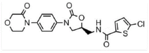
And the one or more water-soluble metabolites include at least one of the molecules:
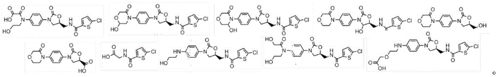
the wearable electronic digital treatment device may be configured as at least one of a sock, stocking, ankle bracelet, wristwatch display screen, wristband, ring, earring, sleeve, shirt, pant, shirt, tights, hat, garment, and body part accessory.
As shown in fig. 12, an ion-permeable reservoir contains sweat inducing material. The iontophoretic patch is in face-to-face contact with a skin surface containing sweat glands (e.g., in the wrist, arm, leg, sole, etc.). A microprocessor controls the application of electrical signals to cause the sweat inducing material to enter the skin and activate the sweat glands to produce sweat as desired. The sweat chemical detector element is functionalized for detecting one or more target molecules. The presence of chemicals in sweat is detected by a functionalized sweat chemical detector element which produces a signal dependent on the presence of the detected sweat chemical component, which signal is received by the microprocessor indicating the presence or absence of the target molecule.
According to one embodiment, a digital treatment device is provided for detecting adherence to ingestion of a pharmaceutical compound by a patient. A wearable electronic digital therapeutic device includes a chemical sensor for sensing one or more water-soluble metabolites present in the patient's blood to positively indicate the patient's adherence to the intake of a pharmaceutical compound. The pharmaceutical compound includes an initially ingested water-insoluble molecular structure that is metabolized to one or more water-soluble metabolites upon ingestion. Detection of one or more water-soluble metabolites by the wearable electronic digital therapy device indicates that the patient is adhered to the ingestion of the pharmaceutical compound.
The chemical sensor may be substituted for or supplemented by at least one of sweat, blood, urine, feces, interstitial and blood chemical sensors. A sweat-on-demand stimulator may be provided for stimulating the production of sweat by a patient, wherein the sweat is received by the chemical sensor for sensing one or more water-soluble metabolites. A data transmitter may be provided for transmitting data indicative of adherence of the patient to the intake of the pharmaceutical compound.
FIG. 112 is a cross-section of a pill comprising a water-insoluble target drug having a water-soluble metabolite detectable by the digital treatment apparatus of the present invention and a shell for positively indicating ingestion of the target drug by a patient.
The use of a therapeutic chemical (target drug) of the present invention with a detectable biological marker in combination with a digital treatment device of the present invention enables a reliable determination of patient adherence to a prescribed medication. The result is a very useful and positive indication that may be used to alert caregivers, hospitals, insurers, manufacturers, researchers, and other interested parties when a patient takes a predetermined dose, or an unscheduled dose, or a prescribed or non-prescribed medication. With positive indication of the presence or absence of a drug dose, the ingested or otherwise delivered water-soluble metabolites of the target drug can serve as a biometric indicator, can be determined by the same digital treatment device, specify the physiological effects of the administered drug, or lack the effects of the drug if a drug dose is missed or otherwise not occurred.
FIG. 113 is a cross-section of a pill having a water-insoluble target drug, having a water-soluble metabolite, and a rapid-release biomarker, wherein the rapid-release biomarker provides a relatively rapid detectable signal compared to the metabolism of the target drug for positively indicating by the detection of the biomarker that a patient persists in ingesting the target drug and determining a treatment condition for the target drug from the detection of the metabolite.
FIG. 114 is a cross-section of a capsule containing a water-insoluble drug of interest having a water-soluble metabolite and a time-release biomarker, wherein the biomarker remains detectable over a time associated with the time-release of the drug of interest to provide an indication of the activity of the drug of interest from ingestion to full or partial metabolism (or other activation/deactivation mechanism) for comparison with detection of the water-soluble metabolite.
FIG. 115 is a cross-section of a capsule containing a time-released water-insoluble target drug with a water-soluble metabolite and a time-released biometric indicator, wherein the biometric indicator remains detectable for a time associated with the time-release of the target drug, and wherein the capsule shell contains a fast-released biometric indicator that provides a relatively faster detectable signal than a slow-released biometric indicator for positively indicating patient adherence to ingestion of the target drug.
The pharmaceutical compounds of the invention comprise a first compound having a defined therapeutic effect on a patient and a second compound as a biological marker and having a metabolite as a chemical analyte, detectable by a wearable electronic therapeutic device. Detection of the chemical analyte by the wearable electronic digital therapeutic device indicates the presence of the pharmaceutical compound in the patient. The chemical analyte may be detected by the wearable electronic therapy device to positively instruct the patient to adhere to the ingestion of the pharmaceutical compound. The first compound may comprise the core of the pill. The second compound may comprise a coating on the core of the pill.
The compounds may be formulated as controlled release drugs in which at least a portion of the first compound has a delayed release of the biologically active chemical useful for performing the therapeutic action. The second compound may be formulated to provide a rapid, useful biometric indicator whose chemical analyte is detectable before the delayed release of the first compound into the biologically active chemical, wherein the chemical analyte is detectable at a faster rate than the controlled release of the drug into the biologically active chemical.
A third compound may be provided as another biological marker, wherein the third component includes another chemical analyte and is formulated for rapid use as a biological marker, and wherein the chemical analyte of the third compound is detectable at a rate greater than the rate at which at least a portion of the first compound becomes a biologically active chemical. The first compound may comprise a granular component contained in a capsule; and wherein the capsule has a shell structure for containing the first compound and comprises at least a portion of the second compound as an ingredient of the shell structure. The first compound may be formulated as a controlled release drug having a delayed release of at least a portion of the first compound as a bioactive chemical useful for performing a therapeutic effect, and the second compound may be formulated as a controlled release biological marker having a detectable chemical analyte at a rate corresponding to the rate at which the at least a portion of the first compound becomes a bioactive chemical. A third compound may be provided as another biometric indicator, wherein the third component comprises a chemical analyte and is formulated for rapid availability of the biometric indicator, wherein the chemical analyte of the third compound is detectable at a rate greater than the rate at which at least a portion of the first compound becomes a biologically active chemical.
A third compound may be provided as another biological indicator, wherein the third component comprises another chemical analyte and is formulated for rapid use in the biological indicator, wherein the chemical analyte of the third compound is detected at a rate greater than the rate at which at least a portion of the first compound becomes a biologically active chemical species. The first compound may comprise a granular component contained within the capsule and the second compound comprises another granular component contained with the capsule. The capsule may have a shell structure for containing the first compound and the second compound and including at least a portion of the third compound as an integral part of the shell structure. The first compound and the second compound may comprise a core of the pellet, wherein the third compound comprises a coating on the core of the pellet. The chemical analyte and the another chemical analyte may each comprise the same or different chemical species not normally present in the patient's blood. The therapeutic effect of the first compound may be to inhibit the initiation of blood coagulation, while the chemical analyte comprises a chemical not normally present in the patient's blood.
An apparatus for detecting ingestion of a pharmaceutical compound may include a wearable electronic digital treatment device including a biometric indicator detector for detecting a biometric indicator with a chemical analyte to positively indicate adherence of a patient to ingestion of a pharmaceutical compound. The pharmaceutical compound comprises a first compound having a defined therapeutic effect on the patient. The second compound is used as a biological recognition index and has a chemical analyte which can be detected by the wearable electronic digital treatment device. Detection of the chemical analyte by the wearable electronic digital treatment device indicates at least one of an absence and a presence of the pharmaceutical compound ingested by the patient. The wearable electronic digital treatment device may further comprise a data transmitter for transmitting data indicative of at least one of the absence and presence of a pharmaceutical compound ingested by the patient. The pharmaceutical compound may be, for example, for use in inhibiting the onset of blood clotting.
One embodiment includes a device for detecting intake of a pharmaceutical compound, including a wearable electronic digital therapy device. The wearable electronic digital therapeutic device includes a biometric indicator detector for detecting a biometric indicator having a chemical analyte, which is detectable after ingestion of the pharmaceutical compound. The pharmaceutical compounds include a first compound that, when biologically active in a patient, has a defined therapeutic effect on the patient, and a second compound that is a biological indicator whose chemical analyte is detectable by a wearable electronic digital treatment device. Detection of the chemical analyte indicates uptake of the pharmaceutical compound. The chemical analyte may be detected at a rate indicative of the biological activity of the first compound. The biological indicator may include at least one water-soluble metabolite having a chemical analyte, wherein the pharmaceutical compound includes a first compound having a defined therapeutic effect on the patient and has at least one therapeutically effective metabolite formed as the first compound becomes biologically active in the patient. The second compound is a biological indicator and has a chemical analyte of at least one water-soluble metabolite detectable by the wearable electronic digital therapy device, wherein the at least one water-soluble metabolite is formed by the patient's body at a rate indicative of the biological activity of the first compound. A data transmitter may be provided for transmitting data indicative of at least one of the absence and presence of the pharmaceutical compound ingested by the patient.
FIG. 116 is a flowchart showing an algorithm for detecting patient compliance with a predetermined intake of a drug of interest by detecting the presence of a biometric indicator, wherein the biometric indicator is a detectable metabolite. The detectable metabolite is detectable by the digital treatment apparatus of the present invention for positively indicating adherence of the patient to the intake of the target drug. The drug of interest may be administered as a tablet, capsule, other delivery mechanism, including but not limited to transdermal patch, intravenous drip, inhalation, eye drop, nasal spray, transdermal injection, implantable drug delivery mechanism, or other delivery vehicle.
A biometric parameter, such as blood flow, inferred or directly measured blood pressure, skin temperature, EMG measurements, etc., may be used to confirm or adjust the calculated expectation of the target drug effect/concentration.
An alarm may be sent to the smartphone via email, text message, telephone, or alarm timer to remind the patient when to take the target medication the next time (first step). The patient is then expected to take the drug of interest (second step).
There is a predetermined waiting period for the detection of the detectable metabolite (step three). For example, in the case of an inhaled quick release biomarker, the waiting time may be a few seconds after inhalation. In the case of tablets, even rapidly released detectable metabolites may take longer, detectable in blood for up to several minutes, even longer with sweat, using one or more biological recognition detectors, such as sweat chemical sensors as described herein, or other suitable detector/sensor mechanisms.
After a predetermined time (step three), an attempt is made to detect a detectable metabolite (step three). If a detectable metabolite is detected (step four), the presence and/or level of the detected detectable metabolite may be recorded and/or data indicative of the detected level (or simply the presence/absence of go/no go detection) transmitted as an indication that the patient adheres to the prescribed course of drug therapy.
If after the preset time (step two), no detectable metabolites are detected (step three), then it may be assumed that the patient is not adhering to the prescribed medication regimen and an alert may be sent via e-mail, text message, telephone, pager, text message or other communication (step seven) to let the caregiver, service provider, family member, patient, insurance company and/or medical institution know that the patient may not be taking the prescribed medication dose. After sending the alarm, particularly in the case of sending an alert directly to the patient or to a point-of-care provider with the patient, it may be assumed that the patient has taken the target drug and the biometric indicator, and then the preset wait time may again be allowed to elapse (step eight) before attempting to detect the detectable metabolite (step four).
If a detectable metabolite is detected (step six), a preset time may be allowed to pass after recording and/or transmitting data indicating the level or presence of a detectable metabolite (step ten). If the expected time for the next medication has not elapsed (step eleven), the blood level of the detectable metabolite may be detected again (step four), and if detected (step six), an indication of the detection is recorded or transmitted (step nine) to obtain a time history of the blood level of the detectable metabolite as an indication of the blood level of the target drug (which may be particularly useful if the blood level of the detectable metabolite correlates with the expected blood level of the target drug over time). When the patient is expected to take a dose of medication (eleventh step), an alert may be issued for the next dose, alerting the patient, caregiver, etc. that it is time to take the next dose (twelfth step), and detecting therein the expected and detectable metabolites of the dose of medication taken by the patient (second step).
This process may last for days, weeks, months or even years as long as the patient is prescribed the target medication, providing a detailed history of patient adherence to the prescribed medication. If biometric parameters such as those described herein with respect to other embodiments can also be detected, recorded and/or transmitted, a detailed history of the patient's treatment, course of treatment, measurements of treatment, etc., can be provided to improve care for a particular patient, and to provide important data in general along with other patient data to assist in new drug discovery, treatment modification, and a range of other advantages resulting from detecting, transmitting, storing and analyzing biometric data obtained directly from the patient during medication and/or other treatment.
FIG. 117 is a flow chart showing an algorithm for detecting the administration of a targeted medication that incorporates a biometric indicator into the same tablet or capsule or otherwise is taught to the patient at the same time or at a known time relative to the administration of the targeted medication. Detection of the biometric indicator is used as a positive indication that the patient has taken the target medication. The tablet, capsule, or other delivery mechanism containing the target drug may include a detectable biomarker to indicate, for example, patient compliance (e.g., taking a tablet containing the target drug and the biomarker), availability of the target drug into the bloodstream, timed release of the target drug, metabolism and/or excretion of the target drug, and the like. For example, in the case of timed release of the target drug, the biometric indicator may be delivered using the same time release mechanism as the target drug. For example, the biometric indicator may be an additional component added to the chemical composition of a new or pre-existing drug. According to one embodiment, the desired biometric indicator is a non-troublesome water-soluble compound that does not adversely alter normal body function, can be detected from sweat analysis, and does not adversely affect the beneficial effects of the drug of interest. As an example, a compound containing a Polyhydroxyalkanoate (PHA), which has biodegradable and biocompatible properties, can be used as a chemical analyte for detection.
The initial dose of the target drug is administered together with the biometric index (step one). For example, blood levels of the biometric indicators are detected by sweat chemical analysis (step two). The biometric indicator may be detected by other detection mechanisms, including but not limited to direct blood chemistry analysis, measured biometric indicators such as EMG, skin temperature, skin color, or changes in other detectable parameters. The detected drug level and/or biometric indicator is recorded (third step).
The detected data may be stored locally in a memory associated with the wearable electronic digital treatment device of the present invention or remotely in a memory of a smartphone, web server, computer or other external device. The detected data may be filtered, compressed, or otherwise conditioned prior to storage or transmission. Allowing a predetermined or calculated period of time to elapse to metabolize, activate, deactivate, treat, or otherwise change, for example, the blood level of at least one of the target drug and the biometric indicator (step four). After the time has elapsed, a biological indicator associated with the drug level is detected (step five), and the target drug level may optionally be inferred, directly or indirectly, from the detected biological indicator (step six). The detected drug level and/or the data of the biometric characteristic are recorded and/or transmitted to obtain, for example, a time history of the blood level of the biometric indicator as an indication of the blood level of the target drug (particularly where the blood level of the biometric indicator correlates with an expected blood level of the target drug over time).
As a further alternative, the detected biometric characteristic and/or the detected or inferred level of the medication may be used to notify a healthcare provider, family member, patient, artificial intelligence agent, medical payer, researcher, or other party that the provided data may be used to adjust the dosage of the medication taken by the patient or to indicate the population to take the medication. The detected biometric characteristic and/or drug level may be used to determine whether the biometric characteristic is acceptable (step eight). If not, an alarm, automatic action, and/or other indication may be used to indicate that the biometrical is unacceptable to increase or decrease the dosage of the drug. For example, if a larger dose would increase the effectiveness of the drug indicated by the detected biometric, the drug dose may be increased (ninth step), and if the detected biometric indicates that the drug dose is too large, or indicates that the drug dose is normal, the drug dose may be decreased (tenth step) to determine the minimum dose required to optimize the treatment. The feedback loop iterates from the detected biometric (second step).
FIG. 118 shows a water-insoluble anticoagulant and molecular pathways to water-soluble metabolites. In this example, the water-insoluble anticoagulant is rivaroxaban, which has a known pathway for water-soluble metabolites (Metabolism and evolution of rivaroxaban-an orals, direct Factor Xa inhibitor-in rates, logs and humans, Weinz et al, dmd. aspetjourals. org. ASPET journal on November 14,2018). Pharmacokinetic studies of rivaroxaban in animal models showed that rivaroxaban was rapidly absorbed after oral administration (absolute bioavailability in rats and dogs was 57-66% and 60-86%, respectively). Rivaroxaban has good pharmacokinetic profiles with increasing dose-proportional area under the concentration-time curve (AUC) and is demonstrated to be rapidly excreted via the renal and fecal/biliary pathways (Weinz C, buethorn U, Daehler HP, Kohlsdorfer C, Pleiss U, Sandmann S, Schlemmer KH, Schwarz T, and steinw (2005) BAY 59-7939 pharmacokinetics-an oral direct factor Xa inhibitor-in rats and dogs Xenobiotica 35: 891-. ) Rivaroxaban also showed pharmacokinetics and predictable pharmacodynamics of dose ratios in single dose (no more than 80 mg) and multiple dose studies in healthy subjects and patients, with no evidence of accumulation. In addition, rivaroxaban showed high oral bioavailability, rapid absorption, and safety and tolerability of good Kubitza D, Becka M, Voith B, Zuehlsdorf M, and Wensing G (2005a) BAY 59-7939 single dose safety, pharmacodynamics, and pharmacokinetics, an oral direct factor Xa inhibitor. Clinical pharmacology therapy 78: 412-. )
Figure 119(a) shows a water insoluble molecule of a therapeutic pharmaceutical compound. FIG. 119(b) shows a water soluble molecule that is a metabolite of a water insoluble molecule. According to one embodiment, a digital treatment apparatus is provided for testing patient compliance with administration of an anticoagulant pharmaceutical compound. The digital treatment apparatus detects, for example, patient compliance with ingestion of anticoagulant pharmaceutical compounds. The wearable electronic digital treatment apparatus includes a sweat chemical sensor for sensing one or more water-soluble metabolites present in the patient's blood to positively indicate the patient's adherence to anticoagulant pharmaceutical compounds. Anticoagulant compounds include an initially ingested water-insoluble molecular structure that is metabolized to one or more water-soluble metabolites upon ingestion. Detection of one or more water-soluble metabolites by the wearable electronic digital therapy device indicates a patient's adherence to ingesting anticoagulant pharmaceutical compounds. A sweat-on-demand stimulator stimulates the production of sweat by the patient, wherein the sweat is received by a sweat chemical sensor for sensing one or more water-soluble metabolites. The data transmitter transmits data indicating the patient's adherence to ingesting the pharmaceutical compound. The anticoagulant drug compound may comprise a water insoluble molecule.

And the one or more water-soluble metabolites include at least one of the molecules:
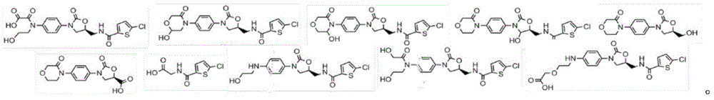
the wearable electronic digital treatment device may be configured as a sock, stocking, ankle bracelet, wristwatch display screen, wrist bracelet, ring, earring, sleeve, shirt, shorts, shirt, briefs, hat, or other garment or body part accessory.
Fig. 120 is a flow chart illustrating an algorithm for formulating and delivering a patch of bioactive water-soluble and/or nanoparticle components for a therapeutic pharmaceutical compound. An optimal concentration of bioactive water soluble and/or nanoparticle components is determined. These ingredients are, for example, bioactive compounds of ingested water insoluble drugs. For example, the components of the coagulation factor inhibitor may form nanoparticles and/or water-soluble components, which may be delivered transdermally from a medicinal patch, an ion dialysis patch, a microneedle patch, or other wearable configuration.
When ready for use, the patch is attached to the patient. An on-board microprocessor, activation and communication circuitry can be used to determine time and dosage (seventh step). The patch is activated to provide the dose (eighth step). For example, application of an electrical signal to an ion dialysis patch can be used to drive the absorption of a bioactive ingredient through the skin and into the patient's blood. After a preset period of time, the biometric parameters and/or biomarkers are detected and analyzed to determine physiological changes indicative of the effect of the treatment and/or metabolism by the components (step nine). The time and dose for the next patch activation is modified based on the determined physiological and/or predicted physiological change (tenth step). For example, the duration of time for which the patch is activated to provide a dose may be modified based on predetermined and analyzed data, and/or in the case of multiple patches each for administration of different components, the combination of components provided may be modified based on detected biometric data. The detected biometric data, environmental information and other relevant detection or inferential data are sent and/or recorded (tenth step) and the time and dosage of the bioactive ingredient for the next patch administered is again determined by the onboard or remote microprocessor (seventh step).
Figure 121 illustrates one embodiment of a wearable electronic digital treatment device of the present invention for analyzing and/or modifying medication and/or electrotherapy based on activated physiological changes and detected biometric parameters. The wearable electronic therapy device has one or more biometric detectors, each detector for detecting one or more biometric parameters. These biometric parameters are dependent on at least one physiological change in the patient during the treatment. A microprocessor receives the one or more biometric parameters and applies a probability analysis to determine whether at least one physiological change threshold has been exceeded, depending on the probability analysis of the two or more biometric parameters. An activation circuit activates an action based on the determination that the at least one physiological change is exceeded.
The therapeutic treatment may comprise an anticoagulant for treating a cardiovascular condition, wherein the at least one physiological change comprises an indication of a change in the cardiovascular condition. The activated actions may include sending an alert, modifying a therapy, and sending data dependent on at least one of the at least one physiological change, the one or more biometric parameters, the therapy, and the probability analysis. The probabilistic analysis may include determining from the data set of one or more biometric parameters whether the data set is acceptable to decide that a threshold of at least one physiological change has been exceeded.
The probability analysis may further include applying a statistical weighting to each of the one or more biometric parameters. The statistical weighting may depend on a predetermined value of an importance ranking with respect to other ones of the one or more biometric parameters when detecting the at least one physiological change of each of the one or more biometric parameters. The at least one biometric value is determined from one or more water-soluble molecules; and further comprising an on-demand sweat stimulator for stimulating the production of sweat by the patient and a sweat chemical sensor for sensing one or more water-soluble molecules.
According to one embodiment, a digital treatment device is provided comprising a wearable electronic treatment device having one or more biometric detectors, each detector for detecting one or more biometric parameters. These biometric parameters are dependent on at least one physiological change of the patient. A microprocessor receives the one or more biometric parameters and determines whether at least one threshold value of physiological change has been exceeded based on the one or more biometric parameters. An activation circuit activates an action based on the determined physiological change. The actions include at least one of transmitting an alert, modifying a therapy, and transmitting data that is dependent on at least one physiological change, one or more biometric parameters, and the therapy.
The at least one physiological change may be in response to an applied therapy, the therapy being at least one of a medication and an electrical therapy. Additional treatment methods, such as pneumatic and/or mechanical compression sleeve treatments, may also be applied. The method of treatment may include an anticoagulant for treating a cardiovascular disease, and the physiological change includes an indication of a change in the cardiovascular disease.
The actions may include communicating an alert, modifying a therapy, and communicating data that is dependent on at least one of the at least one physiological change, the one or more biometric parameters, and the therapy. The microprocessor may analyze the one or more biometric parameters using a probabilistic analysis including determining from a data set of the one or more biometric parameters whether the data set is acceptable to determine whether at least one threshold of physiological change has been exceeded. The probability analysis may further include applying a statistical weighting to each of the one or more biometric parameters, wherein the statistical weighting depends on a predetermined value of an importance ranking relative to other ones of the one or more biometric parameters when detecting at least one physiological change in each of the one or more biometric parameters. At least one of the one or more biological measurements may be determined from one or more water-soluble molecules. An on-demand sweat stimulator for stimulating the production of sweat by a patient and a sweat chemical sensor provided for sensing one or more water-soluble molecules.
The wearable electronic digital treatment device of the present invention can be configured to be worn anywhere on the body and used to detect biometric signals, collect and transmit biometric data, issue alerts or otherwise monitor a patient. The digital treatment device can be used to improve the treatment of existing medicines by supplementing the use of electrotherapy. As a non-limiting example, a digital treatment apparatus is provided for activating a muscle pump by applying a muscle electrical stimulation signal modified in accordance with the detected therapeutic effect of an anticoagulant medication.
A piece of wearable electronic clothing has at least one pair of electrodes for applying a muscle electrical stimulation signal through the patient's skin to induce involuntary contraction of one or more muscles adjacent to a deep vein vessel. Involuntary muscle contractions induce a squeezing action on the blood vessels and promote blood flow through the blood vessels in the direction of the patient's heart. A biometric signal detector detects a biometric parameter indicative of blood flow through the blood vessel. The biometric parameter depends on the therapeutic effect of the pharmaceutical compound used to inhibit blood coagulation. A microprocessor modifies the application of the electrical signal based on the detected biometric signal. The muscle electrical stimulation signal applied is varied according to the therapeutic effect of the pharmaceutical compound.
The biometric parameter may be detected in dependence on at least one of skin temperature, skin colour, blood flow, pulse, heartbeat, blood pressure, blood viscosity, skin firmness, swelling, blood chemistry, sweat chemistry, electronic biomarkers, chemical biomarkers and electromyography, or other suitable biometric or environmental condition. The applied electrical muscle stimulation signals may be passed as a series of electrical signals through two or more pairs of electrodes for sequentially compressing the blood vessel along its longitudinal axis to promote blood flow in the blood vessel, the direction of which is determined by the sequential compression and the one-way vascular valve within the blood vessel.
The biometric signal may be dependent on the heartbeat and the applied muscle electrical stimulation signal is modified to impart a squeezing action dependent on the heartbeat. The heartbeat biometric signal may be detected as at least one of a biometric optical signal and a biometric electrical signal from at least one biometric identifier in contact with a skin surface of the patient.
The muscle electrical stimulation signal may be applied to the at least one muscle through the skin surface from at least one electrode in contact with the skin surface. The biometric detector includes at least one electrode that applies a muscle electrical stimulation signal and is also used to detect heartbeats from the bioelectric signal. The biometric signal may be dependent on superficial venous blood flow, the applied muscle electrical stimulation signal being modified to impart a squeezing action dependent on superficial and/or deep venous blood flow.
Figure 122 is a flow chart illustrating an algorithm for determining drug administration patient compliance. As one example, determining compliance may be accomplished by analysis of biometrics or biomarkers based on activated sweat stimulation detection. The process begins at the time of an expected adherence event (step one) and allows a predetermined time to elapse (e.g., after a predetermined time from when the patient expects to ingest a pharmaceutical compound tablet to allow production of a metabolite) (step two). Physiological changes are activated, such as sweat stimulation activated by iontophoresis, in which a sweat stimulating chemical, such as kappa joe, is electrically driven into the skin on demand (third step). The presence of a biometric indicator is detected to indicate compliance of the patient to whom the drug is administered (fourth step). If the biometric indicator indicates that the medication patient adheres to medication (step five), adherence information is transmitted (step six). If the biometric indicator is not present (step five), it is determined whether the alarm time has been exceeded (step seventh). If the alarm time is exceeded, it is assumed that the patient has not taken or received the predetermined medicine, and an alarm is sent (eighth step). If the alarm time is not exceeded (seventh step), then a preset time will be allowed to elapse (second step) before activating the physiological change and looking for the presence of the biometric indicator (fourth step).
As one example of use, an initial flow of blood through a target vessel is detected. For example, the popliteal artery and/or vein or other blood vessels in the patient's leg may be monitored for blood flow by placing an optical blood flow sensor against the skin at a location such as the popliteal artery/vein. Optical blood flow sensors may be placed to detect capillary blood flow that receives and expels blood from the popliteal artery/vein and blood flow through these vessels inferred from capillary blood flow. The choice of directly measuring or inferring the vessels that detect blood flow depends on the goal of the analysis. For example, if the analysis is to determine the efficacy of an anticoagulant in the prevention or treatment of deep vein thrombosis, the target vessel may be the deep vein of the lower leg, and the flow rate may be approximately calculated by measuring the vessel located closer to the skin surface.
A therapeutic agent, e.g., an anticoagulant such as a factor XI inhibitor, is administered to the patient. The mode of administration may be oral and the therapeutic agent may comprise a time release formulation to maintain a desired concentration of the bioactive factor XI inhibitor in the bloodstream for a period of time (e.g., a once-a-day dose) to provide a desired therapeutic effect (e.g., prevention of thrombosis).
Allowing a predetermined time to elapse, for example, allowing the therapeutic agent to achieve a certain degree of therapeutic effect and/or allowing the concentration of the biologically active therapeutic agent to become available in the bloodstream.
Sweat stimulation can be activated by ion injection of a sweat stimulating chemical into the skin. The wearable electronic digital treatment device according to the invention utilizes on-demand sweat stimulation so that a sufficient amount of sweat is available when detection of a specific biomarker is required, even if the patient is sedentary. Sweat contains soluble biomarkers that can be detected by sweat chemical sensors based on changes in the electrical properties of functional structures connected to electrical traces under microprocessor control with appropriate amplification, signal conditioning and signal detection circuitry in electrical communication.
As examples of techniques and devices that may be used to form sweat chemical sensors, very small, inexpensive sweat chemical sensors may be fabricated using techniques in which all or part of the traces and/or functional structures may be nano-printed, for example, using PCT patent application by Busnaina et al, PCT/US2008/012977, 2008-11-21 U.S. patent submission, or U.S. patent by John j. daniels, 7,799,369B2, 2010-09-21 publication.
As a non-limiting example, a sweat chemistry sensor may be functionalized to detect the presence and/or concentration of biomarkers, such as thrombin and/or D-dimers. The presence of these biomarkers can indicate a physiological change, which may be the result of a condition of interest. By combining the automatic detection of these biomarkers with other biometric parameters, probabilistic analysis can be employed to improve the accuracy of determining the effectiveness of drugs and/or pharmaceutical treatments, to achieve automatic adjustment of drug delivery treatments, to alert care givers, patients, family members, etc., to provide useful continuous monitoring data for drug discovery and use of other large-scale population data sets, to adjust dosages, times, and other factors determined during experimental research and clinical trials, and other advantageous applications of the wearable electronic digital treatment device of the present invention.
Taking thrombin as an example, in the coagulation cascade, factor II is proteolytically cleaved in the first step of the coagulation cascade to form thrombin, ultimately resulting in the prevention of blood loss. F2 also plays a role in maintaining vascular integrity during development and postnatal life. Mutations in F2 can lead to various forms of thrombosis and coagulation dysfunction. Thus, according to the wearable electronic digital therapeutic apparatus of the present invention, the detection of thrombin biomarkers is utilized along with other biometric parameters, such as blood flow through a target blood vessel (as well as other biomarkers and biometric indicators described herein and/or current or future use for human or animal health), as an enhanced tool for the health and wellness of the individual and global population. Subsequent levels of biomarkers (e.g., thrombin) are again detected after sweat supply is induced by on-demand sweat stimulation.
Fig. 123 illustrates the component parts of a system for remote monitoring and control of a wearable electronic digital therapy device, and illustrates a wearable electronic and electronics block diagram with a sweat stimulator/collector. Examples of wearable electronic digital treatment apparatus of the present invention can be constructed in a convenient configuration that is comfortable, washable, and the same general construction of garments that are typically worn by patients and human health members almost daily. A sweat chemical sensor is shown. However, as with all of the described embodiments, the sensor may be any one or more of the various biometric parameter detectors described herein, or currently available or obtained by enabling the advancement of technology.
FIG. 124 is a flow chart illustrating an algorithm for analyzing the effectiveness of a treatment based on an activated physiological change and a detected biometric parameter. A physiological change, such as simulated sweating, is activated (step one). The initial biometric 1 value is detected (step two) and other biometric values are detected up to the initial biometric N value (step three). Treatment is applied (fourth step). A preset waiting time is allowed to elapse (fifth step) and then the physiological change is activated again (sixth step). Determining a therapeutic measure (seventh step), e.g. determining the concentration of a metabolite of an administered therapeutic pharmaceutical compound, or the change in blood flow through the vein under the effect of the administered therapeutic compound. The subsequent biometric 1 to biometric N values are detected (eighth step, ninth step). A probabilistic analysis is applied to one or more of the determined therapeutic measures and the detected biological measures (step ten).
The determined and/or detected data is recorded on an on-board memory and/or a remote server and/or transmitted to a trusted receiver (tenth step). It is determined that the analysis indicates that the threshold has been exceeded (twelfth step). For example, the threshold may be a change in blood flow, indicating a poor response to the treatment administered. If the threshold is not exceeded, the waiting time is reset (the thirteenth step) and the preset waiting time is allowed to elapse (the fifth step) and then the physiological change is continued to be activated again (the sixth step).
If the threshold is exceeded (twelfth step), it is determined whether there is an alarming situation (fourteenth step). For example, detection of a biometric value and a determined treatment measurement may indicate that the dose of treatment administered is insufficient to maintain adequate and/or improve blood flow. If the relevant condition is determined (step fourteen), an alarm is raised and the waiting time is reduced in order to activate the physiological change more quickly (steps five and six). Even if no relevant situation is determined (step fourteen), the latency can still be reduced as the threshold has been exceeded (step twelve) so that the activation, detection and analysis cycles are completed faster.
FIG. 125 illustrates an embodiment configured as a wristwatch, bracelet, sleeve, or armband. The wearable electronic device detects patient compliance with the medication intake schedule and sends a wireless confirmation or alert to an authentic recipient. A chemical analyte, preferably an administered metabolite, is detected by the wearable electronic device to confirm patient adherence. The wearable electronic device includes a sweat-on-demand stimulator that produces sweat only when it is desired to detect a chemical analyte. If the metabolite is a chemical analyte, no changes to the currently packaged drug may be made, nor new drug regulatory issues may arise. Water-soluble metabolites can be effectively detected by the on-demand sweat facilitator and sweat chemical sensor of the present invention.
In the cardiovascular context, the system can be used to detect biomarkers such as d-dimers and other proteins/components in the coagulation cascade. The appearance may be a simple bracelet, a foot chain, or even a smart watch with an activity tracking and display interface, thus achieving the additional important advantage of doctor/patient participation. Wireless signals are sent over the internet to alert care givers, hospitals, insurance companies, drug companies, family members, or other trusted recipients.
As an example, metabolites of the administered drug are tested to confirm patient compliance. An on-demand sweat stimulator is used to stimulate sweat to detect metabolites when needed. Wireless signals are sent over the internet to alert care givers, hospitals, insurance companies, drug companies, family members, or other trusted recipients. The wearable electronic device of the present invention is a non-invasive, positive intake medication indicator and sends a wireless signal to a caregiver or other trusted recipient confirming patient adherence.
FIG. 126 is a flow chart illustrating an algorithm for modifying a combination of medication and electrical therapy based on an activated physiological change and a detected biometric parameter. The physiological change is activated (step 1) and the initial biometric is detected (step 2). The drug and/or cosmeceutical treatment is administered (third step) and a preset time is allowed to pass (fifth step). The physiological change is activated again (step five) in order to be able to detect the subsequent biometric value (step six) and to determine whether the treatment method should be modified (step seven) on the basis of the detected biometric value (for example by comparison and/or exceeding a predetermined threshold). If the treatment does not need to be modified, the medication and/or electrotherapy is again administered (step three). If the treatment method should be modified (step seven), the treatment method is modified (step eight), and it is determined whether a relevant condition exists (step nine). If there is no worrying situation (ninth step), the cycle begins again and the physiological change is activated (fifth step). If there is an alarming condition (ninth step), an alarm is issued (tenth step).
FIG. 127 is a flow chart illustrating an algorithm for dose adjustment based on sensed in vivo drug levels and biometric parameters using the Body-in-the-LoopTM digital treatment apparatus. A predetermined dose of drug is administered (step one) and the level of drug in the blood is determined (step two). At least one biological characteristic related to the drug level is detected (third step), and the detected drug level and biological characteristic are recorded and/or transmitted (fourth step). The drug level in the blood is allowed to check again (sixth step) after a set period of time (fifth step). At least one biological characteristic related to the blood drug level is detected (step eight), and the data is again recorded and/or transmitted (step eight). If the biometric identification is determined to be acceptable (ninth step), then the drug dose is not changed (tenth step), the set time period is reset (eleventh step), the process continues back to another drug dose with no change from the previous dose (first step), and then the blood drug level is detected (second step) and at least one biometric identification is detected (third step).
If the biometrics is not qualified (ninth step), it is determined whether or not a poor drug effect is detected (tenth step), if so, it is determined whether or not the drug effect is worried (eighteenth step), and if so, an alarm is issued and medication is stopped (nineteenth step). If the effect is not significant (eighteenth step), then the set time period will be reduced (twentieth step) and the next dose of drug will be reduced (twentieth step) due to the detection of the adverse drug effect (twelfth step). The reduced set period of time is allowed to elapse (step 22), the process continues back to another dose of drug, which is reduced from the previous dose (step 1), and then the blood drug level (step 2) and at least one biomarker are detected (step 3). Note that at step one, the increase or decrease in the drug dose may be an increase or decrease in the frequency of the predetermined drug dose, and if the next drug dose is not predetermined, no drug is administered before the flow continues to detect the next blood drug level (step two).
If no adverse drug effects are detected (twelfth step), it is determined whether the biological measurements related to the blood drug concentration indicate that good drug effects have been detected (thirteenth step). If a good drug effect is detected, i.e. it is determined whether the maximum level of blood drug has been exceeded (fourteenth step), if so, an alarm is sent indicating a good effect (fifteenth step) and the flow continues to the tenth step.
If the maximum level is not exceeded (fourteenth step), the set period of time is decreased (sixteenth step), the drug dose is increased (seventeenth step), then the set period of time is allowed to elapse (twenty second step), and then the next scheduled drug dose is continued (first step). Note that if there is no predetermined dose of medication, the process may continue directly to the second step, so that the patient may be monitored periodically or continuously as a function of the set period of time.
Figure 128 illustrates a patch configuration of one embodiment. As with any of the wearable electronic configurations described herein, the patch may include a microprocessor, memory, battery, signal generation, activation, communication, signal detection, and other components that may be configured as flexible and/or stretchable circuitry. The patch may be disposable and/or have components such as an inductively rechargeable battery and a refillable reservoir.
Fig. 129 illustrates a multi-component configuration with a printed electronic flexible display with short and medium/long range relayed wireless communications of an embodiment. For example, a thin and lightweight printed electronic circuit and display may be constructed using the techniques described in U.S. patent document No. us20090176029a1, filed on 4.9.2002, the inventor of which, Daniels, the disclosure of which is incorporated herein by reference in its entirety.
Figure 130 illustrates a ring configuration of one embodiment. One or more RGB LEDS (or other illumination sources) may be used to communicate information to the patient and/or as a power saving function for optical coupling to a wireless relay. Figure 131 illustrates a foot ring configuration according to one embodiment.
Fig. 132 illustrates the positions of various biometric detectors/sensors/emitters/processors/actuators. The effect of the treatment can be analyzed based on the physiological change in activation and one or more detected biometric parameters. For example, the physiological change that is activated may be an on-demand stimulation of sweat. One biometric parameter that is detected may be the detection of coagulation cascade factors present in sweat. Another detected biometric parameter may be the detection of blood flow in a blood vessel of a body part, such as a leg. Another biometric parameter detected may be a change in the circumference of the leg caused by edema. Other biometric parameters are listed and described elsewhere. A sweat chemistry detector may be included for determining the concentration of coagulation cascade factors, blood gas components or other soluble molecules or small particles in the blood. According to an exemplary embodiment, the therapeutic effect may be a result of a drug delivery therapy, such as a drug therapy, such as an anticoagulant, and/or an electrotherapy, such as the application of EMS to activate a muscle pump. In addition, or alternatively, to analyzing the effect of the treatment, the progression or change in the disease can be determined by monitoring one or more detected biometric parameters.
The selection of one or more detected biometric parameters may depend on the physiological condition, disease, health level, therapy being monitored, or other circumstances for analyzing the effectiveness of the therapy. The biometric parameters may be detected instead of or in addition to the parameters described herein. For example, the biometric detection of biomarkers, such as thrombin and/or d-dimer, can be used to treat and monitor conditions associated with the contact system of coagulation and inflammation.
According to one embodiment, the blood flow information obtained by the blood flow detector may be used to detect changes in blood viscosity, which may indicate an alarming condition such as blood thickening due to thrombosis. The detected blood volume and blood flow measurements may be used, for example, with the concentration of red blood cells relative to other blood components to examine viscosity changes due to thrombotic events, rather than changes due to hydration (e.g., if the patient drinks and/or receives intravenous saline). Since viscosity changes due to hydration, the detected change in blood viscosity may not be indicative of thickening or thinning of the blood due to the change in clotting propensity. By detecting a value for red blood cell concentration (e.g., by detecting a change in reflected red light from a blood vessel) and normalizing for a given volume, it is possible to calculate a value that is compared to a threshold value (obtainable from a baseline patient reading) to indicate that the blood has become more viscous or thicker not due to a change in hydration, but rather due to the presence of a clotting factor.
Figure 133 illustrates an embodiment of a drug/nutraceutical combination therapy device for applying a nutraceutical signal in conjunction with an administered drug and detecting a bio-physiological response. The EMS electrodes apply electrical signals to the human body. The same electrodes can also be used as EMG electrodes to detect electrodes from the body. An electronic circuit is connected to the wearable electronic garment. Depending on the intended use, the EMS electrodes may be used for EMG or other signal detection to apply a bi-directional electrical signal through a plurality of individually addressable electrodes that are routed through an electrode multiplexing circuit and a signal multiplexing circuit for applying a continuous EMS signal and detecting biometric feedback, e.g., feedback from the lower leg of a patient. In accordance with one aspect of the invention, a digital treatment device garment has a plurality of individually addressable electrodes supported by the garment for applying successive EMS signals and detecting biometric feedback from the lower leg of a patient. The individually addressable electrodes are for at least one of applying a stimulating electrical signal to the skin of the patient and detecting a biometric electrical signal from the skin of the patient. At least one of a signal detector for detecting a bioelectric signal and a signal generator for generating a stimulation electric signal is provided. The electrode multiplexing circuit addresses the plurality of individually addressable electrodes by routing a biometric electrical signal from the patient's skin through one or more of the plurality of individually addressable electrodes to the signal detector and a stimulation electrical signal from the signal generator through one or more of the plurality of individually addressable electrodes to the patient's skin. A microprocessor controls the signal detector, signal generator, electrode multiplexing circuitry and other circuit elements.
The microprocessor may control the electrode multiplexing circuit to pass the bioelectric signal from the patient's skin sequentially through one or more of the plurality of individually addressable electrodes to the signal detector. According to this embodiment, one EMS signal source may serve a plurality of individually addressable electrodes, the EMS signals being routed according to a desired treatment, such as sequential squeezing of deep veins in the leg to promote blood flow to the heart. One or more EMS signal channels can be multiplexed and signals routed so that even a large array of individually addressable electrodes can be serviced by one or several signal generators, for example, to provide applied EMS signals of finer spatial resolution than the number of electrodes shown in the figure.
The microprocessor may control the electrode multiplexing circuit to simultaneously transmit a biometric electrical signal (e.g., indicative of muscle activity, heartbeat, etc.) from the patient's skin to the signal detector via more than one of the plurality of individually addressable electrodes. The microprocessor may control the electrode multiplexing circuit to simultaneously deliver the stimulation signals from the signal generator to the patient's skin via more than one of the plurality of individually addressable electrodes. The microprocessor may control the electrode multiplexing circuit to cause the stimulation electrical signal from the signal generator to sequentially pass through more than one of the plurality of individually addressable electrodes to the patient's skin. The microprocessor may control the electrode multiplexing circuit such that the stimulation electrical signal from the signal generator simultaneously reaches the patient's skin through more than one of the plurality of individually processable electrodes.
Figure 134 illustrates an embodiment of a drug/nutraceutical combination therapy device for monitoring physiological changes in response to administered drug and/or nutraceutical therapies. The biometric parameter may include a strain gauge formed from an elastic resistive strip that reversibly changes a detectable resistance value upon being stretched.
FIG. 135 is a flow chart illustrating an algorithm for applying a probability analysis to determine a physiological change of interest. As a simple, low cost early wearable electronic warning system, a first biometric value may be compared to a second biometric value to notice a physiological change, such as a thrombotic event, that indicates that a high risk patient may be experiencing an alarming condition. A patch, ring, bracelet, foot chain, sock, belt, or other wearable electronic device may be configured to automatically detect one or more biometric parameters indicative of a physiological change indicative of the onset of a condition of interest detectable at a body part such as a leg, wrist, foot, torso, neck, or the like.
A first biometric reading is made (step one). After a preset time (second step), a second biometric reading is performed (third step). The biometric reading is compared to see if the biometric reading has changed over time (fourth step). A probabilistic analysis is applied to determine if the change exceeds a threshold (fifth step) and if so, an alarm is sent (sixth step). If the change does not exceed the threshold (sixth step), then the present time may be reduced (optional seventh step) to more quickly detect and compare biometric readings (first, second, and third steps). Any of the sensors, detectors, and/or biometrics and biomarkers or other available or detected but unspecified biometrics described herein may be utilized as the detected biometrics described in this and other flow diagrams discussed herein.
Fig. 136 is a flow chart illustrating an algorithm of the warning system applying probability analysis to a plurality of biometric parameters. The first biometrical 1, biometrical 2 to biometrical N reading is taken (steps one, two, three). After a preset time (fourth step), a second reading of biometrical 1, biometrical 2 and biometrical N is carried out (fifth, sixth, seventh steps). If there is a change in any of the detected biometric indicators within the preset time (eighth step), a probability analysis is performed for each detected biometric change (ninth step). If any analyzed changes exceed a threshold that is predetermined or calculated for each biometric reading (tenth step), then an alarm is raised (tenth step) and the process flows back to detect the readings of biometric 1, biometric 2, through biometric N (first step, etc.). If none of the detected biometric change thresholds are exceeded (step ten), then a determination is made as to whether there are two or biometric changes within a preset time (step twelve). If there is a change in two or more biometric techniques (twelfth step), a probabilistic analysis is performed on the change in the two or more biometric techniques (fourteenth step), if the analysis indicates that the changes exceed a threshold (fifteenth step), and if so, an alert is sent (eleventh step) and the process continues to the first step. If there is no change in biometrics within a preset time (eighth step), the procedure continues to detect biometrics 1, biometrics 2 through the re-detection of biometrics N (first, second, third steps). If two or more biometric indicators do not change (step twelve), or the analyzed changes do not exceed a threshold (step fifteen), then to increase the frequency of testing, or to conserve battery power, sweat stimulation agents, and other consumables and data collection memory and transmission, the preset time can be changed (step thirteen) depending on the amount of testing desired to be increased or decreased, etc., and the process continues to step one. Any of the sensors, detectors, and/or biometrics and biomarkers or other available or detected but unspecified biometrics described herein may be utilized as the detected biometrics described in this and other flow diagrams discussed herein.
FIG. 137 is a flowchart illustrating an algorithm for a single parameter early warning system. As a simple, low cost wearable electronic early warning system, the first biometric value can be compared to the second biometric value to notice physiological changes that indicate a high risk patient may be experiencing a condition of concern, such as a thrombotic event. A patch, ring, bracelet, foot chain, sock, belt, or other wearable electronic device may be configured to automatically detect one or more biometric parameters indicative of a physiological change indicating that the onset of a condition is detectable at a body part such as a leg, wrist, foot, torso, neck, etc.
A first biometric reading is made (step one). After a preset time (second step), a second biometric reading is performed (third step). The biometric readings are compared to see if the biometric reading has changed over time (fourth step) and if the change exceeds a threshold (fifth step) an alarm is issued (sixth step). If the change does not exceed the threshold (sixth step), then the present time may be reduced (optional seventh step) to more quickly detect and compare biometric readings (first, second, and third steps). The detected biometrics described in this flowchart and other flowcharts discussed herein may be obtained using any of the sensors, detectors, and/or biometrics and biomarkers described herein or other available or detected but unspecified biometrics.
FIG. 138 is a flow chart illustrating an algorithm for performing a biometric fusion analysis on a plurality of biometric techniques to determine a physiological change. Biometric fusion is the use of multiple types of biometric data, or processing methods, to improve the performance of a biometric system. One type of fusion is fractional fusion, i.e., combining the scores of the matchers to improve accuracy. The scores used in the fusion may be obtained by using multiple types of data for each subject, typically applied for identification (e.g., face and fingerprint, or fingerprints from different fingers), multiple samples for each subject, multiple matchers on a single type of data, or a combination of these. According to the wearable electronic digital treatment device and application of the invention, biometric fusion analysis is used to improve the accuracy and effectiveness of treatment, monitoring and diagnosis of patients using biometric techniques of detection.
The first biometric 1, biometric 2 to biometric N reading is taken (steps one, two, three). After a preset time (fourth step), a second reading of the biometrics 1, biometrics 2 to biometrics N is performed (fifth step, sixth step, seventh step). If any one of the biometric indicators detected within the predetermined time is changed (eighth step), a probability analysis, for example, a central limit theorem or other statistical analysis model (ninth step) is applied to analyze the detected change of each biometric indicator (tenth step). If the analyzed change exceeds a threshold value that is predetermined or calculated for each biometric reading (tenth step), an alarm is raised (twelfth step) and the process returns to detecting readings of biometric 1, biometric 2, through biometric N (first step, etc.). If none of the detected biometric change thresholds is exceeded (the tenth step), then a determination is made as to whether there are two or biometric changes within a predetermined time (the tenth step). If there is a change in two or more of the biometric indicators (thirteenth step), a probability analysis, such as a biometric fusion analysis, is performed on the change in the two or more biometric indicators (fifteenth step), and a change in the biometrics based on the biometric fusion analysis is determined (sixteenth step).
If the analysis indicates that the change exceeds the threshold (seventh step) and if so, an alarm is raised (twelfth step) and the process continues to the first step. If there is no change in biometrics for a preset time (eighth step), process flow continues to test biometrics 1, biometrics 2 through biometrics N again (first, second, third steps). If the threshold change is not exceeded (tenth step) (seventeenth step), then the preset time may be reduced (fourteenth step) in order to conserve battery power, sweat stimulating agents, etc. consumables, as well as data collection memory and transmission, and process flow continues to the first step. Any of the sensors, detectors, and/or biometrics and biomarkers or other available or detected but unspecified biometrics described herein may be utilized as the detected biometrics described in this and other flow diagrams discussed herein.
FIG. 139 is a flowchart illustrating an algorithm of a single parameter thrombosis pre-warning system. As a simple, low cost warning system, skin temperatures at two or more locations on the same leg can be detected and compared to note changes in skin temperature, indicating that a high risk patient may be experiencing a thrombotic event. For example, a wearable electronic sock may be comfortable, washable, and easy to wear, and automatically detect one or more biometric parameters indicative of physiological changes, indicating the onset of a relevant cardiovascular condition detectable on the lower leg. Note that: other body part configurations are possible).
FIG. 140 is a flow chart illustrating an algorithm of a multi-parameter thrombosis pre-warning system. A wearable electronic therapy device has one or more biometric detectors, each detector for detecting one or more biometric parameters. Detecting a skin temperature 1 value (step one), a skin color 1 value (step two) and a circumference 1 (step three). These initial parameter values are compared with subsequently obtained values, wherein the biometric parameter is dependent on at least one physiological change of the patient during the treatment. After waiting a preset time (step four), the parameter values are checked again (steps five-seven). A microprocessor receives one or more biometric parameters. If there is no change in any of the biometric parameters (step eight), the cycle is repeated and the skin temperature 1 value is again detected (step one). If there is a change in any of the biometric parameters (step eight), the microprocessor applies a probabilistic analysis to determine if at least one physiological change threshold has been exceeded (step nine). The probability analysis and exceeding of the threshold may be based on only one of the biometric parameters, e.g. by noting a rapid change in leg swelling. If the threshold is not exceeded, the cycle repeats, again detecting a skin temperature 1 value (step one). Furthermore, or alternatively, if there is a change in two or more biometric parameters (step eleven), the analysis is based on a probability analysis of the two or more biometric parameters (step twelve), and exceeding the threshold value may depend on the probability analysis of the two or more biometric parameters (step thirteen). If the threshold is not exceeded, the cycle repeats, again detecting a skin temperature 1 value (step one). However, at step nine or thirteen, if the threshold is exceeded, an alarm may be sent (step ten) before the loop is restarted at step one. The alarm may be sent by an activation circuit that activates an action based on the determined physiological change that is exceeded. In addition to or as an alternative to sending an alarm, the action activated may depend on the medication being applied, e.g. the application of electrical medication is activated in addition to or as an alternative to medication. As a non-limiting example, the medication may be an anticoagulant medication taken by a high risk patient. In such a case, the detected biometric parameter may indicate that an alert should be sent and/or that cosmeceutical treatment should be applied.
Fig. 141 illustrates the location of blood vessels in the lower leg. Fig. 142 illustrates the location of blood vessels/vessels beneath the skin surface of the lower leg. Figure 143 illustrates a wearable electronic digital treatment device configured as a stocking for detecting biometric parameters including blood pressure using a blood pressure cuff and for applying compression therapy using the pressure cuff in conjunction with electrical and/or pharmaceutical therapy. The sock configuration of the wearable electronic device of the present invention can be used to monitor PAD patients at risk, using baseline measurements of blood flow at ankle-arm index (ABI) and ABI measurement points obtained from visits by physicians or at hospitals. The baseline ABI ratio and blood flow measurements are then compared to the blood flow measured in real time to determine if the PAD condition has changed.
The research literature supports this simple PAD monitoring as a prerequisite for early warning systems for high risk PAD patients. As an example of the biometric detector, a blood flow sensor of kyoto can detect a change in blood flow. Clinical ABI measurements are easy and routine and are likely to have been made to determine whether a patient has or is at risk of PAD. Blood flow through a blood vessel is proportional to the blood pressure of that vessel, and therefore blood flow measurements after ABI measurements are useful biometric parameters for determining subsequent changes in ABI ratios. A low cost, easy to wear product can be manufactured using a low cost blood flow sensor. Mathematics (blood pressure and blood flow changes during postural changes from sitting to standing: model development and validation, Mette s. olufsen et al, J Appl physiol.2005 month 10; 99 (4): 1523-.
Ankle-brachial index (ABI) is the ratio of systolic pressure (SBP) measured at the ankle to systolic pressure measured at the brachial artery. ABI is an indicator of atherosclerosis in other vascular sites and can be used as a prognostic marker for cardiovascular events and functional impairment, even without the symptoms of PAD. Because ABI is a ratio, its use in accordance with the wearable electronic digital treatment device of the present invention may not be affected by factors that increase or decrease blood pressure. For example, changes in blood volume after hemodialysis do not change ABI, and blood pressure decreases despite the large amount of fluid being removed.
That is, once there is a baseline ABI measurement, there should be no problematic relative change in ankle and brachial blood pressure measurements for the application, and ABI should remain relatively the same if the condition of PAD is not changed. Even if the patient varies in blood pressure from one ABI test to the next (due to changes in blood volume or movement), the ABI ratio will remain unchanged for the use described if the condition of the PAD is unchanged.
Since blood flow through a blood vessel is proportional to the blood pressure of that vessel, blood flow measurements after clinical ABI and blood flow baseline can be used as the biometric parameter detected to infer changes in ABI ratio, indicating changes in PAD status. In other words, wearable electronics for monitoring high-risk PAD patients would not require the complexity, battery consumption, volume, and eye-obstruction of a mobile blood pressure cuff that replicates the ratio of the clinical measurement ABI, rather, the baseline ABI and blood pressure measurements correlate with the constantly monitored blood flow changes at the measurement point.
One embodiment of the wearable electronic device and algorithm uses real-time biometrics of PAD symptoms, such as edema, skin temperature, and skin color, as well as blood flow measurements compared to baseline measurements to accurately determine that a changing PAD condition has exceeded a predetermined threshold, trigger a wireless alarm, send to a caregiver, family member, or other trusted receiver.
FIG. 144 is a flow chart illustrating an algorithm for inferring one or more biometric parameters to detect a physiological change. Baseline, resting blood pressure was measured at the wrist or arm (humerus) (step one) and ankle (step two) to determine baseline ABI (step three). The blood flow (fourth step) and the pulse are detected (fifth step), and the correlation between ABI, blood flow and pulse is determined (sixth step). For example, since blood flow through a blood vessel is proportional to blood pressure in that vessel, blood flow measurements and/or pulse measurements should be correlated with ABIs as baseline readings that can be used to detect biometric parameters to determine changes in ABI ratios, indicating changes in PAD status. This correlation can be stored as a baseline (step seven).
To check for PAD risk, blood flow (eighth step) and pulse (ninth step) are then detected and compared to baseline (tenth step). Statistical analysis, such as that associated with the central limit theorem (step eleventh) may be applied to analyze the comparison (step twelfth) to make a statistically significant decision as to whether the comparison exceeds a threshold (step thirteenth), where the threshold indicates that the high risk patient may have a change in physiological conditions, indicates a change in risk of peripheral arterial disease, and results in an alarm being issued (step fourteenth). If the comparison threshold is not exceeded, process flow returns to detecting subsequent biometric techniques for comparison to the associated baseline (steps eight through fourteen).
One embodiment of the wearable electronic digital treatment device of the present invention utilizes statistical techniques such as central limit theorem and sensor fusion in combination with cloud-based and/or locally embedded artificial intelligence for probabilistic data quality improvement.
As a non-limiting example of a probability analysis method suitable for use with the wearable electronic digital treatment device of the present invention, the central limit theorem is a statistical theory that indicates that the average of all samples taken from a particular population will approximately equal the average of that population, provided that a sufficiently large sample size is taken from a population with a finite level of variance. As the sample size increases, the resulting mean distribution (and associated margin of error) begins to approach a normal distribution. As a related statistical analysis technique, sensor fusion uses sensors intended to measure different but related data in order to capture relevant information deterministically from the different data. Embedded Artificial Intelligence (Artificial Intelligence) is a method that exploits the data collection source's local computing power, usually to provide a closed-loop drive based on derivative information.
When attempting to measure data using sensors, one always focuses on data quality and ultimately data utility. One key factor associated with ensuring data quality is the ability to capture and filter data outliers through outlier detection and sensor fusion. For example, in the case of the wearable electronic digital treatment device of the present invention, the data collected from the various biometric detectors may include outliers that enter the data set due to sudden patient movement (rising quickly from a sitting position), rapid environmental changes (going outside into a cold environment), temporary interruptions in the connection between the sensor and the body (repositioning of the wearable electronic device), and the like.
There are various methods to assist in tightening the band of data sets, including employing various statistical analysis methods and cross-correlation techniques. According to an exemplary embodiment, the central limit theorem is combined with data cross-correlation to improve the accuracy of the data.
By combining CLT with another approach known as "sensor fusion," this exemplary embodiment has the ability to produce higher data accuracy results while capturing raw data using lower quality (lower cost) sensors. Salina, B., Malathi, P., Arokia, P., An Efficient Data Fusion Architecture for Location Estimation, International Journal of Engineering Research and Technology (IJERT), ISSN No: 2278-. For example, a simple temperature sensor placed in a room has no way to "know" why a sudden temperature peak is measured. However, combining this temperature sensor with a motion sensor and/or light, vibration, sound sensors, it can be concluded that a large group of people has entered the room, or that a window has been opened, etc. By combining these different detection devices and aggregating the data over time, and employing predictive algorithms, greater data accuracy can be achieved. The result is more useful and accurate information.
According to an exemplary embodiment, the CLT is coupled to the data correlation such that the mean of the error band approaches a normal distribution, provided the sample size is large enough. As another illustrative example, test engineers often install instrumentation in the hot exhaust plume generated by gas turbine engines when operating in a test room. The most accurate measurement of the hot exhaust gas is obtained by placing a thermocouple device directly in the hot exhaust gas plume. Unfortunately, none of the thermocouple devices is able to withstand prolonged exposure to such hot exhaust gases. Thus, these devices initially produce valuable, accurate gas temperature data, but then burn out quickly. Using CLT and accessing data obtained from thermocouples placed at safe operating distances from the peak region of the gas plume, engineers accurately and routinely reproduced equivalent measurements of temperature generated at the location of the burned thermocouple sensor. This is accomplished by using a mathematical correlation relationship based on the initial temperature trace caused by the thermocouple associated with the thermal plume and the continuous measurements obtained by the probe acquiring the data at a safer location. Essentially, a "virtual sensor" is created using a combination of real-time captured data and mathematical correlations. According to the wearable electronic digital treatment device of the present invention, data trajectories of a plurality of data sources (biometric probes) are determined by correlating baseline measurements (e.g., which may be measured at a doctor's office using more accurate and expensive equipment and techniques) with continuous biometric measurements made over a relatively longer period of time using relatively lower cost biometric sensors and automated data detection.
As an exemplary embodiment, a method includes obtaining initial baseline biometric data using a biometric sensor with a relatively high degree of accuracy for detecting a biometric measurement. For example, the detected biometric measurements may be ankle and humeral measurements obtained at a physician's office to determine the ABI index. This higher accuracy of the detected biometric can then be later used as an initial baseline measurement to obtain an inferred change in ABI index. One or more biometric parameters are detected using the wearable electronic digital treatment device of the present invention, wherein the biometric parameters are dependent on at least one physiological change to the patient in response to the treatment and/or a change in a condition of interest at the patient.
The microprocessor then receives the high-precision detected biometric measurement (which may be stored in onboard memory) and one or more biometric parameters. The microprocessor applies a probabilistic analysis to determine whether at least one physiological change threshold has been exceeded, depending on the probabilistic analysis of the two or more biometric parameters and the highly accurately detected biometric measurement. An action is then activated based on the determined excess physiological change. The probabilistic analysis may include determining a trajectory (trend) of the detected biometric data by correlating the initial baseline biometric data obtained using the biometric sensor with relatively high accuracy with the detected biometric parameter dataset obtained using the sensor and detector of the wearable electronic digital therapy device. By applying probabilistic analysis techniques, such as CLT and sensor fusion, baseline information can be compared to data that is continuously acquired by the patient in daily life.
Another intrinsic value of CLT is that by relying on clustering of averages, we can more accurately predict and correlate individual population values. For example, in a system with a large number of sensors, each producing data with a relatively high standard deviation, CLT's theorem tells us that by summarizing the amount of this large group of samples, we can predict the average of the measured phenomenon more accurately. In other words, the large number of sensors, each typically producing highly uncertain data, exposed to a single data source, produces a large amount of data that, when summed, fall into a more closely related "normal" (bell curve) distribution with mean and standard deviation values that are within the "actual" data values of the data source.
According to the wearable electronic digital treatment device of the present invention, accurate prediction of unknown values is obtained by measuring the correlation values of the entire large sample population and calculating the mean and standard deviation of the correlation values with respect to the desired measurement values. Putting this into practice, the wearable electronic device can use a series of relatively low precision sensors to generate data from a normal distribution of measurements and related data with a high probability of falling within a narrow mean.
Particularly to the installation of low cost measuring devices into wearable garments, the highest practical accuracy data is analyzed from the use of low cost sensors of smaller size and power consumption. Other characteristics, such as physical size, flexibility, robustness of the sensor, etc., will also influence the actual design decisions. By employing these statistical and mathematical methods to quantify and tabulate the data we have captured, a practical method has been developed to produce high value information at a low relative infrastructure and financial cost. In particular, these inventive wearable garments can provide highly accurate clinical quality biometric data using sensor fusion and central limit theorem techniques with embedded AI (artificial intelligence) operations through software running in real time, at a cost that is only a fraction of that of using laboratory-level sensors.
Figure 148 shows the hand of a patient with upper limb contracture. Figure 149 shows the hand and forearm of a patient with upper limb contracture. Since the natural resting position of the hand is a curl and bend at the wrist, when the patient loses adequate control of the muscles of the lower arm, the hand and arm collapse to the position shown in the photograph. Contracture deformities are the result of stiffness or contraction of the body's connective tissue. This may occur in muscles, tendons, ligaments and skin. Contractures can also cause deformities of the joint capsule, which is a dense fibrous connective tissue that stabilizes the joint. Contractures restrict normal movement and occur when the normally flexible connective tissue becomes less flexible. Muscle contractures are related to the shortening and tightening of muscles.
Figure 150 shows the muscle and EMS electrode positions of one embodiment of the contracture sleeve of the present invention. Figure 151 shows an embodiment of a contracture sleeve of the present invention showing the location of electrodes used to apply EMS to the lower muscle of the forearm. Figure 152 shows the muscle and EMS electrode positions of one embodiment of the contracture sleeve of the present invention. Fig. 153 shows an embodiment of a contracture sleeve of the present invention, showing the location of electrodes used to apply EMS to the upper muscle of the forearm.
According to one embodiment of the wearable electronic digital treatment device of the present invention, two or more electrodes are in face-to-face electrical communication with skin overlying muscles of the upper forearm, such as extensor muscles and other muscles of the upper forearm. The EMS signal through the electrodes causes involuntary muscle contractions, resulting in rotation of the hand at the wrist. This involuntary movement results in stretching of the flexors and other muscles of the lower forearm. Electrodes may be provided in communication with the skin overlying the lower forearm muscle to apply EMS, TENS and other therapies to improve tone and prevent atrophy, and to help stretch and strengthen the lower arm muscle of patients with stroke, multiple sclerosis or other contractures.
Fig. 154 shows the lower forearm muscle in the contracted position. Fig. 155 shows the upper muscle of the forearm in a contracture state. Fig. 156 shows the lower muscle tension contracture of the forearm. Fig. 157 shows the condition of forearm upper muscle stretching contracture. Contractures are very common in people who suffer strokes and cause paralysis. Other causes include genetic diseases or diseases that develop in early childhood, such as muscular dystrophy, cerebral palsy, central nervous system diseases, such as multiple sclerosis or parkinson's disease, and inflammatory diseases, such as rheumatoid arthritis. Physical therapy and occupational therapy are the two most common methods of treating contractures, and help to increase the range of motion and strengthen muscles of patients. Physical therapy courses need to be attended periodically to achieve optimal results and improve performance through hand treatment. Drugs may be prescribed to reduce inflammation and pain. For example, for stroke or cerebral palsy patients, botulinum toxin (Botox) can be injected into muscles to reduce tension and reduce spasticity.
Fig. 158 illustrates the components of a system for remotely monitoring and controlling a wearable electronic digital treatment device, and illustrates a block diagram of a wearable electronic contracture sheath and electronics. Examples of wearable electronic digital treatment apparatus of the present invention may be configured in a convenient configuration that is comfortable, washable, and easily worn by patients and human health members. A contracture sleeve with a smartphone interface is shown. However, as with all of the described embodiments, the system may have algorithms, components, and applications for any one or more of the various detection, analysis-treatment, and/or application treatment configurations described herein.
Fig. 159 is a flow chart of an algorithm for detecting, analyzing-treating, and applying wearable electronic digital therapy. The wearable electronics includes biometric and/or environmental sensors and detectors that detect data related to the patient. The detected data is analyzed by an on-board microprocessor and/or remote computer. The data is analyzed to determine an appropriate treatment for the patient based on the detected data and/or based on calculations of the detected data and external conditions (e.g., passage of time). If no treatment is necessary.
Fig. 160 is a flow chart of an algorithm for a contracture socket. The contracture sleeve may be configured to automatically apply an EMS signal to the upper forearm muscle to cause involuntary muscle contraction, rotate the hand at the wrist, and stretch contracture of the lower forearm muscle or tightening of muscles, ligaments, etc. of the patient. The application of the EMS signal may be in response to detected data, such as detected biometric data. For example, if accelerometer and/or EMG biometric data is detected (step one), the data is analyzed (step two) to determine a treatment or modification to a treatment (step three). If the analysis indicates that no treatment or modification to the treatment is required, the flow continues to step one. If the analysis indicates that an application therapy or application modification therapy should be performed, then the therapy is modified (fourth step) and then applied (fifth step). For example, if a lack of extension motion of the contracted hand is detected (step one), it may be determined to modify the applied EMS therapy (step three), determine a modification to the therapy (step four) and apply a modified EMS signal (step five) as compared to analyzing the data (step two) to indicate a lack of motion. For example, the modification may be a series of automatic involuntary muscle contractions that, when the duration (e.g., one hour) has elapsed, will stretch the contractual hand without sufficient movement and stretching of the contractual hand.
FIG. 161 is a flow chart of an algorithm for pinching the sleeve. Many everyday life skills require the ability to knead and grab. For example, fastening shirts, pulling pants, wearing socks, opening doors, opening closed bags, holding pens, toothbrushes, spoons, tying laces, and many other skills required for normal daily life are often difficult or impossible for patients suffering from stroke, trauma, multiple sclerosis, parkinson's disease, or other diseases or conditions. According to one embodiment of the wearable electronic digital treatment device of the present invention, the forearm sleeve includes an electrode to which an EMS signal is delivered to cause involuntary muscle contraction to complete a predetermined action.
EMG pattern data is detected (step one). For example, a patient may have a small amount of control over the muscles of their forearm to show the intent of the motion to reach the object, but not have enough control to extend the reach and grasp the object. To help determine the intent to move, an accelerometer or other data (including a button pressed by the patient's other hand or a voice command by the patient) may be detected (step two). Other biometric data, such as EMG and/or accelerometer data detected by a gesture or other body part of the patient's other hand) may also be detected to indicate intent to move (step three). The data is analyzed to determine whether the intention is to exercise (step four), and if not, the flow returns to the step one to prepare for detecting the intention to exercise. If it is determined that there is an intention to exercise (fourth step), a correct muscle contraction sequence is determined (fifth step) to accomplish the intention to exercise. A series of EMS signals are applied to the appropriate muscles at the appropriate times to complete the motor intent (sixth step). Involuntary muscle contractions result in the completion of motor intent, for example, stretching the patient's hand, pinching, and grasping an object.
Figure 162 illustrates an exemplary embodiment showing bi-directional electrical signals applied through a plurality of individually addressable electrodes routed through electrode multiplexing circuitry and signal multiplexing circuitry for applying successive EMS signals and detecting biometric feedback from, for example, a patient's arm muscles or lower legs. In accordance with one aspect of the invention, a digital treatment device garment has a plurality of individually addressable electrodes supported by the garment for applying successive EMS signals and detecting biometric feedback from a patient's muscle. The individually addressable electrodes are for at least one of applying a stimulating electrical signal to the skin of the patient and detecting a biometric electrical signal from the skin of the patient. At least one of a signal detector for detecting a bioelectric signal and a signal generator for generating a stimulation electric signal is provided. The electrode multiplexing circuit processes the plurality of individually addressable electrodes by at least one of: transmitting a biometric electrical signal from the patient's skin to the signal detector via one or more of the plurality of individually addressable electrodes or electrode pairs; the stimulation electrical signal from the signal generator is delivered to the patient's skin via one or more of a plurality of individually addressable electrodes or electrode pairs. A microprocessor controls the signal detector, signal generator, electrode multiplexing circuitry and other circuit elements.
The microprocessor may control the electrode multiplexing circuit to pass the bioelectric signals from the patient's skin sequentially through one or more of the plurality of individually addressable electrodes or electrode pairs to the signal detector. According to this embodiment, one EMS signal source can serve a plurality of individually addressable electrodes, the EMS signals being routed according to a desired treatment, such as sequential squeezing of deep veins in the leg to promote blood flow to the heart, or sequential application of involuntary muscle contractions to accomplish a desired movement. One or more EMS signal channels can be multiplexed and signals routed so that even a large array of individually addressable electrodes can be serviced by one or several signal generators, for example, to provide finer spatial resolution of the applied EMS signal than the number of electrodes shown in the figure.
The microprocessor may control the electrode multiplexing circuit to simultaneously transmit a biological recognition electrical signal (e.g., representative of muscle activity, heartbeat, etc.) from the patient's skin to the signal detector via one or more of the plurality of individually addressable electrodes or electrode pairs. The microprocessor may control the electrode multiplexing circuit to cause the stimulation electrical signal from the signal generator to simultaneously reach the patient's skin through more than one of the plurality of individually treatable electrodes or electrode pairs. The microprocessor may control the electrode multiplexing circuit to cause the stimulation electrical signal from the signal generator to sequentially pass through more than one of the plurality of individually addressable electrodes or electrode pairs to the skin of the patient. The microprocessor may control the electrode multiplexing circuit to cause the stimulation electrical signal from the signal generator to simultaneously reach the patient's skin through more than one of the plurality of individually treatable electrodes or electrode pairs.
Figure 162 illustrates one embodiment of wearable electronics of the present invention that can serve as an interface to selectively apply transcutaneous electrical nerve stimulation and selectively detect electromyography via the same electrodes and/or circuit elements. FIG. 163 illustrates a plurality of individually addressable electrodes for receiving bioelectrical signals from beneath the patient's skin and applying EMS signals to the moving element. FIG. 164 illustrates a plurality of individually addressable electrodes showing muscles and nerves under the skin of a patient. FIG. 165 shows a configuration of a plurality of individually addressable electrodes with the bio-signal detection/application electrodes arranged in pairs approximately coincident with the long axis of the muscle of the forearm of the patient, along with a reference electrode arranged between the electrode pairs. FIG. 166 shows a three-dimensional view of an individually addressable electrode pattern of a forearm sleeve.
The microprocessor may control the electrode multiplexing circuit to cause the biometric electrical signal from the patient's skin to pass sequentially through more than one of the plurality of individually addressable electrodes or electrode pairs to the signal detector. The microprocessor may control the electrode multiplexing circuit to cause the biometric electrical signals from the patient's skin to reach the signal detector simultaneously through more than one of the plurality of individually addressable electrodes or electrode pairs. The microprocessor may control the electrode multiplexing circuit such that the stimulation electrical signal from the signal generator is simultaneously delivered to the patient's skin via one or more of the plurality of individually addressable electrodes or electrode pairs. The microprocessor may control the electrode multiplexing circuit to cause the stimulation electrical signal from the signal generator to sequentially pass through more than one of the plurality of individually addressable electrodes or electrode pairs to the skin of the patient. The microprocessor may control the electrode multiplexing circuit to cause the stimulation electrical signal from the signal generator to simultaneously reach the patient's skin through more than one of the plurality of individually treatable electrodes or electrode pairs.
FIG. 166 illustrates an electrode pattern for a HHMI forearm sleeve for detection and application using a single signal detector and a single signal generator, with a multiplexing circuitry for routing electrical signals. A microprocessor controlled signal multiplexing circuit may be provided for routing electrical signals from the signal generator through the electrode multiplexing circuit to the skin of the patient and from the skin of the patient through the electrode multiplexing circuit to the signal detector. A microprocessor controlled memory may be provided for storing data dependent on the biometric electrical signal; and a communication module for transmitting the stored data for analysis by the remote network device. The housing may be comprised of an elastic fabric material and the individually addressable electrodes are dry electrodes that may be formed by printing an elastic conductive ink.
The same one of the plurality of individually addressable electrodes is capable of both detecting a biometric electrical signal from the skin and applying a stimulating electrical signal to the skin. The microprocessor may control the electrode multiplexing circuit to cause the plurality of electrodes to sample the biometric electrical signal at a sampling rate effective for the signal detector to detect the biometric signal as an electromyographic signal originating from a subcutaneous motion unit indicative of contraction of two or more muscles from the patient.
The microprocessor may control the electrode multiplexing circuit to process the plurality of electrodes so as to cause involuntary contraction of the patient's muscles at an effective pulse rate as the applied pulses are stimulated by the stimulation electrical signal. The microprocessor may control the electrode multiplexing circuit to process the plurality of individually processable electrodes by at least one of: the biological recognition electrical signal from the patient's skin is transmitted to the signal detector via one or more of the plurality of individually processable electrodes or electrode pairs, and the stimulation electrical signal from the signal generator is transmitted to the patient's skin via one or more of the plurality of individually processable electrodes or electrode pairs. At least one of the inertial measurement unit, the sensor, the detector and the transducer may also be provided supported by the housing.
Fig. 167 illustrates a patient's arm 16 without skin, showing the relative positions of muscle groups 18 of the arm 16. Fig. 168 shows an arm 16 with HHMI sleeves with electrodes 14 directed to individual muscles 18 or muscle groups 18. The HHMI sleeve may include a relatively small X-Y grid of signal receiving transducers or electrodes 14 and relatively large signal applying electrodes 14, for individual muscles 18 or muscle groups 18, or as shown, the electrodes 14 may be of uniform size and distribution. The HHMI can be in the form of a garment that is comfortable and easy to wear, with little restriction to movement when worn.
Electrical signals are applied to the patient 12 through a plurality of electrodes 14. Each electrode is disposable and is in electrical communication with one or more biological components of the patient 12. At least one of the electrodes is individually addressable to be selectively in an on state or an off state. In the on state, an electrical signal flows through the electrodes to at least one biological component of the patient 12. In the off state, the electrical signal does not flow through the electrodes to the biological component. Each electrode is individually addressable to detect electrical activity of the biological component during a signal detection operation and to apply an electrical signal to the biological component during a signal application operation.
The HHMI may be configured as an arm-sleeve that is part of a garment, or as a stand-alone wearable electronic device that maps the source of electrical activity (subcutaneous muscles 18 and nerves) to determine the optimal location for detection and application of electrical signals for a particular patient 12. For example, neuromuscular electrical stimulation is performed in the form of low-frequency, relatively high-intensity pulses.
According to the wearable electronic digital treatment device of the present invention, the electronic circuit may comprise a TENS and an EMS signal generator. For example, activation of the muscle pump may be accomplished with an EMS signal, which may be of such a low intensity as to be barely perceptible. In other words, for some patients, strong muscle contraction (and thus strong EMS signals) may not be required to adequately pump blood through the deep vein. Meanwhile, conventional TENS generally has a rapid analgesic effect. But when the stimulus is turned off, the effect quickly disappears. However, the analgesic effect of low frequency TENS takes longer, but pain relief by endogenous opioids can last for a long time. Since the wearable electronic sock of the present invention is comfortable and easy to wear for a long time, it can be used to apply a TENS signal having a rapid analgesic effect, an EMS signal that effectively assists activation of a muscle pump, and a more durable low frequency TENS signal, so that a patient can always receive pain relief caused by an electric drug using an intrinsic electrical system of the body (without an analgesic or as an auxiliary means) even when the muscle pump is activated by the EMS. Since the human body will tend to integrate the applied signals, it is possible to rapidly switch between TENS and EMS signals, applied continuously (or intermittently) through the same electrode. In addition, the use of EMS and TENS signals can maximize the effectiveness of the muscle pump to assist blood flow through the deep vein, and the variable TENS used can be easily controlled (or automatically controlled) by the patient through our smartphone application.
The pulse may be biphasic, triggering the alpha motor nerve causing muscle movement. The higher the intensity of the electrical stimulation, the more muscle fibers are excited, resulting in a stronger contraction. The contraction may be of different speeds and durations, depending on the characteristics of the electrical signal applied. The characteristics of the applied electrical signal may be controlled to cause isometric and/or isotonic muscle contractions that result in muscle tension without changing muscle length, which results in shortening of the muscle. In accordance with the haptic interface of the present invention, a computer controls the characteristics of electrical signals applied to motor neurons of, for example, the patient's nervous system to cause desired sensation and/or muscle movement. Motor neurons are stimulated by the body's nervous system, producing results similar to those when neurons are stimulated by computer-controlled electrical stimulation.
In accordance with the haptic interface of the present invention, a computer-controlled electrical signal can be applied, the signal characteristics of which can be effective to stimulate one or more haptic receptors on the skin. For example, the signal characteristics may be controlled to selectively stimulate receptors with different receptive fields (1-1000 square millimeters) and frequency ranges (0.4-800 hertz). For example, a broad receptor, such as the corona body of pasini, produces a vibratory scratchiness sensation. Small range receptors, such as mekerl cells, produce a sense of pressure.
HHMI can also be used for applications such as accelerated learning, brain injury rehabilitation, military and sports training, and drone/robot remote control and sensing. In some configurations, the HHMI includes a thin, flexible sleeve that is worn inconspicuously by the patient. The cartridge has a number of small electrodes 14 in contact with the skin surface, connected in a matrix and processed using electronic technology borrowed from active and passive matrix video displays. A lightweight, comfortable tactile sleeve can be configured with electrode size and density that automatically calibrates the patient's unique anatomy. The haptic sleeve provides accurate electrical activity detection (e.g., detecting muscles 18 and nerves involved in even subtle arm movements, indicating the onset of sustained parkinson's tremor) and nearly instantaneous electrical signal application (resulting in involuntary and accurate muscle and nerve impulses that counteract and negate the otherwise occurring adverse arm tremor). The applied electrical signal and the resulting muscle contraction is perceived by the patient as a massage sensation. In this case, the use of HHMI provides a wearable electronic device that effectively alleviates tremors caused by stroke, accident or parkinson's disease as a non-invasive, non-chemical means.
In accordance with another aspect of the present invention, a plurality of tactile cues are generated that are perceivable by patient 12. The tactile cues are received by the patient 12 as computer-controlled, continuously generated electrical signals. These electrical signals evoke involuntary body part movement, causing at least a prompt for at least one of the predetermined movements. Alternatively, or in addition, these signals evoke the perception of the patient 12 with a predetermined somatosensory sensation dependent on the computer-controlled serially generated electrical signals.
Figure 169 shows an example where a particular muscle (biceps) is contracted by application of a transcutaneous electrical signal. The electrical signal is applied in the form of a dc voltage between the first and second electrode sets. As shown by the other circuits, the circuit may be modified to include circuit elements to determine the appropriate set of electrodes to evoke the desired muscle response during the calibration mode, for example. In the calibration mode (described in more detail below), these same first and second electrode sets are used to detect electrical activity that occurs when the patient 12 performs a known action, such as lifting the hand to the chest (contracting biceps). Additionally, or alternatively, the appropriate electrode set to invoke the desired muscle response may be inferred from the calibration data, as the general physiology of the human arm 16 is well known. In this case, the calibration mode and/or the refinement mode provide fine tuning of the predetermined electrode pattern, where the predetermined electrode pattern is based on human physiology and the fine tuning is based on the specific electrical activity detected for the patient 12 during the calibration mode. Strain wires or the like may also be used to detect muscle movement, and/or memory metals for contracting and applying compressive forces, provided as conductive paths to the electrodes 14 or as separate components.
The haptic interface of the present invention uses sensory feedback and algorithms to properly control the characteristics of the electrical stimulation. Muscle contractions may be induced such that the movements of the body part of the patient 12 (e.g., the fingers) are the same as those voluntarily performed by the patient 12 using precisely controlled muscle movements.
Muscle contraction and changes in body part position can be used as a measure in the calibration process, and feedback can also be obtained when the application of electrical stimulation causes automatic and involuntary movements of the patient's body part. The sleeve may include sensors for measuring changes in muscle shape or body part position, or for applying pressure, such as compression or vibration. For example, shape memory alloys (which may form a sheath around or otherwise in communication with the electrode leads) or piezoelectric or mechanical vibrators may be used to apply tactile cues in the form of pressure or vibration under the control of electrical signals from a computer or microprocessor.
The HHMI is constructed of a thin flexible layer of material such as a conductive stretchable fabric, a flexible insulator, a flexible circuit board, or the like. These materials may be braided, woven, closed cell, open cell, film, or other suitable structures.
The layers, adhesive layers and constituent elements of the HHMI can be printed using a 3D printer, or formed by batch or roll-to-roll manufacturing processes, including lamination, screen printing, inkjet printing, self-assembly, vapor deposition, spray coating.
The HHMI may be formed as a sleeve, glove, legging, shirt, full body garment, or the like, and has a flexible, comfortable fit that encourages the electrode 14 to make face-to-face surface contact with the skin of the patient 12. The gel electrode 14 may be used, but has some disadvantages. The electrode structure described herein provides a thin and flexible structure specifically designed for compressive face-to-face contact. In either case, the transfer of electrical signals between the conductive surfaces of the electrodes and the skin of the patient 12 must be effectively accommodated.
As shown in FIG. 71, since each person's body is different, at the beginning of the calibration mode (step one), the patient 12 is asked to make a first calibration movement (step two). If the patient is too paralyzed to make detectable movement, the caregiver can perform a calibration movement and sensors, such as accelerometers and amplified EMG detection are used to detect the calibration movement. The patient 12 performs a known action (third step) that causes nerve firing and muscle contraction, such as an action that replicates the action of eating. The electrical activity (amplified EMG) and/or physical movement of the first movement is detected (step four), and the characteristics of the electrical activity produced by the body (e.g. the electromyographic signals produced by the nerves and muscles 18) are sensed and stored (step five). In addition to the electrical activity generated by the body, other physiological changes may be detected, such as changes in the shape of the patient's arm 16 caused by muscle contraction. These physiological changes are useful for calibrating the human-machine interface of the present invention and can also be used to determine the expected electrical signal of the patient. Particularly for patients with poor EMG signal strength, other electrical and muscular activities that are detected and used for calibration, control intent, condition of the patient 12, etc., may include EKG and EEG, as non-limiting examples.
The next calibration action is indicated to the patient 12 (sixth step), the patient 12 performs the action (seventh step), electrical activity is detected (eighth step), and characteristics of the detected electrical activity are stored (ninth step). If the calibration procedure is not complete (step nine), another next calibration action is prompted (flow returns to step six). If the calibration procedure is complete (ninth step), the detected electrical activity signature is mapped onto the calibration movement (tenth step). Through this process, the electrical signals and electrical signal sources (muscles 18 and nerves) associated with known movements are calibrated for a single patient 12, and a signature associated with each respective muscle 18 and nerve for each respective calibrated movement is stored for the patient 12.
In an automatic mode of action, for example for VR stroke rehabilitation, calibration data is used to determine characteristics of computer-generated electrical activity that cause desired automatic and involuntary movements of a patient's body part. The result is that the patient perceives involuntary movement as being caused by externally applied forces.
FIG. 171 is a flow chart showing an algorithm for refining the calibrated HHMI using measured motion of patient 12. This exemplary algorithm provides for further tailoring of the HHMI to interface with a particular patient 12. Since each individual's body is different, in the calibration mode, the patient performs a known task, causing nerve firing and muscle contraction, such as replicating a feeding motion. The characteristics of the electrical activity produced by the body (e.g., myoelectrical signals produced by nerves and muscles 18) are sensed by sensory sensors (i.e., electrodes 14 shown herein). The sensors are used to calibrate the position, relative strength, etc. of each detected electrical signal. To refine the calibrated HHMI, a refinement procedure (step one) may be initiated. The starting position of the body part is determined (step two), using, for example, a known position that the patient 12 consciously assumed, or using a gyroscope, accelerometer, infrared detector (e.g., Leap Motion), or other method of detecting a body part (e.g., a hand). When the body part is moved from the start position to the determined end position, electrical activity is detected which results in a change of position of the body part (step three). For example, the hand of patient 12 may be voluntarily brought from a position in which arm 16 is relaxed, with the hand down, to a position in which the hand contacts the shoulder of patient 12. This action is performed by the patient 12 in unison and allows for determining the starting position of the hand hanging down on the patient 12 side (second step), detecting electrical activity resulting in a change in the position of the body part (third step), and determining the ending position of the hand touching the shoulder (fourth step). The detected electrical activity is then compared to a stored electrical activity map, obtained, for example, using a calibration algorithm. The detected electrical activity is compared to a stored map to predict an expected change in location. The stored map is then confirmed or adjusted if necessary according to the comparison result (step six). If the refinement is complete (seventh step), the algorithm ends (eighth step). If not, refinement continues again in a second step.
FIG. 172 illustrates an electrode pattern for a HHMI forearm sleeve that uses a single signal detector and a single signal generator to detect and apply an electrical signal, with a multiplexer circuitry for routing the electrical signals. Fig. 172 shows a HHMI sleeve with two sets of individually addressable electrodes, each set having a multiplexer circuitry for routing electrical signals to use a small amount of expensive signal detection and signal generation electronics with a large number of screen printed and laminated low cost individually addressable electrodes.
A microprocessor controlled signal multiplexing circuit may be provided for routing electrical signals from the signal generator through the electrode multiplexing circuit to the skin of the patient and from the skin of the patient through the electrode multiplexing circuit to the signal detector.
A microprocessor controlled memory may be provided for storing data dependent on the biometric electrical signal; and a communication module for transmitting the stored data for analysis by the remote network device.
The housing may be comprised of an elastic fabric material and the individually addressable electrodes are dry electrodes that may be formed by printing an elastic conductive ink.
The same one of the plurality of individually addressable electrodes is capable of both detecting a biometric electrical signal from the skin and applying a stimulating electrical signal to the skin. The microprocessor may control the electrode multiplexing circuit to cause the plurality of electrodes to sample the biometric electrical signal at a sampling rate effective for the signal detector to detect the biometric signal as an electromyographic signal originating from a subcutaneous motion unit indicative of contraction of two or more muscles from the patient.
The microprocessor may control the electrode multiplexing circuit to process the plurality of electrodes so as to cause involuntary contraction of the patient's muscles at an effective pulse rate as the applied pulses are stimulated by the stimulation electrical signal. The microprocessor may control the electrode multiplexing circuit to process the plurality of individually processable electrodes by at least one of: the biological recognition electrical signal from the patient's skin is transmitted to the signal detector via one or more of the plurality of individually processable electrodes or electrode pairs, and the stimulation electrical signal from the signal generator is transmitted to the patient's skin via one or more of the plurality of individually processable electrodes or electrode pairs. At least one of the inertial measurement unit, the sensor, the detector and the transducer may also be provided supported by the housing.
Figure 173 is a photograph showing an embodiment of a contracture sleeve having a compression sleeve portion, a foam urging block adjacent an electrode in face-to-face electrical contact with forearm skin in use, and an elastic bandage for applying urging force to the foam block to press the electrode against the skin. FIG. 174 is a photograph showing an embodiment of a contracture sleeve having a compression sleeve portion, and showing an elastic bandage used to exert a pushing force on a foam block to press an electrode against skin. Figure 175 is a photograph showing an embodiment of a contracture sleeve having a compression sleeve portion positioned over an upper portion of a patient's forearm, a foam urging block adjacent an electrode in face-to-face electrical contact with the forearm skin in use, and an elastic bandage wrapped around the forearm for applying urging force to the block to press the electrode against the skin. Fig. 176 is a photograph showing the configuration of a stocking having a biometric detector, a microprocessor, a battery, and an EMS signal generator.
The digital treatment device of the present invention and these exemplary processes implemented as a software/hardware solution create a drug/device combination therapy that places the patient's own body into a real-time feedback loop. The embodiments described herein are useful for many types of diseases and conditions and are used in conjunction with a wide variety of prescription or over-the-counter drugs, herbs or other applications where the ingested chemical alters a detectable biological indicator. These therapies provided by the digital treatment apparatus of the present invention may be in addition to or in lieu of medications and procedures, and may generally continue to be used while the patient is prescribed medications, and/or be taken before or after the patient takes prescribed medications as treatment.
The data detection, transmission and storage described herein provides a detailed history of patient adherence to prescribed medication procedures. Biometric parameters such as those described herein with respect to embodiments may also be detected, recorded and/or transmitted to allow a detailed history of patient treatment, course of treatment, measurements of treatment, etc., and may be used to improve care given to a particular patient, generally together with other patient data to provide important data to assist in new drug discovery, treatment modification, and a series of other advantageous beneficial cycles created by detecting, transmitting, storing and analyzing biometric data taken directly from patients during medication and/or other treatment.
Various modifications and adaptations to the foregoing exemplary embodiments of this invention may become apparent to those skilled in the relevant arts in view of the following drawings. However, any and all modifications will still fall within the scope of the non-limiting and exemplary embodiments of this invention.
The embodiments described herein are intended to be exemplary and non-limiting, and the selection of biometric, environmental, or other measurement conditions is not limited to the specific indicator or indicators described herein, but will depend on the particular application and process of detecting the indicator, data collection, and/or other uses. In addition, the treatment methods employed in any of the embodiments described herein are not limited to a particular treatment or action, but rather depend on the intended use and desired outcome of the combined detection index and application treatment.
Furthermore, some of the features of the various non-limiting and exemplary embodiments of this invention may be used to advantage without the corresponding use of other features. Accordingly, the foregoing description should be considered as merely illustrative of the principles, teachings and exemplary embodiments of this invention, and not in limitation thereof.
Claims (96)

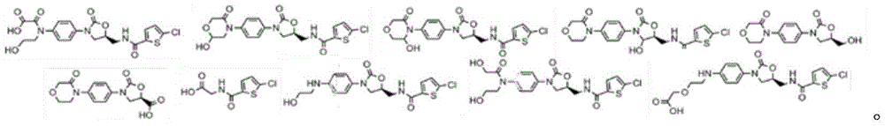
Applications Claiming Priority (7)
| Application Number | Priority Date | Filing Date | Title |
|---|---|---|---|
| US201862742284P | 2018-10-06 | 2018-10-06 | |
| US62/742,284 | 2018-10-06 | ||
| US201862771117P | 2018-11-25 | 2018-11-25 | |
| US62/771,117 | 2018-11-25 | ||
| US201862780288P | 2018-12-16 | 2018-12-16 | |
| US62/780,288 | 2018-12-16 | ||
| PCT/US2019/045429 WO2020072128A1 (en) | 2018-10-06 | 2019-08-07 | Methods and apparatus for a wearable electronic digital therapeutic device |
Publications (1)
| Publication Number | Publication Date |
|---|---|
| CN113226448A true CN113226448A (en) | 2021-08-06 |
Family
ID=70054729
Family Applications (1)
| Application Number | Title | Priority Date | Filing Date |
|---|---|---|---|
| CN201980081061.6A Pending CN113226448A (en) | 2018-10-06 | 2019-08-07 | Method and apparatus for a wearable electronic digital treatment device |
Country Status (3)
| Country | Link |
|---|---|
| US (1) | US20210244941A1 (en) |
| CN (1) | CN113226448A (en) |
| WO (1) | WO2020072128A1 (en) |
Cited By (7)
| Publication number | Priority date | Publication date | Assignee | Title |
|---|---|---|---|---|
| CN114271799A (en) * | 2021-12-21 | 2022-04-05 | 江苏省人民医院(南京医科大学第一附属医院) | A Cardiovascular Detection Method Based on Intelligent Terminal |
| CN114974507A (en) * | 2022-05-18 | 2022-08-30 | 河海大学 | Varicosity rehabilitation training system and method based on virtual reality game |
| CN115633943A (en) * | 2022-11-09 | 2023-01-24 | 东北大学 | Lower extremity venous thrombosis early warning and evaluation system based on multimodal continuous monitoring signals |
| CN115778406A (en) * | 2022-12-23 | 2023-03-14 | 深圳市应和脑科学有限公司 | Electromyographic signal acquisition device |
| TWI847384B (en) * | 2022-11-23 | 2024-07-01 | 國立清華大學 | Thermoelectric driving wearable system |
| CN120236771A (en) * | 2025-05-29 | 2025-07-01 | 厦门大学附属心血管病医院(厦门市心脏中心) | A rehabilitation management system for patients with peripheral arterial disease based on the whole process |
| US12482208B2 (en) | 2023-05-30 | 2025-11-25 | Snap Inc. | Mirroring 3D assets for virtual experiences |
Families Citing this family (23)
| Publication number | Priority date | Publication date | Assignee | Title |
|---|---|---|---|---|
| US11633594B2 (en) * | 2018-10-23 | 2023-04-25 | Biowave Corporation | Electrotherapy and neurostimulation medical device apparatus and method |
| IL268796B2 (en) * | 2019-08-20 | 2024-02-01 | Ainnotech A N Ltd | Machine and system for drug distribution |
| US11571515B2 (en) | 2019-08-29 | 2023-02-07 | Medtronic Minimed, Inc. | Controlling medical device operation and features based on detected patient sleeping status |
| CN114787932A (en) | 2019-12-13 | 2022-07-22 | 美敦力迷你迈德公司 | Method and system for training a mathematical model of a user based on data received from a discrete insulin therapy system |
| US11938301B2 (en) | 2019-12-13 | 2024-03-26 | Medtronic Minimed, Inc. | Controlling medication delivery system operation and features based on automatically detected muscular movements |
| US11839759B2 (en) | 2020-09-21 | 2023-12-12 | Neuro20 Technologies Corp. | Systems and methods for managed training and rehabilitation via electrical stimulation |
| TR202022824A2 (en) * | 2020-12-31 | 2021-04-21 | Atatuerk Ueniversitesi Rektoerluegue Bilimsel Arastirma Projeleri Bap Koordinasyon Birimi | Smart panty system for varicocele patients |
| US20220313982A1 (en) * | 2021-04-05 | 2022-10-06 | Stephan Ryan Martinez | Wearable device to ameliorate pain |
| WO2022244937A1 (en) * | 2021-05-18 | 2022-11-24 | 주식회사 코어무브먼트 | Electrical stimulation system usable underwater |
| US12138057B2 (en) * | 2021-06-04 | 2024-11-12 | Endosure, Inc. | Method and system for monitoring internal bodily disorders by detecting and analyzing tissue frequencies |
| US20220395685A1 (en) * | 2021-06-11 | 2022-12-15 | University Of Houston System | Devices, systems and methods of mapping neuromuscular junctions for botulinum toxin injections |
| WO2023278579A1 (en) * | 2021-06-29 | 2023-01-05 | GE Precision Healthcare LLC | Systems and methods for disposable sensors |
| EP4433148A4 (en) | 2021-11-15 | 2025-05-14 | Neuro20 Technologies Corp. | Systems and methods for promoting tissue health through electrical stimulation |
| US20230181110A1 (en) * | 2021-12-15 | 2023-06-15 | Scoggleberries Design Llc | Methods and apparatus for a baby monitoring garment |
| DE102021006294A1 (en) | 2021-12-21 | 2023-06-22 | Johann Wolfgang Reiner Grünter | Portable vital meter |
| US20230301598A1 (en) * | 2022-03-25 | 2023-09-28 | At&T Intellectual Property I, L.P. | System and method for improving gating and motor skills of patients diagnosed with neurological disorders |
| US20250229080A1 (en) * | 2022-04-06 | 2025-07-17 | John James Daniels | Wearable electronic for digital healthcare |
| KR102855805B1 (en) * | 2022-04-22 | 2025-09-05 | 주식회사 바디프랜드 | A massage apparatus providing a massage mode to stretch the user's buttocks |
| CN115349876B (en) * | 2022-09-22 | 2023-09-15 | 北京市神经外科研究所 | Myoelectricity acquisition system |
| EP4356952A1 (en) * | 2022-10-19 | 2024-04-24 | ETH Zürich | System for producing somatotopic sensations using transcutaneous electrical nerve stimulation (tens) |
| KR20250062946A (en) * | 2023-10-31 | 2025-05-08 | 주식회사 코어무브먼트 | Electrical muscle stimulation system and electrical muscle stimulation method capable of implementing rolling massage effect by individual channel control |
| GB2638972A (en) * | 2024-03-04 | 2025-09-10 | Point Fit Tech Limited | Body fluid-based biological detection apparatus and method |
| CN119257576B (en) * | 2024-11-26 | 2025-06-13 | 河北军涛科技有限公司 | A wearable intelligent training device with physiological detection function |
Citations (11)
| Publication number | Priority date | Publication date | Assignee | Title |
|---|---|---|---|---|
| JP2002224227A (en) * | 2001-01-31 | 2002-08-13 | Yasunobu Handa | Economy class syndrome preventing device |
| US7539724B1 (en) * | 2002-06-04 | 2009-05-26 | Rockwell Automation Technologies, Inc. | Instant messaging for event notification and exchanging data in an industrial controller environment |
| US20100106044A1 (en) * | 2008-10-27 | 2010-04-29 | Michael Linderman | EMG measured during controlled hand movement for biometric analysis, medical diagnosis and related analysis |
| US20100198314A1 (en) * | 2009-01-30 | 2010-08-05 | Abbott Diabetes Care, Inc. | Computerized Determination of Insulin Pump Therapy Parameters Using Real Time and Retrospective Data Processing |
| US20110098761A1 (en) * | 2009-10-23 | 2011-04-28 | Medtronic Cryocath Lp | Method and system for preventing nerve injury during a medical procedure |
| US20150024381A1 (en) * | 2012-03-07 | 2015-01-22 | University Of Delaware | Detecting and quantifying cryptic hiv replication |
| WO2015102624A2 (en) * | 2013-12-31 | 2015-07-09 | Joshua Cornelius Burris | Treatments for venous conditions |
| WO2016125087A1 (en) * | 2015-02-04 | 2016-08-11 | Siano Mobile Silicon Ltd. | Deep vein thrombosis prevention |
| CN107809943A (en) * | 2015-04-02 | 2018-03-16 | 豪夫迈·罗氏有限公司 | For analyzing from the method and system for suffering from the glucose data that person with diabetes measures |
| WO2018098046A2 (en) * | 2016-11-25 | 2018-05-31 | Kinaptic, LLC | Haptic human machine interface and wearable electronics methods and apparatus |
| US20180229041A1 (en) * | 2017-02-14 | 2018-08-16 | Verily Life Sciences Llc | Optimizing neuromodulation stimulation parameters using blood parameter sensing |
Family Cites Families (12)
| Publication number | Priority date | Publication date | Assignee | Title |
|---|---|---|---|---|
| US7597677B2 (en) * | 2001-11-16 | 2009-10-06 | National Quality Care, Inc. | Wearable ultrafiltration device |
| US20060036619A1 (en) * | 2004-08-09 | 2006-02-16 | Oren Fuerst | Method for accessing and analyzing medically related information from multiple sources collected into one or more databases for deriving illness probability and/or for generating alerts for the detection of emergency events relating to disease management including HIV and SARS, and for syndromic surveillance of infectious disease and for predicting risk of adverse events to one or more drugs |
| US7558765B2 (en) * | 2005-01-14 | 2009-07-07 | Ultra-Scan Corporation | Multimodal fusion decision logic system using copula model |
| US20070123754A1 (en) * | 2005-11-29 | 2007-05-31 | Cuddihy Paul E | Non-encumbering, substantially continuous patient daily activity data measurement for indication of patient condition change for access by remote caregiver |
| US8712509B2 (en) * | 2008-07-25 | 2014-04-29 | Medtronic, Inc. | Virtual physician acute myocardial infarction detection system and method |
| AU2011353038B2 (en) * | 2010-12-29 | 2015-01-22 | Cardiac Pacemakers, Inc. | Neuro cardiac therapy using electrical impedance |
| US20160128638A1 (en) * | 2014-11-10 | 2016-05-12 | Bloom Technologies NV | System and method for detecting and quantifying deviations from physiological signals normality |
| US11164596B2 (en) * | 2016-02-25 | 2021-11-02 | Samsung Electronics Co., Ltd. | Sensor assisted evaluation of health and rehabilitation |
| US20180070870A1 (en) * | 2016-09-09 | 2018-03-15 | The Board Of Trustees Of The Leland Stanford Junior University | Autonomous Sweat Extraction and Analysis Using a Fully-Integrated Wearable Platform |
| WO2018057616A1 (en) * | 2016-09-21 | 2018-03-29 | Rejuvenan Global Health, Inc. | Interactive computing system to generate customized preventive health information based on an individual's biomarkers |
| US20180365385A1 (en) * | 2017-06-16 | 2018-12-20 | University Hospitals Of Cleveland | Monitoring and evaluating patient reactions to medications |
| WO2019226581A1 (en) * | 2018-05-25 | 2019-11-28 | Zoll Medical Corporation | Wearable cardiac device to monitor physiological response to activity |
-
2019
- 2019-08-07 CN CN201980081061.6A patent/CN113226448A/en active Pending
- 2019-08-07 WO PCT/US2019/045429 patent/WO2020072128A1/en not_active Ceased
-
2021
- 2021-03-15 US US17/201,091 patent/US20210244941A1/en active Pending
Patent Citations (11)
| Publication number | Priority date | Publication date | Assignee | Title |
|---|---|---|---|---|
| JP2002224227A (en) * | 2001-01-31 | 2002-08-13 | Yasunobu Handa | Economy class syndrome preventing device |
| US7539724B1 (en) * | 2002-06-04 | 2009-05-26 | Rockwell Automation Technologies, Inc. | Instant messaging for event notification and exchanging data in an industrial controller environment |
| US20100106044A1 (en) * | 2008-10-27 | 2010-04-29 | Michael Linderman | EMG measured during controlled hand movement for biometric analysis, medical diagnosis and related analysis |
| US20100198314A1 (en) * | 2009-01-30 | 2010-08-05 | Abbott Diabetes Care, Inc. | Computerized Determination of Insulin Pump Therapy Parameters Using Real Time and Retrospective Data Processing |
| US20110098761A1 (en) * | 2009-10-23 | 2011-04-28 | Medtronic Cryocath Lp | Method and system for preventing nerve injury during a medical procedure |
| US20150024381A1 (en) * | 2012-03-07 | 2015-01-22 | University Of Delaware | Detecting and quantifying cryptic hiv replication |
| WO2015102624A2 (en) * | 2013-12-31 | 2015-07-09 | Joshua Cornelius Burris | Treatments for venous conditions |
| WO2016125087A1 (en) * | 2015-02-04 | 2016-08-11 | Siano Mobile Silicon Ltd. | Deep vein thrombosis prevention |
| CN107809943A (en) * | 2015-04-02 | 2018-03-16 | 豪夫迈·罗氏有限公司 | For analyzing from the method and system for suffering from the glucose data that person with diabetes measures |
| WO2018098046A2 (en) * | 2016-11-25 | 2018-05-31 | Kinaptic, LLC | Haptic human machine interface and wearable electronics methods and apparatus |
| US20180229041A1 (en) * | 2017-02-14 | 2018-08-16 | Verily Life Sciences Llc | Optimizing neuromodulation stimulation parameters using blood parameter sensing |
Cited By (9)
| Publication number | Priority date | Publication date | Assignee | Title |
|---|---|---|---|---|
| CN114271799A (en) * | 2021-12-21 | 2022-04-05 | 江苏省人民医院(南京医科大学第一附属医院) | A Cardiovascular Detection Method Based on Intelligent Terminal |
| CN114974507A (en) * | 2022-05-18 | 2022-08-30 | 河海大学 | Varicosity rehabilitation training system and method based on virtual reality game |
| CN115633943A (en) * | 2022-11-09 | 2023-01-24 | 东北大学 | Lower extremity venous thrombosis early warning and evaluation system based on multimodal continuous monitoring signals |
| CN115633943B (en) * | 2022-11-09 | 2024-06-28 | 东北大学 | Lower extremity venous thrombosis early warning evaluation system based on multimodal continuous monitoring signals |
| TWI847384B (en) * | 2022-11-23 | 2024-07-01 | 國立清華大學 | Thermoelectric driving wearable system |
| US12324908B2 (en) | 2022-11-23 | 2025-06-10 | National Tsing Hua University | Thermoelectric driving wearable system |
| CN115778406A (en) * | 2022-12-23 | 2023-03-14 | 深圳市应和脑科学有限公司 | Electromyographic signal acquisition device |
| US12482208B2 (en) | 2023-05-30 | 2025-11-25 | Snap Inc. | Mirroring 3D assets for virtual experiences |
| CN120236771A (en) * | 2025-05-29 | 2025-07-01 | 厦门大学附属心血管病医院(厦门市心脏中心) | A rehabilitation management system for patients with peripheral arterial disease based on the whole process |
Also Published As
| Publication number | Publication date |
|---|---|
| WO2020072128A1 (en) | 2020-04-09 |
| US20210244941A1 (en) | 2021-08-12 |
Similar Documents
| Publication | Publication Date | Title |
|---|---|---|
| US20210244941A1 (en) | Methods and apparatus for a wearable electronic digital therapeutic device | |
| US12193842B2 (en) | Modular physiologic monitoring systems, kits, and methods | |
| US12376782B2 (en) | Modular physiologic monitoring systems, kits, and methods | |
| Teng et al. | Wearable medical systems for p-health | |
| US9967040B2 (en) | Patch system for in-situ therapeutic treatment | |
| AU2015296139B2 (en) | Modular physiologic monitoring systems, kits, and methods | |
| KR20160088882A (en) | Conformal sensor systems for sensing and analysis of cardiac activity | |
| US20250229080A1 (en) | Wearable electronic for digital healthcare | |
| Nag et al. | Wearable electronics sensors: current status and future opportunities | |
| Lakshmi et al. | Smart Health Monitoring System For The Elderly | |
| Gui et al. | Latest progresses in developing wearable monitoring and therapy systems for managing chronic diseases | |
| Rubi et al. | Wearable health monitoring systems using IoMT | |
| Fariah et al. | Application of Wearable Devices in the Medical Domain | |
| Andreoni et al. | Example of clinical applications of wearable monitoring systems | |
| Gupta et al. | 4 IoT in Smart | |
| VS et al. | Recent Trends in Wearable Sensor Technology for E-Health Monitoring | |
| Linh et al. | Seeing in Body Using Wearable Electronics | |
| Scott | Wrist Worn Device to Aid the Elderly to Age in Place |
Legal Events
| Date | Code | Title | Description |
|---|---|---|---|
| PB01 | Publication | ||
| PB01 | Publication | ||
| SE01 | Entry into force of request for substantive examination | ||
| SE01 | Entry into force of request for substantive examination | ||
| WD01 | Invention patent application deemed withdrawn after publication | ||
| WD01 | Invention patent application deemed withdrawn after publication |
Application publication date: 20210806 |