CN113226212A - Guide and support for craniofacial compression - Google Patents
Guide and support for craniofacial compression Download PDFInfo
- Publication number
- CN113226212A CN113226212A CN201980086935.7A CN201980086935A CN113226212A CN 113226212 A CN113226212 A CN 113226212A CN 201980086935 A CN201980086935 A CN 201980086935A CN 113226212 A CN113226212 A CN 113226212A
- Authority
- CN
- China
- Prior art keywords
- support
- craniofacial
- guide
- needle
- ring
- Prior art date
- Legal status (The legal status is an assumption and is not a legal conclusion. Google has not performed a legal analysis and makes no representation as to the accuracy of the status listed.)
- Granted
Links
Images


Classifications
-
- A—HUMAN NECESSITIES
- A61—MEDICAL OR VETERINARY SCIENCE; HYGIENE
- A61B—DIAGNOSIS; SURGERY; IDENTIFICATION
- A61B90/00—Instruments, implements or accessories specially adapted for surgery or diagnosis and not covered by any of the groups A61B1/00 - A61B50/00, e.g. for luxation treatment or for protecting wound edges
- A61B90/10—Instruments, implements or accessories specially adapted for surgery or diagnosis and not covered by any of the groups A61B1/00 - A61B50/00, e.g. for luxation treatment or for protecting wound edges for stereotaxic surgery, e.g. frame-based stereotaxis
- A61B90/11—Instruments, implements or accessories specially adapted for surgery or diagnosis and not covered by any of the groups A61B1/00 - A61B50/00, e.g. for luxation treatment or for protecting wound edges for stereotaxic surgery, e.g. frame-based stereotaxis with guides for needles or instruments, e.g. arcuate slides or ball joints
-
- A—HUMAN NECESSITIES
- A61—MEDICAL OR VETERINARY SCIENCE; HYGIENE
- A61B—DIAGNOSIS; SURGERY; IDENTIFICATION
- A61B17/00—Surgical instruments, devices or methods
- A61B17/34—Trocars; Puncturing needles
-
- A—HUMAN NECESSITIES
- A61—MEDICAL OR VETERINARY SCIENCE; HYGIENE
- A61B—DIAGNOSIS; SURGERY; IDENTIFICATION
- A61B90/00—Instruments, implements or accessories specially adapted for surgery or diagnosis and not covered by any of the groups A61B1/00 - A61B50/00, e.g. for luxation treatment or for protecting wound edges
- A61B90/10—Instruments, implements or accessories specially adapted for surgery or diagnosis and not covered by any of the groups A61B1/00 - A61B50/00, e.g. for luxation treatment or for protecting wound edges for stereotaxic surgery, e.g. frame-based stereotaxis
- A61B90/14—Fixators for body parts, e.g. skull clamps; Constructional details of fixators, e.g. pins
-
- A—HUMAN NECESSITIES
- A61—MEDICAL OR VETERINARY SCIENCE; HYGIENE
- A61B—DIAGNOSIS; SURGERY; IDENTIFICATION
- A61B90/00—Instruments, implements or accessories specially adapted for surgery or diagnosis and not covered by any of the groups A61B1/00 - A61B50/00, e.g. for luxation treatment or for protecting wound edges
- A61B90/50—Supports for surgical instruments, e.g. articulated arms
- A61B2090/502—Headgear, e.g. helmet, spectacles
Landscapes
- Health & Medical Sciences (AREA)
- Surgery (AREA)
- Life Sciences & Earth Sciences (AREA)
- Medical Informatics (AREA)
- Animal Behavior & Ethology (AREA)
- Engineering & Computer Science (AREA)
- Biomedical Technology (AREA)
- Heart & Thoracic Surgery (AREA)
- Pathology (AREA)
- Molecular Biology (AREA)
- Nuclear Medicine, Radiotherapy & Molecular Imaging (AREA)
- General Health & Medical Sciences (AREA)
- Public Health (AREA)
- Veterinary Medicine (AREA)
- Oral & Maxillofacial Surgery (AREA)
- Neurosurgery (AREA)
- Surgical Instruments (AREA)
Abstract
本发明用于适合于使用器械进行手术和诊断的器械和装置领域。具体而言,它涉及一种能够在颅面区域中穿刺特定解剖结构的装置。该装置包括可调节头带形式的支撑框架,可适应用户的解剖结构,具有两个臂的球体,将定位紧固件固定在用户的面部或颅骨上,通过使用螺钉或环向特定位置施加压力,允许在臂的铰链上自由移动。
The present invention is used in the field of instruments and devices suitable for using instruments for surgery and diagnosis. Specifically, it relates to a device capable of puncturing specific anatomical structures in the craniofacial region. The device includes a support frame in the form of an adjustable headband that adapts to the user's anatomy, a sphere with two arms that secures locating fasteners to the user's face or skull, applying pressure to specific locations through the use of screws or loops , allowing free movement on the hinge of the arm.
Description
Technical Field
The invention is applicable in the field of instruments and devices suitable for surgery and diagnosis. In particular, it relates to a device for enabling penetration of specific anatomical structures of a cranial region. The device includes a support frame in the form of an adjustable headband that can accommodate the anatomy of the user, a sphere with two arms, a placement fastener that is secured to the face or skull of the user, and a screw or ring that allows free movement on the hinge of the arms by applying pressure to a specific location.
Background
Puncturing devices in various fields pose challenges to healthcare professionals because of the constant risk of damaging adjacent structures during surgery, since it is performed manually, with or without success depending on the skill of the user. The use of the device can introduce factors such as difficulty in locating the precise puncture point during the procedure and the stability, orientation and precision of the needle. Also, existing devices are not equipped with mechanisms that allow the needle to remain in place while establishing a trajectory that locates the target structure.
The most advanced devices available include solutions for fixation and adaptation during surgery and penetration by fixation mechanisms using screws, or solutions that do not allow for a progressive approach. However, there are no known solutions that can be effectively and safely applied to the puncture of facial structures without injuring the user, or can be firmly fixed to irregular areas of the face, or allow work area grading, or allow for a margin of variation in the degree of allowance.
The known prior art US009901400B2 "stereo positioning device and method" allows body regions such as the skull to be accessed. The precursor has an accessory showing the screw (103) adjusted to fit the body surface without any other type of support and no other mechanism for attachment to the facial area. Facial puncture is not possible because the face portion has an irregular surface and the precursor body does not conform closely to establish needle or cannula access without damaging the face portion, because this feature is similar to that of the precursor body. Furthermore, there is limited room available to the user in terms of mobility of the access device, as this depends on the insertion depth of the screw (103). The present invention does not have a screw assembly method that could harm the user because it is not feasible to insert screws into the face when facial punctures are involved. Unlike the solutions known from the prior art, the present invention proposes a new solution for the assembly of craniofacial functional devices, without the need for inserting screws and fitting tightly to irregular parts; whereas the precursor does not have these features.
The patent US8414597B2 "apaarato PARA APOYAR a AJUSTE qualrljrgico (device for supporting surgical adjustments)" comprises a support which allows a higher precision in the procedures performed on different parts of the body. The precursor is provided with a plurality of modes of use; however, all of these have in common that they are adhered or attached to the surface of interest (150), mainly the skull, by screws or other mechanisms that allow their proper connection. However, using this system, it is challenging to try to properly secure the support to the face without significantly harming the person, in order to safely access the target area. Although it is mentioned in the predecessor patent that the frame supports (342), (344) and (346) may be screws, bolts, coils or other anchoring mechanisms to allow secure fixation of the skull base of the subject, which is round and flat, it is not possible to fix it on irregular faces, nor is it possible to do without screws. The precursor patent No. US8414597B2 may not be safely applied to facial puncture, otherwise it may cause significant facial damage to a person, requiring major modifications to its design to enable its use.
Known prior art patent US20100298846a1 "plaform querurgica UNIVERSAL surgical platform", designed for the field of stereotactic neurosurgery, means that its design is mainly suitable for performing cranial punctures, which require the use of a method distinct from facial punctures. This technique has a "surgical platform" inside which a perforated sphere is envisaged through which the probe passes and is surrounded by a set of rings, which are allowed to rotate through 360 ° until the activator located on the outer ring is pressed. In order to allow the probe to pass safely through the sphere, the ring, which acts as a stabilizer, is connected to a number of components that form a mechanical support, the bottom fixture being mounted on the patient's head. This technique does not allow for varying the diameter of the ring, thereby preventing simultaneous adjustment of the puncture angle and site. In the case of the new invention, the adaptation of the new device is made by varying the ring diameter and the puncturing is applied in a variable working area determined by the variation of the ring diameter, which also allows a greater freedom of different puncturing strategies. The new patent also allows the use of probes of different sizes, since the perforation of the sphere has a variable diameter and it is possible to position the working area of the work surface by means of the nozzles on the support arch. Both can be attached or fixed to the face or skull without piercing the skin and ensuring that the device is fixed.
Known devices most similar to the proposed invention cannot be used to perform facial punctures because their use of screw fixation or attachment can result in facial or cranial injuries in order to be able to attach securely. The present invention proposes a new solution for performing craniofacial penetration, which is unknown in the prior art and, unlike known solutions for mounting craniofacial devices without screws, has a universal needle movement and staging work area, has adaptable fixed positions to reach the required configuration, and allows efficient and safe penetration by the operator.
Disclosure of Invention
The craniofacial puncture guide bracket is an instrument for puncturing different craniofacial structures and is also an auxiliary teaching and training tool for improving the craniofacial puncture technology. It can also be used in other types of facial surgery where it is necessary to firmly fix the instrument at a specific point.
In particular, the present invention is an apparatus procedure that can be used to improve the performance of facial punctures by using supports that adapt to the anatomy of the user and adjust to provide stability and accuracy to the healthcare professional when performing the craniocerebral puncture. This improvement is reflected in a reduced need for further intervention by the user, a shorter recovery time, more effective results, and a shorter time between interventions, which will ultimately enable healthcare professionals to perform under the concept of safe surgery, reducing errors and not causing harm to the user.
The device provides support for lancing on different areas of the face and skull. It has an arch-like structure that fits the head, can accommodate the anatomy of the patient, and additional support allows the needle to be placed at different angles in the posterior, anterior, and lateral regions of the face. This allows safe penetration of different structures avoiding damage to the proximal structure. In addition to modifying the angle, the centering ring of the needle insertion also allows for free adjustment of the puncture site after adjustment of the entire support mechanism.
Drawings
The drawings illustrate the following suggested ranges for guiding and supporting craniofacial penetration:
brief description of the drawings:
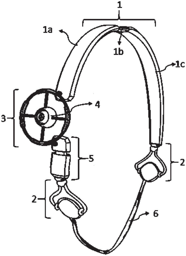
FIG. 1 shows a perspective view of a guide and a bracket for performing craniofacial penetration.
Fig. 2 shows mating images of a guide and support for craniofacial penetration of a user.
Fig. 3 shows a front view of a guide and support for performing craniofacial puncture and major portions thereof.
Fig. 4 shows an image of a secure coupling that allows the headband to be mounted to the skull and face of a user.
FIG. 5 shows an image of an adjustable mount supporting a ring of a needle holder.
Figure 6 shows a front view of the variable diameter ring supporting the needle carrier.
FIG. 7 shows an image of a needle holder with a mechanism to secure the unsecured spherical central support.
FIG. 8 shows an image of a needle holder with a mechanism to secure a spherical central support.
Fig. 9 shows an image of an alternative mechanism for securing the needle.
Detailed Description
The present invention is a device for craniofacial specific anatomical penetration comprising a headband (1) consisting of one arch (1a), the arch (1a) being connected to another arch (1c) by an upper adjustable tie (1b), which allows to modify the distance between one arch (1a) and the other arch (1c) to fit the anatomy of the user.
As shown in fig. 4, a fastener coupler (2) is attached to the end of the arch (1c) in fig. 1 to securely fix the headband (1) to the skull bone, wherein a female piece (2a) connected to its internal ball (2c) is incorporated into the fastener coupler (2) to enable the ball (2c) to rotate freely. The ball (2c) has at one end a rod, not shown, which locks with a snap ring (2b) in the inner surface of the female part (2a), whereby the snap ring (2b) when pressed secures the ball (2c) in the desired position on the surface of the ball (2c) inside the female part (2 a).
At the other end of the ball (2c) there are two arms (2d) for securing a fastener (2f), the fastener (2f) positioning its surface on the face or skull of the user by applying pressure to provide support. The fastening elements (2f) are fixed in a specific position together with the sliding blocks (2e) and, when they are not adjusted, they allow the fastening elements (2f) to move freely on the ends of the arms (2d), acting as hinges for the fastening elements (2 f).
At the end of the arch (1a) there is a ring (3) of variable diameter, which is connected to the end of the arch (1a) of the headband (1), and on the upper edge of which there is an adjustable base (3 a); at the lower edge, the variable diameter ring (3) is connected to a side plate portion (5) with an adjustable seat (3a), wherein the adjustable seat (3a) of the edge allows to modify the distance and to apply pressure between the variable diameter ring (3) and the user.
The side plate portion (5) comprises a lower plate (5c) and an upper plate (5a) which are supported and retained by means of adjustable side tie rods (5b) which allow to modify the distance between the lower plate (5c) and the upper plate (5 a).
The variable diameter ring (3) comprises a frame, which in different variants of the invention can be circular, triangular, square or polygonal, intended to be performed at a critical point of the skull according to the anatomical structure in which the intervention is to be performed. The reducing ring (3) is connected with the concentric needle frame (4) through a scale hinge (3g), wherein the needle frame (4) consists of an outer rotating needle frame (4a) and a central spherical support (4b) and can rotate 360 degrees in the outer needle frame (4 a).
The adjustable base (3a) consists of two hollow cylinders (3a.1) and (3a.3) connected by a rod (3a.2) crossing them, allowing the length of the base to be adjusted and fixed in a specific position using a screw portion (3 a.4). Furthermore, there is a support (3a.5) connected to the headband (1) and the upper support (5 a).
As shown in fig. 6, each adjustable seat (3a) is in turn connected to several hollow cylinders (3b) and (3c), wherein an elastic ring (3f) passes through the hollow cylinders (3b), which together form a variable diameter ring (3) which allows to increase the working area for the movement of the needle. Once the desired working area diameter is established within the variable diameter ring (3), the hollow cylinder (3c) is fixed by simultaneously pressing the opposing snap rings (3 e).
Each hollow cylinder (3c) has a hinge (3g) connecting the variable diameter ring (3) with the outer needle carrier (4 a). These hinges (3g) are adjustable straps that increase the distance between the outer needle carrier and the variable diameter ring (3).
The rotating outer needle carrier (4a) comprises another outer structure connected to a hinge (3 g). This configuration provides rigidity and stability to the rotating variable diameter ring (3) and can be moved in different directions within the variable diameter ring (3) by simultaneously pressing the opposing snap rings (3d) to secure the needle at the desired point.
Fig. 7 and 8 show the spherical central support (4b) from different angles of its range of motion. The spherical central support (4b) is connected to the outer needle carrier (4a) and allows an internal rotation of 360 ° to change the direction of the needle to perform the puncture; it has a snap ring (4c) which, when depressed, activates a wedge (4d) to hold a spherical central support (4b) in place.
The needle holder (4) has three adjustable supports in the centre (4e) and the diameter of the centre through which the needle passes can be varied so that it is adjusted to the size of the needle using a knob (4f) which, when rotated, progressively opens or closes the position of the space holding needle support (4 e).
Fig. 9 shows one way of the invention, with an alternative mechanism for fixing the needle with the tube (4h) filled with elastic material inside, which provides support and stability for the needle, but at the same time allows it to slide clamping the needle head through a small central channel (4i), making puncture possible.
Also, at the lower end of the lower plate (5c) there is a fastener coupling (2) where it connects to the female part (2a) of the ball (2 c).
The fastener (2f) is connected to another opposing fastener (2f) by a detachable adjustable strap (6) to secure the headband (1) to a user.
In light of the above detailed drawings, the external design presented in the drawings does not constitute a limitation on alternative forms of design for performing guidance and support of craniofacial puncture, so long as it does not conflict with the objectives described herein.
Claims (10)
Applications Claiming Priority (1)
| Application Number | Priority Date | Filing Date | Title |
|---|---|---|---|
| PCT/IB2019/053356 WO2020217086A1 (en) | 2019-04-24 | 2019-04-24 | Guide and support for performing craniofacial punctions |
Publications (2)
| Publication Number | Publication Date |
|---|---|
| CN113226212A true CN113226212A (en) | 2021-08-06 |
| CN113226212B CN113226212B (en) | 2024-03-19 |
Family
ID=72941562
Family Applications (1)
| Application Number | Title | Priority Date | Filing Date |
|---|---|---|---|
| CN201980086935.7A Active CN113226212B (en) | 2019-04-24 | 2019-04-24 | Guides and supports for craniofacial compressions |
Country Status (3)
| Country | Link |
|---|---|
| US (1) | US12011322B2 (en) |
| CN (1) | CN113226212B (en) |
| WO (1) | WO2020217086A1 (en) |
Families Citing this family (2)
| Publication number | Priority date | Publication date | Assignee | Title |
|---|---|---|---|---|
| CN113288366B (en) * | 2021-06-09 | 2023-12-01 | 黄树其 | Department of neurology cerebral vessels intervenes puncture positioner |
| CN114224454B (en) * | 2022-01-20 | 2024-09-20 | 池州市人民医院 | A visual cricothyroid membrane puncture instrument |
Citations (17)
| Publication number | Priority date | Publication date | Assignee | Title |
|---|---|---|---|---|
| US4695250A (en) * | 1986-06-23 | 1987-09-22 | Fairdale Orthodontic Company | Breakaway orthodontic face bow appliance |
| CN2265199Y (en) * | 1994-10-17 | 1997-10-22 | 林延丽 | Multi-function ultrasonic leading puncture device |
| CN2922803Y (en) * | 2006-04-27 | 2007-07-18 | 石海祥 | Cerebral hemorrhage puncturing navigation positioner |
| CN201279141Y (en) * | 2008-11-04 | 2009-07-29 | 袁相晋 | CT led skull puncture solid spacer |
| KR20110034423A (en) * | 2009-09-28 | 2011-04-05 | 배선관 | Pipe fixture |
| CN102090932A (en) * | 2011-03-22 | 2011-06-15 | 上海交通大学 | CT guided lung puncture positioning instrument |
| CN102245250A (en) * | 2008-12-10 | 2011-11-16 | 雷斯梅德有限公司 | headband for mask |
| EP2666414A1 (en) * | 2012-05-22 | 2013-11-27 | Godert Zijlstra | Ultrasound device for guided puncture of vascular access |
| US20160193009A1 (en) * | 2011-08-22 | 2016-07-07 | Visualase, Inc. | Stereotactic Access Devices And Methods |
| CN205903270U (en) * | 2016-06-27 | 2017-01-25 | 李蕊 | B ultrasonic probe fixing device |
| CN106456275A (en) * | 2014-01-23 | 2017-02-22 | 视觉激光股份有限公司 | Stereotactic access devices and methods |
| US20170296295A1 (en) * | 2014-10-28 | 2017-10-19 | Timothy Andrew WAGNER | Adjustable headpiece with anatomical markers and methods of use thereof |
| CN206630630U (en) * | 2016-12-29 | 2017-11-14 | 董航 | A kind of blood internal medicine sting device |
| CN107485480A (en) * | 2017-10-10 | 2017-12-19 | 曹茂娟 | One kind is stable to puncture fixing device |
| CN207693658U (en) * | 2017-06-16 | 2018-08-07 | 薛宇龙 | A kind of positioning device for intracranial hematoma chamber drainage |
| CN109091214A (en) * | 2018-09-29 | 2018-12-28 | 刘国军 | Intracranial hematoma Minimally invasive puncture Needle localization system and accurate stereotaxic apparatus |
| CN109646124A (en) * | 2019-02-15 | 2019-04-19 | 郑州大学第附属医院 | Magnetic resonance compatible formula cranium brain solid fixes device |
Family Cites Families (2)
| Publication number | Priority date | Publication date | Assignee | Title |
|---|---|---|---|---|
| WO2007056458A2 (en) | 2005-11-07 | 2007-05-18 | Vanderbilt University | Adjustable universal surgical platform |
| US8414597B2 (en) | 2005-11-07 | 2013-04-09 | Vanderbilt University | Apparatus for supporting an adjustable surgical platform |
-
2019
- 2019-04-24 CN CN201980086935.7A patent/CN113226212B/en active Active
- 2019-04-24 US US17/416,588 patent/US12011322B2/en active Active
- 2019-04-24 WO PCT/IB2019/053356 patent/WO2020217086A1/en not_active Ceased
Patent Citations (17)
| Publication number | Priority date | Publication date | Assignee | Title |
|---|---|---|---|---|
| US4695250A (en) * | 1986-06-23 | 1987-09-22 | Fairdale Orthodontic Company | Breakaway orthodontic face bow appliance |
| CN2265199Y (en) * | 1994-10-17 | 1997-10-22 | 林延丽 | Multi-function ultrasonic leading puncture device |
| CN2922803Y (en) * | 2006-04-27 | 2007-07-18 | 石海祥 | Cerebral hemorrhage puncturing navigation positioner |
| CN201279141Y (en) * | 2008-11-04 | 2009-07-29 | 袁相晋 | CT led skull puncture solid spacer |
| CN102245250A (en) * | 2008-12-10 | 2011-11-16 | 雷斯梅德有限公司 | headband for mask |
| KR20110034423A (en) * | 2009-09-28 | 2011-04-05 | 배선관 | Pipe fixture |
| CN102090932A (en) * | 2011-03-22 | 2011-06-15 | 上海交通大学 | CT guided lung puncture positioning instrument |
| US20160193009A1 (en) * | 2011-08-22 | 2016-07-07 | Visualase, Inc. | Stereotactic Access Devices And Methods |
| EP2666414A1 (en) * | 2012-05-22 | 2013-11-27 | Godert Zijlstra | Ultrasound device for guided puncture of vascular access |
| CN106456275A (en) * | 2014-01-23 | 2017-02-22 | 视觉激光股份有限公司 | Stereotactic access devices and methods |
| US20170296295A1 (en) * | 2014-10-28 | 2017-10-19 | Timothy Andrew WAGNER | Adjustable headpiece with anatomical markers and methods of use thereof |
| CN205903270U (en) * | 2016-06-27 | 2017-01-25 | 李蕊 | B ultrasonic probe fixing device |
| CN206630630U (en) * | 2016-12-29 | 2017-11-14 | 董航 | A kind of blood internal medicine sting device |
| CN207693658U (en) * | 2017-06-16 | 2018-08-07 | 薛宇龙 | A kind of positioning device for intracranial hematoma chamber drainage |
| CN107485480A (en) * | 2017-10-10 | 2017-12-19 | 曹茂娟 | One kind is stable to puncture fixing device |
| CN109091214A (en) * | 2018-09-29 | 2018-12-28 | 刘国军 | Intracranial hematoma Minimally invasive puncture Needle localization system and accurate stereotaxic apparatus |
| CN109646124A (en) * | 2019-02-15 | 2019-04-19 | 郑州大学第附属医院 | Magnetic resonance compatible formula cranium brain solid fixes device |
Also Published As
| Publication number | Publication date |
|---|---|
| US12011322B2 (en) | 2024-06-18 |
| WO2020217086A1 (en) | 2020-10-29 |
| CN113226212B (en) | 2024-03-19 |
| US20220054219A1 (en) | 2022-02-24 |
Similar Documents
| Publication | Publication Date | Title |
|---|---|---|
| EP1272120B1 (en) | Deep organ access device and method | |
| CN106456275B (en) | Stereotactic access device and method | |
| US5566681A (en) | Apparatus and method for stabilizing a body part | |
| US6413263B1 (en) | Stereotactic probe holder and method of use | |
| EP2413834B1 (en) | Devices and methods for positioning a stereotactic frame | |
| US5207688A (en) | Noninvasive head fixation method and apparatus | |
| US9265878B2 (en) | Biopsy needle stand | |
| US20080149115A1 (en) | Surgical station for orthopedic reconstruction surgery | |
| KR20140053818A (en) | Apparatus and method for stabilizing a needle | |
| JP2008528197A (en) | Guide and insertion system | |
| JP2008504071A (en) | Method for rapid and accurate entry through soft tissue and bone | |
| CN111936047A (en) | Neurosurgery systems and related methods | |
| US11213315B2 (en) | Method and apparatus for a medical guidance device | |
| CN105943171B (en) | RC intracranial minimally invasive treatment positioning device and positioning marking line and positioning system | |
| CN111631815A (en) | Surgical positioning assembly and MRI compatible surgical navigation system | |
| CN113226212B (en) | Guides and supports for craniofacial compressions | |
| JP2002172120A (en) | Stereotactic tool | |
| EP4029462B1 (en) | Stand for a puncturing device | |
| US10456061B2 (en) | Holding arrangement for a surgical access system | |
| CN114392000A (en) | Laboratory mouse temporomandibular joint positioning device | |
| CN111184567A (en) | A kind of patella reduction and Kirschner wire guide and fixation device | |
| CN117643493A (en) | Puncture needle fixing device | |
| US20240285365A1 (en) | Stereotactic device and method for manufacturing such a stereotactic device | |
| RU2646568C1 (en) | Device for mutual spatial orientation and depth control of osteofixers | |
| JPH07313525A (en) | Head fixation device for stereotactic brain surgery |
Legal Events
| Date | Code | Title | Description |
|---|---|---|---|
| PB01 | Publication | ||
| PB01 | Publication | ||
| SE01 | Entry into force of request for substantive examination | ||
| SE01 | Entry into force of request for substantive examination | ||
| GR01 | Patent grant | ||
| GR01 | Patent grant |