CN113223064A - Method and device for estimating scale of visual inertial odometer - Google Patents
Method and device for estimating scale of visual inertial odometer Download PDFInfo
- Publication number
- CN113223064A CN113223064A CN202010069343.9A CN202010069343A CN113223064A CN 113223064 A CN113223064 A CN 113223064A CN 202010069343 A CN202010069343 A CN 202010069343A CN 113223064 A CN113223064 A CN 113223064A
- Authority
- CN
- China
- Prior art keywords
- current
- camera
- historical
- height
- ground
- Prior art date
- Legal status (The legal status is an assumption and is not a legal conclusion. Google has not performed a legal analysis and makes no representation as to the accuracy of the status listed.)
- Granted
Links
- 238000000034 method Methods 0.000 title claims abstract description 68
- 230000000007 visual effect Effects 0.000 title claims abstract description 44
- 230000008447 perception Effects 0.000 claims abstract description 133
- 230000006870 function Effects 0.000 claims description 18
- 230000009466 transformation Effects 0.000 claims description 10
- 238000005457 optimization Methods 0.000 claims description 7
- 238000006243 chemical reaction Methods 0.000 claims description 6
- 238000000605 extraction Methods 0.000 claims description 3
- 238000012549 training Methods 0.000 description 8
- 238000004364 calculation method Methods 0.000 description 6
- 238000004590 computer program Methods 0.000 description 6
- 238000010586 diagram Methods 0.000 description 6
- 230000008569 process Effects 0.000 description 6
- 241000283070 Equus zebra Species 0.000 description 3
- 238000006073 displacement reaction Methods 0.000 description 3
- 238000005259 measurement Methods 0.000 description 3
- 238000013528 artificial neural network Methods 0.000 description 1
- 230000009286 beneficial effect Effects 0.000 description 1
- 230000008859 change Effects 0.000 description 1
- 230000000295 complement effect Effects 0.000 description 1
- 230000005284 excitation Effects 0.000 description 1
- 230000004927 fusion Effects 0.000 description 1
- 238000013507 mapping Methods 0.000 description 1
- 238000012545 processing Methods 0.000 description 1
- 238000009827 uniform distribution Methods 0.000 description 1
Images


Classifications
-
- G—PHYSICS
- G06—COMPUTING; CALCULATING OR COUNTING
- G06T—IMAGE DATA PROCESSING OR GENERATION, IN GENERAL
- G06T7/00—Image analysis
- G06T7/30—Determination of transform parameters for the alignment of images, i.e. image registration
- G06T7/33—Determination of transform parameters for the alignment of images, i.e. image registration using feature-based methods
-
- G—PHYSICS
- G01—MEASURING; TESTING
- G01C—MEASURING DISTANCES, LEVELS OR BEARINGS; SURVEYING; NAVIGATION; GYROSCOPIC INSTRUMENTS; PHOTOGRAMMETRY OR VIDEOGRAMMETRY
- G01C22/00—Measuring distance traversed on the ground by vehicles, persons, animals or other moving solid bodies, e.g. using odometers, using pedometers
-
- G—PHYSICS
- G06—COMPUTING; CALCULATING OR COUNTING
- G06T—IMAGE DATA PROCESSING OR GENERATION, IN GENERAL
- G06T7/00—Image analysis
- G06T7/50—Depth or shape recovery
- G06T7/55—Depth or shape recovery from multiple images
-
- G—PHYSICS
- G06—COMPUTING; CALCULATING OR COUNTING
- G06T—IMAGE DATA PROCESSING OR GENERATION, IN GENERAL
- G06T7/00—Image analysis
- G06T7/70—Determining position or orientation of objects or cameras
- G06T7/73—Determining position or orientation of objects or cameras using feature-based methods
Landscapes
- Engineering & Computer Science (AREA)
- Physics & Mathematics (AREA)
- General Physics & Mathematics (AREA)
- Computer Vision & Pattern Recognition (AREA)
- Theoretical Computer Science (AREA)
- Radar, Positioning & Navigation (AREA)
- Remote Sensing (AREA)
- Traffic Control Systems (AREA)
- Image Analysis (AREA)
Abstract
The embodiment of the invention discloses a method and a device for estimating the scale of a visual inertial odometer, wherein the method comprises the following steps: when the virtual line segment end points exist in the current perception image, extracting the virtual line segment end points, and matching the virtual line segment end points with the historical perception image containing the virtual line segment end points to obtain matched target virtual line segment end points; determining a current first coordinate and a historical first coordinate which correspond to a current perception image and a historical perception image respectively at the end point of the target dotted line segment in a world coordinate system; determining the current ground height of the camera according to the equal relation between the current first coordinate and the historical first coordinate and the height increment of the camera when the current sensing image and the historical sensing image are shot; and determining an estimated scale of the visual inertial odometer VIO according to the current height to the ground and the reference height to the ground of the camera. By adopting the technical scheme, when the GPS signal is interfered or influenced, the VIO scale can be accurately estimated.
Description
Technical Field
The invention relates to the technical field of automatic driving, in particular to a method and a device for estimating the scale of a visual inertial odometer.
Background
A VIO (visual-Inertial odometer) positioning system based on the fusion of a camera and an IMU (Inertial measurement unit) is a very popular positioning frame at present, the IMU (Inertial measurement unit) ensures the track calculation accuracy in a short time, but errors are accumulated quickly along with the time; the camera constrains the pose and the speed direction of the camera by observing and tracking feature points in the surrounding environment, and simultaneously, the divergence of the scale is slower than that of the camera relying on IMU calculation alone. The camera is complementary to the IMU, constituting a good positioning system.
However, when the motion of the carrier is lack of excitation, especially for a vehicle-mounted system, most of the time, the automobile mainly makes an approximately uniform linear motion, the scale is not appreciable for the VIO system, and the scale is continuously dispersed, so that the positioning accuracy is reduced, and even the system is crashed. This problem can be solved well by introducing a GPS (Global Positioning System), which provides absolute position and speed measurement so that the error between the absolute position and the scale is not dispersed all the time, and most outdoor scenes can be solved. However, when the GPS signal is blocked or interfered, especially in a long tunnel scene, the system is restored to the ordinary VIO system, and the scale divergence is significant, resulting in that the positioning accuracy does not meet the requirement of mapping. In the case where hardware is limited, the wheel speed of the vehicle cannot be obtained, and a binocular camera is installed, missing scale information needs to be obtained from elsewhere.
Disclosure of Invention
The embodiment of the invention discloses a method and a device for estimating the scale of a visual inertial odometer, which can accurately estimate the scale of VIO when a GPS signal is interfered or influenced.
In a first aspect, an embodiment of the present invention discloses a method for estimating a visual inertial odometer scale, including:
when the virtual line segment end points exist in the current perception image, extracting the virtual line segment end points, and matching the virtual line segment end points with the historical perception image containing the virtual line segment end points to obtain matched target virtual line segment end points;
determining a current first coordinate and a historical first coordinate which correspond to a current perception image and a historical perception image respectively at the end point of the target dotted line segment in a world coordinate system;
determining the current ground height of the camera according to the equal relation between the current first coordinate and the historical first coordinate and the height increment of the camera when the current sensing image and the historical sensing image are shot;
and determining an estimated scale of the visual inertial odometer VIO according to the current height to the ground and the reference height to the ground of the camera.
Optionally, determining a current first coordinate and a historical first coordinate, corresponding to the current perceptual image and the historical perceptual image, of the target dotted-line segment endpoint in the world coordinate system includes:
determining a current second coordinate of the endpoint of the target virtual line segment corresponding to the current pose and a historical second coordinate corresponding to the historical pose under a camera coordinate system according to the current pose corresponding to the current image shot by the camera and the historical pose corresponding to the historical image shot by the camera;
and converting the current second coordinate and the historical second coordinate into a world coordinate system to obtain a corresponding current first coordinate and a corresponding historical first coordinate.
Optionally, determining the current ground height of the camera according to the equality relationship between the current first coordinate and the historical first coordinate and the height increment of the camera when the current sensing image and the historical sensing image are shot, including:
determining the current height to ground of the camera according to the following formula:

wherein , historical first coordinates which represent the end points of the target dotted line segments and correspond to the historical perception images in a world coordinate system;
 representing a current first coordinate corresponding to the current perception image of the end point of the target dotted line segment in a world coordinate system; { R1,t1Showing the corresponding historical pose of the historical image shot by the camera, and R2,t2Representing the current pose corresponding to the current image shot by the camera; h is1Representing the height of the history to the ground h when the camera takes the history image2Representing the current height to the ground when the camera takes the current image; n represents a ground normal vector oriented upward; d1Representing the observation direction of the endpoint of the target virtual line segment corresponding to the historical pose; d2And representing the observation direction of the endpoint of the target virtual line segment corresponding to the current pose.
Optionally, after determining the current height to ground of the camera, the method further includes:
for each historical sensing image containing the virtual line segment end points, extracting target virtual line segment end points matched with the current sensing image from the historical sensing image to obtain the current ground height corresponding to each target virtual line segment end point;
estimating a plurality of current ground heights by a least square method to obtain a first ground height corresponding to the camera;
if the first ground height is within the preset height range, determining the first ground height as the estimated ground height of the camera;
correspondingly, an estimation scale of the visual inertia odometer VIO is determined according to the estimated height to the ground and the reference height to the ground of the camera.
Optionally, the method further includes:
estimating a plurality of estimated ground heights obtained by traversing all history perception images containing virtual line segment end points through a least square method to obtain a second ground height corresponding to the camera;
if the second ground height is within the preset height range, determining the second ground height as the target ground height of the camera;
correspondingly, an estimated scale of the visual inertial odometer VIO is determined according to the target ground height and the reference height of the camera to the ground.
Optionally, when it is identified that no virtual line segment endpoint exists in the current perception image, determining a road surface area in a set range in front of the current vehicle, and extracting a target road surface point with a gradient value greater than a set threshold value from the road surface area;
according to the equal relation between the luminance value of the target road point in the current perception image and the luminance value in the historical perception image, the ground height of the camera is adjusted, so that the value of a luminance error function taking the ground height of the camera as a parameter is minimum, and the corresponding ground height of the camera when the function value is minimum is taken as the current ground height of the camera;
and the historical perception image is a previous frame perception image adjacent to the current perception image.
Optionally, the photometric value of the target road point in the historical perceptual image is determined by:
determining the current pixel coordinates of the target road point in the current perception image;
according to the current pose corresponding to the current image shot by the camera and the historical pose corresponding to the previous frame image adjacent to the current image shot by the camera, determining a coordinate transformation relation of the target road point in a camera coordinate system corresponding to the current pose and in a camera coordinate system corresponding to the historical pose, wherein the coordinate transformation relation takes the ground height of the camera as a parameter;
and determining historical pixel coordinates of the target road point in the historical perception image according to the coordinate conversion relation and the current pixel coordinates, and determining a corresponding photometric value according to the historical pixel coordinates.
Optionally, the method further includes:
performing iterative optimization on the current ground height based on a Gauss-Newton method, and within a set iteration number, if a second ground height obtained by iteration is within a preset height range, taking the obtained second ground height as a target ground height of the camera;
correspondingly, an estimated scale of the visual inertial odometer VIO is determined according to the target ground height and the reference height of the camera to the ground.
In a second aspect, an embodiment of the present invention further provides an apparatus for estimating a visual inertial odometer scale, where the apparatus includes:
the target virtual line segment endpoint determining module is configured to extract a virtual line segment endpoint when the virtual line segment endpoint is identified to exist in the current perception image, and match the virtual line segment endpoint with a historical perception image containing the virtual line segment endpoint to obtain a matched target virtual line segment endpoint;
the coordinate determination module is configured to determine a current first coordinate and a historical first coordinate, corresponding to the current perception image and the historical perception image respectively, of the target dotted line segment endpoint in a world coordinate system;
a current ground height determining module configured to determine a current ground height of the camera according to an equality relationship between the current first coordinate and the historical first coordinate and a height increment of the camera when the current perception image and the historical perception image are shot;
and the scale estimation module is configured to determine an estimated scale of the visual inertial odometer VIO according to the current height to the ground and the reference height to the ground of the camera.
Optionally, the coordinate determination module is specifically configured to:
determining a current second coordinate of the endpoint of the target virtual line segment corresponding to the current pose and a historical second coordinate corresponding to the historical pose under a camera coordinate system according to the current pose corresponding to the current image shot by the camera and the historical pose corresponding to the historical image shot by the camera;
and converting the current second coordinate and the historical second coordinate into a world coordinate system to obtain a corresponding current first coordinate and a corresponding historical first coordinate.
Optionally, the current height-to-ground determining module is specifically configured to:
determining the current height to ground of the camera according to the following formula:

wherein , historical first coordinates which represent the end points of the target dotted line segments and correspond to the historical perception images in a world coordinate system;
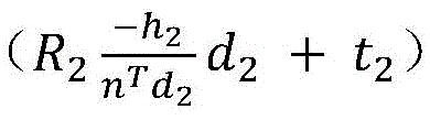 representing a current first coordinate corresponding to the current perception image of the end point of the target dotted line segment in a world coordinate system; { R1,t1Showing the corresponding historical pose of the historical image shot by the camera, and R2,t2Representing the current pose corresponding to the current image shot by the camera; h is1Representing the height of the history to the ground h when the camera takes the history image2Representing the current height to the ground when the camera takes the current image; n represents a ground normal vector oriented upward; d1Representing the observation direction of the endpoint of the target virtual line segment corresponding to the historical pose; d2And representing the observation direction of the endpoint of the target virtual line segment corresponding to the current pose.
Optionally, the apparatus further comprises:
after determining the current ground height of the camera, extracting target virtual line segment end points matched with the current perception image from the history perception image to obtain the current ground height corresponding to each target virtual line segment end point for each history perception image containing the virtual line segment end points; estimating a plurality of current ground heights by a least square method to obtain a first ground height corresponding to the camera;
the estimated ground height determining module is configured to determine the first ground height as the estimated ground height of the camera if the first ground height is within a preset height range;
accordingly, the scale estimation module is specifically configured to: and determining an estimated scale of the visual inertial odometer VIO according to the estimated height to the ground and the reference height to the ground of the camera.
Optionally, the apparatus further comprises:
the second ground height determining module is configured to estimate a plurality of estimated ground heights obtained by traversing all history perception images containing virtual line segment end points through a least square method to obtain a second ground height corresponding to the camera;
a target height-to-ground determination module configured to determine the second height-to-ground as a target height-to-ground of the camera if the second height-to-ground is within a preset height range;
accordingly, the scale estimation module is specifically configured to: and determining an estimated scale of the visual inertial odometer VIO according to the target ground height and the reference height of the camera to the ground.
Optionally, the apparatus further comprises:
the target road point extraction module is configured to determine a road area within a set range in front of the current vehicle when the virtual line segment end point is identified not to exist in the current perception image, and extract a target road point with a gradient value larger than a set threshold value from the road area;
a current ground height estimation module configured to adjust the ground height of the camera according to the equal relationship between the luminance value of the target road point in the current perception image and the luminance value in the historical perception image, so that the value of a luminosity error function taking the ground height of the camera as a parameter reaches a minimum value, and taking the corresponding ground height of the camera when the function value is minimum as the current ground height of the camera;
and the historical perception image is a previous frame perception image adjacent to the current perception image.
Optionally, the photometric value of the target road point in the historical perceptual image is determined by:
determining the current pixel coordinates of the target road point in the current perception image;
according to the current pose corresponding to the current image shot by the camera and the historical pose corresponding to the previous frame image adjacent to the current image shot by the camera, determining a coordinate transformation relation of the target road point in a camera coordinate system corresponding to the current pose and in a camera coordinate system corresponding to the historical pose, wherein the coordinate transformation relation takes the ground height of the camera as a parameter;
and determining historical pixel coordinates of the target road point in the historical perception image according to the coordinate conversion relation and the current pixel coordinates, and determining a corresponding photometric value according to the historical pixel coordinates.
Optionally, the apparatus further comprises:
the iterative optimization module is configured to perform iterative optimization on the current ground height based on a Gauss-Newton method, and within a set iteration number, if a second ground height obtained through iteration is within a preset height range, the obtained second ground height is used as a target ground height of the camera;
correspondingly, the scale estimation module is specifically configured to determine an estimated scale of the visual inertial odometer VIO according to the target height to ground and the reference height to ground of the camera.
In a third aspect, an embodiment of the present invention further provides a vehicle-mounted terminal, including:
a memory storing executable program code;
a processor coupled with the memory;
the processor calls the executable program code stored in the memory to perform part or all of the steps of the method for estimating the visual-inertial odometry scale provided by any of the embodiments of the invention.
In a fourth aspect, embodiments of the present invention further provide a computer-readable storage medium storing a computer program including instructions for performing some or all of the steps of the method for estimating a visual inertial odometry scale provided by any of the embodiments of the present invention.
In a fifth aspect, embodiments of the present invention also provide a computer program product, which when run on a computer causes the computer to perform some or all of the steps of the method for estimating a visual odometry scale provided in any of the embodiments of the present invention.
According to the technical scheme provided by the embodiment of the invention, when the virtual line segment end points exist in the perception images, matched target virtual line segment end points in different perception images can be extracted, and the current scale of the VIO can be estimated by determining the current ground height of the camera according to the fact that the coordinates of the same virtual line segment end points in different perception images in a world coordinate system are the same and the height increment of the camera when the current perception image and the historical perception image are shot. The method has small calculation amount, can still estimate the scale in real time under the condition of not increasing hardware, keeps the advantages of low price and low calculation amount of a monocular VIO system, and solves the problem of VIO scale divergence when GPS signals are interfered or influenced.
The invention comprises the following steps:
1. the matched target virtual line segment end points are extracted from different perception images, the current ground height of the camera can be determined according to the same coordinates of the same virtual line segment end points in the different perception images in a world coordinate system and the height increment of the camera when the current perception image and the historical perception image are shot, so that the current scale of the VIO can be estimated by utilizing the current ground height, the problem of VIO scale divergence when a GPS signal is interfered or influenced is solved, and the method is one of the invention points of the invention.
2. Under the application scene that no virtual line segment end points exist in the road, more gradient road surface points with changes are extracted by fully utilizing identification information such as arrows, zebra crossings and the like on the ground so as to optimize the photometric error function, the estimated VIO precision can be more accurate, and the problem of VIO scale divergence when a GPS signal is interfered or influenced is solved.
Drawings
In order to more clearly illustrate the technical solutions in the embodiments of the present invention, the drawings needed to be used in the embodiments will be briefly described below, and it is obvious that the drawings in the following description are only some embodiments of the present invention, and it is obvious for those skilled in the art that other drawings can be obtained according to these drawings without creative efforts.
FIG. 1 is a schematic flow chart diagram of a method for estimating a visual-inertial odometer scale according to an embodiment of the present invention;
FIG. 2 is a schematic flow chart diagram of a method for estimating a visual-inertial odometer scale according to an embodiment of the present invention;
FIG. 3 is a block diagram of a device for estimating the scale of a visual inertial odometer according to an embodiment of the present invention;
fig. 4 is a schematic structural diagram of a vehicle-mounted terminal according to an embodiment of the present invention.
Detailed Description
The technical solutions in the embodiments of the present invention will be clearly and completely described below with reference to the drawings in the embodiments of the present invention, and it is obvious that the described embodiments are only a part of the embodiments of the present invention, and not all of the embodiments. All other embodiments, which can be derived by a person skilled in the art from the embodiments given herein without making any creative effort, shall fall within the protection scope of the present invention.
It is to be noted that the terms "comprises" and "comprising" and any variations thereof in the embodiments and drawings of the present invention are intended to cover non-exclusive inclusions. For example, a process, method, system, article, or apparatus that comprises a list of steps or elements is not limited to only those steps or elements listed, but may alternatively include other steps or elements not listed, or inherent to such process, method, article, or apparatus.
Example one
Referring to fig. 1, fig. 1 is a schematic flow chart of a method for estimating a visual inertial odometer metric according to an embodiment of the present invention. The method is typically applied to a scene in which the GPS signal is interfered or influenced in the automatic driving process, such as a long tunnel scene. The method can be executed by an estimation device of the scale of the visual inertial odometer, the device can be realized by software and/or hardware, and the device can be generally integrated in vehicle-mounted terminals such as a vehicle-mounted Computer, a vehicle-mounted Industrial control Computer (IPC), and the like, and the embodiment of the invention is not limited. As shown in fig. 1, the method provided in this embodiment specifically includes:
110. and when the virtual line segment end points exist in the current perception image, extracting the virtual line segment end points, and matching the virtual line segment end points with the historical perception image containing the virtual line segment end points to obtain matched target virtual line segment end points.
The perception image is obtained by recognizing an image which is acquired by a camera and contains road information by using a preset perception model. The preset perception model can be used for training the perception model by adopting a large number of road sample images marked with image semantic features in advance. The image semantic features may include traffic signs, light poles, lane lines, lane line dotted line endpoints, and the like. The road image containing the road information is input into the trained preset perception model, and the image semantic features in the road image can be obtained based on the recognition result of the preset perception model. The preset perception model can be obtained through the following modes:
constructing a training sample set, wherein the training sample set comprises a plurality of groups of training sample data, and each group of training sample data comprises a road sample image and a corresponding road perception sample image marked with image semantic features; training the built initial neural network based on the training sample set to obtain a preset perception model, wherein the preset perception model enables the road sample images in each set of training sample data to be associated with the corresponding road perception sample images marked with image semantic features. The output of the model is called a perception image. For each frame of perceptual image, it may be saved into a historical frame under the MSCKF (Multi-State Constraint Kalman Filter) framework. When the next frame image is generated, the saved perception images can be used as historical perception images.
In this embodiment, when a virtual line segment endpoint is identified in the current perceptual image, the virtual line segment endpoint may be extracted, and the virtual line segment endpoint may be matched with the virtual line segment endpoint in the historical perceptual image. The historical perception image is any one frame of perception image before the current image is acquired. There are various methods for matching the end points of the dotted line segment in the current perceptual image and the historical perceptual image, for example, for any one end point of the dotted line segment extracted from the current perceptual image, the end point of the dotted line segment in the historical perceptual image, the distance between which and the end point of the dotted line segment is smaller than a preset threshold value, can be used as a matched target end point of the dotted line segment.
120. And determining a current first coordinate and a historical first coordinate of the end point of the target dotted line segment, which respectively correspond to the current perception image and the historical perception image, in a world coordinate system.
For example, a current second coordinate corresponding to the current pose and a historical second coordinate corresponding to the historical pose of the target virtual line segment endpoint under the camera coordinate system can be determined according to the current pose corresponding to the current image shot by the camera and the historical pose corresponding to the historical image shot by the camera; and converting the current second coordinate and the historical second coordinate into a world coordinate system to obtain a corresponding current first coordinate and a corresponding historical first coordinate.
Specifically, when a certain target virtual line segment endpoint is tracked, d represents the observation direction of the target virtual line segment endpoint; the ground equation is: n isTX + h is 0, and ρ represents the depth of the end point of the target virtual line segment; n represents a ground normal vector oriented upward; h represents the camera height to ground, from which the ground constraint equation and the camera observation equation can be based as follows:

obtaining the coordinate X of the target virtual line segment endpoint under a camera coordinate system: in this embodiment, the current second coordinate corresponding to the current pose of the camera is the current second coordinate of the target virtual line segment endpoint in the camera coordinate system
 And the historical second coordinate corresponding to the historical pose of the camera is
 wherein ,d1Representing the observation direction of the endpoint of the target virtual line segment corresponding to the historical pose; d2And representing the observation direction of the endpoint of the target virtual line segment corresponding to the current pose.
Let the history pose corresponding to the history image shot by the camera be { R1,t1}; the current pose corresponding to the current image shot by the camera is { R2,t2According to the second coordinate, the current second coordinate of the target virtual line segment end point in the camera coordinate system corresponding to the current pose of the camera can be obtained And converting the current first coordinate into a world coordinate system to obtain the current first coordinate:
 historical second coordinates of the end points of the target virtual line segment corresponding to the historical pose of the camera in the camera coordinate system can also be used
 And converting into a world coordinate system to obtain historical first coordinates:
 wherein ,h1Representing the height of the history to the ground h when the camera takes the history image2Which represents the current height to ground when the camera takes the current image, i.e. the height to ground of the camera to be determined in this embodiment.
130. And determining the current ground height of the camera according to the equal relation between the current first coordinate and the historical first coordinate and the height increment of the camera when the current perception image and the historical perception image are shot.
Since the coordinates of the same dotted line segment endpoint in different images in the world coordinate system are equal, the equality relationship between the historical first coordinate and the current first coordinate can be established. The height increment of the camera when the current perception image and the historical perception image are captured can be represented by the rotation angle R, the displacement t and the ground normal vector n of the camera. Specifically, the following constraint equation may be established:

through the constraint equation, the current ground height h of the camera can be obtained2。
140. And determining an estimated scale of the visual inertial odometer VIO according to the current height to the ground and the reference height of the camera to the ground.
The height prior truth value can be used as the reference height of the camera to the ground, and the reference height to the ground and the current height to the ground obtained in the above steps are subjected to quotient so as to obtain the estimation scale of the VIO.
Further, for each history perception image containing the virtual line segment end points, extracting target virtual line segment end points matched with the virtual line segment end points in the current perception image from the history perception image, and performing the steps to obtain a plurality of current ground heights corresponding to the target virtual line segment end points. Estimating the current heights of the ground by adopting a least square method to obtain a first height of the ground corresponding to the camera; if the first ground height is within the preset height range, determining the first ground height as the estimated ground height of the camera; correspondingly, an estimation scale of the visual inertia odometer VIO is determined according to the estimated height to the ground and the reference height of the camera to the ground. This arrangement improves the accuracy of the VIO estimation metric.
Furthermore, traversing all the stored historical perception images containing the virtual line segment end points, and estimating the estimated height to the ground corresponding to all the historical perception images by adopting a least square method again to obtain a second height to the ground corresponding to the camera. And if the second ground height is within the preset height range, determining the second ground height as the target ground height of the camera. Correspondingly, an estimated scale of the visual inertial odometer VIO is determined according to the target height to the ground and the reference height of the camera to the ground. By the arrangement, the accuracy of the VIO estimation scale can be further improved.
According to the technical scheme provided by the embodiment, when the virtual line segment end points exist in the perception images, matched target virtual line segment end points in different perception images can be extracted, and the current scale of the VIO can be estimated by determining the current ground height of the camera according to the characteristic that the coordinates of the same virtual line segment end point in different perception images in a world coordinate system are the same and the height increment of the camera when the current perception image and the historical perception image are shot. The method has small calculation amount, can still estimate the scale in real time under the condition of not increasing hardware, keeps the advantages of low price and low calculation amount of a monocular VIO system, and solves the problem of VIO scale divergence when GPS signals are interfered or influenced.
Example two
Referring to fig. 2, fig. 2 is a schematic flow chart of a method for estimating a visual inertial odometer metric according to an embodiment of the present invention. The embodiment is optimized on the basis of the embodiment, and is mainly applied to a road surface scene without a virtual line segment end point on a road surface. As shown in fig. 2, the method includes:
210. when recognizing that no virtual line segment endpoint exists in the current perception image, determining a road surface area in a set range in front of the current vehicle, and extracting a target road surface point with a gradient value larger than a set threshold value from the road surface area.
For example, when extracting the target road surface point, the road surface area may be divided into grids, and the feature points with gradient values greater than a set threshold value are extracted from each grid, so as to ensure that enough road surface feature points with uniform distribution and gradient change can be extracted from the whole road surface area. Specifically, in an actual application scenario, the feature points may be road lines, arrows, zebra crossings, shadows and tree shadows of buildings, stains on a road surface, and the like.
220. And according to the equal relation between the photometric value of the target road point in the current perception image and the photometric value in the historical perception image, adjusting the ground height of the camera to minimize the value of a photometric error function taking the ground height of the camera as a parameter, and taking the corresponding ground height of the camera when the function value is minimized as the current ground height of the camera.
It will be appreciated that the luminance values in different pictures are the same for the same pixel. Therefore, the target road point has an equality relationship between the photometric value of the current perceived image and the photometric value in the historical perceived image. The historical perceptual image referred to in this embodiment is a previous frame perceptual image adjacent to the current perceptual image.
Illustratively, the photometric value of the target road point in the perception image may be determined by the pixel coordinates of the target road point in the image. For the current perceptual image, the pixel coordinates of the target road point therein may be extracted. For the historical perception image, determining a coordinate transformation relation between the target road point in a camera coordinate system corresponding to the current pose and a camera coordinate system corresponding to the historical pose according to the current pose corresponding to the current image shot by the camera and the historical pose corresponding to the previous frame image adjacent to the current image shot by the camera; according to the coordinate conversion relation and the current pixel coordinate, historical pixel coordinates of the target road point in the historical perception image can be determined, and therefore the corresponding photometric value can be determined according to the historical pixel coordinates.
Specifically, let the coordinate of the target road point in the camera coordinate system corresponding to the current pose of the camera be P, and the coordinate in the historical coordinate system corresponding to the historical pose of the camera be (RP + t), where { R, t } is the relative rotation and displacement of the camera provided by the MSCKF front end between two adjacent frames of images. Let d be the direction vector of the target road point in the camera coordinate system when the camera takes the previous frame image1The direction vector in the camera coordinate system when the camera takes the current image is d2Then, according to the relative rotation and displacement between two adjacent frames of images shot by the camera, the coordinate transformation relationship of the target road point in the camera coordinate system corresponding to the current pose and the camera coordinate system corresponding to the historical pose is obtained as follows: through the coordinate conversion relation and the current pixel coordinate x of the target road point in the current perception image, the method can be used for realizing the target road pointObtaining the historical pixel coordinates W (x, n, h) of the target road surface point in the historical perception image, and accordingly obtaining a luminosity error function with the height of the ground of the camera as a parameter:

by adjusting the ground height h and the ground normal vector n of the camera, the value of the luminosity error function can be minimized, and at this time, the corresponding ground height of the camera with the minimum function value can be used as the current ground height of the camera to be determined in this embodiment.
Furthermore, after the current ground height of the camera is obtained, iterative optimization can be performed on the current ground height based on a Gauss-Newton method, and within the set iteration times, if the second ground height obtained through iteration is within the preset height range, the obtained second ground height is used as the target ground height of the camera, so that the accuracy of the ground height of the camera is improved. Accordingly, an estimated scale of the visual inertial odometer VIO may be determined based on the target height to ground and the reference height of the camera to ground.
230. And determining an estimated scale of the visual inertial odometer VIO according to the current height to the ground and the reference height of the camera to the ground.
On the basis of the above embodiment, in an application scene where no virtual line segment end point exists in a road, the embodiment makes full use of identification information such as an arrow and a zebra crossing on the ground, and can greatly improve the scene coverage. By extracting more pavement points with changing gradients to optimize the luminosity error function, the estimated VIO precision can be more accurate, and the problem of VIO scale divergence when GPS signals are interfered or influenced is solved.
EXAMPLE III
Referring to fig. 3, fig. 3 is a block diagram of a device for estimating a visual inertial odometer metric according to an embodiment of the present invention. As shown in fig. 3, the apparatus specifically includes: a target virtual line segment endpoint determination module 310, a coordinate determination module 320, a current ground height determination module 330, and a scale estimation module 340; wherein,
a target virtual line segment endpoint determining module 310, configured to, when a virtual line segment endpoint is identified in the current sensing image, extract the virtual line segment endpoint, and match the virtual line segment endpoint with a historical sensing image containing the virtual line segment endpoint to obtain a matched target virtual line segment endpoint;
a coordinate determination module 320 configured to determine a current first coordinate and a historical first coordinate of the target dotted line segment endpoint, which correspond to the current perceptual image and the historical perceptual image, respectively, in a world coordinate system;
a current ground height determining module 330 configured to determine a current ground height of the camera according to an equality relationship between the current first coordinate and the historical first coordinate, and a height increment of the camera when the current sensing image and the historical sensing image are captured;
and the scale estimation module 340 is configured to determine an estimated scale of the visual inertial odometer VIO according to the current height to the ground and the reference height to the ground of the camera.
Optionally, the coordinate determination module is specifically configured to:
determining a current second coordinate of the endpoint of the target virtual line segment corresponding to the current pose and a historical second coordinate corresponding to the historical pose under a camera coordinate system according to the current pose corresponding to the current image shot by the camera and the historical pose corresponding to the historical image shot by the camera;
and converting the current second coordinate and the historical second coordinate into a world coordinate system to obtain a corresponding current first coordinate and a corresponding historical first coordinate.
Optionally, the current height-to-ground determining module is specifically configured to:
determining the current height to ground of the camera according to the following formula:

wherein , historical first coordinates which represent the end points of the target dotted line segments and correspond to the historical perception images in a world coordinate system;
 representing a current first coordinate corresponding to the current perception image of the end point of the target dotted line segment in a world coordinate system; { R1,t1Showing the corresponding historical pose of the historical image shot by the camera, and R2,t2Representing the current pose corresponding to the current image shot by the camera; h is1Representing the height of the history to the ground h when the camera takes the history image2Representing the current height to the ground when the camera takes the current image; n represents a ground normal vector oriented upward; d1Representing the observation direction of the endpoint of the target virtual line segment corresponding to the historical pose; d2And representing the observation direction of the endpoint of the target virtual line segment corresponding to the current pose.
Optionally, the apparatus further comprises:
after determining the current ground height of the camera, extracting target virtual line segment end points matched with the current perception image from the history perception image to obtain the current ground height corresponding to each target virtual line segment end point for each history perception image containing the virtual line segment end points; estimating a plurality of current ground heights by a least square method to obtain a first ground height corresponding to the camera;
the estimated ground height determining module is configured to determine the first ground height as the estimated ground height of the camera if the first ground height is within a preset height range;
accordingly, the scale estimation module is specifically configured to: and determining an estimated scale of the visual inertial odometer VIO according to the estimated height to the ground and the reference height to the ground of the camera.
Optionally, the apparatus further comprises:
the second ground height determining module is configured to estimate a plurality of estimated ground heights obtained by traversing all history perception images containing virtual line segment end points through a least square method to obtain a second ground height corresponding to the camera;
a target height-to-ground determination module configured to determine the second height-to-ground as a target height-to-ground of the camera if the second height-to-ground is within a preset height range;
accordingly, the scale estimation module is specifically configured to: and determining an estimated scale of the visual inertial odometer VIO according to the target ground height and the reference height of the camera to the ground.
Optionally, the apparatus further comprises:
the target road point extraction module is configured to determine a road area within a set range in front of the current vehicle when the virtual line segment end point is identified not to exist in the current perception image, and extract a target road point with a gradient value larger than a set threshold value from the road area;
a current ground height estimation module configured to adjust the ground height of the camera according to the equal relationship between the luminance value of the target road point in the current perception image and the luminance value in the historical perception image, so that the value of a luminosity error function taking the ground height of the camera as a parameter reaches a minimum value, and taking the corresponding ground height of the camera when the function value is minimum as the current ground height of the camera;
and the historical perception image is a previous frame perception image adjacent to the current perception image.
Optionally, the photometric value of the target road point in the historical perceptual image is determined by:
determining the current pixel coordinates of the target road point in the current perception image;
according to the current pose corresponding to the current image shot by the camera and the historical pose corresponding to the previous frame image adjacent to the current image shot by the camera, determining a coordinate transformation relation of the target road point in a camera coordinate system corresponding to the current pose and in a camera coordinate system corresponding to the historical pose, wherein the coordinate transformation relation takes the ground height of the camera as a parameter;
and determining historical pixel coordinates of the target road point in the historical perception image according to the coordinate conversion relation and the current pixel coordinates, and determining a corresponding photometric value according to the historical pixel coordinates.
Optionally, the apparatus further comprises:
the iterative optimization module is configured to perform iterative optimization on the current ground height based on a Gauss-Newton method, and within a set iteration number, if a second ground height obtained through iteration is within a preset height range, the obtained second ground height is used as a target ground height of the camera;
correspondingly, the scale estimation module is specifically configured to determine an estimated scale of the visual inertial odometer VIO according to the target height to ground and the reference height to ground of the camera.
The estimation device of the visual inertia odometer scale provided by the embodiment of the invention can execute the estimation method of the visual inertia odometer scale provided by any embodiment of the invention, and has corresponding functional modules and beneficial effects of the execution method. Technical details that are not elaborated in the above embodiments may be referred to the estimation method of the visual inertial odometer scale provided by any of the embodiments of the invention.
Example four
Referring to fig. 4, fig. 4 is a schematic structural diagram of a vehicle-mounted terminal according to an embodiment of the present invention. As shown in fig. 4, the in-vehicle terminal may include:
a memory 701 in which executable program code is stored;
a processor 702 coupled to the memory 701;
wherein the processor 702 invokes executable program code stored in the memory 701 to perform the method for estimating the visual-inertial odometry metric provided by any of the embodiments of the invention.
The embodiment of the invention discloses a computer-readable storage medium which stores a computer program, wherein the computer program enables a computer to execute the estimation method of the visual inertia odometer scale provided by any embodiment of the invention.
The embodiment of the invention discloses a computer program product, wherein when the computer program product runs on a computer, the computer is caused to execute part or all of the steps of the estimation method of the visual inertia odometry scale provided by any embodiment of the invention.
In various embodiments of the present invention, it should be understood that the sequence numbers of the above-mentioned processes do not imply an inevitable order of execution, and the execution order of the processes should be determined by their functions and inherent logic, and should not constitute any limitation on the implementation process of the embodiments of the present invention.
In the embodiments provided herein, it should be understood that "B corresponding to A" means that B is associated with A from which B can be determined. It should also be understood, however, that determining B from a does not mean determining B from a alone, but may also be determined from a and/or other information.
In addition, functional units in the embodiments of the present invention may be integrated into one processing unit, or each unit may exist alone physically, or two or more units are integrated into one unit. The integrated unit can be realized in a form of hardware, and can also be realized in a form of a software functional unit.
The integrated units, if implemented as software functional units and sold or used as a stand-alone product, may be stored in a computer accessible memory. Based on such understanding, the technical solution of the present invention, which is a part of or contributes to the prior art in essence, or all or part of the technical solution, can be embodied in the form of a software product, which is stored in a memory and includes several requests for causing a computer device (which may be a personal computer, a server, a network device, or the like, and may specifically be a processor in the computer device) to execute part or all of the steps of the above-described method of each embodiment of the present invention.
It will be understood by those skilled in the art that all or part of the steps in the methods of the embodiments described above may be implemented by hardware instructions of a program, and the program may be stored in a computer-readable storage medium, where the storage medium includes Read-Only Memory (ROM), Random Access Memory (RAM), Programmable Read-Only Memory (PROM), Erasable Programmable Read-Only Memory (EPROM), One-time Programmable Read-Only Memory (OTPROM), Electrically Erasable Programmable Read-Only Memory (EEPROM), Compact Disc Read-Only Memory (CD-ROM), or other Memory, such as a magnetic disk, or a combination thereof, A tape memory, or any other medium readable by a computer that can be used to carry or store data.
The method and the device for estimating the scale of the visual-inertial odometer disclosed by the embodiment of the invention are described in detail, the principle and the implementation mode of the invention are explained by applying a specific example, and the description of the embodiment is only used for helping to understand the method and the core idea of the invention; meanwhile, for a person skilled in the art, according to the idea of the present invention, there may be variations in the specific embodiments and the application scope, and in summary, the content of the present specification should not be construed as a limitation to the present invention.
Claims (10)
1. A method for estimating a visual inertial odometer scale is applied to automatic driving and is characterized by comprising the following steps:
when the virtual line segment end points exist in the current perception image, extracting the virtual line segment end points, and matching the virtual line segment end points with the historical perception image containing the virtual line segment end points to obtain matched target virtual line segment end points;
determining a current first coordinate and a historical first coordinate which correspond to a current perception image and a historical perception image respectively at the end point of the target dotted line segment in a world coordinate system;
determining the current ground height of the camera according to the equal relation between the current first coordinate and the historical first coordinate and the height increment of the camera when the current sensing image and the historical sensing image are shot;
and determining an estimated scale of the visual inertial odometer VIO according to the current height to the ground and the reference height to the ground of the camera.
2. The method of claim 1, wherein determining the current first coordinate and the historical first coordinate of the target dotted line segment endpoint corresponding to the current sensing image and the historical sensing image respectively in a world coordinate system comprises:
determining a current second coordinate of the endpoint of the target virtual line segment corresponding to the current pose and a historical second coordinate corresponding to the historical pose under a camera coordinate system according to the current pose corresponding to the current image shot by the camera and the historical pose corresponding to the historical image shot by the camera;
and converting the current second coordinate and the historical second coordinate into a world coordinate system to obtain a corresponding current first coordinate and a corresponding historical first coordinate.
3. The method of claim 1, wherein determining the current ground height of the camera according to the equality between the current first coordinate and the historical first coordinate and the height increment of the camera when capturing the current perception image and the historical perception image comprises:
determining the current height to ground of the camera according to the following formula:

wherein , historical first coordinates which represent the end points of the target dotted line segments and correspond to the historical perception images in a world coordinate system;
 representing a current first coordinate corresponding to the current perception image of the end point of the target dotted line segment in a world coordinate system; { R1,t1Showing the corresponding historical pose of the historical image shot by the camera, and R2,t2Representing the current pose corresponding to the current image shot by the camera; h is1Representing the height of the history to the ground h when the camera takes the history image2Representing the current height to the ground when the camera takes the current image; n represents a ground normal vector oriented upward; d1Representing the observation direction of the endpoint of the target virtual line segment corresponding to the historical pose; d2And representing the observation direction of the endpoint of the target virtual line segment corresponding to the current pose.
4. The method of claim 1, wherein after determining the current height to ground of the camera, the method further comprises:
for each historical sensing image containing the virtual line segment end points, extracting target virtual line segment end points matched with the current sensing image from the historical sensing image to obtain the current ground height corresponding to each target virtual line segment end point;
estimating a plurality of current ground heights by a least square method to obtain a first ground height corresponding to the camera;
if the first ground height is within the preset height range, determining the first ground height as the estimated ground height of the camera;
correspondingly, an estimation scale of the visual inertia odometer VIO is determined according to the estimated height to the ground and the reference height to the ground of the camera.
5. The method of claim 4, further comprising:
estimating a plurality of estimated ground heights obtained by traversing all history perception images containing virtual line segment end points through a least square method to obtain a second ground height corresponding to the camera;
if the second ground height is within the preset height range, determining the second ground height as the target ground height of the camera;
correspondingly, an estimated scale of the visual inertial odometer VIO is determined according to the target ground height and the reference height of the camera to the ground.
6. The method of claim 1, further comprising:
when recognizing that no virtual line segment endpoint exists in the current perception image, determining a road surface area in a set range in front of the current vehicle, and extracting a target road surface point with a gradient value larger than a set threshold value from the road surface area;
according to the equal relation between the luminance value of the target road point in the current perception image and the luminance value in the historical perception image, the ground height of the camera is adjusted, so that the value of a luminance error function taking the ground height of the camera as a parameter is minimum, and the corresponding ground height of the camera when the function value is minimum is taken as the current ground height of the camera;
and the historical perception image is a previous frame perception image adjacent to the current perception image.
7. The method of claim 6, wherein the photometric value of the target road point in the historical perceptual image is determined by:
determining the current pixel coordinates of the target road point in the current perception image;
according to the current pose corresponding to the current image shot by the camera and the historical pose corresponding to the previous frame image adjacent to the current image shot by the camera, determining a coordinate transformation relation of the target road point in a camera coordinate system corresponding to the current pose and in a camera coordinate system corresponding to the historical pose, wherein the coordinate transformation relation takes the ground height of the camera as a parameter;
and determining historical pixel coordinates of the target road point in the historical perception image according to the coordinate conversion relation and the current pixel coordinates, and determining a corresponding photometric value according to the historical pixel coordinates.
8. The method of claim 7, further comprising:
performing iterative optimization on the current ground height based on a Gauss-Newton method, and within a set iteration number, if a second ground height obtained by iteration is within a preset height range, taking the obtained second ground height as a target ground height of the camera;
correspondingly, an estimated scale of the visual inertial odometer VIO is determined according to the target ground height and the reference height of the camera to the ground.
9. An estimation device of a visual inertia odometer scale, which is applied to automatic driving, and is characterized by comprising:
the target virtual line segment endpoint determining module is configured to extract a virtual line segment endpoint when the virtual line segment endpoint is identified to exist in the current perception image, and match the virtual line segment endpoint with a historical perception image containing the virtual line segment endpoint to obtain a matched target virtual line segment endpoint;
the coordinate determination module is configured to determine a current first coordinate and a historical first coordinate, corresponding to the current perception image and the historical perception image respectively, of the target dotted line segment endpoint in a world coordinate system;
a current ground height determining module configured to determine a current ground height of the camera according to an equality relationship between the current first coordinate and the historical first coordinate and a height increment of the camera when the current perception image and the historical perception image are shot;
and the scale estimation module is configured to determine an estimated scale of the visual inertial odometer VIO according to the current height to the ground and the reference height to the ground of the camera.
10. The apparatus of claim 9, further comprising:
the target road point extraction module is configured to determine a road area within a set range in front of the current vehicle when the virtual line segment end point is identified not to exist in the current perception image, and extract a target road point with a gradient value larger than a set threshold value from the road area;
a current ground height estimation module configured to adjust the ground height of the camera according to the equal relationship between the luminance value of the target road point in the current perception image and the luminance value in the historical perception image, so that the value of a luminosity error function taking the ground height of the camera as a parameter reaches a minimum value, and taking the corresponding ground height of the camera when the function value is minimum as the current ground height of the camera;
and the historical perception image is a previous frame perception image adjacent to the current perception image.
Priority Applications (1)
| Application Number | Priority Date | Filing Date | Title |
|---|---|---|---|
| CN202010069343.9A CN113223064B (en) | 2020-01-21 | 2020-01-21 | Visual inertial odometer scale estimation method and device |
Applications Claiming Priority (1)
| Application Number | Priority Date | Filing Date | Title |
|---|---|---|---|
| CN202010069343.9A CN113223064B (en) | 2020-01-21 | 2020-01-21 | Visual inertial odometer scale estimation method and device |
Publications (2)
| Publication Number | Publication Date |
|---|---|
| CN113223064A true CN113223064A (en) | 2021-08-06 |
| CN113223064B CN113223064B (en) | 2023-09-15 |
Family
ID=77085117
Family Applications (1)
| Application Number | Title | Priority Date | Filing Date |
|---|---|---|---|
| CN202010069343.9A Active CN113223064B (en) | 2020-01-21 | 2020-01-21 | Visual inertial odometer scale estimation method and device |
Country Status (1)
| Country | Link |
|---|---|
| CN (1) | CN113223064B (en) |
Cited By (3)
| Publication number | Priority date | Publication date | Assignee | Title |
|---|---|---|---|---|
| CN114485649A (en) * | 2022-02-09 | 2022-05-13 | 北京自动化控制设备研究所 | Unmanned aerial vehicle-oriented inertial, visual and height information fusion navigation method |
| CN114529566A (en) * | 2021-12-30 | 2022-05-24 | 北京城市网邻信息技术有限公司 | Image processing method, device, equipment and storage medium |
| CN114494849B (en) * | 2021-12-21 | 2024-04-09 | 重庆特斯联智慧科技股份有限公司 | Road surface state identification method and system for wheeled robot |
Family Cites Families (7)
| Publication number | Priority date | Publication date | Assignee | Title |
|---|---|---|---|---|
| JP5849942B2 (en) * | 2012-12-25 | 2016-02-03 | 株式会社日本自動車部品総合研究所 | In-vehicle image processing device |
| CN104318561B (en) * | 2014-10-22 | 2017-05-03 | 上海理工大学 | Method for detecting vehicle motion information based on integration of binocular stereoscopic vision and optical flow |
| CN105606127A (en) * | 2016-01-11 | 2016-05-25 | 北京邮电大学 | Calibration method for relative attitude of binocular stereo camera and inertial measurement unit |
| CN106556412A (en) * | 2016-11-01 | 2017-04-05 | 哈尔滨工程大学 | The RGB D visual odometry methods of surface constraints are considered under a kind of indoor environment |
| CN108489482B (en) * | 2018-02-13 | 2019-02-26 | 视辰信息科技(上海)有限公司 | The realization method and system of vision inertia odometer |
| CN109506642B (en) * | 2018-10-09 | 2021-05-28 | 浙江大学 | A robot multi-camera visual inertial real-time positioning method and device |
| CN110375738B (en) * | 2019-06-21 | 2023-03-14 | 西安电子科技大学 | Monocular synchronous positioning and mapping attitude calculation method fused with inertial measurement unit |
-
2020
- 2020-01-21 CN CN202010069343.9A patent/CN113223064B/en active Active
Cited By (4)
| Publication number | Priority date | Publication date | Assignee | Title |
|---|---|---|---|---|
| CN114494849B (en) * | 2021-12-21 | 2024-04-09 | 重庆特斯联智慧科技股份有限公司 | Road surface state identification method and system for wheeled robot |
| CN114529566A (en) * | 2021-12-30 | 2022-05-24 | 北京城市网邻信息技术有限公司 | Image processing method, device, equipment and storage medium |
| CN114485649A (en) * | 2022-02-09 | 2022-05-13 | 北京自动化控制设备研究所 | Unmanned aerial vehicle-oriented inertial, visual and height information fusion navigation method |
| CN114485649B (en) * | 2022-02-09 | 2023-09-12 | 北京自动化控制设备研究所 | Unmanned aerial vehicle-oriented inertial, visual and altitude information fusion navigation method |
Also Published As
| Publication number | Publication date |
|---|---|
| CN113223064B (en) | 2023-09-15 |
Similar Documents
| Publication | Publication Date | Title |
|---|---|---|
| CN109061703B (en) | Method, apparatus, device and computer-readable storage medium for positioning | |
| CN108961327B (en) | Monocular depth estimation method and device, equipment and storage medium thereof | |
| CN108318043B (en) | Method, apparatus, and computer-readable storage medium for updating electronic map | |
| CN107167826B (en) | Vehicle longitudinal positioning system and method based on variable grid image feature detection in automatic driving | |
| CN111830953A (en) | Vehicle self-positioning method, device and system | |
| CN111261016B (en) | Road map construction method and device and electronic equipment | |
| CN105628951A (en) | Method and device for measuring object speed | |
| Chen et al. | Vision-based positioning for internet-of-vehicles | |
| KR20190030474A (en) | Method and apparatus of calculating depth map based on reliability | |
| CN112347205A (en) | Method and device for updating error state of vehicle | |
| CN112700486B (en) | Method and device for estimating depth of road surface lane line in image | |
| CN113223064B (en) | Visual inertial odometer scale estimation method and device | |
| Rasib et al. | Pixel level segmentation based drivable road region detection and steering angle estimation method for autonomous driving on unstructured roads | |
| CN117132649A (en) | Ship video positioning method and device for artificial intelligent Beidou satellite navigation fusion | |
| CN113887391A (en) | Method and device for recognizing road sign and automatic driving vehicle | |
| CN113763466B (en) | Loop detection method and device, electronic equipment and storage medium | |
| CN114248778A (en) | Positioning method and positioning device of mobile equipment | |
| CN112507857B (en) | Lane line updating method, device, equipment and storage medium | |
| CN111783611B (en) | Unmanned vehicle positioning method and device, unmanned vehicle and storage medium | |
| CN113450457A (en) | Road reconstruction method, apparatus, computer device and storage medium | |
| CN113902047B (en) | Image element matching method, device, equipment and storage medium | |
| CN114111817B (en) | Vehicle positioning method and system based on SLAM map and high-precision map matching | |
| CN116358528A (en) | Map updating method, map updating device, self-mobile device and storage medium | |
| CN116762094A (en) | Data processing method and device | |
| CN112818866A (en) | Vehicle positioning method and device and electronic equipment |
Legal Events
| Date | Code | Title | Description |
|---|---|---|---|
| PB01 | Publication | ||
| PB01 | Publication | ||
| SE01 | Entry into force of request for substantive examination | ||
| SE01 | Entry into force of request for substantive examination | ||
| TA01 | Transfer of patent application right | ||
| TA01 | Transfer of patent application right |
Effective date of registration: 20220303 Address after: 100083 unit 501, block AB, Dongsheng building, No. 8, Zhongguancun East Road, Haidian District, Beijing Applicant after: BEIJING MOMENTA TECHNOLOGY Co.,Ltd. Address before: 100083 room 28, 4 / F, block a, Dongsheng building, 8 Zhongguancun East Road, Haidian District, Beijing Applicant before: BEIJING CHUSUDU TECHNOLOGY Co.,Ltd. |
|
| GR01 | Patent grant | ||
| GR01 | Patent grant |