CN113216279B - Horizontal hollow pipe landfill vibration isolation barrier and construction process thereof - Google Patents
Horizontal hollow pipe landfill vibration isolation barrier and construction process thereof Download PDFInfo
- Publication number
- CN113216279B CN113216279B CN202110575496.5A CN202110575496A CN113216279B CN 113216279 B CN113216279 B CN 113216279B CN 202110575496 A CN202110575496 A CN 202110575496A CN 113216279 B CN113216279 B CN 113216279B
- Authority
- CN
- China
- Prior art keywords
- vibration isolation
- pipe
- concrete hollow
- isolation barrier
- hollow pipe
- Prior art date
- Legal status (The legal status is an assumption and is not a legal conclusion. Google has not performed a legal analysis and makes no representation as to the accuracy of the status listed.)
- Active
Links
- 238000002955 isolation Methods 0.000 title claims abstract description 88
- 230000004888 barrier function Effects 0.000 title claims abstract description 53
- 238000010276 construction Methods 0.000 title claims abstract description 34
- 238000000034 method Methods 0.000 title claims abstract description 11
- 230000008569 process Effects 0.000 title claims abstract description 7
- 229910000831 Steel Inorganic materials 0.000 claims abstract description 22
- 230000000694 effects Effects 0.000 claims abstract description 22
- 239000010959 steel Substances 0.000 claims abstract description 22
- 239000002689 soil Substances 0.000 claims abstract description 18
- 239000004927 clay Substances 0.000 claims abstract description 11
- 238000009412 basement excavation Methods 0.000 claims abstract description 6
- 230000007613 environmental effect Effects 0.000 claims abstract description 3
- 238000009933 burial Methods 0.000 claims description 5
- 239000011083 cement mortar Substances 0.000 claims description 3
- 239000004570 mortar (masonry) Substances 0.000 claims description 3
- 230000003044 adaptive effect Effects 0.000 abstract 1
- 230000005540 biological transmission Effects 0.000 description 11
- 238000010586 diagram Methods 0.000 description 10
- 230000009286 beneficial effect Effects 0.000 description 2
- 238000005516 engineering process Methods 0.000 description 2
- 239000000463 material Substances 0.000 description 2
- 230000007547 defect Effects 0.000 description 1
- 239000000945 filler Substances 0.000 description 1
- 239000006260 foam Substances 0.000 description 1
- 230000003993 interaction Effects 0.000 description 1
- 230000001902 propagating effect Effects 0.000 description 1
- 230000009467 reduction Effects 0.000 description 1
- XLYOFNOQVPJJNP-UHFFFAOYSA-N water Substances O XLYOFNOQVPJJNP-UHFFFAOYSA-N 0.000 description 1
Images


Classifications
-
- E—FIXED CONSTRUCTIONS
- E02—HYDRAULIC ENGINEERING; FOUNDATIONS; SOIL SHIFTING
- E02D—FOUNDATIONS; EXCAVATIONS; EMBANKMENTS; UNDERGROUND OR UNDERWATER STRUCTURES
- E02D31/00—Protective arrangements for foundations or foundation structures; Ground foundation measures for protecting the soil or the subsoil water, e.g. preventing or counteracting oil pollution
- E02D31/08—Protective arrangements for foundations or foundation structures; Ground foundation measures for protecting the soil or the subsoil water, e.g. preventing or counteracting oil pollution against transmission of vibrations or movements in the foundation soil
Landscapes
- Engineering & Computer Science (AREA)
- Life Sciences & Earth Sciences (AREA)
- Environmental & Geological Engineering (AREA)
- Hydrology & Water Resources (AREA)
- General Life Sciences & Earth Sciences (AREA)
- Mining & Mineral Resources (AREA)
- Paleontology (AREA)
- Civil Engineering (AREA)
- General Engineering & Computer Science (AREA)
- Structural Engineering (AREA)
- Bulkheads Adapted To Foundation Construction (AREA)
Abstract
Description
技术领域technical field
本发明涉及一种水平空心管填埋隔振屏障及其施工工艺,属隔振屏障技术领域。The invention relates to a vibration-isolation barrier for horizontal hollow tube filling and a construction process thereof, which belongs to the technical field of vibration-isolation barriers.
背景技术Background technique
近年来,随着我国列车速度的飞速提升,列车通行引起的地面振动对临近的建筑物及地下管线、精密仪器和设备、人们的生活环境和工作环境产生了不可忽略的危害。空沟、填充沟、排桩和波阻板是目前最常采用的隔振措施,已在土木工程领域得到了广泛使用。然而,当前这些常见的隔振措施仍然存在着一些亟待解决的问题。In recent years, with the rapid increase of train speed in my country, the ground vibration caused by train traffic has caused non-negligible harm to adjacent buildings, underground pipelines, precision instruments and equipment, and people's living and working environments. Empty trenches, filled trenches, row piles and wave barriers are the most commonly used vibration isolation measures at present, and have been widely used in the field of civil engineering. However, there are still some problems to be solved urgently in these common vibration isolation measures.
问题包括:(1)深度是影响隔振屏障隔振效果的最重要因素之一,空沟由于其沟壁缺乏支撑,导致沟壁的稳定性较差,修建大深度的沟屏障可能由于沟壁失稳而造成坍塌,而深度较小的空沟只在一定范围内能够取得较满意的隔振效果,深度受限这一缺陷大大制约了空沟的适用范围;(2)通过在空沟内部填充水、混凝土、土工泡沫等材料而形成的填充沟,虽在稳定性上较空沟有较大提升,但在沟槽尺寸相同的情况下,填充沟的隔振效果较空沟差,且其建造成本和建造难度也较大;(3)竖向安置的排桩其隔振效果介于空沟与填充沟之间,建造难度与建设成本也处于空沟与填充沟之间。The problems include: (1) Depth is one of the most important factors affecting the vibration isolation effect of the vibration isolation barrier. Due to the lack of support of the ditch wall in the empty ditch, the stability of the ditch wall is poor. The construction of a large depth ditch barrier may be due to the Instability caused collapse, and the ditch with a small depth can only achieve a satisfactory vibration isolation effect within a certain range. The defect of limited depth greatly restricts the scope of application of the ditch; (2) through the ditch inside the ditch Although the filled ditch formed by filling water, concrete, geotechnical foam and other materials has greater stability than the empty ditch, the vibration isolation effect of the filled ditch is worse than that of the empty ditch when the ditch size is the same, and The construction cost and construction difficulty are also relatively large; (3) The vibration isolation effect of the vertically placed row piles is between the empty ditch and the filled ditch, and the construction difficulty and construction cost are also between the empty ditch and the filled ditch.
水平埋设的混凝土空心管隔振屏障与同样使用混凝土作为建造材料的排桩(竖向埋设)隔振屏障相比,在相同条件下,水平埋设混凝土空心管隔振屏障具有更好的隔振效果,且建造成本更低。同时因混凝土空心管具有较大的抗压能力,将其埋设在土体内时能为土体提供较好的支承以保证土壁的稳定性,提高隔振屏障的建造深度,增强了该隔振屏障的适用范围;又由于混凝土空心管的内部是空气,在相同的几何尺寸下其隔振效果与空沟相接近,其具有很好的隔振效果。Under the same conditions, the horizontally buried concrete hollow tube vibration isolation barrier has a better vibration isolation effect , and the construction cost is lower. At the same time, because the concrete hollow tube has a large compressive capacity, when it is buried in the soil, it can provide better support for the soil to ensure the stability of the soil wall, increase the construction depth of the vibration isolation barrier, and enhance the vibration isolation. The scope of application of the barrier; and because the interior of the concrete hollow tube is air, its vibration isolation effect is close to that of the empty trench under the same geometric size, and it has a good vibration isolation effect.
发明内容Contents of the invention
本发明的目的是,针对空沟、填充沟、排桩、波阻板等常用隔振措施的缺点,从振动波的传播原理出发,提供一种水平空心管填埋隔振屏障及其施工工艺,以解决旨在确保减振效果同时解决现有隔振措施在建造深度、建造成本和建造难度无法同时兼顾的问题。The object of the present invention is to provide a horizontal hollow tube buried vibration isolation barrier and its construction technology based on the principle of vibration wave propagation, aiming at the shortcomings of common vibration isolation measures such as empty ditch, filling ditch, row of piles, wave baffle plate, etc. , to solve the problem that the existing vibration isolation measures cannot take into account the construction depth, construction cost and construction difficulty while ensuring the vibration reduction effect.
本发明实现的技术方案如下,一种水平空心管填埋隔振屏障,由若干层混凝土空心管和黏土构成;所述隔振屏障采用填埋混凝土空心管的方式制作隔振屏障;所述混凝土空心管为水平放置在与水平面成一定角度的沟槽中,上下层混凝土空心管管间径向相隔一定距离;上下层混凝土空心管中心线连线构成的平面与水平面之间成一定角度;每层管节吊放完成后在其上方回填土体,直至整个沟槽被混凝土空心管节和黏土填满为止。The technical scheme realized by the present invention is as follows: a horizontal hollow tube burial vibration isolation barrier is composed of several layers of concrete hollow tubes and clay; the vibration isolation barrier is made by embedding concrete hollow tubes; the concrete The hollow tubes are horizontally placed in grooves at a certain angle to the horizontal plane, and the upper and lower concrete hollow tubes are radially separated by a certain distance; the plane formed by the line connecting the centerlines of the upper and lower concrete hollow tubes forms a certain angle with the horizontal plane; each After the layer pipe joint is hoisted, the soil body is backfilled above it until the entire trench is filled with concrete hollow pipe joints and clay.
所述混凝土空心管的直径应不小于达到预期隔振效果的最小值;所述混凝土空心管的长度应比相邻内支撑之间的间距小20cm以上。The diameter of the concrete hollow tube should not be less than the minimum value to achieve the expected vibration isolation effect; the length of the concrete hollow tube should be more than 20cm shorter than the distance between adjacent inner supports.
一种水平空心管填埋隔振屏障的施工方法,所述方法在用于环境隔振工程时,先在钢板桩围护结构下进行沟槽的开挖,开挖结束后在沟槽内分层吊放混凝土空心管节,每层管节吊放完成后在其上方回填土体并压实成与管身弧度相适应的管座再安防上一层管节,直至整个沟槽被混凝土空心管节和黏土填满为止。A construction method for filling a vibration isolation barrier with a horizontal hollow tube. When the method is used in an environmental vibration isolation project, a trench is first excavated under the steel sheet pile enclosure structure, and after the excavation is completed, the excavation is carried out in the trench. Concrete hollow pipe joints are hoisted in layers. After each layer of pipe joints is hoisted, the soil is backfilled above it and compacted to form a pipe seat suitable for the curvature of the pipe body, and then the upper layer of pipe joints is secured until the entire trench is hollowed out by concrete. until the pipe joints and clay are filled.
所述钢板桩围护结构包括钢板桩、顶部内支撑、压顶梁、中部横梁、中部内支撑;压顶梁标高处每间隔3~5米设一道沿隔振沟宽度方向延伸的顶部内支撑;中部横梁标高处设有沿隔振沟宽度方向延伸的中部内支撑,相邻的两中部内支撑的间隔也是3~5米;顶部内支撑与中部内支撑设置在同一横截面上,沟槽的开挖宽度按照管道外径加上1m确定;钢板桩与水平面之间夹角为α。The steel sheet pile enclosure structure includes steel sheet piles, top inner supports, top beams, middle beams, and middle inner supports; a top inner support extending along the width direction of the vibration isolation ditch is provided at intervals of 3 to 5 meters at the elevation of the top beams; There is a middle inner support extending along the width direction of the vibration isolation ditch at the elevation of the beam, and the interval between two adjacent middle inner supports is also 3 to 5 meters; the top inner support and the middle inner support are arranged on the same cross section, and the opening of the groove The excavation width is determined by adding 1m to the outer diameter of the pipe; the angle between the steel sheet pile and the horizontal plane is α.
同一层的混凝土管节采用承插式接缝,承口端应先做一下硬性水泥砂浆,在管节套管以后再在承口端空隙内塞以砂浆,以使接头部位紧密贴合,并将内壁表面抹平。Concrete pipe joints on the same layer adopt socket joints. The socket end should be made with hard cement mortar first. After the pipe joint is sleeved, mortar should be filled in the gap at the socket end to make the joints fit closely and Smooth the surface of the inner wall.
一种水平空心管填埋隔振屏障的施工方法,步骤如下A construction method for horizontal hollow pipe burial vibration isolation barrier, the steps are as follows
(1)沿着拟沟槽的轮廓,采用钢板桩,压顶梁,中部横梁、中部内支撑组成围护体系;所述钢板桩与水平面的倾角为α;(1) Along the outline of the intended trench, adopt steel sheet piles, top beams, middle beams, and middle inner supports to form an enclosure system; the inclination angle between the steel sheet piles and the horizontal plane is α;
(2)开挖沟槽至设计标高出处,将管底土层夯击密实,并做成与管身弧度密贴的弧形管座,采用起重机分段吊放混凝土空心管,并在承插式接缝进行管节连接;(2) Excavate trenches to the design elevation, compact the soil layer at the bottom of the pipe, and make an arc-shaped pipe seat that is close to the arc of the pipe body. seams for joint connection;
(3)重复步骤(2)的施工过程,吊放上一层的混凝土空心管,直至整个隔振沟被填满为止;(3) Repeat the construction process of step (2), and hang the concrete hollow pipe on the upper layer until the entire vibration isolation ditch is filled;
(4)在管层回填到合适位置处拆除中部内支撑、顶部内支撑,隔振屏障施工完毕后,钢板桩可以进行回收再利用。(4) When the pipe layer is backfilled to a suitable position, remove the inner support in the middle and the inner support at the top. After the construction of the vibration isolation barrier is completed, the steel sheet piles can be recycled and reused.
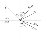
本发明的工作原理如下,隔振屏障的原理是建立在波能的反射、散射的基础上,其实质是非匀质弹性半空间内波的传播问题,即弹性波与土介质中屏障的相互作用问题,由于屏障存在而引起波反射、散射和透射等传递变化规律。当传播中的波遇到两种不同弹性介质的分界面时,一部分入射波反射回第一种介质,另一部分波传递到第二种介质中,这就是弹性波的反射和透射现象。波分可以为横波、纵波、瑞利波等,其中纵波(P波)的发射与透射如图1所示,横波(SV波)的反射与透射如图2所示,入射角为α1,纵波的反射角、透射角分别α2、α3,横波的反射角、透射角分别为α4、α5,根据斯涅尔定律可得
(A1-A2)cosα1+A3 sinα4-A4 cosα3-A5 sinα5=0(A 1 -A 2 ) cos α 1 +A 3 sin α 4 -A 4 cos α 3 -A 5 sin α 5 =0
(A1+A2)sinα1+A3 cosα4-A4 sinα3+A5 cosα5=0(A 1 +A 2 )sinα 1 +A 3 cosα 4 -A 4 sinα 3 +A 5 cosα 5 =0


由这组方程可求得反射波及透射波的振幅。在垂直入射情况下(α1=0),由上式可得反射及透射波的振幅分别

本发明水平埋设空心管隔振屏障与现有隔振技术相比,具有以下优点:Compared with the existing vibration isolation technology, the horizontally buried hollow tube vibration isolation barrier of the present invention has the following advantages:
本发明隔振屏障埋设的混凝土空心管能为周围土体提供足够的支承力,有利于周围土体的稳定性,有效解决了空沟屏障由于稳定性差无法满足隔振屏障对深度要求的问题;本发明通过调整上下层空心管的埋设倾角α(在一定深度条件下,倾角越小,隔振效果越好)以及上下空心管之间的径向间距,能够进一步优化该隔振屏障的隔振效果,在不增加成本的前提下实现更好的隔振性能。The concrete hollow pipe buried in the vibration isolation barrier of the present invention can provide sufficient supporting force for the surrounding soil, which is beneficial to the stability of the surrounding soil, and effectively solves the problem that the empty ditch barrier cannot meet the depth requirement of the vibration isolation barrier due to its poor stability; The present invention can further optimize the vibration isolation of the vibration isolation barrier by adjusting the embedding inclination angle α of the upper and lower hollow tubes (under a certain depth condition, the smaller the inclination angle, the better the vibration isolation effect) and the radial distance between the upper and lower hollow tubes The effect is to achieve better vibration isolation performance without increasing the cost.
波在通过该隔振屏障时需经过混凝土和空气两种介质,本发明由于采用的混凝土、土体与空气三种材料相互之间具有较大的阻抗比,能够较大的减少波能量透过屏障,从而提高了隔振效果。When the wave passes through the vibration isolation barrier, it needs to pass through two media: concrete and air. Since the concrete, soil and air used in the present invention have a relatively large impedance ratio to each other, the transmission of wave energy can be greatly reduced. barrier, thereby improving the vibration isolation effect.
本发明混凝土空心管内部是空心的,与填充沟和排桩相比,其材料用量更少,建造成本更为低廉;本发明隔振屏障所采用的混凝土管节可以在施工前按照设计图纸在工厂预制制作,施工时只需将管节吊装拼接在一起即可,与以往的填充沟相比,施工更加便捷、工期更短;当隔振屏障施工完毕后,开挖沟槽所采用的钢板桩支撑系统可以再次回收利用,有利于进一步减少工程的成本。The interior of the concrete hollow pipe of the present invention is hollow, and compared with filling trenches and row piles, the amount of materials used is less, and the construction cost is lower; It is prefabricated in the factory, and only needs to be hoisted and spliced together during construction. Compared with the previous filling trench, the construction is more convenient and the construction period is shorter; after the construction of the vibration isolation barrier is completed, the steel plate used for excavating the trench The pile support system can be recycled again, which is beneficial to further reduce the cost of the project.
附图说明Description of drawings
图1为P波反射透射原理图;Figure 1 is a schematic diagram of P wave reflection and transmission;
图2为SV波的反射透射原理图;Figure 2 is a schematic diagram of reflection and transmission of SV waves;
图3为本发明水平埋设空心管隔振屏障构造图;Fig. 3 is the structural diagram of the horizontally buried hollow tube vibration isolation barrier of the present invention;
图4是本发明混凝土空心管隔振屏障的平面示意图;Fig. 4 is the schematic plan view of concrete hollow tube vibration isolation barrier of the present invention;
图5是本发明空心管填埋隔振屏障三维示意图;Fig. 5 is a three-dimensional schematic diagram of the hollow tube landfill vibration isolation barrier of the present invention;
图6是常用隔振措施构造及隔振效果对比示意图;Figure 6 is a schematic diagram of the structure of commonly used vibration isolation measures and the comparison of vibration isolation effects;
图7是承插管节连接示意图;Fig. 7 is a schematic diagram of connection of a socket joint;
图8是本发明水平埋设空心管隔振屏障横截面图;Fig. 8 is a cross-sectional view of the horizontally buried hollow pipe vibration isolation barrier of the present invention;
图中,1为混凝土空心管;2为黏土;3为钢板桩;4为压顶梁;5为顶部内支撑;6为中部横梁;7为中部内支撑;8为管节接缝。In the figure, 1 is the concrete hollow pipe; 2 is the clay; 3 is the steel sheet pile; 4 is the top beam; 5 is the top internal support; 6 is the middle beam; 7 is the middle internal support;
具体实施方式detailed description
本发明的具体实施方式如附图所示。The specific embodiment of the present invention is as shown in the accompanying drawings.
如图3所示,本实施例的水平空心管填埋隔振屏障由混凝土空心管及其周围回填压实的黏土组成,所使用的混凝土空心管的直径和长度应针对实际工程进行设计,管道的直径应不小于达到预期隔振效果的最小值,长度应比相邻内支撑之间的间距小20cm以上,影响该隔振屏障效果的重要参数包括空心管直径d、隔振屏障深度H、埋设倾角α、管间径向间距l;各参数的取值范围为:空心管直径d:1~3m;隔振屏障深度H:≥0.6倍瑞利波长;埋设倾角α:30~90度;管间径向间距l:0~0.3d。As shown in Figure 3, the horizontal hollow tube landfill vibration isolation barrier of this embodiment is composed of concrete hollow tubes and backfilled compacted clay around them. The diameter and length of the concrete hollow tubes used should be designed according to the actual project. The diameter should not be less than the minimum value to achieve the expected vibration isolation effect, and the length should be more than 20cm shorter than the distance between adjacent inner supports. The important parameters affecting the effect of the vibration isolation barrier include the diameter of the hollow tube d, the depth of the vibration isolation barrier H, The embedding inclination angle α, the radial distance between the pipes l; the value range of each parameter is: the diameter of the hollow pipe d: 1-3m; the depth H of the vibration isolation barrier: ≥0.6 times the Rayleigh wavelength; the embedding inclination angle α: 30-90 degrees; Radial spacing l between tubes: 0~0.3d.
如图4和5所示,为本实施例隔振屏障的平面与三维空间布置示意图;As shown in Figures 4 and 5, it is a schematic diagram of the plane and three-dimensional space layout of the vibration isolation barrier of this embodiment;
如图6所示为空沟、排桩、填充沟以及水平埋设空心管隔振屏障的构造和隔振效果示意图,所使用的水平埋设空心管隔振屏障其隔振效果非常显著,且与其他隔振方案相比,其建设成本和建造难度都较低。Figure 6 is a schematic diagram of the structure and vibration isolation effect of empty ditch, row of piles, filling ditch, and horizontally buried hollow tube vibration isolation barrier. The vibration isolation effect of the horizontally buried hollow tube vibration isolation barrier is very significant, and it is different from other Compared with the vibration isolation scheme, its construction cost and construction difficulty are lower.
如图7所示为承插管节连接示意图,沟槽开挖完毕后,混凝土管节采用吊车进行安装,吊车从一端向另一端缓慢移动,直至把整段管节拼装完成,管节直接采用承插式接缝,在承口端应先做一下硬性水泥砂浆,在管节套管以后再在承口端空隙内塞以砂浆,以使接头部位紧密贴合,并将内壁表面抹平。Figure 7 is a schematic diagram of the connection of socket pipe joints. After the trench is excavated, the concrete pipe joints are installed by a crane. The crane moves slowly from one end to the other end until the entire pipe joint is assembled, and the pipe joints are directly used For socket joints, hard cement mortar should be made at the socket end first, and then mortar should be filled in the gap at the socket end after the pipe joint is sleeved to make the joints fit closely and smooth the inner wall surface.
图8是本发明水平埋设空心管隔振屏障示意图。当本实施例隔振屏障需开挖较深的沟槽时,为保证槽壁的稳定性,需采用钢板桩3、压顶梁4、顶部内支撑5、中部横梁6和中部内支撑7组成支撑体系,确保整个挖槽工作的顺利进行,且管节在分层埋设时,应先把底部土体夯击密实,并做成与管身弧度密贴的弧形管座后再放置管节。Fig. 8 is a schematic diagram of the horizontally buried hollow tube vibration isolation barrier of the present invention. When the vibration isolation barrier in this embodiment needs to excavate a deep trench, in order to ensure the stability of the trench wall, it is necessary to use steel sheet piles 3, top beams 4, top
下面结合附图对本实施例一种水平空心管填埋隔振屏障的施工工艺作进一步说明:The following is a further description of the construction process of a horizontal hollow tube filling vibration isolation barrier in this embodiment in conjunction with the accompanying drawings:
(1)沿着拟沟槽的轮廓施工一圈钢板桩3,再在钢板桩3的桩顶内侧施工一圈压顶梁4,然后在压顶梁4标高处经螺丝连接顶部内支撑5;(1) Construct a circle of steel sheet piles 3 along the outline of the intended groove, and then construct a circle of pressure beams 4 inside the pile top of the steel sheet piles 3, and then connect the top
(2)下挖到沟槽深度的一半处,在钢板桩3的内侧施工一圈中部横梁6,然后在中部横梁6标高处经螺丝连接中部内支撑7;(2) Dig down to half the depth of the trench, construct a circle of middle beam 6 inside the steel sheet pile 3, and then connect the middle
(3)继续开挖至沟槽的设计标高处;(3) Continue to excavate to the design elevation of the trench;
(4)将管底土层夯击密实,并做成与管身弧度密贴的弧形管座;(4) Compact the soil layer at the bottom of the pipe and make it into an arc-shaped pipe seat that is closely attached to the arc of the pipe body;
(5)使用吊车分段安放底层混凝土空心管节,各管节之间采用承插式接缝形式;(5) Use a crane to place the bottom concrete hollow pipe joints in sections, and use socket joints between the pipe joints;
(6)底层管节全部安装完毕后,在管节上部回填黏土2,夯实做成与管身弧度密贴的弧形地基;(6) After all the bottom pipe joints are installed, backfill
(7)重复步骤(5)安放第二层管节;(7) Repeat step (5) to place the second layer of pipe joints;
(8)重复步骤(6)和(5)直至全部管层安放完成,并注意在管层回填到合适位置处拆除中部内支撑7和中部横梁6;(8) Repeat steps (6) and (5) until all pipe layers are placed, and pay attention to remove the middle
(9)最后拆除压顶梁4和顶部内支撑5,回填土体并压实,拆除和回收钢板桩3。(9) Finally, the top beam 4 and the top
Claims (6)

Priority Applications (1)
| Application Number | Priority Date | Filing Date | Title |
|---|---|---|---|
| CN202110575496.5A CN113216279B (en) | 2021-05-26 | 2021-05-26 | Horizontal hollow pipe landfill vibration isolation barrier and construction process thereof |
Applications Claiming Priority (1)
| Application Number | Priority Date | Filing Date | Title |
|---|---|---|---|
| CN202110575496.5A CN113216279B (en) | 2021-05-26 | 2021-05-26 | Horizontal hollow pipe landfill vibration isolation barrier and construction process thereof |
Publications (2)
| Publication Number | Publication Date |
|---|---|
| CN113216279A CN113216279A (en) | 2021-08-06 |
| CN113216279B true CN113216279B (en) | 2022-12-13 |
Family
ID=77098584
Family Applications (1)
| Application Number | Title | Priority Date | Filing Date |
|---|---|---|---|
| CN202110575496.5A Active CN113216279B (en) | 2021-05-26 | 2021-05-26 | Horizontal hollow pipe landfill vibration isolation barrier and construction process thereof |
Country Status (1)
| Country | Link |
|---|---|
| CN (1) | CN113216279B (en) |
Citations (21)
| Publication number | Priority date | Publication date | Assignee | Title |
|---|---|---|---|---|
| JPH02108730A (en) * | 1988-10-14 | 1990-04-20 | Shimizu Corp | Ground inner wall |
| CN1059770A (en) * | 1990-09-06 | 1992-03-25 | 陆建衡 | Shock insulation and elimination device for high storeyed building construction |
| EP0519575A1 (en) * | 1991-06-20 | 1992-12-23 | Colijn Beheer B.V. | Method of making a foundation pile |
| US5205528A (en) * | 1992-04-17 | 1993-04-27 | John Cunningham | Earthquake-resistant architectural system |
| TW489849U (en) * | 2001-11-21 | 2002-06-01 | Chao-Hung Lin | Isolation structure for lessening earthquake energy |
| TW507800U (en) * | 2001-08-21 | 2002-10-21 | Chao-Hung Lin | Shock-decreasing isolation structure |
| JP2003090386A (en) * | 2001-09-17 | 2003-03-28 | Hirokazu Takemiya | Vibrationproof engineering method |
| RO119845B1 (en) * | 2002-02-13 | 2005-04-29 | Sigma Star Service S.R.L. | Sandwich structure, device comprising the said structure and device network for taking over and damping loads, for controlling under charge behaviour of constructions, systems and equipments |
| JP2006125151A (en) * | 2004-11-01 | 2006-05-18 | Tokyu Construction Co Ltd | Vibration-proofing structure and vibration prevention method in ground |
| CN101012632A (en) * | 2007-01-12 | 2007-08-08 | 中国科学院寒区旱区环境与工程研究所 | Reinforced ventilating heat-proof foundation |
| CN102606670A (en) * | 2012-03-23 | 2012-07-25 | 华东交通大学 | Differential sensing type magnetorheological damper |
| CN104695292A (en) * | 2015-03-26 | 2015-06-10 | 南京工业大学 | Discontinuous vibration reduction and isolation device and forming method |
| CN205530384U (en) * | 2016-04-07 | 2016-08-31 | 铁道第三勘察设计院集团有限公司 | A empty well group and empty well row for subtracting vibration isolation |
| CN109778919A (en) * | 2019-03-25 | 2019-05-21 | 华东交通大学 | A vibration isolation embankment for reducing vibration in railway environment |
| CN109972668A (en) * | 2019-03-29 | 2019-07-05 | 北京市劳动保护科学研究所 | Vibration isolation barrier, preparation method and system for isolating building vibration caused by subway |
| CN110273438A (en) * | 2019-06-28 | 2019-09-24 | 华东交通大学 | A kind of step type vibration isolation ditch barrier and preparation method thereof |
| CN110761132A (en) * | 2019-10-15 | 2020-02-07 | 广州大学 | An assembled vibration isolation barrier |
| CN111021158A (en) * | 2019-12-16 | 2020-04-17 | 北京交通大学 | Honeycomb Periodic Pile Arrangement Vibration Isolation Device |
| CN111910692A (en) * | 2020-09-03 | 2020-11-10 | 华东交通大学 | A multi-row vibration isolation trench barrier structure and evaluation method for vibration isolation effect |
| CN112080971A (en) * | 2020-09-01 | 2020-12-15 | 深圳五联建设工程有限公司 | Construction structure for constructing road on soft soil foundation |
| CN112681163A (en) * | 2020-12-18 | 2021-04-20 | 天津大学 | Inclined pile vibration isolation barrier for reducing vibration induced by subway operation and preparation method thereof |
Family Cites Families (8)
| Publication number | Priority date | Publication date | Assignee | Title |
|---|---|---|---|---|
| DE3579553D1 (en) * | 1984-10-19 | 1990-10-11 | Frankignoul Pieux Armes | DEVICE FOR INSULATING OR DAMPING VIBRATIONS. |
| JP2995253B2 (en) * | 1990-02-28 | 1999-12-27 | 東急建設株式会社 | Roadbed anti-vibration device |
| JP5209830B1 (en) * | 2013-01-07 | 2013-06-12 | 株式会社クックレインボー | Surface vibration isolation structure |
| CN203034495U (en) * | 2013-01-17 | 2013-07-03 | 周凤玺 | Vibration reduction and isolation device used for liquid storage sandstone layer |
| CN204849489U (en) * | 2015-05-29 | 2015-12-09 | 河北建筑工程学院 | Railway roadbed structure with subtract vibration isolation bed course |
| US10151074B2 (en) * | 2015-12-15 | 2018-12-11 | Massachusetts Institute Of Technology | Wave damping structures |
| CN207987633U (en) * | 2017-06-29 | 2018-10-19 | 佛山科学技术学院 | A kind of pvc pipe Railway Vibration vibration insulation structure |
| CN107556044B (en) * | 2017-09-18 | 2020-08-18 | 南京工业大学 | A kind of plate vibration damping and isolation structure and molding preparation method |
-
2021
- 2021-05-26 CN CN202110575496.5A patent/CN113216279B/en active Active
Patent Citations (21)
| Publication number | Priority date | Publication date | Assignee | Title |
|---|---|---|---|---|
| JPH02108730A (en) * | 1988-10-14 | 1990-04-20 | Shimizu Corp | Ground inner wall |
| CN1059770A (en) * | 1990-09-06 | 1992-03-25 | 陆建衡 | Shock insulation and elimination device for high storeyed building construction |
| EP0519575A1 (en) * | 1991-06-20 | 1992-12-23 | Colijn Beheer B.V. | Method of making a foundation pile |
| US5205528A (en) * | 1992-04-17 | 1993-04-27 | John Cunningham | Earthquake-resistant architectural system |
| TW507800U (en) * | 2001-08-21 | 2002-10-21 | Chao-Hung Lin | Shock-decreasing isolation structure |
| JP2003090386A (en) * | 2001-09-17 | 2003-03-28 | Hirokazu Takemiya | Vibrationproof engineering method |
| TW489849U (en) * | 2001-11-21 | 2002-06-01 | Chao-Hung Lin | Isolation structure for lessening earthquake energy |
| RO119845B1 (en) * | 2002-02-13 | 2005-04-29 | Sigma Star Service S.R.L. | Sandwich structure, device comprising the said structure and device network for taking over and damping loads, for controlling under charge behaviour of constructions, systems and equipments |
| JP2006125151A (en) * | 2004-11-01 | 2006-05-18 | Tokyu Construction Co Ltd | Vibration-proofing structure and vibration prevention method in ground |
| CN101012632A (en) * | 2007-01-12 | 2007-08-08 | 中国科学院寒区旱区环境与工程研究所 | Reinforced ventilating heat-proof foundation |
| CN102606670A (en) * | 2012-03-23 | 2012-07-25 | 华东交通大学 | Differential sensing type magnetorheological damper |
| CN104695292A (en) * | 2015-03-26 | 2015-06-10 | 南京工业大学 | Discontinuous vibration reduction and isolation device and forming method |
| CN205530384U (en) * | 2016-04-07 | 2016-08-31 | 铁道第三勘察设计院集团有限公司 | A empty well group and empty well row for subtracting vibration isolation |
| CN109778919A (en) * | 2019-03-25 | 2019-05-21 | 华东交通大学 | A vibration isolation embankment for reducing vibration in railway environment |
| CN109972668A (en) * | 2019-03-29 | 2019-07-05 | 北京市劳动保护科学研究所 | Vibration isolation barrier, preparation method and system for isolating building vibration caused by subway |
| CN110273438A (en) * | 2019-06-28 | 2019-09-24 | 华东交通大学 | A kind of step type vibration isolation ditch barrier and preparation method thereof |
| CN110761132A (en) * | 2019-10-15 | 2020-02-07 | 广州大学 | An assembled vibration isolation barrier |
| CN111021158A (en) * | 2019-12-16 | 2020-04-17 | 北京交通大学 | Honeycomb Periodic Pile Arrangement Vibration Isolation Device |
| CN112080971A (en) * | 2020-09-01 | 2020-12-15 | 深圳五联建设工程有限公司 | Construction structure for constructing road on soft soil foundation |
| CN111910692A (en) * | 2020-09-03 | 2020-11-10 | 华东交通大学 | A multi-row vibration isolation trench barrier structure and evaluation method for vibration isolation effect |
| CN112681163A (en) * | 2020-12-18 | 2021-04-20 | 天津大学 | Inclined pile vibration isolation barrier for reducing vibration induced by subway operation and preparation method thereof |
Non-Patent Citations (3)
| Title |
|---|
| 地屏障在铁路环境振动治理工程中的应用研究;罗锟等;《铁道工程学报》;20090115(第01期);全文 * |
| 某工程治理地铁地面线环境振动及噪声污染问题实施方案成本优化;毛刚等;《城市住宅》;20200625(第06期);全文 * |
| 非对称开挖基坑支撑式围护结构解析解;徐长节等;《岩土力学》;20170621(第08期);全文 * |
Also Published As
| Publication number | Publication date |
|---|---|
| CN113216279A (en) | 2021-08-06 |
Similar Documents
| Publication | Publication Date | Title |
|---|---|---|
| CN110700280B (en) | A diversion device and construction method for foundation pit support construction in narrow areas | |
| CN108442417A (en) | Shock insulation ditch with compaction grouting and varying depth | |
| CN102561406A (en) | Construction method for controlling back soil body deformation of open caisson | |
| CN202559375U (en) | H-shaped steel underground diaphragm wall base pit support structure | |
| CN106869138A (en) | A kind of load retaining wall Retaining Structure with Double-row Piles and its foundation ditch excavation method | |
| CN111851276A (en) | A kind of bridge pier expansion foundation reinforcement structure and construction method thereof | |
| CN113216279B (en) | Horizontal hollow pipe landfill vibration isolation barrier and construction process thereof | |
| CN209798846U (en) | Ditch width gradient type seismic isolation ditch | |
| CN113006085A (en) | Supporting-first-excavating foundation pit supporting system for inclined prefabricated steel piles and construction method of supporting-second-excavating foundation pit supporting system | |
| CN115450169B (en) | River course revetment considering sewage interception pipeline layout and construction method thereof | |
| CN110565666A (en) | Construction method of flat combined sheet pile ground connecting wall type water retaining cofferdam | |
| CN111980074B (en) | Empty trench pile-arranging combined vibration isolation system and construction method | |
| CN204080861U (en) | Inspection-pit between a kind of Novel top pipeline section | |
| CN208183813U (en) | Shock insulation ditch with compaction grouting and varying depth | |
| CN109629556B (en) | Pier variable cross-section vibration isolation pile foundation and construction method thereof | |
| CN113605422A (en) | Construction method of wood-bamboo clay cofferdam | |
| CN111733855A (en) | Construction method of underground diaphragm wall and underground diaphragm wall | |
| CN219219127U (en) | Horizontal landfill rectangular hollow tube vibration isolation barrier device | |
| CN113324097A (en) | Deep groove excavation construction process | |
| CN108166543B (en) | Pile foundation multifunctional pipeline device for ultrasonic detection, underground heat exchange and post grouting | |
| CN115627793B (en) | A vibration isolation pile structure and construction method thereof | |
| JP2008261139A (en) | Seismic isolation structure and seismic isolation construction method | |
| CN116065633B (en) | Combined isolation protection method for subway station support pile construction close to electric power pipe ditch | |
| CN219158994U (en) | A foundation pit support structure for ultra-deep and large-diameter circular pipe-jacking wells in deep soft soil areas | |
| CN114875889B (en) | Staggered crossing grooving method suitable for double-row narrow-distance ground wall construction |
Legal Events
| Date | Code | Title | Description |
|---|---|---|---|
| PB01 | Publication | ||
| PB01 | Publication | ||
| SE01 | Entry into force of request for substantive examination | ||
| SE01 | Entry into force of request for substantive examination | ||
| GR01 | Patent grant | ||
| GR01 | Patent grant |