CN113215721B - Knitting machine and method of use - Google Patents
Knitting machine and method of use Download PDFInfo
- Publication number
- CN113215721B CN113215721B CN202110416040.4A CN202110416040A CN113215721B CN 113215721 B CN113215721 B CN 113215721B CN 202110416040 A CN202110416040 A CN 202110416040A CN 113215721 B CN113215721 B CN 113215721B
- Authority
- CN
- China
- Prior art keywords
- drive
- assembly
- tubes
- drive unit
- slot
- Prior art date
- Legal status (The legal status is an assumption and is not a legal conclusion. Google has not performed a legal analysis and makes no representation as to the accuracy of the status listed.)
- Active
Links
Images


Classifications
-
- D—TEXTILES; PAPER
- D04—BRAIDING; LACE-MAKING; KNITTING; TRIMMINGS; NON-WOVEN FABRICS
- D04C—BRAIDING OR MANUFACTURE OF LACE, INCLUDING BOBBIN-NET OR CARBONISED LACE; BRAIDING MACHINES; BRAID; LACE
- D04C1/00—Braid or lace, e.g. pillow-lace; Processes for the manufacture thereof
- D04C1/06—Braid or lace serving particular purposes
- D04C1/12—Cords, lines, or tows
-
- D—TEXTILES; PAPER
- D04—BRAIDING; LACE-MAKING; KNITTING; TRIMMINGS; NON-WOVEN FABRICS
- D04C—BRAIDING OR MANUFACTURE OF LACE, INCLUDING BOBBIN-NET OR CARBONISED LACE; BRAIDING MACHINES; BRAID; LACE
- D04C3/00—Braiding or lacing machines
- D04C3/40—Braiding or lacing machines for making tubular braids by circulating strand supplies around braiding centre at equal distances
-
- D—TEXTILES; PAPER
- D04—BRAIDING; LACE-MAKING; KNITTING; TRIMMINGS; NON-WOVEN FABRICS
- D04C—BRAIDING OR MANUFACTURE OF LACE, INCLUDING BOBBIN-NET OR CARBONISED LACE; BRAIDING MACHINES; BRAID; LACE
- D04C1/00—Braid or lace, e.g. pillow-lace; Processes for the manufacture thereof
- D04C1/06—Braid or lace serving particular purposes
-
- D—TEXTILES; PAPER
- D04—BRAIDING; LACE-MAKING; KNITTING; TRIMMINGS; NON-WOVEN FABRICS
- D04C—BRAIDING OR MANUFACTURE OF LACE, INCLUDING BOBBIN-NET OR CARBONISED LACE; BRAIDING MACHINES; BRAID; LACE
- D04C3/00—Braiding or lacing machines
- D04C3/40—Braiding or lacing machines for making tubular braids by circulating strand supplies around braiding centre at equal distances
- D04C3/44—Braiding or lacing machines for making tubular braids by circulating strand supplies around braiding centre at equal distances with means for forming sheds by subsequently diverting various threads using the same guiding means
-
- D—TEXTILES; PAPER
- D04—BRAIDING; LACE-MAKING; KNITTING; TRIMMINGS; NON-WOVEN FABRICS
- D04C—BRAIDING OR MANUFACTURE OF LACE, INCLUDING BOBBIN-NET OR CARBONISED LACE; BRAIDING MACHINES; BRAID; LACE
- D04C3/00—Braiding or lacing machines
- D04C3/48—Auxiliary devices
-
- D—TEXTILES; PAPER
- D10—INDEXING SCHEME ASSOCIATED WITH SUBLASSES OF SECTION D, RELATING TO TEXTILES
- D10B—INDEXING SCHEME ASSOCIATED WITH SUBLASSES OF SECTION D, RELATING TO TEXTILES
- D10B2509/00—Medical; Hygiene
- D10B2509/06—Vascular grafts; stents
Landscapes
- Engineering & Computer Science (AREA)
- Textile Engineering (AREA)
- Manufacturing & Machinery (AREA)
- Braiding, Manufacturing Of Bobbin-Net Or Lace, And Manufacturing Of Nets By Knotting (AREA)
Abstract
本文公开了用于形成管状编织物的系统和方法。根据本技术的示例配置的编织系统可包括,例如,上驱动单元,下驱动单元,与上和下驱动单元同轴的心轴,以及在上驱动单元和下驱动单元之间延伸的多个管。每个管可以配置为接收单独的细丝以形成管状编织物,并且上驱动单元和下驱动单元可以同步地抵靠管而作用以上下交叉地通过细丝,以在心轴上形成管状编织物。
Systems and methods for forming tubular braids are disclosed herein. A braiding system configured in accordance with examples of the present technology may include, for example, an upper drive unit, a lower drive unit, a mandrel coaxial with the upper and lower drive units, and a plurality of tubes extending between the upper drive unit and the lower drive unit . Each tube may be configured to receive individual filaments to form a tubular braid, and the upper and lower drive units may act synchronously against the tubes to pass the filaments up and down to form the tubular braid on the mandrel.
Description
本申请是申请号为201780077601.4的分案申请,该母案的申请日为2017年10月14日,发明名称为编织机器和使用方法。This application is a divisional application with the application number 201780077601.4. The application date of the parent case is October 14, 2017. The invention name is a weaving machine and a method of use.
相关申请交叉引用Related Application Cross Reference
本申请要求2016年10月14日提交的题为″编织机器和使用方法″的美国临时申请No.62/408,604和2017年5月19日提交的题为″编织机器和使用方法″的美国临时申请No.62/508,938的优先权,两者均通过引用整体并入本文。This application claims U.S. Provisional Application No. 62/408,604, filed October 14, 2016, entitled "Knitting Machine and Method of Use" and U.S. Provisional Application No. 62/408,604, filed May 19, 2017, entitled "Knitting Machine and Method of Use" Priority to Application No. 62/508,938, both of which are hereby incorporated by reference in their entirety.
技术领域technical field
本技术总体上涉及用于形成细丝的管状编织物的系统和方法。特别地,本技术的一些示例涉及用于通过垂直管的移动形成编织物的系统,每个系统围绕心轴的纵向轴以一系列离散的径向和弧形路径容纳细丝。The present technology generally relates to systems and methods for forming tubular braids of filaments. In particular, some examples of the present technology relate to systems for forming braids by movement of vertical tubes, each system accommodating filaments in a series of discrete radial and arcuate paths around the longitudinal axis of a mandrel.
背景技术Background technique
编织物通常包括交织在一起的许多细丝以形成圆柱形或其他管状结构。这种编织物具有广泛的医疗应用。例如,编织物可以设计成折叠成小导管,以便在微创外科手术中进行展开。一旦从导管展开,一些编织物可在它们所展开于其中的血管或其它身体腔内扩张,例如,阻塞或减缓体液流动,捕获或过滤体液内的颗粒,或取回身体中的血液凝块或其他异物。Braids typically include many filaments intertwined together to form cylindrical or other tubular structures. Such braids have a wide range of medical applications. For example, braids can be designed to fold into small catheters for deployment during minimally invasive surgical procedures. Once deployed from the catheter, some braids can expand within the blood vessel or other body lumen in which they are deployed, for example, to block or slow the flow of bodily fluids, to capture or filter particles within bodily fluids, or to retrieve blood clots or other foreign bodies.
一些用于形成编织物的已知机器通过移动线的线轴来操作,使得从各个线轴放出(paid out)的线彼此上下交叉。然而,这些编织机不适用于需要由具有低拉伸强度的非常细的线构成的编织物的大多数医疗应用。特别是,当线从线轴放出时,它们可能受到可能使线断裂的大的冲击力。其他已知的编织机为每根线提供(secure)配重以拉紧线而不会在编织过程中使它们受到大的冲击力。然后,这些机器使用钩子或其他方式操纵线用于夹紧线以将线编织于彼此之上/之下。这种编织机的一个缺点是它们往往非常慢。此外,由于编织物具有许多应用,因此其设计的规格-例如它们的长度,直径,孔径等等可能变化很大。因此,希望提供一种能够形成具有不同尺寸的编织物的编织机,其使用非常细的细丝,并且比钩型上/下编织机具有更高的速度。Some known machines for forming braids operate by moving spools of thread so that the thread paid out from each spool crosses each other above and below. However, these braiding machines are not suitable for most medical applications that require braids made of very thin wires with low tensile strength. In particular, when the threads are paid out from the spool, they may be subjected to large impact forces which may break the threads. Other known braiding machines provide (secure) weights for each thread to tension the threads without subjecting them to large impact forces during the weaving process. These machines then manipulate the wires using hooks or otherwise for gripping the wires to weave the wires over/under each other. One downside to such braiding machines is that they tend to be very slow. Furthermore, because braids have many applications, the specifications of their design - such as their length, diameter, pore size, etc., can vary widely. Therefore, it would be desirable to provide a knitting machine capable of forming braids of different sizes, using very fine filaments, and having a higher speed than a hook-type over/under knitting machine.
附图说明Description of drawings
参考以下附图可以更好地理解本公开的许多方面。附图中的组件不一定按比例绘制。相反,重点在于清楚地说明本公开的原理。Many aspects of the disclosure can be better understood with reference to the following figures. Components in the figures are not necessarily drawn to scale. Rather, emphasis is placed upon clearly illustrating the principles of the disclosure.
图1是根据本技术的示例配置的编织系统的等距视图。Figure 1 is an isometric view of a weaving system configured in accordance with an example of the present technology.
图2是根据本技术的示例配置的图1中所示的编织系统的管的放大剖视图。2 is an enlarged cross-sectional view of a tube of the braiding system shown in FIG. 1 configured in accordance with an example of the present technology.
图3是根据本技术的示例配置的图1中所示的编织系统的上驱动单元的等距视图。3 is an isometric view of an upper drive unit of the weaving system shown in FIG. 1 configured in accordance with an example of the present technology.
图4A和图4B是根据本技术的示例配置的图3中所示的上驱动单元的外组件的俯视图和放大俯视图。4A and 4B are top and enlarged top views of an outer assembly of the upper drive unit shown in FIG. 3 configured in accordance with an example of the present technology.
图5是根据本技术的示例配置的图3中所示的上驱动单元的内组件的俯视图。5 is a top view of inner components of the upper drive unit shown in FIG. 3 configured in accordance with an example of the present technology.
图6是根据本技术的示例配置的图3中所示的上驱动单元的一部分的放大等距视图。6 is an enlarged isometric view of a portion of the upper drive unit shown in FIG. 3 configured in accordance with an example of the present technology.
图7是根据本技术的示例配置的图1中所示的编织系统的下驱动单元的等距视图。7 is an isometric view of a lower drive unit of the weaving system shown in FIG. 1 configured in accordance with an example of the present technology.
图8A-8H是根据本技术的示例的图3中所示的上驱动单元在形成编织结构的方法中的各个阶段的放大示意图。8A-8H are enlarged schematic illustrations of various stages in a method of forming a braided structure of the upper drive unit shown in FIG. 3 in accordance with an example of the present technology.
图9是根据本技术的示例配置的编织系统控制器的用户界面的显示。9 is a display of a user interface of a knitting system controller configured in accordance with examples of the present technology.
图10是根据本技术的示例配置的图1中所示的编织系统的心轴的一部分的等轴测图。10 is an isometric view of a portion of the mandrel of the braiding system shown in FIG. 1 configured in accordance with an example of the present technology.
具体实施例specific embodiment
本技术一般涉及用于从多个细丝形成编织结构的系统和方法。在多个示例中,根据本技术的编织系统可包括上驱动单元,沿中心轴与上驱动单元同轴对齐的下驱动单元,以及在上驱动单元和下驱动单元之间延伸并被约束在上和下驱动单元以内的多个管。每根管可以容纳连接到配重上的单根细丝的末端。细丝可以从管延伸到与中心轴对齐的心轴。在某些示例中,上和下驱动单元可同步动作以使管的子集(i)朝向中心轴线径向向内移动,(ii)从中心轴线径向向外移动,(iii)并围绕中心轴线旋转地移动。因此,上和下驱动单元可以操作以移动管的子集-以及保持在其中的细丝-经过的管另一个子集,以在心轴上形成例如″上/下″编织结构。因为线包含在管内并且上和下驱动单元在管的上部和下部同步地起作用,所以管可以快速地移动通过彼此以形成编织物。这是对不同步地移动管的上部和下部的系统的显著改进。此外,由于使用多个配重提供张力,本系统允许使用非常细的细丝来形成编织物。因此,在编织过程中,细丝不会受到可能会破坏它们的大的冲击力。The present technology generally relates to systems and methods for forming braided structures from a plurality of filaments. In various examples, a knitting system in accordance with the present technology may include an upper drive unit, a lower drive unit coaxially aligned with the upper drive unit along a central axis, and a and multiple tubes inside the lower drive unit. Each tube can accommodate the end of a single filament attached to a counterweight. A filament may extend from the tube to a mandrel aligned with the central axis. In some examples, the upper and lower drive units can act synchronously to move a subset of tubes (i) radially inward toward the central axis, (ii) radially outward from the central axis, (iii) and around the central axis. The axis moves rotationally. Thus, the upper and lower drive units are operable to move a subset of the tubes - and the filaments held therein - past another subset of the tubes to form, for example, an "up/down" braided structure on the mandrel. Because the wire is contained within the tube and the upper and lower drive units act synchronously on the upper and lower parts of the tube, the tubes can move quickly past each other to form the braid. This is a significant improvement over systems that move the upper and lower parts of the tube asynchronously. In addition, the present system allows the use of very fine filaments to form a braid due to the use of multiple weights to provide tension. Therefore, during the weaving process, the filaments are not subjected to large impact forces that could break them.
如本文所用,术语″垂直″,″横向″,″上″和″下″可以指考虑图中所示的取向的编织系统中的特征的相对方向或位置。例如,″上″或″最上″可以指代比另一特征更靠近页面顶部设置位置的特征。然而,这些术语应该被广义地解释为包括具有其他取向的半导体器件,例如倒置或倾斜取向,其中顶部/底部,高于/低于,之上/之下,上/下,和左/右可以根据取向进行互换。As used herein, the terms "vertical", "transverse", "upper" and "lower" may refer to the relative orientation or position of features in a weaving system considering the orientation shown in the Figures. For example, "top" or "topmost" may refer to a feature that is positioned closer to the top of the page than another feature. However, these terms should be interpreted broadly to include semiconductor devices having other orientations, such as inverted or oblique orientations, in which top/bottom, above/below, above/below, above/bottom, and left/right can be Swap according to orientation.
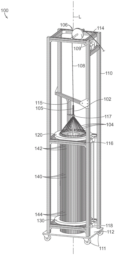
图1是根据本技术配置的编织系统100(″系统100″)的等距视图。系统100包括框架110,耦接到框架110的上驱动单元120,耦接到框架110的下驱动单元130,在上驱动单元120和下驱动单元130(统称为″驱动单元120,130″)之间延伸的多个管140(例如,细长壳体)和心轴102。在一些示例中,驱动单元120,130和心轴102沿中心轴L(例如,纵向轴)同轴对齐。在图1所示的示例中,管140相对于中心轴线L对称地布置,其纵向轴平行于中心轴线L。如图所示,管140围绕中心轴L布置成圆形阵列。也就是说,管140可以各自与中心轴L等距地径向间隔开,并且可以共同形成圆柱形状。在其他示例中,管140的纵向轴可以不与中心轴L垂直对齐(例如,平行于中心轴L)。例如,管140可以布置成圆锥形状,使得管140的纵向轴相对于中心轴L成角度,并与中心轴L相交。在其他示例中,管140可以以″扭曲″形状布置,其中管140的纵向轴相对于中心轴L成角度,但是不与中心轴L相交(例如,管的顶端可以相对于中心轴线L从管的底端成角度地偏移)。1 is an isometric view of a weaving system 100 ("
框架110通常可包括用于支撑和容纳系统100的部件的金属(例如,钢,铝等)结构。更具体地,例如,框架110可包括支撑上驱动单元120的上支撑结构116,支撑下驱动单元130的下支撑结构118,底座112和顶部114。在一些示例中,驱动单元120,130直接(例如,通过螺栓,螺钉,等)分别连接到上支撑结构116和下支撑结构118。在一些示例中,底座112可以配置成支撑管140的全部或一部分。在图1所示的示例中,系统100包括连接到框架110的底座112的轮子111,因此可以是便携式系统。在其他示例中,底座112可以永久地附接到表面(例如,地板),使得系统100不是便携式的。
系统100操作以编织加载的细丝104,以从心轴102径向延伸到管140。如图所示,每个管140可在其中容纳单个细丝104。在其他示例中,仅管140的子集容纳细丝。在一些示例中,细丝104的总数是容纳细丝104的管140的总数的一半。也就是说,相同的细丝104可以具有两个端部,并且两个不同的管140可以容纳相同细丝104的不同端部(例如,在细丝104缠绕或以其他方式固定到心轴102之后)。在其他示例中,细丝104的总数与容纳细丝104的管140的数量相同。
每个细丝104由固定到细丝104的下部的配重张紧。例如,图2是单个管140的放大剖视图。在图2所示的示例中,细丝104包括连接到(例如,系在,缠绕等)位于管140中的配重241的端部207。配重141可以具有圆柱形或其他形状,并且配置成随着在编织过程中放出细丝104,在管140内平滑地滑动。管140还可包括上边缘部分(例如,边缘)245,其是圆形的或以其他方式配置成允许细丝104从管140平稳地放出。如图所示,管140具有圆形横截面形状,并且完全包围配重241和设置在其中的细丝104。在其他示例中,管140可以具有其他横截面形状,例如正方形,矩形,椭圆形,多边形等,并且可以不完全包围或围绕配重241和/或细丝104。例如,管140可包括槽,开口和/或其他特征,同时仍提供细丝104的必要容纳和约束。Each
管140限制配重241和细丝104的横向或″摆动″运动,以抑制这些部件沿着细丝104的整个长度的显著摇摆和缠结。相比较于细丝和/或张紧装置沿其全长不受约束的系统,这使得系统100能够以更高的速度操作。具体地,如果没有将暂停或停留时间结合到该过程中使得细丝可以稳定(settle),则未受约束的细丝可能摇摆并且彼此缠结。在许多应用中,细丝104是非常细的线,在没有本技术的全长约束和同步的情况下,另外需要显著的暂停来进行稳定。在一些示例中,细丝104全部连接到相同的配重以在系统100内提供均匀的张力。然而,在其他示例中,细丝104中的一些或全部可以连接到不同的配重以提供不同的张力。值得注意的是,可以使配重241非常小以以在细丝104上施加低张力,从而允许编织细(例如,小直径)和脆弱的细丝。
再次参考图1,并且如下面参考图3-8H进一步详细描述的,驱动单元120,130控制管140的移动和位置。驱动单元120,130被配置为驱动管140相对于中心轴线L在一系列离散的径向和弧形路径中,其以在心轴102上形成编织结构105(例如,编织管状编织物;“编织物105″)的方式移动细丝104。特别地,管140各自具有靠近上驱动单元120的上端部142和靠近下驱动单元130的下端部144。驱动单元120,130同步工作以同时沿相同的路径或至少基本相似的空间路径驱动每个单独管140的上端部142和下端部144(统称为″端部142,144″)。通过同步驱动各个管140的两个端部142,144,管140的摇摆量或其他不期望的运动量受到很大限制。结果,系统100减少或甚至消除编织过程期间的允许管稳定的暂停,这使得系统100能够以比传统系统更高的速度操作。在其他示例中,驱动单元120,130可以相对于管130不同地布置。例如,驱动单元120,130可以设置在不与管的端部142,144相邻的两个位置处。优选地,驱动单元具有垂直间隔(例如,布置得足够靠近管140的端部142,144),其为管140提供稳定性并抑制管140的摇摆或其他不希望的运动。Referring again to FIG. 1 , and as described in further detail below with reference to FIGS. 3-8H , the
在一些示例中,驱动单元120,130基本相同并且包括一个或多个机械连接,使得它们相同地移动(例如,同步)。例如,驱动单元120,130中的一个可以是有源单元,而驱动单元120,130中的另一个可以是由有源单元驱动的从单元。在其他示例中,取代机械连接,耦合到驱动单元120,130的电子控制系统被配置成在空间和时间上以相同的顺序移动管140。在某些示例中,在管140相对于中心轴线L成圆锥形布置的情况下,驱动单元120,130可以具有相同的部件但具有不同的直径。In some examples, drive
在图1所示的示例中,心轴102附接到拉动机构106,拉动机构106被配置成相对于管140沿中心轴L移动(例如,升高)心轴102。拉动机构106可包括轴108(例如,缆线,线,刚性结构等)将心轴102连接到用于移动心轴102的致动器或电机(未示出)。如图所示,拉动机构106还可包括耦接到框架110的一个或多个引导件109(例如,轮子,滑轮,滚子等),用于引导轴108并将来自致动器或电机的力引导到心轴102。在操作期间,心轴102可以从管140上抬起离开,以延伸用于在心轴102上创建编织物105的表面。在一些示例中,可以改变心轴102升高的速率,以改变编织物105的特性(例如,增加或减少细丝104的编织角度(间距)以及因此的编织物105的孔的尺寸)。完成的编织物的最终长度取决于管140中的细丝104的可用长度,编织物的间距以及心轴102的可用长度。In the example shown in FIG. 1 , the
在一些示例中,心轴102可沿其长度具有纵向凹槽,以例如抓住细丝104。心轴102还可包括用于在编织过程期间阻止心轴102相对于中心轴L旋转的部件。例如,心轴102可包括纵向键槽(例如,通道)和可滑动地容纳在键槽中的固定锁定销,其在心轴102升高时保持心轴102的定向。心轴102的直径在大端上仅由驱动单元120,130的尺寸被限制,并且在小端上由正在被编织的细丝104的数量和直径限制。在一些示例中,在心轴102的直径小(例如,小于约4mm)的情况下,系统100可以进一步包括耦合到心轴102的一个或多个配重。配重可以使心轴102处于显著的张力下并且防止细丝104在编织过程中纵向地使心轴102变形。在一些示例中,配重可以配置成进一步抑制心轴102的旋转和/或替换键槽和锁定销的使用以抑制旋转。In some examples, the
系统100还可包括通过臂115耦接到框架110的套管(例如,环)117。心轴102通过套管117延伸,并且细丝104各自通过心轴102和套管117之间的环形开口延伸。在一些示例中,套管117的内径仅略大于心轴102的外径。因此,在操作期间,套管117迫使细丝104抵靠心轴102,使得编织物105抵靠心轴102紧密地拉动。在一些示例中,套管117可具有可调节的内径以容纳不同直径的细丝。类似地,在某些示例中,套管117的垂直位置可以改变,以调节细丝104会聚以形成编织物105的点。
图3是根据本技术的示例配置的图1中所示的上驱动单元120的等距视图。上驱动单元120包括围绕中心轴线L(图1)同心布置的外组件350和内组件370(统称为″组件350,370″)。外组件350包括(i)外槽(例如,凹槽)354,(ii)与相应的外槽354对齐和/或位置设置在相应的外槽354内的外驱动构件(例如,柱塞)356,以及(iii)配置为通过外槽354径向向内移动外驱动构件356的外驱动机构。外槽354的数量可以等于系统100中的管140的数量,并且外槽354被配置成在其中接收管140。在某些示例中,外组件350包括48个外槽354。在其他示例中,外组件350可具有不同数量的外槽354,例如12个槽,24个槽,96个槽,或任何其他优选偶数个槽。外组件350还包括上板351a和与上板351a相对的下板351b。上板351a至少部分地限定外组件350的上表面。在一些示例中,下板351b可以附接到框架110的上支撑结构116。FIG. 3 is an isometric view of the
在图3所示的示例中,外组件350的外驱动机构包括位于上板和下板351a,351b之间的第一外凸轮环352a和第二外凸轮环352b(统称为″外凸轮环352″)。第一外凸轮环电机358a可以是电动电机,其被配置成驱动第一外凸轮环352a以使第一组外驱动构件356径向向内移动,从而径向向内移动第一组管140。同样,第二外凸轮环电机358b被配置成使第二外凸轮环352b旋转,以使第二组外驱动构件356径向向内移动,从而径向向内移动第二组管140。更具体地,第一外凸轮环电机358a可以耦接到一个或多个小齿轮357a,该小齿轮357a被配置成配合第一外凸轮环352a上的相应第一轨道359a,并且第二外凸轮环电机358b可耦接到一个或多个小齿轮357b,小齿轮357b被配置成与第二外凸轮环352b上的相应的第二轨道359b配合。在一些示例中,如图3所示,第一和第二轨道359a,359b(统称为″轨道359″)分别仅部分地围绕第一和第二外凸轮环352a,352b的周边延伸。因此,在这样的示例中,外凸轮环352不被配置为围绕中心轴L完全旋转。相反,外凸轮环352仅围绕中心轴L移动相对较小的弧长(例如,约1°-5°,或约5°-10°)。在操作中,外凸轮环352可以沿第一方向和第二方向(例如,通过使电机反转)旋转通过相对小的角度。在其他示例中,轨道359围绕外凸轮环352的周边的较大部分(例如整个周边)延伸,并且外凸轮环352可以围绕中心轴L更完全地(例如,完整地)旋转。In the example shown in FIG. 3, the outer drive mechanism of the
内组件370包括(i)内槽(例如,凹槽)374,(ii)内驱动构件(例如,柱塞)376,其与相应的内槽374对准和/或位置设置在相应的内槽374内,以及(iii)内驱动机构,配置成使内驱动构件376通过内槽374径向向外移动。如图所示,内槽374的数量可以等于外槽354的数量的一半(例如,24个内槽374),使得内槽374被配置成在其中接收管140的子集(例如,一半)。外槽354与内槽374的比率在其他示例中可以是不同的,例如一对一。特别地,在图3所示的示例中,内槽374与管140和交替间隔的外槽354中的一些对齐,并且如下面进一步详细描述的,外凸轮环352中的一个可以被旋转以移动对齐的管140进入内槽374。内组件370还可包括下板371b,下板371b可旋转地耦接到内支撑构件373。例如,在一些示例中,可旋转耦接包括在内支撑构件373和下板371b之间形成圆形凹槽中的的多个轴承。内组件370还可包括与下板371b相对的上板371a,并且至少部分地限定内组件370的上表面。
在图3所示的示例中,内驱动机构包括位于上板371a和下板371b之间的内凸轮环372。内凸轮环电机378被配置成驱动(例如,旋转)内凸轮环372以使所有内驱动构件376径向向外移动,从而使位于内槽374中的管140径向向外移动。内凸轮环电机378可大致类似于第一和第二外凸轮环电机358a,358b(统称为″外凸轮环电机358″)。例如,内凸轮环电机378可以连接到一个或多个小齿轮,该小齿轮被配置成与在内凸轮环372上的相应轨道配合(例如,匹配)(在图3中被模糊;在图6中最佳地示出)。在一些示例中,轨道仅围绕内凸轮环372的内周边的一部分延伸,并且内凸轮环电机378可沿第一方向和第二相反方向旋转,以仅驱动内凸轮环372通过围绕中心轴L的相对小的弧长(例如,约1°-5°,约5°-10°或约10°-20°)。In the example shown in FIG. 3, the inner drive mechanism includes an
内组件370还包括内组件电机375,内组件电机375被配置成使内组件370相对于外组件350旋转。该旋转允许内槽374旋转成与不同的外槽354对齐。内组件电机375的操作可大致类似于外凸轮环电机358和内凸轮环电机378的操作。例如,内组件电机375可旋转一个或多个小齿轮,该小齿轮耦接到安装在下板371b上和/或上板371a上的轨道。The
通常,上驱动单元120被配置成以三种不同的运动驱动管140:(i)通过外组件350的外凸轮环352的旋转径向向内(例如,从外槽354到内槽374)运动;(ii)通过内组件370的内凸轮环372的旋转径向向外(例如,从内槽374到外槽354)运动;并且(iii)通过内组件370的旋转周向地运动。此外,如下面参考图9更详细地解释的,在一些示例中,这些运动可以是机械独立的,并且系统控制器(未示出;例如,数字计算机)可以通过用户界面接收来自用户的输入,该输入表示用于这些运动的一个或多个操作参数以及心轴102(图1)的运动。例如,系统控制器可以驱动在驱动单元120,130中的四个电机中的每一个(例如,外凸轮环电机358,内凸轮环电机378和内组件电机375),并带有闭环轴旋转反馈。系统控制器可以将参数传递到各种电机(例如,通过处理器),从而允许手动和/或自动控制管140和心轴102的运动以控制编织物105的形成。以这种方式,系统100可以是带有参数的,并且可以在不修改系统100的情况下制造许多不同形式的编织物。在其他示例中,驱动单元120,130的各种运动被机械地排序,使得转动单个轴对驱动单元120,130在整个循环进行索引(indexes)。Generally,
参考图4A-6描述了组件350,370的驱动机构的进一步细节。特别地,图4A,图4B是上驱动单元120的外组件350的示例的俯视图和放大俯视图。上板351a和第一外凸轮环352a未被描绘,以更清楚地示出了外组件350的操作。一起参考图4A和4B,下板351b具有限定中心开口464的内边缘463。多个壁部分462围绕下板351b周向布置,并径向向内延伸超过下板351b的内边缘463。每对相邻的壁部分462在中心开口464中限定外槽354中的一个。壁部分462可以紧固到下板351b(例如,使用螺栓,螺钉,焊接等)或者与下板351b一体成型。在其他示例中,壁部分462的全部或一部分可以在上板351a上而不是在外组件350的下板351b上。Further details of the drive mechanisms of the
第二外凸轮环352b包括具有周期性(例如,振荡)形状的内表面465,其包括多个峰467和谷469。在所示示例中,内表面465具有平滑的正弦形状,而在在其他示例中,内表面465可以具有其他周期性形状,例如锯齿形状。第二外凸轮环352b可旋转地耦接到下板351b,使得第二外凸轮环352b和下板351b可相对于彼此旋转。例如,在一些示例中,可旋转耦接包括多个轴承,这些轴承设置在下板351b和第二外凸轮环352b之间形成的第一圆形通道中(在图4A中4B中模糊)。在所示示例中,第二外凸轮环352b包括第二圆形通道461,用于通过多个轴承将第二外凸轮环352b可旋转地耦接到第一外凸轮环352a。在一些示例中,第一圆形通道可与第二圆形通道461基本相同。虽然图4A和4B中未示出,但如图6所示,第一外凸轮环352a可与第二外凸轮环352b基本相同。The second
如图4A和4B进一步所示,外驱动构件356的位置设置在相邻的壁部分462之间。每个外驱动构件356是相同的,尽管外驱动构件356中的交替间隔的的一些在外组件350内的方向不同。例如,相邻的外驱动构件356可以相对于由下板351b限定的平面垂直翻转。更具体地,参考图4B,外驱动构件356各自包括耦接到推动部分494的主体部分492。推动部分494配置成配合(例如,接触和推动)位置设置在外槽354内的管。As further shown in FIGS. 4A and 4B , the location of the
参照图4B,主体部分492还包括不与外凸轮环352配合的台阶部分491,以及仅与外凸轮环352中的一个配合的延伸部分493。例如,第一组外驱动构件456a具有延伸部分493,该延伸部分493连续地接触第二外凸轮环352b的内表面465,但是不接触第一外凸轮环352a的内表面。特别地,第一组外驱动构件456a的延伸部分493在其向第一外凸轮环352a下方延伸时,不与第一外凸轮环352a的内表面接触。同样,如图6中最佳所示,第二组外驱动构件456b具有延伸部分493,其连续地接触第一外凸轮环352a的内表面,但不接触第二外凸轮环352b。特别地,第二组外驱动构件456b的延伸部分493在其向第二外凸轮环352b的上方延伸时,不接触第二外凸轮环352b的内表面465。以这种方式,每个外凸轮环352被配置成仅驱动一组(例如,一半)外驱动构件356。此外,如图4B所示,外驱动构件356还可包括轴承495或其他用于在外驱动构件356和外凸轮环352之间提供平滑耦接的合适机构。Referring to FIG. 4B , the
第一组外驱动构件456a可以在交替间隔的,相邻的一对壁部分462之间耦接到下板351b。类似地,在一些示例中,当组装外组件350时(例如,当上板351a被耦接到下板351b时),第二组外驱动构件456b可以耦接到上板351a,并位置设置在交替间隔的,相邻的一对壁部分462之间。通过将第二组外驱动构件456b安装到上板351a,相同的安装系统可以用于每个外驱动构件356。例如,外驱动构件356可以可滑动地连接到框架496,该框架496通过多个螺钉497连接到上板或下板351a,351b中的一个上。在其他示例中,所有外驱动构件356可以附接(例如,通过框架496和螺钉497)到下板351b或上板351a。如图4A和4B进一步所示,偏置构件498(例如,弹簧)在每个外驱动构件356和相应的框架496之间延伸,并且向外驱动构件356施加径向向外的偏置力。The first set of
在操作中,外驱动构件356通过外凸轮环352的周期性内表面的旋转被径向向内驱动,并且通过偏置构件498被径向向外返回。例如,在图4A和4B中,每个外驱动构件356处于径向缩回位置。在径向缩回位置,第二外凸轮环352b的内表面465的谷469与第一组外驱动构件456a对齐。在该位置,外驱动构件356的延伸部分493相比于内表面465的峰467位于或更靠近谷469。为了使第一组外驱动构件456a径向向内移动,第二外凸轮环352b的旋转使内表面465的峰467移动成与第一组外驱动构件456a径向对齐。由于偏置构件498的向外力促使延伸部分493与内表面465连续接触,随着内表面465从槽469旋转到峰467时,延伸部分493径向向内移动。为了随后将第一组外驱动构件456a返回到缩回位置,第二外凸轮环352b旋转以使谷469与第一组外驱动构件456a径向对齐。当该旋转发生时,偏置构件498的径向向外偏置力将第一组外驱动构件456a缩回到由谷469提供的空间中。第二组外驱动构件456b和第一外凸轮环352a的操作可以以基本相似或相同的方式进行。In operation,
图5是上驱动单元120的内组件370的俯视图。上板371a未被示出以更清楚地示出内组件370的操作。如图所示,下板371b具有外边缘583和内组件370包括多个壁部分582,这些壁部分582围绕下板371b周向布置并径向向外延伸超过外边缘583。每对相邻的壁部分582限定一个内槽374。壁部分582可以固定在下板371b上(例如,使用螺栓,螺钉,焊接等)或与下板371b一体成型。在其他示例中,至少一些壁部分582位于上板371a而不是内组件370的下板371b上。FIG. 5 is a top view of the
内凸轮环372包括具有周期性(例如,振荡)形状的外表面585,其包括多个峰587和谷589。在所示示例中,外表面585具有锯齿形状,而在在其他示例中,外表面585可以具有其他周期性形状,例如平滑的正弦曲线形状。内凸轮环372通过例如设置在下板371b和内凸轮环372之间的第一圆形通道(在图5的俯视图中被模糊)中设置的多个滚珠轴承可旋转地连接到下板371b。在所示示例中,内凸轮环372包括第二圆形通道581,用于通过例如多个滚珠轴承将内凸轮环372可旋转地耦接到上板371a。在一些示例中,第一圆形通道可以与第二圆形通道581基本相同。内凸轮环372因此可以相对于上板371a和下板371b旋转。
如图5中进一步所示,内驱动构件376在相邻壁部分582之间耦接到下板371b。每个内驱动构件376是相同的,并且内驱动构件376可以与外驱动构件356相同(图4A和4B)。例如,如上所述,每个内驱动构件376可以具有包括台阶部分491和延伸部分493的主体492,并且内驱动构件376每个可以可滑动地耦接到安装到下板371b的框架496。类似地,在每个内驱动构件376和它们相应的框架496之间延伸的偏置构件498对内驱动构件376施加径向向内的偏置力。其结果是,内驱动构件376的延伸部分493连续地接触内凸轮环372的外表面585。As further shown in FIG. 5 ,
在操作中,外周期表面585的旋转驱动内驱动构件376径向向外,而偏置构件498径向向内缩回内驱动构件376。例如,如图5所示,内驱动构件376处于径向缩回位置。在径向缩回位置,内凸轮环372的外表面585的谷589与内驱动构件376径向对齐,使得内驱动构件376的延伸部分593相对于外表面585的峰587处于或更接近谷589。为了使内驱动构件376径向向外移动,内凸轮环372旋转以使外表面585的峰587移动至与内驱动构件376径向对齐。由于偏置构件498推动延伸部分493与外表面585连续接触,随着外表面585从谷589旋转到峰587,内驱动构件376被连续地径向向内推动。为了随后将内驱动构件576返回到径向缩回位置,内凸轮环372被旋转以使谷589移动至与内驱动构件576径向对齐。当发生这种旋转时,由偏置构件598提供的径向向内偏置力将内驱动构件376向内缩回到由谷589提供的空间中。In operation, rotation of the outer
值得注意的是,系统100中的每个驱动构件由凸轮环的旋转致动,该凸轮环向所有驱动构件提供一致且同步的致动力。相反,在传统的系统中,其中细丝通过单独控制的致动器单独地或小组地致动,如果一个致动器与另一个致动器不同步,则存在缠结细丝的可能性。Notably, each drive member in
图6是图3中所示的上驱动单元120的一部分的放大等距视图,其示出了组件350,370的同步(例如,往复)动作。图6中未示出外组件350的上板351a和内组件370的上板371a,以更清楚地说明这些部件的操作。在所示示例中,所有管140的位置都设置在外组件350的外槽354中。因此,每个外驱动构件356处于缩回位置,使得在外槽中存在用于管140的空间。更具体地说,如图所示,(i)第二外凸轮环352b的内表面465的谷469(部分遮挡;图4A和4B所示)与第一组外驱动构件456a径向对齐,(ii)第一外凸轮环352a的周期性内表面665的谷669与第二组外驱动构件456b径向对齐,以及(iii)耦接到外驱动构件356的偏置构件498具有最小长度(例如,完全压缩的位置)。相反,在所示示例中,内驱动构件376处于完全伸出位置,其中内驱动构件376与内凸轮环372的外表面585接触,相对于谷589,位于或更接近外表面585的的峰部587。在该位置,耦接到内驱动构件376的偏置构件498具有最大长度(例如,完全展开位置)。FIG. 6 is an enlarged isometric view of a portion of
如图6中进一步所示,第一组外驱动构件456a与内槽374径向对齐。在该位置,第一组外驱动构件456a可使在对应于第一组外驱动构件456a的外槽354中的管140移动到内槽374。为此,第二外凸轮环电机358b(图3)可被致动以旋转(例如,顺时针或逆时针)第二外凸轮环352b,从而使内表面465的峰467与第一组外驱动构件456a对齐。因此,内表面465径向向内驱动第一组外驱动构件456a。同时,内凸轮环电机378可被致动以使内凸轮环372旋转(例如,沿逆时针方向),以使内凸轮环372的外表面585的谷589与内驱动构件376对齐。内凸轮环372的这种运动使内驱动构件376径向向内缩回。以这种方式,组件350,370可以被配置为将管140保持在良好控制的空间中。更具体地,在外驱动构件356径向向内移动的同时,内驱动构件376缩回相应的量以维持管140的空间,或反之亦然。这使管140保持以由系统100的控制系统确定的离散的,可预测模式移动。As further shown in FIG. 6 , the first set of
图7是根据本技术的示例配置的图1中示出的下驱动单元130的等距视图。下驱动单元130具有与上面参考图3-6详细描述的上驱动单元120基本相同或同样的部件和功能。例如,下部驱动单元130包括外组件750和内组件770。外组件750可包括(i)外槽,(ii)与相应外槽对齐和/或位置设置在相应外槽内的外驱动构件,和(iii)外驱动机构,其配置成使外驱动构件通过外槽径向向内移动等。类似地,内组件770可包括(i)内槽,(ii)内驱动构件,其与相应的内槽对齐和/或位置设置在相应的内槽内,和内驱动机构,其被配置成使内驱动构件通过内槽径向向外移动等。FIG. 7 is an isometric view of the
驱动单元120,130的内驱动机构(例如,内凸轮环)在空间上和时间上以基本相同的顺序移动,以沿着相同或基本类似的空间路径驱动每个单独管140的上部和下部。同样地,驱动单元120,130的外驱动机构(外凸轮环)在空间和时间上以基本相同的顺序移动。在一些示例中,使用机械连接来同步驱动单元120,130。例如,如图7所示,千斤顶轴713可以机械地耦接驱动单元120,130的内和外驱动机构的相应部件。更具体地,千斤顶轴713机械地将上驱动单元120的第一外凸轮环352a耦接到下驱动单元130中的匹配的第一外环凸轮,以及将上驱动单元120的第二外凸轮环352b耦接到下驱动单元130中的匹配的第二外环凸轮。千斤顶轴713(图7中未示出)可以类似地将内凸轮环372和内组件370(例如,用于旋转内组件370)连接到下驱动单元130中的相应部件。在两个驱动单元120,130上包括单独的电机避免了千斤顶轴中的扭转搅动(whip),同时确保驱动单元120,130之间的运动同步。在一些示例中,驱动120,130中的一个中的电机是闭环控制的,而另一个驱动单元120,130中的电机充当从属的。The inner drive mechanisms (eg, inner cam rings) of the
一般地,驱动单元120,130一次移动两组管140中的一组(以及位置设置在那些管内的细丝)。每组由交替间隔的的管140组成,因此由管140的总数的一半组成。当驱动单元120,130移动一组时,该组被移动(i)径向向内,(ii)旋转经过另一组,然后(iii)径向向外移动。然后将该次序应用于另一组,旋转发生在相反方向。也就是说,一组沿顺时针方向绕中心轴L(图1)移动,而另一组沿逆时针方向绕中心轴L移动。每组的所有管140同时移动,并且当一组运动时,另一组是静止的。重复该一般循环以在心轴102上形成编织物105(图1)。Generally, the
图8A-8H是更具体地示出了根据本技术的示例的在形成编织结构(例如,编织物105)的方法中的各个阶段处的上驱动单元120内的六个管的移动的示意图。在参考上驱动单元120内的管的运动的同时,所示的管的运动在下驱动单元130中基本相同或甚至同样。此外,尽管图8A-8H中仅示出了六个管为了便于解释和理解,本领域技术人员将容易理解,六个管的移动代表任何数量的管(例如,24个管,48个管,96个管或其他数量的管)的移动。8A-8H are schematic diagrams illustrating more particularly the movement of six tubes within
首先参见图8A,六个管(例如,管140)分别标记为1-6并且最初都分别位于外组件350的单独的外槽354中,标记为A-F。位于标记为A,C,E的外槽354中的第一组管840a(包括管1,3和5)与内组件370的标记为X-Z的相应内槽374径向对齐。相对地,位于标记为B,D和F的外槽354中的第二组管840b(包括管2,4和6)不与内组件370的任何内槽374径向对齐。用于外槽354的附图标记A-F,用于内槽374的X-Z和用于管的1-6在图8A-8H的每一个中重现,以便示出这些部件的相对运动。Referring first to FIG. 8A, the six tubes (eg, tube 140) are labeled 1-6 and are each initially located in a single
接下来参照图8B,第一组管840a从外组件350的外槽354径向向内移动到内组件370的内槽374。特别地,与第一组管840a对齐的外驱动构件356径向向内移动并径向向内驱动第一组管840a进入内槽374。在一些示例中,同时,内驱动构件376可通过内槽374径向向内缩回,以为第一组管840a提供空间以被移动到内槽374中。以这种方式,外组件350和内组件370彼此一致地移动,以操纵为第一组管840a提供的空间。Referring next to FIG. 8B , the first set of
接下来,如图8C所示,内组件370沿第一方向(例如,沿箭头CW表示的顺时针方向)旋转,以使内槽374与不同组的外槽354对齐。在图8C所示的示例中,内槽374与两个槽之外的不同组的外槽354对齐。例如,虽然标记为Y的内槽374最初与标记为C的外槽374对齐(图8A),但在旋转之后,标记为Y的内槽374与标记为E的外槽354对齐。因此,该步骤将第一组管840a中的细丝置于第二组管840b中的细丝的下方。Next, as shown in FIG. 8C ,
接下来参考图8D,第一组管840a从内组件370的内槽374径向向外移动到外组件350的外槽354。具体地,内驱动构件376通过内槽374径向向外移动并径向向外驱动第一组管840a进入与内槽374对齐的外槽354。在一些示例中,同时,外驱动构件356通过对齐的外槽354径向向外缩回以为第一组管840a提供移动到外槽354中的空间。值得注意的是,如图8B-8D所示,第二组管840b在第一组管840a被移动的每个步骤中是静止的。Referring next to FIG. 8D , the first set of
接下来,如图8E所示,内组件370沿第二方向(例如,沿箭头CCW所示的逆时针方向)旋转,以使内槽374与不同的外槽354对齐,即,那些容纳第二组管840b的外槽。在其他示例中,内组件370可以沿第一方向旋转,以使内槽374与不同的外槽354对齐。在图8E所示的示例中,内组件370被旋转以使每个内槽374与距离一个槽的不同的外槽对齐(例如,相邻的外槽354)。例如,虽然标记为X的内槽374先前与标记为C的外槽354对齐(图8D),但在旋转之后,标记为X的内槽374与标记为B的外槽354对齐。在旋转内组件370之后,第二组管840b从外组件350的外槽354径向向内移动到内组件370的内槽374。特别地,与第二组管840b对齐的外驱动构件356通过外槽354径向向内移动并径向向内驱动第二组管840b进入内槽374,同时内驱动构件376通过内槽374径向向内缩回,以为第二组管840b提供空间以被移动到内槽374中。Next, as shown in FIG. 8E , the
接下来参考图8F,内组件370沿第二方向(例如,沿箭头CCW所示的顺时针方向)旋转,以使内槽374与不同组的外槽354对齐。在图8F所示的示例中,内组件370旋转以使每个内槽374与两个槽之外的不同外槽354对齐。例如,虽然标记为Y的内槽374先前与标记为D的外槽354对齐(图8E),但是在旋转之后,标记为Y的内槽374与标记为B的外槽354对齐。因此,该步骤将第二组管840b中的细丝置于第一组管840a的细丝下方。Referring next to FIG. 8F ,
接下来,如图8G所示,第二组管840b从内组件370的内槽374径向向外移动到外组件350的外槽354。特别地,内驱动构件376通过内槽374径向向外移动并径向向外驱动第一组管840a进入与内槽374对齐的外槽354。在一些示例中,同时,外驱动构件356可通过外槽354径向向外缩回。以用于为第一组管840a提供移动到外槽354中的空间。值得注意的是,如图8E-8G所示,第一组管840a在第二组被移动的每个步骤中是静止的。Next, as shown in FIG. 8G , the second set of
最后,如图8H所示,内组件370沿第一方向(例如,沿箭头CCW所示的顺时针方向)旋转,以使内槽374与不同的外槽354对齐,即,容纳第一组管840a的那些外槽。在其他示例中,内组件370沿第二方向旋转,以使内槽374与不同的外槽354对齐。在图8H所示的示例中,内组件370的旋转使内槽374与一个槽之外的不同的外槽354对齐(例如,相邻的外槽354)。例如,虽然标记为Y的内槽先前与标记为C的外槽354对齐(图8G),但在旋转之后,标记为Y的内槽374与标记为B的外槽354对齐。因此,内组件370和外组件350可以返回到图8A所示的初始位置。相反,第一组管840a中的每个管已经相对于图8A中所示的初始位置沿第一方向(例如,沿顺时针方向旋转两个外槽354)旋转,并且第二组管840b中的每个管已经相对于图8A的初始位置沿第二方向旋转(例如,沿逆时针方向旋转两个外槽354)。Finally, as shown in FIG. 8H ,
随着第一和第二组管840a,840b一和容纳在其中的细丝一重复地彼此相互通过,以相反方向旋转,在相对于另一组径向向外的通过和相对于另一组径向向内通过之间顺序地交替,随后可以重复图8A-8H所示的步骤以在心轴上形成圆柱形编织物。本领域技术人员将认识到,在不脱离本技术的范围的情况下,可以改变旋转方向,每个旋转的距离等。As the first and second sets of
图9是可用于控制系统100(图1)的用户界面900的屏幕截图以及在心轴102上形成的所得编织物105的特性。在用户界面900内示出了多个可点击的,可推动的或以其他方式可配合的按钮,指示器,开关(toggles)和/或用户元件。例如,用户界面900可以包括多个元件,每个元件表示所得到的编织物105的期望和/或预期特性。在一些示例中,可以为一个或多个区域(例如,图示的7个区域)选择特性,每个区域对应于形成在心轴102上的编织物105的不同垂直部分。更具体地,元件910可以表示沿着心轴或编织物的长度的区域的长度(例如,以cm为单位),元件920可以表示每cm的梭(pick)的数量(交叉的数量),元件930可以表示梭计数(例如,总梭计数),元素940可以表示该过程的速度(例如,在每分钟形成的梭),元件950可以表示编织线数。在一些示例中,如果用户输入区域的特定特性,则可以约束或自动选择其他特性的一些或全部。例如,″每厘米梭数″和区域″长度″的某一数量的用户输入可以约束或确定″每厘米梭数″的可能的数字。用户界面还可以包括可选元件960用于在编织物105在特定区域中形成之后暂停系统100,以及可选择元件970,用于在形成特定区域期间保持心轴静止(例如,允许手动轻推(jogging)心轴102而不是自动的)。另外,用户界面可以包括用于轻推工作台的元件980a和980b,用于分别向上或向下轻推(例如,升高或降低)心轴102的元件985a和985b,元件990a和990b(例如,一组保存的编织物特性)用于分别加载概况和运行选定的概况,以及指示器995,用于表示运行(例如,编织过程的全部或一部分)完成。FIG. 9 is a screenshot of a
在一些示例中,例如,较低的梭计数提高了柔韧性,而较高的梭计数增加了编织物105的纵向刚度。因此,系统100有利地允许梭计数(以及编织物105的其他特性)在编织物105的特定长度内变化,以提供可变的柔韧性和/或纵向刚度。例如,图10是心轴102和在其上形成的编织物105的放大视图。编织物105或心轴102可包括第一区域Z1,第二区域Z2和第三区域Z3,每个区域具有不同的特性。如图所示,例如,第一区域Z1可以具有比第二和第三区域Z2和Z3更高的梭计数,并且第二区域Z2可以具有比第三区域Z3更高的梭计数。因此,编织物105可以在每个区域中具有变化的柔韧性以及孔径。In some examples, for example, lower shuttle counts increase flexibility, while higher shuttle counts increase the longitudinal stiffness of
在下面的例子中阐述了本技术的几个方面。Several aspects of the technology are illustrated in the following examples.
1.一种编织系统,包括:1. A weaving system comprising:
上驱动单元;upper drive unit;
下驱动单元;Lower drive unit;
与所述上和下驱动单元同轴的心轴;an arbor coaxial with said upper and lower drive units;
在所述上驱动单元和所述下驱动单元之间延伸的多个管,其中各个管被配置成接收单独的细丝,并且其中所述上驱动单元和所述下驱动单元同步地抵靠在所述管上作用。a plurality of tubes extending between the upper drive unit and the lower drive unit, wherein each tube is configured to receive an individual filament, and wherein the upper drive unit and the lower drive unit synchronously abut against the The tube acts on it.
2.根据例子1所述的编织系统,其中所述管被约束在所述上驱动单元和下驱动单元以内,并且其中所述上驱动单元和所述下驱动单元抵靠所述管作用以(i)径向向内驱动所述管,(ii)径向向外驱动所述管,和(iii)使管相对于所述心轴旋转。2. The braiding system of example 1, wherein the tube is constrained within the upper and lower drive units, and wherein the upper and lower drive units act against the tube to ( i) driving the tube radially inward, (ii) driving the tube radially outward, and (iii) rotating the tube relative to the mandrel.
3.根据例子1或2所述的编织系统,其中所述管包括第一组管和第二组管,并且其中所述上驱动单元和所述下驱动单元抵靠所述管作用以相对于所述第二组管旋转所述第一组管。3. The braiding system of example 1 or 2, wherein the tubes comprise a first set of tubes and a second set of tubes, and wherein the upper drive unit and the lower drive unit act against the tubes relative to The second set of tubes rotates the first set of tubes.
4.如例子3所述的编织系统,其中所述第一组和第二组管各包括管总数的一半。4. The braiding system of example 3, wherein the first and second sets of tubes each comprise half of the total number of tubes.
5.根据例子1-4中的任一项所述的编织系统,其中各个管包括靠近所述上驱动单元的唇部,所述唇部具有圆形边缘,该圆形边缘被配置为可滑动地配合单个细丝。5. The braiding system of any one of examples 1-4, wherein each tube includes a lip adjacent the upper drive unit, the lip having a rounded edge configured to slide to fit a single filament.
6.根据例子1-5中的任一项所述的编织系统,其中所述上驱动单元和下驱动单元基本相同。6. The weaving system of any of examples 1-5, wherein the upper and lower drive units are substantially identical.
7.根据例子1-6中的任一项所述的编织系统,其中-7. The braiding system of any one of examples 1-6, wherein -
所述上驱动单元包括(a)外组件,包括(i)外槽,(ii)外驱动构件,和(iii)外驱动机构,其被配置成移动所述外驱动构件;和(b)内组件,包括(i)内槽,(ii)内驱动构件,和(iii)内驱动机构,其被配置成移动所述内驱动构件;The upper drive unit includes (a) an outer assembly including (i) an outer tank, (ii) an outer drive member, and (iii) an outer drive mechanism configured to move the outer drive member; and (b) an inner an assembly comprising (i) an inner tank, (ii) an inner drive member, and (iii) an inner drive mechanism configured to move the inner drive member;
下驱动单元包括(a)外组件,包括(i)外槽,(ii)外驱动构件,和(iii)外驱动机构,其被配置成移动所述外驱动构件;和(b)内组件,包括(i)内槽,(ii)内驱动构件,和(iii)内驱动机构,其被配置成移动所述内驱动构件;和The lower drive unit includes (a) an outer assembly including (i) an outer tank, (ii) an outer drive member, and (iii) an outer drive mechanism configured to move the outer drive member; and (b) an inner assembly, comprising (i) an inner slot, (ii) an inner drive member, and (iii) an inner drive mechanism configured to move the inner drive member; and
各个管被限制在各自的所述内槽和/或外槽中。Each tube is confined in a respective said inner and/or outer groove.
8.根据例子7所述的编织系统,其中-8. The weaving system of example 7, wherein -
所述上驱动单元的所述外槽与所述上驱动单元的所述外驱动构件径向对齐,以及所述上驱动单元的所述外驱动机构被配置成使所述外驱动构件通过所述外槽径向向内移动;The outer slot of the upper drive unit is radially aligned with the outer drive member of the upper drive unit, and the outer drive mechanism of the upper drive unit is configured to pass the outer drive member through the The outer groove moves radially inward;
所述上驱动单元的所述内槽与所述上驱动单元的所述内驱动构件径向对齐,以及所述上驱动单元的所述内驱动机构被配置成使所述内驱动构件通过所述内槽径向向外移动;The inner slot of the upper drive unit is radially aligned with the inner drive member of the upper drive unit, and the inner drive mechanism of the upper drive unit is configured to pass the inner drive member through the The inner groove moves radially outward;
所述下驱动单元的所述外槽与所述下驱动单元的所述外驱动构件径向对齐,以及所述下驱动单元的所述外驱动机构被配置成使所述外驱动构件通过所述外槽径向向内移动;和The outer slot of the lower drive unit is radially aligned with the outer drive member of the lower drive unit, and the outer drive mechanism of the lower drive unit is configured to pass the outer drive member through the the outer groove moves radially inward; and
所述下驱动单元的所述内槽与所述下驱动单元的所述内驱动构件径向对齐,以及所述下驱动单元的所述内驱动机构被配置成使所述内驱动构件通过所述内槽径向向外移动。The inner slot of the lower drive unit is radially aligned with the inner drive member of the lower drive unit, and the inner drive mechanism of the lower drive unit is configured to pass the inner drive member through the The inner slot moves radially outward.
9.根据例子7或8所述的编织系统,其中所述上驱动单元和下驱动单元的外槽的数量是所述上驱动单元和下驱动单元的内槽的数量的两倍。9. The weaving system of example 7 or 8, wherein the number of outer grooves of the upper and lower drive units is twice the number of inner grooves of the upper and lower drive units.
10.根据例子7-9中任一项所述的编织系统,其中-10. The weaving system according to any one of examples 7-9, wherein -
所述上驱动单元的所述外组件还包括外偏置构件,所述外偏置构件耦接到所述外驱动构件的相应的一个并且被配置成向所述外驱动构件施加径向向外的力;The outer assembly of the upper drive unit further includes outer biasing members coupled to respective ones of the outer drive members and configured to apply a radially outward force to the outer drive members. force;
所述上驱动单元的所述内组件还包括内偏置构件,所述内偏置构件耦接到所述内驱动构件的相应的一个并且被配置成向所述内驱动构件施加径向向内的力;The inner assembly of the upper drive unit also includes an inner biasing member coupled to a respective one of the inner drive members and configured to apply a radially inward force to the inner drive members. force;
所述下驱动单元的所述外组件还包括外偏置构件,所述外偏置构件耦接到所述外驱动构件的相应的一个并且被配置成向所述外驱动构件施加径向向外的力;和The outer assembly of the lower drive unit further includes outer biasing members coupled to respective ones of the outer drive members and configured to apply a radially outward force to the outer drive members. force; and
所述下驱动单元的所述内组件还包括内偏置构件,所述内偏置构件耦接到所述内驱动构件的相应的一个并且被配置成向所述内驱动构件施加径向向内的力。The inner assembly of the lower drive unit further includes an inner biasing member coupled to a respective one of the inner drive members and configured to apply a radially inward force to the inner drive members. force.
11.根据例子7-10中任一项所述的编织系统,其中-11. The weaving system according to any one of examples 7-10, wherein -
所述上驱动单元的所述内组件相对于所述上驱动单元的所述外组件可旋转;the inner assembly of the upper drive unit is rotatable relative to the outer assembly of the upper drive unit;
所述下驱动单元的所述内组件相对于所述下驱动单元的所述外组件可旋转;和the inner assembly of the lower drive unit is rotatable relative to the outer assembly of the lower drive unit; and
所述下驱动单元和上驱动单元的所述内组件被配置成同步旋转。The inner components of the lower and upper drive units are configured to rotate synchronously.
12.根据例子7-11中任一项所述的编织系统,其中-12. The weaving system according to any one of examples 7-11, wherein-
所述上驱动单元的所述外驱动机构包括(i)第一上外凸轮环,其被配置成使第一组所述上驱动单元的所述外驱动构件径向向内移动;以及(ii)第二上外凸轮环,其被配置成使第二组所述上驱动单元的所述外驱动构件径向向内移动;The outer drive mechanism of the upper drive unit includes (i) a first upper outer cam ring configured to move the outer drive members of a first set of the upper drive unit radially inwardly; and (ii ) a second upper outer cam ring configured to move said outer drive members of a second set of said upper drive units radially inwardly;
所述上驱动单元的所述内驱动机构包括上内凸轮环,其被配置成使所述上驱动单元的所述内驱动构件径向向外移动;The inner drive mechanism of the upper drive unit includes an upper inner cam ring configured to move the inner drive member of the upper drive unit radially outward;
所述下驱动单元的所述外驱动机构包括(i)第一下外凸轮环,其被配置成使第一组所述下驱动单元所述外驱动构件的径向向内移动;以及(ii)第二下外凸轮环,其被配置成使第二组所述下驱动单元的所述外驱动构件径向向内移动;和The outer drive mechanism of the lower drive unit includes (i) a first lower outer cam ring configured to move radially inwardly a first set of the outer drive members of the lower drive unit; and (ii ) a second lower outer cam ring configured to move said outer drive members of a second set of said lower drive units radially inwardly; and
所述下驱动单元的所述内驱动机构包括下内凸轮环,其被配置成使所述下驱动单元的所述内驱动构件径向向外移动。The inner drive mechanism of the lower drive unit includes a lower inner cam ring configured to move the inner drive member of the lower drive unit radially outward.
13.根据例子12所述的编织系统,其中-13. The weaving system of example 12, wherein -
所述第一上外凸轮环和所述第一下外凸轮环基本相同并同步一起移动;said first upper outer cam ring and said first lower outer cam ring are substantially identical and move together synchronously;
所述第二上外凸轮环和所述第二下外凸轮环基本相同并同步一起移动;以及said second upper outer cam ring and said second lower outer cam ring are substantially identical and move together synchronously; and
所述上内凸轮环和所述下内凸轮环基本相同并同步一起移动。The upper inner cam ring and the lower inner cam ring are substantially identical and move together synchronously.
14.根据例子12或13所述的编织系统,其中-14. The weaving system of example 12 or 13, wherein -
所述第一组所述上驱动单元的所述外驱动构件包括交替间隔的所述外驱动构件,以及所述第二组所述上驱动单元的所述外驱动构件包括不同的交替间隔的所述外驱动构件;和Said first set of said outer drive members of said upper drive unit comprises alternately spaced said outer drive members, and said second set of said outer drive members of said upper drive unit comprises different alternately spaced said outer drive members. external drive components; and
所述下驱动单元的所述外驱动构件的所述第一组包括交替间隔的所述外驱动构件,以及所述下驱动单元的所述外驱动构件的所述第二组包括不同的交替间隔的所述外驱动构件。The first set of the outer drive members of the lower drive unit includes alternating intervals of the outer drive members, and the second set of the outer drive members of the lower drive unit includes different alternating intervals of the outer drive member.
15.根据例子12-14中任一项所述的编织系统,其中-15. The braiding system of any one of examples 12-14, wherein -
所述第一上外凸轮环与所述第二上外凸轮环基本相同,并可旋转地耦接于所述第二上外凸轮环;以及the first upper outer cam ring is substantially identical to the second upper outer cam ring and is rotatably coupled to the second upper outer cam ring; and
所述第一下外凸轮环与所述第二下外凸轮环基本相同,并可旋转地耦接于所述第二下外凸轮环。The first lower outer cam ring is substantially identical to the second lower outer cam ring and is rotatably coupled to the second lower outer cam ring.
16.根据例子12-15中任一项所述的编织系统,其中-16. The braiding system of any one of examples 12-15, wherein -
所述第一上外凸轮环具有朝向径向向内的表面,所述表面具有周期性的形状,所述表面与所述上驱动单元的所述外驱动构件的所述第一组连续接触;said first upper outer cam ring has a radially inwardly facing surface having a periodic shape, said surface being in continuous contact with said first set of said outer drive members of said upper drive unit;
所述第二上外凸轮环具有朝向径向向内的表面,所述表面具有周期性的形状,所述表面与所述上驱动单元的所述外驱动构件的所述第二组连续接触;said second upper outer cam ring has a radially inwardly facing surface having a periodic shape, said surface being in continuous contact with said second set of said outer drive members of said upper drive unit;
所述上内凸轮环具有朝向径向向外的表面,所述表面具有周期性的形状,所述表面与所述上驱动单元的所述内驱动构件连续接触;said upper inner cam ring has a radially outward facing surface having a periodic shape, said surface being in continuous contact with said inner drive member of said upper drive unit;
所述第一下外凸轮环具有朝向径向向内的表面,所述表面具有周期性的形状,所述表面与所述下驱动单元的所述外驱动构件的所述第一组连续接触;said first lower outer cam ring has a radially inwardly facing surface having a periodic shape, said surface being in continuous contact with said first set of said outer drive members of said lower drive unit;
所述第二上外凸轮环具有朝向径向向内的表面,所述表面具有周期性的形状,所述表面与所述下驱动单元的所述外驱动构件的所述第二组连续接触;以及said second upper outer cam ring has a radially inwardly facing surface having a periodic shape, said surface being in continuous contact with said second set of said outer drive members of said lower drive unit; as well as
所述下内凸轮环具有朝向径向向外的表面,所述表面具有周期性形状,所述表面与所述下驱动单元的所述内驱动构件连续接触。The lower inner cam ring has a radially outward facing surface having a periodic shape, the surface being in continuous contact with the inner driving member of the lower driving unit.
17.根据例子7-16任一项所述的编织系统,其中-17. The weaving system according to any one of examples 7-16, wherein -
所述上驱动单元的所述外驱动机构包括上外凸轮环,所述上外凸轮环被配置成使所述上驱动单元的所述外驱动构件径向向内移动;The outer drive mechanism of the upper drive unit includes an upper outer cam ring configured to move the outer drive member of the upper drive unit radially inwardly;
所述上驱动单元的所述内驱动机构包括上内凸轮环,所述上内凸轮环被配置成使所述上驱动单元的所述内驱动构件径向向外移动;The inner drive mechanism of the upper drive unit includes an upper inner cam ring configured to move the inner drive member of the upper drive unit radially outward;
所述下驱动单元的所述外驱动机构包括下外凸轮环,所述下外凸轮环被配置成使所述下驱动单元的所述外驱动构件径向向内移动;以及The outer drive mechanism of the lower drive unit includes a lower outer cam ring configured to move the outer drive member of the lower drive unit radially inward; and
所述下驱动单元的所述内驱动机构包括下内凸轮环,所述下内凸轮环被配置成使所述下驱动单元的所述内驱动构件径向向外移动。The inner drive mechanism of the lower drive unit includes a lower inner cam ring configured to move the inner drive member of the lower drive unit radially outward.
18.根据例子17所述的编织系统,其中所述上外凸轮环和所述下外凸轮环机械同步以一起移动,并且其中所述上内凸轮环和所述下内凸轮环机械同步以一起移动。18. The knitting system of example 17, wherein the upper outer cam ring and the lower outer cam ring are mechanically synchronized to move together, and wherein the upper inner cam ring and the lower inner cam ring are mechanically synchronized to move together move.
19.一种编织系统,包括:19. A weaving system comprising:
外组件包括(i)中心开口,(ii)第一外凸轮,(iii)第二外凸轮,其位置设置为相邻于所述第一外凸轮并且沿纵向轴与所述第一外凸轮同轴对齐,(iv)相对于所述纵向轴径向延伸的外槽,和(v)外驱动机构;The outer assembly includes (i) a central opening, (ii) a first outer cam, (iii) a second outer cam positioned adjacent to and co-located with the first outer cam along the longitudinal axis. axially aligned, (iv) an outer groove extending radially relative to said longitudinal axis, and (v) an outer drive mechanism;
在所述外组件的所述中心开口中的内组件,所述内组件包括(i)内凸轮,(ii)相对于所述纵向轴径向延伸的内槽,(iii)和内驱动机构;和an inner assembly in said central opening of said outer assembly, said inner assembly comprising (i) an inner cam, (ii) an inner slot extending radially relative to said longitudinal axis, (iii) and an inner drive mechanism; and
限制在所述内槽和/或外槽内的多个管,a plurality of tubes confined within said inner tank and/or outer tank,
其中,所述外驱动机构被配置成(i)旋转所述第一外凸轮以将第一组所述管从所述外槽径向向内驱动到所述内槽,以及(ii)旋转所述第二外凸轮以将第二组所述管从所述外槽径向向内驱动到所述内槽,以及wherein said outer drive mechanism is configured to (i) rotate said first outer cam to drive a first set of said tubes radially inwardly from said outer groove to said inner groove, and (ii) rotate said first outer cam said second outer cam to drive a second set of said tubes radially inwardly from said outer groove to said inner groove, and
其中,所述内驱动机构被配置成(i)旋转所述内凸轮以将所述第一组管或第二组管从所述内槽径向向外移动到所述外槽,以及(ii)相对于所述外组件旋转所述内组件。wherein the inner drive mechanism is configured to (i) rotate the inner cam to move the first or second set of tubes radially outward from the inner slot to the outer slot, and (ii ) rotate the inner assembly relative to the outer assembly.
20.根据例子19所述的系统,还包括:20. The system of example 19, further comprising:
沿所述纵轴延伸的心轴;和a mandrel extending along said longitudinal axis; and
多个细丝,其中每个细丝从所述心轴径向延伸到单个管,使得所述细丝的末端部分在所述单个管内。A plurality of filaments, wherein each filament extends radially from the mandrel to a single tube such that an end portion of the filament is within the single tube.
21.根据例子20所述的系统,其中每个细丝的末端部分连接到配重。21. The system of example 20, wherein an end portion of each filament is connected to a counterweight.
22.根据例子20或21所述的系统,其中所述单个管是第一单个管,并且其中所述细丝还从所述心轴径向延伸到第二单个管,使得所述细丝的第二末端部分在所述第二单个管内。22. The system of example 20 or 21, wherein the single tube is a first single tube, and wherein the filament also extends radially from the mandrel to a second single tube such that the A second end portion is within the second single tube.
23.根据例子20-22中任一项所述的系统,其中,当所述管被所述外驱动机构和内驱动机构的一系列径向和旋转运动驱动时,所述细丝围绕所述心轴被编织。23. The system of any one of examples 20-22, wherein the filament surrounds the The mandrel is braided.
24.根据例子20-23中任一项所述的系统,其中,所述心轴被配置成沿着所述纵向轴移动。24. The system of any of examples 20-23, wherein the mandrel is configured to move along the longitudinal axis.
25.根据例子20-24中任一项所述的系统,其中,所述第一外凸轮和所述第二外凸轮基本相同,并且每个都具有朝向径向向内的表面,所述表面具有平滑的正弦曲线形状。25. The system of any one of examples 20-24, wherein the first outer cam and the second outer cam are substantially identical and each have a radially inwardly facing surface, the surface Has a smooth sinusoidal shape.
26.根据例子20-25中任一项所述的系统,其中,所述内凸轮具有朝向径向向外的表面,所述表面具有锯齿形状。26. The system of any one of examples 20-25, wherein the inner cam has a radially outwardly facing surface having a serrated shape.
27.一种形成管状编织物的方法,包括:27. A method of forming a tubular braid comprising:
驱动具有中心轴的第一凸轮,以使第一组管径向向内朝向所述中心轴移动;driving a first cam having a central axis to move the first set of tubes radially inwardly toward said central axis;
使所述第一组管围绕所述中心轴在第一方向上旋转;rotating the first set of tubes about the central axis in a first direction;
驱动第二凸轮与所述第一凸轮同轴对齐,使所述第一组管径向向外远离所述中心轴移动;driving a second cam in coaxial alignment with said first cam to move said first set of tubes radially outward away from said central axis;
驱动第三凸轮与所述第一凸轮同轴对齐,使第二组管径向向内朝向所述中心轴移动;driving a third cam in coaxial alignment with said first cam to move the second set of tubes radially inwardly towards said central axis;
使所述第二组管沿与所述第一方向相反的第二方向绕所述中心轴旋转;以及rotating the second set of tubes about the central axis in a second direction opposite the first direction; and
驱动所述第二凸轮使所述第二组管径向向外远离所述中心轴移动。Driving the second cam moves the second set of tubes radially outward away from the central axis.
28.根据例子27的方法,其中所述第一和第二组管中的每个管连续地配合细丝。28. The method of example 27, wherein each tube of the first and second sets of tubes continuously fits a filament.
29.根据例子28的方法,其中每细丝由于配重而处于拉伸状态。29. The method of example 28, wherein each filament is in tension due to a counterweight.
30.根据例子28或29所述的方法,还包括:30. The method of example 28 or 29, further comprising:
约束所述第一和第二组管使得所述管不在平行于所述中心轴的方向上移动;和constraining the first and second sets of tubes such that the tubes do not move in a direction parallel to the central axis; and
沿着所述中心轴线将心轴远离所述管移动,其中所述心轴连续地配合每根所述细丝。A mandrel is moved away from the tube along the central axis, wherein the mandrel successively engages each of the filaments.
31.根据例子30所述的方法,还包括约束所述心轴使得所述心轴基本上不绕所述中心轴旋转。31. The method of example 30, further comprising constraining the mandrel such that the mandrel does not substantially rotate about the central axis.
32.根据例子27-31中任一项所述的方法,其中-32. The method according to any one of examples 27-31, wherein-
驱动所述第二凸轮使所述第一组管径向向外移动包括将所述第一组管移动到径向位置,在所述径向位置中,所述第一组管和第二组管中的每个管与所述中心轴径向等距间隔;以及Driving the second cam to move the first set of tubes radially outward includes moving the first set of tubes to a radial position in which the first set of tubes and the second set of tubes each of the tubes is radially equidistant from the central axis; and
驱动所述第二凸轮以使所述第二组管径向向外移动包括将所述第二组管移动到所述径向位置。Driving the second cam to move the second set of tubes radially outward includes moving the second set of tubes to the radial position.
33.根据例子27-32中任一项所述的方法,其中-33. The method according to any one of examples 27-32, wherein-
驱动所述第一凸轮使所述第一组管径向向内移动包括使所述第一凸轮的内表面与第一驱动构件配合,所述第一驱动构件与所述第一组管相配合;Driving the first cam to move the first set of tubes radially inwardly includes engaging an inner surface of the first cam with a first drive member cooperating with the first set of tubes ;
驱动所述第二凸轮使所述第一组管径向向外移动包括使所述第二凸轮的外表面与第二驱动构件配合,所述第二驱动构件与所述第一组管相配合;Driving the second cam to move the first set of tubes radially outward includes engaging an outer surface of the second cam with a second drive member cooperating with the first set of tubes ;
驱动所述第三凸轮使所述第二组管径向向内移动包括使所述第三凸轮的内表面与第三驱动构件配合,所述第三驱动构件与所述第二组管相配合;以及Driving the third cam to move the second set of tubes radially inwardly includes engaging an inner surface of the third cam with a third drive member cooperating with the second set of tubes ;as well as
驱动所述第二凸轮以使所述第二组管径向向外移动包括使所述第二凸轮的所述外表面与所述第二驱动构件配合,所述第二驱动构件与所述第二组管相配合。Driving the second cam to move the second set of tubes radially outward includes engaging the outer surface of the second cam with the second drive member that engages the first The two sets of tubes match.
34.根据例子27-33中任一项所述的方法,还包括:34. The method of any one of examples 27-33, further comprising:
在驱动所述第一凸轮使所述第一组管移动的同时,驱动所述第二凸轮为所述第一组管提供径向向内移动的空间;while driving the first cam to move the first set of tubes, driving the second cam provides space for the first set of tubes to move radially inward;
在驱动所述第二凸轮使所述第一组管移动的同时,驱动所述第一凸轮为所述第二组管提供径向向外移动的空间;While driving the second cam to move the first set of tubes, driving the first cam provides space for the second set of tubes to move radially outward;
在驱动所述第三凸轮使所述第二组管移动的同时,驱动所述第二凸轮为所述第二组管提供径向向内移动的空间;和actuating the second cam provides room for radially inward movement of the second set of tubes while driving the third cam to move the second set of tubes; and
在驱动所述第二凸轮使所述第二组管移动的同时,驱动所述第三凸轮为所述第二组管提供径向向外移动的空间。While driving the second cam moves the second set of tubes, driving the third cam provides space for the second set of tubes to move radially outward.
35.一种形成管状编织物的方法,包括:35. A method of forming a tubular braid comprising:
配合多个管的第一组管的上端部分,以将所述第一组管从上驱动单元的外组件径向向内驱动至内组件,同时同步地配合所述第一组管的下端部分,以将所述第一组管从下驱动单元的外组件径向向内驱动至内组件;engaging upper end portions of a first set of tubes to drive said first set of tubes radially inwardly from an outer assembly of an upper drive unit to an inner assembly while synchronously engaging lower end portions of said first set of tubes , to drive the first set of tubes radially inward from the outer assembly of the lower drive unit to the inner assembly;
同步旋转所述上和下驱动单元的所述内组件,以沿第一方向旋转所述第一组管;synchronously rotating the inner assemblies of the upper and lower drive units to rotate the first set of tubes in a first direction;
配合所述第一组管的所述上端部分以将所述第一组管从所述上驱动单元的所述内组件径向向外驱动至所述外组件,同时同步地配合所述第一组管的所述下端部分以将所述第一组管从所述下驱动单元的所述内组件径向向外驱动到所述外组件;engaging the upper end portion of the first set of tubes to drive the first set of tubes radially outward from the inner assembly of the upper drive unit to the outer assembly while synchronously engaging the first grouping said lower end portion of tubes to drive said first set of tubes radially outward from said inner assembly of said lower drive unit to said outer assembly;
配合所述多个管的第二组管的上端部分,以将所述第二组管从所述上驱动单元的外组件径向向内驱动到所述内组件,同时同步地配合所述第二组管的下端部分以将所述第二组管从所述下驱动单元的外组件径向向内驱动到内组件;engaging upper end portions of a second set of tubes of the plurality of tubes to drive the second set of tubes radially inwardly from the outer assembly of the upper drive unit to the inner assembly while synchronously engaging the first the lower end portion of the two sets of tubes to drive the second set of tubes radially inwardly from the outer assembly of the lower drive unit to the inner assembly;
同步旋转所述上和下驱动单元的所述内组件,使所述第二组管沿与所述第一方向相反的第二方向旋转;以及synchronously rotating the inner assemblies of the upper and lower drive units to rotate the second set of tubes in a second direction opposite to the first direction; and
配合所述第二组管的所述上端部分,以将所述第二组管从所述上驱动单元的所述内组件径向向外驱动到所述外组件,同时同步地配合所述第二组管的所述下端部分以将所述第二组管从所述下驱动单元的所述内组件径向向外驱动到所述外组件。engaging the upper end portion of the second set of tubes to drive the second set of tubes radially outward from the inner assembly of the upper drive unit to the outer assembly while synchronously engaging the first The lower end portion of the two sets of tubes is configured to drive the second set of tubes radially outward from the inner assembly of the lower drive unit to the outer assembly.
36.根据例子35所述的方法,还包括:在将所述第一组管从所述下和上驱动单元的所述内组件径向向外驱动到所述外组件之后,沿所述第二方向同步旋转所述内组件。36. The method of example 35, further comprising: after driving the first set of tubes radially outward from the inner assembly to the outer assembly of the lower and upper drive units, The inner assembly is rotated synchronously in both directions.
37.一种编织系统,包括:37. A weaving system comprising:
上驱动单元;upper drive unit;
下驱动单元;Lower drive unit;
与所述上下驱动单元同轴的垂直心轴;a vertical spindle coaxial with said upper and lower drive units;
在所述上驱动单元和所述下驱动单元之间延伸的多个管,其中各个管被配置成接收单个细丝,并且其中所述管被垂直地约束在上驱动单元和下驱动单元内;和a plurality of tubes extending between the upper drive unit and the lower drive unit, wherein each tube is configured to receive a single filament, and wherein the tubes are vertically constrained within the upper drive unit and the lower drive unit; and
其中所述上驱动单元和所述下驱动单元同步地抵靠在所述管上作用。Wherein the upper drive unit and the lower drive unit act synchronously against the tube.
38.根据例子37的编织系统,其中-38. The braiding system of example 37, wherein -
所述上驱动单元包括(a)外组件,包括(i)外槽,(ii)外驱动构件,和(iii)外驱动机构,其配置成移动所述外驱动构件;和(b)内组件,包括(i)内槽,(ii)内驱动构件,和(iii)内驱动机构,其配置成移动所述内驱动构件;The upper drive unit includes (a) an outer assembly including (i) an outer tank, (ii) an outer drive member, and (iii) an outer drive mechanism configured to move the outer drive member; and (b) an inner assembly , comprising (i) an inner slot, (ii) an inner drive member, and (iii) an inner drive mechanism configured to move the inner drive member;
所述下驱动单元包括(a)外组件,包括(i)外槽,(ii)外驱动构件,和(iii)外驱动机构,其配置成移动所述外驱动构件;和(b)内组件,包括(i)内槽,(ii)内驱动构件,和(iii)内驱动机构,其配置成移动所述内驱动构件;和The lower drive unit includes (a) an outer assembly including (i) an outer tank, (ii) an outer drive member, and (iii) an outer drive mechanism configured to move the outer drive member; and (b) an inner assembly , comprising (i) an inner slot, (ii) an inner drive member, and (iii) an inner drive mechanism configured to move the inner drive member; and
其中各个管被约束在内槽和外槽中的各个槽内。Each of the tubes is constrained within each of the inner and outer grooves.
39.根据例子38的编织系统,其中-39. The braiding system of example 38, wherein -
所述上驱动单元的所述外驱动机构包括上外凸轮环,所述上外凸轮环配置成使所述上驱动单元的所述外驱动构件径向向内移动;The outer drive mechanism of the upper drive unit includes an upper outer cam ring configured to move the outer drive member of the upper drive unit radially inwardly;
所述上驱动单元的所述内驱动机构包括上内凸轮环,所述上内凸轮环配置成使所述上驱动单元的所述内驱动构件径向向外移动;The inner drive mechanism of the upper drive unit includes an upper inner cam ring configured to move the inner drive member of the upper drive unit radially outward;
所述下驱动单元的所述外驱动机构包括下外凸轮环,所述下外凸轮环配置成使所述下驱动单元的所述外驱动构件径向向内移动;和The outer drive mechanism of the lower drive unit includes a lower outer cam ring configured to move the outer drive member of the lower drive unit radially inwardly; and
所述下驱动单元的所述内驱动机构包括下内凸轮环,所述下内凸轮环配置成使所述下驱动单元的所述内驱动构件径向向外移动。The inner drive mechanism of the lower drive unit includes a lower inner cam ring configured to move the inner drive member of the lower drive unit radially outward.
40.根据例子39所述的编织系统,其中所述上外凸轮环和所述下外凸轮环机械同步以一起移动,并且其中所述上内凸轮环和所述下内凸轮环机械同步以一起移动。40. The knitting system of example 39, wherein the upper outer cam ring and the lower outer cam ring are mechanically synchronized to move together, and wherein the upper inner cam ring and the lower inner cam ring are mechanically synchronized to move together move.
41.一种编织机制,包括:41. A weaving mechanism comprising:
第一盘形凸轮,具有中心开口并限定平面;a first disc cam having a central opening and defining a plane;
第二盘形凸轮,具有中心开口并限定了可相对于所述第一盘形凸轮旋转的平面;a second disc cam having a central opening and defining a plane rotatable relative to said first disc cam;
内开槽盘,具有呈现圆形阵列的多个槽;an inner slotted disc having a plurality of slots in a circular array;
外开槽盘,具有呈现圆形阵列的多个槽;an outer slotted disc having a plurality of slots in a circular array;
心轴,其相对于所述第一和第二盘形凸轮同心延伸并且大致垂直于所述第一和第二盘形凸轮的平面并限定轴;an arbor extending concentrically with respect to said first and second disc cams and generally perpendicular to the plane of said first and second disc cams and defining an axis;
多个管,每个管具有上端和下端,并且所述管的所述上端围绕所述心轴排列成圆形阵列;a plurality of tubes, each tube having an upper end and a lower end, and the upper ends of the tubes are arranged in a circular array about the mandrel;
驱动机构,其旋转至少一个所述盘形凸轮,从而使一半管沿径向方向移入或移出内盘或外盘的槽;a drive mechanism that rotates at least one of said disc cams, thereby moving the half tubes in radial direction into or out of the slots of the inner or outer disc;
驱动机构,其旋转至少一个开槽盘以相对于另一半管移动一半管;a drive mechanism that rotates at least one slotted disc to move one half of the tube relative to the other half;
多根细丝,每根细丝具有第一端和第二端,每根细丝的所述第一端在径向方向上从所述心轴延伸,然后在管内单独延伸,其中当管通过由所述盘的运动驱动的一系列径向和旋转运动移动时,所述细丝围绕所述心轴编织。a plurality of filaments, each filament having a first end and a second end, the first end of each filament extending in a radial direction from the mandrel and then individually within the tube, wherein when the tube passes through The filaments weave around the mandrel as they move through a series of radial and rotational motions driven by the motion of the disc.
42.根据例子41所述的机构,其中所述管由上和下驱动机构驱动,所述上驱动机构和下驱动机构机械连接以使所述管同步运动。42. The mechanism of example 41, wherein the tube is driven by upper and lower drive mechanisms, the upper and lower drive mechanisms being mechanically linked to synchronize the movement of the tube.
43.根据例子41或42所述的机构,还包括在每个细丝的第二端处的配重。43. The mechanism of example 41 or 42, further comprising a counterweight at the second end of each filament.
44.根据例子41-43中任一项所述的机构,其中所述外开槽盘和所述内开槽盘限定多个径向空间,并且各个径向空间配置成约束所述多个管中的单个管,并且其中所述外和内开槽盘的同步运动以上-下编织方式移动管。44. The mechanism of any one of examples 41-43, wherein the outer slotted disc and the inner slotted disc define a plurality of radial spaces, and each radial space is configured to constrain the plurality of tubes in a single tube, and where the synchronized movement of the outer and inner slotted discs moves the tube in an up-down weave pattern.
45.根据例子44所述的机构,其中,外盘凸轮和内盘凸轮中的至少一个相对于另一个移动,并且其中当外盘凸轮和内盘凸轮中的一个移动时,每个管被约束在径向空间中。45. The mechanism of example 44, wherein at least one of the outer and inner disc cams moves relative to the other, and wherein each tube is constrained in a radial space when one of the outer and inner disc cams moves middle.
46.一种形成细丝管状编织物的方法,包括:46. A method of forming a tubular braid of filaments, comprising:
提供一种编织机构,包括多个细丝,多个管,所述管的数量等于细丝的数量,其中每个管连续配合细丝,心轴,配置成移动管的多个盘,和配置成移动所述盘的至少一个驱动机构,因此驱动管和细丝的运动,以形成围绕所述心轴的编织物,包括以下步骤:A braiding mechanism is provided comprising a plurality of filaments, a plurality of tubes, the number of which is equal to the number of filaments, wherein each tube continuously engages the filaments, a mandrel, a plurality of disks configured to move the tubes, and a configuration At least one drive mechanism for moving the disc, thereby driving the movement of the tubes and filaments, to form a braid around the mandrel, comprising the steps of:
(a)将第一组管移至所述内盘;(a) moving the first set of tubes to the inner tray;
(b)沿第一方向旋转所述内盘;(b) rotating the inner disc in a first direction;
(c)将所述第一组管移至所述外盘;(c) moving said first set of tubes to said outer pan;
(d)将第二组管移至所述内盘;(d) moving a second set of tubes to the inner tray;
(e)反向旋转所述内盘;(e) counter-rotating said inner disc;
(f)将所述第二组管移回所述外盘;(f) moving said second set of tubes back to said outer pan;
(g)将所述第二组管移回所述外盘;和(g) moving the second set of tubes back to the outer disc; and
(h)将所述内盘旋转回初始位置。(h) Rotate the inner disc back to its original position.
47.根据例子46所述的方法,其中所述第一和第二组细丝各自为总细丝的一半。47. The method of example 46, wherein the first and second sets of filaments are each half of the total filaments.
48.根据例子46或47所述的方法,其中所述管的移动是通过上下驱动机构机械连接以实现所述管的同步运动。48. The method of example 46 or 47, wherein the movement of the tubes is mechanically linked by an upper and lower drive mechanism to achieve synchronized movement of the tubes.
49.根据例子46-48中任一项所述的方法,其中每根细丝由于配重而处于拉伸状态。49. The method of any one of examples 46-48, wherein each filament is in tension due to a counterweight.
结论in conclusion
以上对本技术的示例的详细描述并非旨在穷举或将技术限制于上文公开的精确形式。尽管出于说明性目的在上面描述了本技术的特定示例和例子,但是如相关领域的技术人员将认识到的,在本技术的范围内可以进行各种等同修改。例如,尽管以给定顺序呈现步骤,但是替代示例可以以不同顺序执行步骤。本文描述的各种示例也可以组合以提供进一步的示例。The above detailed description of examples of the technology is not intended to be exhaustive or to limit the technology to the precise forms disclosed above. While specific examples and examples for the technology are described above for illustrative purposes, various equivalent modifications are possible within the scope of the technology, as those skilled in the relevant art will recognize. For example, although the steps are presented in a given order, alternative examples may perform the steps in a different order. Various examples described herein can also be combined to provide further examples.
从前述内容可以理解,本文已经出于说明的目的描述了本技术的特定示例,但是未详细示出或描述公知的结构和功能以避免不必要地模糊对本技术的示例的描述。在情境允许的情况下,单数或复数术语也可以分别包括复数或单数术语。It will be appreciated from the foregoing that specific examples of the technology have been described herein for illustrative purposes, but well-known structures and functions have not been shown or described in detail to avoid unnecessarily obscuring the description of the examples of the technology. Where the context allows, singular or plural terms may also include plural or singular terms, respectively.
此外,除非单词″或″明确地限于仅在指代两个或更多个项目的列表时排除其他项目的单个项目,否则在这样的列表中使用″或″将被解释为包括(a)列表中的任何单个项目,(b)列表中的所有项目,或(c)列表中项目的任何组合。另外,术语″包括″始终用于表示至少包括所述特征,使得不排除任何更多数量的相同特征和/或额外类型的其他特征。还应当理解,本文已经出于说明的目的描述了特定示例,但是可以在不偏离本技术的情况下进行各种修改。此外,虽然已经在那些示例的情境中描述了与本技术的一些示例相关联的优点,但是其他示例也可以表现出这样的优点,并且并非所有示例都必须表现出这些优点才落入本技术范围内。因此,本公开和相关技术可以包含未在此明确示出或描述的其他示例。Furthermore, unless the word "or" is expressly limited to a single item only when referring to a list of two or more items to the exclusion of other items, the use of "or" in such a list will be construed to include (a) the list any single item in (b) all items in the list, or (c) any combination of items in the list. Furthermore, the term "comprising" is used throughout to mean including at least the stated features, such that any greater number of the same features and/or additional types of other features are not excluded. It should also be understood that specific examples have been described herein for purposes of illustration, but that various modifications may be made without departing from the technology. Furthermore, while advantages associated with some examples of the present technology have been described in the context of those examples, other examples may exhibit such advantages as well, and not all examples must exhibit these advantages to fall within the scope of the present technology Inside. Accordingly, this disclosure and related art may encompass other examples not explicitly shown or described herein.
Claims (12)
Applications Claiming Priority (6)
| Application Number | Priority Date | Filing Date | Title |
|---|---|---|---|
| US201662408604P | 2016-10-14 | 2016-10-14 | |
| US62/408,604 | 2016-10-14 | ||
| US201762508938P | 2017-05-19 | 2017-05-19 | |
| US62/508,938 | 2017-05-19 | ||
| CN201780077601.4A CN110100052B (en) | 2016-10-14 | 2017-10-14 | Knitting machine and method of use |
| PCT/US2017/056692 WO2018071880A1 (en) | 2016-10-14 | 2017-10-14 | Braiding machine and methods of use |
Related Parent Applications (1)
| Application Number | Title | Priority Date | Filing Date |
|---|---|---|---|
| CN201780077601.4A Division CN110100052B (en) | 2016-10-14 | 2017-10-14 | Knitting machine and method of use |
Publications (2)
| Publication Number | Publication Date |
|---|---|
| CN113215721A CN113215721A (en) | 2021-08-06 |
| CN113215721B true CN113215721B (en) | 2023-02-17 |
Family
ID=61902660
Family Applications (2)
| Application Number | Title | Priority Date | Filing Date |
|---|---|---|---|
| CN202110416040.4A Active CN113215721B (en) | 2016-10-14 | 2017-10-14 | Knitting machine and method of use |
| CN201780077601.4A Active CN110100052B (en) | 2016-10-14 | 2017-10-14 | Knitting machine and method of use |
Family Applications After (1)
| Application Number | Title | Priority Date | Filing Date |
|---|---|---|---|
| CN201780077601.4A Active CN110100052B (en) | 2016-10-14 | 2017-10-14 | Knitting machine and method of use |
Country Status (5)
| Country | Link |
|---|---|
| US (6) | US9994980B2 (en) |
| EP (2) | EP3913124A1 (en) |
| JP (2) | JP7062303B2 (en) |
| CN (2) | CN113215721B (en) |
| WO (1) | WO2018071880A1 (en) |
Families Citing this family (23)
| Publication number | Priority date | Publication date | Assignee | Title |
|---|---|---|---|---|
| US7686825B2 (en) | 2004-03-25 | 2010-03-30 | Hauser David L | Vascular filter device |
| ES2823583T3 (en) | 2012-09-24 | 2021-05-07 | Inari Medical Inc | Device for the treatment of vascular occlusion |
| US8784434B2 (en) | 2012-11-20 | 2014-07-22 | Inceptus Medical, Inc. | Methods and apparatus for treating embolism |
| WO2015061365A1 (en) | 2013-10-21 | 2015-04-30 | Inceptus Medical, Llc | Methods and apparatus for treating embolism |
| JP6438495B2 (en) | 2014-06-09 | 2018-12-12 | インセプタス メディカル リミテッド ライアビリティ カンパニー | Retraction and suction device and related systems and methods for treating embolism |
| DE102015210581A1 (en) * | 2015-06-10 | 2016-12-15 | Bayerische Motoren Werke Aktiengesellschaft | braiding |
| CA3241647A1 (en) | 2015-10-23 | 2017-04-27 | Inari Medical, Inc. | Intravascular treatment of vascular occlusion and associated devices, systems, and methods |
| US10342571B2 (en) | 2015-10-23 | 2019-07-09 | Inari Medical, Inc. | Intravascular treatment of vascular occlusion and associated devices, systems, and methods |
| US9700332B2 (en) | 2015-10-23 | 2017-07-11 | Inari Medical, Inc. | Intravascular treatment of vascular occlusion and associated devices, systems, and methods |
| JP2018537229A (en) | 2015-12-18 | 2018-12-20 | イナリ メディカル, インコーポレイテッド | Catheter shaft and related devices, systems, and methods |
| JP7062303B2 (en) | 2016-10-14 | 2022-05-06 | インセプタス メディカル, エルエルシー | Braiding machine and usage |
| ES2988912T3 (en) | 2016-10-24 | 2024-11-22 | Inari Medical Inc | Devices for the treatment of vascular occlusion |
| EP3554391A4 (en) | 2017-02-24 | 2020-09-16 | Inceptus Medical LLC | VESSEL LOCKING DEVICES AND METHODS |
| US11000682B2 (en) | 2017-09-06 | 2021-05-11 | Inari Medical, Inc. | Hemostasis valves and methods of use |
| JP7429187B2 (en) | 2017-10-14 | 2024-02-07 | インセプタス メディカル リミテッド ライアビリティ カンパニー | Braiding machine and usage |
| US11154314B2 (en) | 2018-01-26 | 2021-10-26 | Inari Medical, Inc. | Single insertion delivery system for treating embolism and associated systems and methods |
| PT3836855T (en) | 2018-08-13 | 2024-10-29 | Inari Medical Inc | SYSTEM FOR TREATMENT OF EMBOLISM AND ASSOCIATED DEVICES AND METHODS |
| US11864779B2 (en) | 2019-10-16 | 2024-01-09 | Inari Medical, Inc. | Systems, devices, and methods for treating vascular occlusions |
| US11885052B2 (en) * | 2020-10-02 | 2024-01-30 | Polyvalor, Limited Partnership | Braiding machines and carriers for braiding machines |
| CN113373589B (en) * | 2021-05-26 | 2021-12-14 | 南京航空航天大学 | Mechanism is implanted to three-dimensional prefabricated body radial yarn of weaving |
| CA3247294A1 (en) | 2022-01-11 | 2023-07-20 | Inari Medical, Inc. | Devices for removing clot material from intravascularly implanted devices, and associated systems and methods |
| EP4648713A1 (en) | 2023-01-09 | 2025-11-19 | Inari Medical, Inc. | Catheter for use with clot treatment systems |
| US12465382B1 (en) | 2024-05-10 | 2025-11-11 | Inari Medical, Inc. | Mechanical thrombectomy assemblies with relief features, and associated devices, systems, and methods |
Citations (3)
| Publication number | Priority date | Publication date | Assignee | Title |
|---|---|---|---|---|
| JP2005002491A (en) * | 2003-06-10 | 2005-01-06 | Ichikawa Tekko:Kk | Torchon lace machine |
| DE202008001829U1 (en) * | 2008-02-08 | 2008-07-03 | Bossert & Kast Gmbh & Co. Kg | Device for producing a braid |
| CN103975101A (en) * | 2011-10-17 | 2014-08-06 | 后续医疗股份有限公司 | Knitting mechanism and method of use thereof |
Family Cites Families (202)
| Publication number | Priority date | Publication date | Assignee | Title |
|---|---|---|---|---|
| US290624A (en) | 1883-12-18 | Chester | ||
| US681998A (en) | 1900-07-14 | 1901-09-03 | John P Swift | Braiding-machine. |
| US787383A (en) | 1902-08-02 | 1905-04-18 | Castle Braid Company | Braid-machine. |
| GB231065A (en) | 1924-07-22 | 1925-03-26 | John Boyden Chace | Improvements in or relating to braiding machines |
| US3088363A (en) | 1962-07-17 | 1963-05-07 | Sparks William | Braiding apparatus |
| US3892161A (en) | 1974-06-06 | 1975-07-01 | Vincent Sokol | Braiding machine wire control |
| GB1565509A (en) | 1975-12-10 | 1980-04-23 | Nat Res Dev | Drive mechanism |
| US4034642A (en) | 1976-09-27 | 1977-07-12 | Rockwell International Corporation | Braiding machine |
| US4312261A (en) * | 1980-05-27 | 1982-01-26 | Florentine Robert A | Apparatus for weaving a three-dimensional article |
| JPS57101674A (en) | 1980-12-17 | 1982-06-24 | Hitachi Ltd | Attachment of sacrificial electrode |
| US4535674A (en) | 1984-11-20 | 1985-08-20 | James F. Karg | Apparatus for control of moving strands from rotating strand supply bobbins |
| US4535675A (en) * | 1984-11-20 | 1985-08-20 | James F. Karg | Apparatus for rotating a set of carriers for a strand supply bobbin relative to moving strands from a set of contra-rotating carriers for a strand supply bobbin |
| US4719837A (en) * | 1986-04-17 | 1988-01-19 | E. I. Dupont De Nemours And Company | Complex shaped braided structures |
| US4916997A (en) * | 1988-05-09 | 1990-04-17 | Airfoil Textron Inc. | Method for making 3D fiber reinforced metal/glass matrix composite article |
| US4881444A (en) * | 1988-06-24 | 1989-11-21 | Krauland Konrad L | Method and apparatus for braiding three-dimensional fabrics |
| US4885973A (en) * | 1988-12-14 | 1989-12-12 | Airfoil Textron Inc. | Method of making composite articles |
| JP2788748B2 (en) * | 1989-03-10 | 1998-08-20 | 株式会社山田念珠堂 | Braid making device |
| JPH0519219A (en) | 1991-07-12 | 1993-01-29 | Furukawa Electric Co Ltd:The | External optical modulator using waveguide type optical switch |
| US5301596A (en) * | 1992-04-03 | 1994-04-12 | Clemson University | Shuttle plate braiding machine |
| US5974938A (en) | 1992-06-02 | 1999-11-02 | Lloyd; Carter Francis | Braiding machine |
| EP0630617B1 (en) | 1993-06-24 | 1998-09-02 | Schneider (Europe) GmbH | Suction catheter assembly |
| US5725552A (en) | 1994-07-08 | 1998-03-10 | Aga Medical Corporation | Percutaneous catheter directed intravascular occlusion devices |
| ES2185707T5 (en) | 1994-07-08 | 2007-05-01 | Ev3 Inc. | INTRAVASCULAR FILTRATION DEVICE. |
| US5702421A (en) | 1995-01-11 | 1997-12-30 | Schneidt; Bernhard | Closure device for closing a vascular opening, such as patent ductus arteriosus |
| US5741332A (en) | 1995-01-23 | 1998-04-21 | Meadox Medicals, Inc. | Three-dimensional braided soft tissue prosthesis |
| US5827304A (en) | 1995-11-16 | 1998-10-27 | Applied Medical Resources Corporation | Intraluminal extraction catheter |
| US5733294A (en) | 1996-02-28 | 1998-03-31 | B. Braun Medical, Inc. | Self expanding cardiovascular occlusion device, method of using and method of making the same |
| WO1997038631A1 (en) | 1996-04-18 | 1997-10-23 | Applied Medical Resources Corporation | Remote clot management |
| FR2753993B1 (en) | 1996-10-01 | 1998-11-27 | Aerospatiale | BRAIDED TUBULAR STRUCTURE FOR COMPOSITE PIECE, ITS REALIZATION AND ITS APPLICATIONS |
| US5861003A (en) | 1996-10-23 | 1999-01-19 | The Cleveland Clinic Foundation | Apparatus and method for occluding a defect or aperture within body surface |
| US6662061B1 (en) | 1997-02-07 | 2003-12-09 | Peter G. Brown | System and method for simulation and modeling of batch process manufacturing facilities using process time lines |
| US8323305B2 (en) | 1997-02-11 | 2012-12-04 | Cardiva Medical, Inc. | Expansile device for use in blood vessels and tracts in the body and method |
| US5800525A (en) | 1997-06-04 | 1998-09-01 | Vascular Science, Inc. | Blood filter |
| US6245103B1 (en) | 1997-08-01 | 2001-06-12 | Schneider (Usa) Inc | Bioabsorbable self-expanding stent |
| US6361545B1 (en) | 1997-09-26 | 2002-03-26 | Cardeon Corporation | Perfusion filter catheter |
| US6371935B1 (en) | 1999-01-22 | 2002-04-16 | Cardeon Corporation | Aortic catheter with flow divider and methods for preventing cerebral embolization |
| US5976174A (en) | 1997-12-15 | 1999-11-02 | Ruiz; Carlos E. | Medical hole closure device and methods of use |
| US5944738A (en) | 1998-02-06 | 1999-08-31 | Aga Medical Corporation | Percutaneous catheter directed constricting occlusion device |
| ATE454098T1 (en) | 1998-02-10 | 2010-01-15 | Artemis Medical Inc | OCCLUSION, ANCHORING, CHIPING OR POWER CONTROL DEVICE |
| US6511492B1 (en) | 1998-05-01 | 2003-01-28 | Microvention, Inc. | Embolectomy catheters and methods for treating stroke and other small vessel thromboembolic disorders |
| US6152144A (en) | 1998-11-06 | 2000-11-28 | Appriva Medical, Inc. | Method and device for left atrial appendage occlusion |
| US7128073B1 (en) | 1998-11-06 | 2006-10-31 | Ev3 Endovascular, Inc. | Method and device for left atrial appendage occlusion |
| US7018401B1 (en) | 1999-02-01 | 2006-03-28 | Board Of Regents, The University Of Texas System | Woven intravascular devices and methods for making the same and apparatus for delivery of the same |
| US6375676B1 (en) | 1999-05-17 | 2002-04-23 | Advanced Cardiovascular Systems, Inc. | Self-expanding stent with enhanced delivery precision and stent delivery system |
| US6375668B1 (en) | 1999-06-02 | 2002-04-23 | Hanson S. Gifford | Devices and methods for treating vascular malformations |
| US6458139B1 (en) | 1999-06-21 | 2002-10-01 | Endovascular Technologies, Inc. | Filter/emboli extractor for use in variable sized blood vessels |
| US6689150B1 (en) | 1999-10-27 | 2004-02-10 | Atritech, Inc. | Filter apparatus for ostium of left atrial appendage |
| US6994092B2 (en) | 1999-11-08 | 2006-02-07 | Ev3 Sunnyvale, Inc. | Device for containing embolic material in the LAA having a plurality of tissue retention structures |
| US6331184B1 (en) | 1999-12-10 | 2001-12-18 | Scimed Life Systems, Inc. | Detachable covering for an implantable medical device |
| US6821297B2 (en) | 2000-02-02 | 2004-11-23 | Robert V. Snyders | Artificial heart valve, implantation instrument and method therefor |
| US6346117B1 (en) | 2000-03-02 | 2002-02-12 | Prodesco, Inc. | Bag for use in the intravascular treatment of saccular aneurysms |
| US6468303B1 (en) | 2000-03-27 | 2002-10-22 | Aga Medical Corporation | Retrievable self expanding shunt |
| US6360644B1 (en) | 2000-03-31 | 2002-03-26 | American Metric Corporation | Braiding machine |
| US20040073243A1 (en) | 2000-06-29 | 2004-04-15 | Concentric Medical, Inc., A Delaware Corporation | Systems, methods and devices for removing obstructions from a blood vessel |
| TW479085B (en) * | 2000-08-09 | 2002-03-11 | Murata Machinery Ltd | Three dimensional structure, and device and method for manufacturing a three dimensional structure |
| US6554849B1 (en) | 2000-09-11 | 2003-04-29 | Cordis Corporation | Intravascular embolization device |
| US20020107531A1 (en) | 2001-02-06 | 2002-08-08 | Schreck Stefan G. | Method and system for tissue repair using dual catheters |
| US6855153B2 (en) | 2001-05-01 | 2005-02-15 | Vahid Saadat | Embolic balloon |
| US7097659B2 (en) | 2001-09-07 | 2006-08-29 | Medtronic, Inc. | Fixation band for affixing a prosthetic heart valve to tissue |
| US20050119682A1 (en) | 2001-10-30 | 2005-06-02 | Eric Nguyen | Vascular exclusion catheter |
| CA2472374C (en) | 2001-12-05 | 2012-02-14 | Sagax, Inc. | Endovascular device for entrapment of particulate matter and method for use |
| WO2003049600A2 (en) | 2001-12-06 | 2003-06-19 | Stx Medical, Inc. | Medical device |
| US6932830B2 (en) | 2002-01-10 | 2005-08-23 | Scimed Life Systems, Inc. | Disc shaped filter |
| EP1469790B1 (en) | 2002-01-25 | 2016-10-19 | Atritech, Inc. | Atrial appendage blood filtration systems |
| US7695488B2 (en) | 2002-03-27 | 2010-04-13 | Boston Scientific Scimed, Inc. | Expandable body cavity liner device |
| US20030195553A1 (en) | 2002-04-12 | 2003-10-16 | Scimed Life Systems, Inc. | System and method for retaining vaso-occlusive devices within an aneurysm |
| US20030204249A1 (en) | 2002-04-25 | 2003-10-30 | Michel Letort | Endovascular stent graft and fixation cuff |
| WO2004019817A1 (en) | 2002-08-27 | 2004-03-11 | Amir Belson | Embolic protection device |
| AU2004206106B2 (en) | 2003-01-17 | 2007-04-26 | Elysee Beauty Products, Ltd. | Hair braider |
| US7597704B2 (en) | 2003-04-28 | 2009-10-06 | Atritech, Inc. | Left atrial appendage occlusion device with active expansion |
| WO2004110304A2 (en) | 2003-05-29 | 2004-12-23 | Secor Medical, Llc | Filament based prosthesis |
| US7093527B2 (en) * | 2003-06-10 | 2006-08-22 | Surpass Medical Ltd. | Method and apparatus for making intraluminal implants and construction particularly useful in such method and apparatus |
| US9861346B2 (en) | 2003-07-14 | 2018-01-09 | W. L. Gore & Associates, Inc. | Patent foramen ovale (PFO) closure device with linearly elongating petals |
| US8388630B2 (en) | 2003-09-18 | 2013-03-05 | Boston Scientific Scimed, Inc. | Medical retrieval devices and methods |
| US7604650B2 (en) | 2003-10-06 | 2009-10-20 | 3F Therapeutics, Inc. | Method and assembly for distal embolic protection |
| US7566336B2 (en) | 2003-11-25 | 2009-07-28 | Cardia, Inc. | Left atrial appendage closure device |
| US9526609B2 (en) | 2003-12-23 | 2016-12-27 | Boston Scientific Scimed, Inc. | Methods and apparatus for endovascularly replacing a patient's heart valve |
| US7069835B2 (en) | 2004-01-12 | 2006-07-04 | Surpass Medical Ltd. | Striped braided element |
| AU2005208583A1 (en) | 2004-01-20 | 2005-08-11 | Massachusetts General Hospital | Permanent thrombus filtering stent |
| US20070118165A1 (en) | 2004-03-08 | 2007-05-24 | Demello Jonathan R | System and method for removal of material from a blood vessel using a small diameter catheter |
| US9039724B2 (en) | 2004-03-19 | 2015-05-26 | Aga Medical Corporation | Device for occluding vascular defects |
| US8398670B2 (en) | 2004-03-19 | 2013-03-19 | Aga Medical Corporation | Multi-layer braided structures for occluding vascular defects and for occluding fluid flow through portions of the vasculature of the body |
| US8313505B2 (en) | 2004-03-19 | 2012-11-20 | Aga Medical Corporation | Device for occluding vascular defects |
| US8777974B2 (en) | 2004-03-19 | 2014-07-15 | Aga Medical Corporation | Multi-layer braided structures for occluding vascular defects |
| US20050228434A1 (en) | 2004-03-19 | 2005-10-13 | Aga Medical Corporation | Multi-layer braided structures for occluding vascular defects |
| ES2552086T5 (en) | 2004-04-08 | 2020-03-25 | Aga Medical Corp | Flanged occlusion devices |
| US7794490B2 (en) | 2004-06-22 | 2010-09-14 | Boston Scientific Scimed, Inc. | Implantable medical devices with antimicrobial and biodegradable matrices |
| US7749246B2 (en) | 2004-09-27 | 2010-07-06 | Rex Medical, L.P. | Vein filter |
| US9545300B2 (en) | 2004-12-22 | 2017-01-17 | W. L. Gore & Associates, Inc. | Filament-wound implantable devices |
| US20060155323A1 (en) | 2005-01-07 | 2006-07-13 | Porter Stephen C | Intra-aneurysm devices |
| CN101991478B (en) | 2005-05-27 | 2013-04-24 | 心叶科技公司 | Stentless support structure |
| US20070005103A1 (en) | 2005-06-30 | 2007-01-04 | Cook Incorporated | Emboli capturing device having a netted outer surface |
| US20090112309A1 (en) | 2005-07-21 | 2009-04-30 | The Florida International University Board Of Trustees | Collapsible Heart Valve with Polymer Leaflets |
| US8790396B2 (en) | 2005-07-27 | 2014-07-29 | Medtronic 3F Therapeutics, Inc. | Methods and systems for cardiac valve delivery |
| DE102005052628B4 (en) | 2005-11-04 | 2014-06-05 | Jenavalve Technology Inc. | Self-expanding, flexible wire mesh with integrated valvular prosthesis for the transvascular heart valve replacement and a system with such a device and a delivery catheter |
| US20080275540A1 (en) | 2005-11-09 | 2008-11-06 | Ning Wen | Artificial Heart Valve Stent and Weaving Method Thereof |
| US20070129791A1 (en) | 2005-12-05 | 2007-06-07 | Balaji Malur R | Stent with integral filter |
| US20070161963A1 (en) | 2006-01-09 | 2007-07-12 | Smalling Medical Ventures, Llc | Aspiration thrombectomy catheter system, and associated methods |
| US20070225749A1 (en) | 2006-02-03 | 2007-09-27 | Martin Brian B | Methods and devices for restoring blood flow within blocked vasculature |
| CN101049266B (en) | 2006-04-03 | 2010-11-17 | 孟坚 | Medical occlusion device and manufacturing method thereof |
| US8597341B2 (en) | 2006-03-06 | 2013-12-03 | David Elmaleh | Intravascular device with netting system |
| EP1849440A1 (en) | 2006-04-28 | 2007-10-31 | Younes Boudjemline | Vascular stents with varying diameter |
| DE102006050385A1 (en) | 2006-10-05 | 2008-04-10 | pfm Produkte für die Medizin AG | Implantable mechanism for use in human and/or animal body for e.g. closing atrium septum defect, has partial piece that is folded back on another partial piece from primary form into secondary form of carrying structure |
| US7500345B2 (en) * | 2006-11-07 | 2009-03-10 | The Goodyear Tire & Rubber Company | Mandrel for a tubular strander |
| WO2008057554A1 (en) | 2006-11-08 | 2008-05-15 | Cook Incorporated | Thrombus removal device |
| US9107734B2 (en) | 2006-11-29 | 2015-08-18 | Emboline, Inc. | Embolic protection device |
| JP2010512231A (en) | 2006-12-12 | 2010-04-22 | スペンス、ポール・エー | Implant, system and method for physically diverting substances in blood to avoid head |
| US9322063B2 (en) * | 2007-01-26 | 2016-04-26 | Illumina, Inc. | Efficient biomolecule recycling method and system |
| US7833218B2 (en) * | 2007-04-17 | 2010-11-16 | Medtronic Vascular, Inc. | Catheter with reinforcing layer having variable strand construction |
| CA2687743A1 (en) | 2007-05-31 | 2008-12-11 | Rex Medical, L.P. | Closure device for left atrial appendage |
| US8034061B2 (en) | 2007-07-12 | 2011-10-11 | Aga Medical Corporation | Percutaneous catheter directed intravascular occlusion devices |
| US8361138B2 (en) | 2007-07-25 | 2013-01-29 | Aga Medical Corporation | Braided occlusion device having repeating expanded volume segments separated by articulation segments |
| US20090112251A1 (en) | 2007-07-25 | 2009-04-30 | Aga Medical Corporation | Braided occlusion device having repeating expanded volume segments separated by articulation segments |
| US20090082803A1 (en) | 2007-09-26 | 2009-03-26 | Aga Medical Corporation | Braided vascular devices having no end clamps |
| US9414842B2 (en) | 2007-10-12 | 2016-08-16 | St. Jude Medical, Cardiology Division, Inc. | Multi-component vascular device |
| US8066757B2 (en) | 2007-10-17 | 2011-11-29 | Mindframe, Inc. | Blood flow restoration and thrombus management methods |
| DE102007056946A1 (en) | 2007-11-27 | 2009-05-28 | Gunnar Pah | Device for filtering blood |
| US20090171386A1 (en) | 2007-12-28 | 2009-07-02 | Aga Medical Corporation | Percutaneous catheter directed intravascular occlusion devices |
| US9743918B2 (en) | 2008-01-18 | 2017-08-29 | St. Jude Medical, Cardiology Division, Inc. | Percutaneous catheter directed intravascular occlusion device |
| US9259225B2 (en) | 2008-02-19 | 2016-02-16 | St. Jude Medical, Cardiology Division, Inc. | Medical devices for treating a target site and associated method |
| US9044305B2 (en) | 2008-04-03 | 2015-06-02 | Cook Medical Technologies Llc | Self cleaning devices, systems and methods of use |
| CA2722037C (en) | 2008-04-21 | 2016-03-22 | Nfocus Neuromedical, Inc. | Braid-ball embolic devices and delivery systems |
| US20160206321A1 (en) | 2008-05-01 | 2016-07-21 | Aneuclose Llc | Aneurysm Occlusion Device with Sequence of Shape-Changing Embolic Members |
| CA2722672C (en) | 2008-05-02 | 2019-10-22 | Sequent Medical Inc. | Filamentary devices for treatment of vascular defects |
| WO2010006061A2 (en) | 2008-07-11 | 2010-01-14 | Mayo Foundation For Medical Education And Research | Left atrial appendage occlusion devices |
| US9351715B2 (en) | 2008-07-24 | 2016-05-31 | St. Jude Medical, Cardiology Division, Inc. | Multi-layered medical device for treating a target site and associated method |
| JP4624453B2 (en) * | 2008-09-03 | 2011-02-02 | トヨタ自動車株式会社 | Yarn layer forming apparatus, yarn layer forming method, and fiber reinforced member manufacturing method |
| US8852225B2 (en) | 2008-09-25 | 2014-10-07 | Medtronic, Inc. | Emboli guarding device |
| US20100114152A1 (en) | 2008-11-06 | 2010-05-06 | Himanshu Shukla | Minimally-Invasive Method and Device for Permanently Compressing Tissues within the Body |
| WO2010059832A1 (en) * | 2008-11-19 | 2010-05-27 | Drexel University | Method and apparatus for braiding micro strands |
| US8388644B2 (en) | 2008-12-29 | 2013-03-05 | Cook Medical Technologies Llc | Embolic protection device and method of use |
| US8151682B2 (en) | 2009-01-26 | 2012-04-10 | Boston Scientific Scimed, Inc. | Atraumatic stent and method and apparatus for making the same |
| US10702275B2 (en) | 2009-02-18 | 2020-07-07 | St. Jude Medical Cardiology Division, Inc. | Medical device with stiffener wire for occluding vascular defects |
| US20100256723A1 (en) | 2009-04-03 | 2010-10-07 | Medtronic Vascular, Inc. | Prosthetic Valve With Device for Restricting Expansion |
| US8636764B2 (en) | 2009-06-17 | 2014-01-28 | Coherex Medical, Inc. | Medical device for modification of left atrial appendage and related systems and methods |
| US9381006B2 (en) | 2009-06-22 | 2016-07-05 | W. L. Gore & Associates, Inc. | Sealing device and delivery system |
| US20110054515A1 (en) | 2009-08-25 | 2011-03-03 | John Bridgeman | Device and method for occluding the left atrial appendage |
| GB0915552D0 (en) | 2009-09-07 | 2009-10-07 | Icore Internat Ltd | Cable-routing |
| CA2778639A1 (en) | 2009-11-05 | 2011-05-12 | Sequent Medical Inc. | Multiple layer filamentary devices or treatment of vascular defects |
| US9289291B2 (en) | 2009-11-05 | 2016-03-22 | The Trustees Of The University Of Pennsylvania | Valve prosthesis |
| US20110146361A1 (en) | 2009-12-22 | 2011-06-23 | Edwards Lifesciences Corporation | Method of Peening Metal Heart Valve Stents |
| US9211123B2 (en) | 2009-12-31 | 2015-12-15 | Cook Medical Technologies Llc | Intraluminal occlusion devices and methods of blocking the entry of fluid into bodily passages |
| CA2804254C (en) | 2010-02-23 | 2016-11-01 | Medina Medical, Inc. | Devices and methods for vascular recanalization |
| US20130226223A1 (en) | 2010-03-23 | 2013-08-29 | Gardia Medical Ltd. | Embolic protection devices, vascular delivery catheters, and methods of deploying same |
| WO2011143263A2 (en) | 2010-05-10 | 2011-11-17 | Heart Leaflet Technologies, Inc. | Stentless support structure |
| US20110301630A1 (en) | 2010-06-02 | 2011-12-08 | Cook Incorporated | Occlusion device |
| DE102010026470B4 (en) * | 2010-07-07 | 2021-02-25 | Wolfgang Emmerich | Circular slide guide for a braiding machine |
| US9132009B2 (en) | 2010-07-21 | 2015-09-15 | Mitraltech Ltd. | Guide wires with commissural anchors to advance a prosthetic valve |
| US8974512B2 (en) | 2010-09-10 | 2015-03-10 | Medina Medical, Inc. | Devices and methods for the treatment of vascular defects |
| DE202011001366U1 (en) | 2011-01-12 | 2011-03-24 | Osypka, Peter, Dr.-Ing. | Closure of unwanted openings in the heart |
| ES3029850T3 (en) | 2011-03-09 | 2025-06-25 | Neuravi Ltd | A clot retrieval device for removing occlusive clot from a blood vessel |
| US8821529B2 (en) | 2011-03-25 | 2014-09-02 | Aga Medical Corporation | Device and method for occluding a septal defect |
| US20120283768A1 (en) | 2011-05-05 | 2012-11-08 | Sequent Medical Inc. | Method and apparatus for the treatment of large and giant vascular defects |
| EP2713961B1 (en) | 2011-06-03 | 2016-09-28 | Covidien LP | Embolic implant |
| US8764787B2 (en) | 2011-06-17 | 2014-07-01 | Aga Medical Corporation | Occlusion device and associated deployment method |
| EP2723272A4 (en) | 2011-06-24 | 2015-01-28 | Inceptus Medical LLC | SYSTEM FOR PERCUTANEOUS IMPLANTABLE ARTIFICIAL CARDIAC VALVES AND METHODS AND DEVICES THEREOF |
| US9770232B2 (en) | 2011-08-12 | 2017-09-26 | W. L. Gore & Associates, Inc. | Heart occlusion devices |
| WO2013028579A1 (en) | 2011-08-19 | 2013-02-28 | Cox Brian J | Expandable occlusion device and methods |
| WO2013032994A2 (en) | 2011-09-01 | 2013-03-07 | Cook Medical Technologies Llc | Braided helical wire stent |
| US8261648B1 (en) | 2011-10-17 | 2012-09-11 | Sequent Medical Inc. | Braiding mechanism and methods of use |
| US20130096606A1 (en) | 2011-10-17 | 2013-04-18 | William C. Bruchman | Embolic protection devices and related systems and methods |
| US8968354B2 (en) | 2011-10-26 | 2015-03-03 | Boston Scientific Scimed, Inc. | Extended protection embolic filter |
| US8758389B2 (en) | 2011-11-18 | 2014-06-24 | Aga Medical Corporation | Devices and methods for occluding abnormal openings in a patient's vasculature |
| WO2013082555A1 (en) | 2011-12-02 | 2013-06-06 | Cox Brian J | Embolic protection device and methods of use |
| WO2013103888A1 (en) | 2012-01-06 | 2013-07-11 | Paul Lubock | Expandable occlusion devices and methods of use |
| FR2985659B1 (en) | 2012-01-13 | 2015-03-06 | Assist Publ Hopitaux De Paris | DEVICE FOR ANCHORING A PROTHETIC CARDIAC VALVE. |
| WO2013132478A2 (en) | 2012-03-09 | 2013-09-12 | Keystone Heart Ltd. | Device and method for deflecting emboli in an aorta |
| US9895216B2 (en) | 2012-04-06 | 2018-02-20 | Pi-Cardia Ltd. | Percutaneous emboli protection sleeve |
| WO2013159065A1 (en) | 2012-04-20 | 2013-10-24 | Paul Lubock | Expandable occlusion devices and methods of use |
| US20150112377A1 (en) | 2012-05-08 | 2015-04-23 | The Curators Of The University Of Missouri | Embolic protection system |
| US9211132B2 (en) | 2012-06-27 | 2015-12-15 | MicoVention, Inc. | Obstruction removal system |
| US20140052170A1 (en) | 2012-08-17 | 2014-02-20 | Richard R. Heuser | Embolism protection device |
| US20140107694A1 (en) | 2012-10-11 | 2014-04-17 | Daniel Sheng Wang | Inferior vena cava filter |
| EP2919668A2 (en) | 2012-11-13 | 2015-09-23 | Covidien LP | Occlusive devices |
| US8784434B2 (en) | 2012-11-20 | 2014-07-22 | Inceptus Medical, Inc. | Methods and apparatus for treating embolism |
| US8690907B1 (en) | 2013-03-15 | 2014-04-08 | Insera Therapeutics, Inc. | Vascular treatment methods |
| US8715314B1 (en) | 2013-03-15 | 2014-05-06 | Insera Therapeutics, Inc. | Vascular treatment measurement methods |
| US8679150B1 (en) | 2013-03-15 | 2014-03-25 | Insera Therapeutics, Inc. | Shape-set textile structure based mechanical thrombectomy methods |
| AU2014237360B2 (en) * | 2013-03-15 | 2018-07-26 | Insera Therapeutics, Inc. | Vascular treatment devices and methods |
| US20140330299A1 (en) | 2013-05-06 | 2014-11-06 | Sequent Medical, Inc. | Embolic occlusion device and method |
| US9968434B2 (en) | 2013-06-10 | 2018-05-15 | Subbarao V. Myla | Methods and devices for embolic protection |
| US9259237B2 (en) | 2013-07-12 | 2016-02-16 | Inceptus Medical, Llc | Methods and apparatus for treating pulmonary embolism |
| CA2918220A1 (en) | 2013-07-17 | 2015-01-22 | Lake Region Manufacturing, Inc. | High flow embolic protection device |
| CN105899150B (en) | 2013-07-31 | 2018-07-27 | Neuvt 有限公司 | Method and apparatus for Endovascular Embolization |
| US9078658B2 (en) | 2013-08-16 | 2015-07-14 | Sequent Medical, Inc. | Filamentary devices for treatment of vascular defects |
| GB2522034B (en) | 2014-01-10 | 2015-12-02 | Cook Medical Technologies Llc | Implantable medical device with flexible connection |
| US20150374391A1 (en) | 2014-03-07 | 2015-12-31 | Inceptus Medical, Llc | Methods and apparatus for treating small vessel thromboembolisms |
| US9668742B2 (en) | 2014-03-12 | 2017-06-06 | Cook Medical Technologies Llc | Occlusion device |
| JP6309797B2 (en) * | 2014-03-20 | 2018-04-11 | 村田機械株式会社 | Braider and cylinder |
| US20170014115A1 (en) | 2014-03-27 | 2017-01-19 | Transmural Systems Llc | Devices and methods for closure of transvascular or transcameral access ports |
| CN103911744B (en) * | 2014-03-28 | 2016-01-27 | 吴世林 | A kind of 3 D stereo braiding apparatus |
| US9713475B2 (en) | 2014-04-18 | 2017-07-25 | Covidien Lp | Embolic medical devices |
| WO2016014687A1 (en) | 2014-07-22 | 2016-01-28 | Boston Scientific Scimed, Inc. | Expandable vaso-occlusive devices having shape memory and methods of using the same |
| DE102014014149A1 (en) | 2014-09-22 | 2016-03-24 | Maschinenfabrik Niehoff Gmbh & Co. Kg | Coil carrier for a braiding, winding or spiraling machine |
| US9987117B2 (en) | 2014-11-06 | 2018-06-05 | Furqan Tejani | Thromboembolic protection device |
| US20170007260A1 (en) | 2015-07-10 | 2017-01-12 | Boston Scientific Scimed, Inc. | Vascular occlusion devices |
| US9920462B2 (en) | 2015-08-07 | 2018-03-20 | Nike, Inc. | Braiding machine with multiple rings of spools |
| AU2016204483A1 (en) | 2016-01-27 | 2017-08-10 | Karg Corporation | Rotary braiding machine |
| US10729447B2 (en) | 2016-02-10 | 2020-08-04 | Microvention, Inc. | Devices for vascular occlusion |
| JP7062303B2 (en) | 2016-10-14 | 2022-05-06 | インセプタス メディカル, エルエルシー | Braiding machine and usage |
| EP3554391A4 (en) | 2017-02-24 | 2020-09-16 | Inceptus Medical LLC | VESSEL LOCKING DEVICES AND METHODS |
| JP7429187B2 (en) | 2017-10-14 | 2024-02-07 | インセプタス メディカル リミテッド ライアビリティ カンパニー | Braiding machine and usage |
-
2017
- 2017-10-14 JP JP2019520089A patent/JP7062303B2/en active Active
- 2017-10-14 CN CN202110416040.4A patent/CN113215721B/en active Active
- 2017-10-14 EP EP21182590.6A patent/EP3913124A1/en active Pending
- 2017-10-14 US US15/784,122 patent/US9994980B2/en active Active
- 2017-10-14 WO PCT/US2017/056692 patent/WO2018071880A1/en not_active Ceased
- 2017-10-14 EP EP17860912.9A patent/EP3526379B1/en active Active
- 2017-10-14 CN CN201780077601.4A patent/CN110100052B/en active Active
-
2018
- 2018-05-25 US US15/990,499 patent/US10577733B2/en active Active
-
2020
- 2020-01-24 US US16/752,452 patent/US11346027B2/en active Active
-
2022
- 2022-04-13 JP JP2022066230A patent/JP7475075B2/en active Active
- 2022-04-28 US US17/732,305 patent/US11898282B2/en active Active
-
2024
- 2024-01-02 US US18/401,954 patent/US12258691B2/en active Active
-
2025
- 2025-02-18 US US19/056,416 patent/US20250297412A1/en active Pending
Patent Citations (3)
| Publication number | Priority date | Publication date | Assignee | Title |
|---|---|---|---|---|
| JP2005002491A (en) * | 2003-06-10 | 2005-01-06 | Ichikawa Tekko:Kk | Torchon lace machine |
| DE202008001829U1 (en) * | 2008-02-08 | 2008-07-03 | Bossert & Kast Gmbh & Co. Kg | Device for producing a braid |
| CN103975101A (en) * | 2011-10-17 | 2014-08-06 | 后续医疗股份有限公司 | Knitting mechanism and method of use thereof |
Also Published As
| Publication number | Publication date |
|---|---|
| JP7475075B2 (en) | 2024-04-26 |
| US20180105963A1 (en) | 2018-04-19 |
| US11346027B2 (en) | 2022-05-31 |
| US20200270784A1 (en) | 2020-08-27 |
| US10577733B2 (en) | 2020-03-03 |
| EP3526379A1 (en) | 2019-08-21 |
| EP3526379A4 (en) | 2020-06-17 |
| EP3526379B1 (en) | 2021-08-11 |
| JP2019533770A (en) | 2019-11-21 |
| CN110100052B (en) | 2021-04-30 |
| JP2022087246A (en) | 2022-06-09 |
| US9994980B2 (en) | 2018-06-12 |
| US12258691B2 (en) | 2025-03-25 |
| CN113215721A (en) | 2021-08-06 |
| US20220251744A1 (en) | 2022-08-11 |
| US20250297412A1 (en) | 2025-09-25 |
| US20240344252A1 (en) | 2024-10-17 |
| US20180274141A1 (en) | 2018-09-27 |
| WO2018071880A1 (en) | 2018-04-19 |
| EP3913124A1 (en) | 2021-11-24 |
| JP7062303B2 (en) | 2022-05-06 |
| CN110100052A (en) | 2019-08-06 |
| US11898282B2 (en) | 2024-02-13 |
Similar Documents
| Publication | Publication Date | Title |
|---|---|---|
| CN113215721B (en) | Knitting machine and method of use | |
| CN111542657B (en) | Knitting machine and method of using the same | |
| US12344975B2 (en) | Braiding mechanism and methods of use | |
| US10260183B2 (en) | Braiding mechanism and methods of use |
Legal Events
| Date | Code | Title | Description |
|---|---|---|---|
| PB01 | Publication | ||
| PB01 | Publication | ||
| SE01 | Entry into force of request for substantive examination | ||
| SE01 | Entry into force of request for substantive examination | ||
| GR01 | Patent grant | ||
| GR01 | Patent grant |