Background
Neuro-interventional medicine, interventional neuroradiology, also known as interventional neurosurgery, refers to a methodology for diagnosing and treating neurological disorders using interventional radiology methods. The treated object mainly comprises vascular diseases of parts of brain, meninges, face and neck, eyes, ears, nose and throat, spine, spinal cord and the like, including aneurysm, arteriovenous malformation, arteriovenous fistula, arterial stenosis, acute cerebral infarction, part of head and neck tumors and the like. The interventional neuroradiology treatment avoids complex and dangerous operations and tissue trauma caused by the complex and dangerous operations, opens up a new treatment way for certain brain and spinal cord vascular diseases which are extremely difficult in conventional operations, has wide adaptability, simple operation, small trauma, definite curative effect and few complications, has incomparable advantages of other treatment means, and is an important component part of minimally invasive medicine in neuroscience.
Most of the existing cerebrovascular radiography is through femoral artery puncture, partial operation can select radial artery to puncture (the operation trauma is small), after puncture, high-pressure rapid injection of contrast medium is carried out in selected artery through a catheter, and cerebrovascular selective and super-selective radiography is carried out. The catheter is one of basic tools for intravascular interventional diagnosis and treatment, is guided to a specified position along a guide wire through a long sheath after puncture is completed, selectively enters a branch blood vessel, and plays important roles in assisting the delivery of an interventional treatment device, injecting a contrast medium, measuring pressure, determining the condition of the blood vessel and the like.
Guide catheters, as a typical type of catheter, are primarily responsible for safely and low-friction delivery of devices to a distal target site, mostly for delivery of interventional devices (e.g., coils, stents, etc.) and some smaller diameter catheters (e.g., intermediate catheters and microcatheters). The main characteristics of the guiding catheter are thin wall, large inner cavity and good visibility. Currently, the commonly used guiding catheter in clinic has an inner lumen of 6F and an outer diameter of 8F, and needs to pass through the aortic arch to reach segment C1. The guiding catheter needs an intermediate catheter with an outer diameter of 6F inside, and the clearance between the two is about 0.2mm, so the small clearance causes certain problems for the positioning and the adaptability of the guiding catheter.
1. When the radial artery puncture is adopted in the interventional operation, the guide catheter sequentially passes through the radial artery, the brachial artery, the axillary artery and the subclavian artery and finally reaches the common carotid artery, the diameter of a blood vessel through which the guide catheter passes during the radial artery puncture is smaller than that of a blood vessel through which the femoral artery puncture passes, and an angle between the subclavian artery and the common carotid artery is often acute (less than 90 degrees), so that certain difficulty is caused in the in-place of the guide catheter.
2. When the radial artery puncture is clinically used, the guiding catheter is limited by the angle between the subclavian artery and the common carotid artery after being in place, the deformation degree of the lumen is large after being bent, and the farthest end of the middle catheter is highly likely to be propped against the place with the maximum curvature of the guiding catheter in the conveying process, so that the conveying and the in-place of the middle catheter are hindered.
3. The distal end of part of the guiding catheter is subjected to rounding treatment on the distal end face through a tip forming process so as to reduce the damage to the blood vessel when the guiding catheter is bent excessively, and the process can lead the inner diameter of the most distal end of the guiding catheter to be smaller. During the process of conveying the intermediate catheter, the distal end face of the guiding catheter can generate friction with the outer layer of the intermediate catheter with larger outer diameter, so that the hydrophilic coating of the intermediate catheter is scratched, fragments of the hydrophilic coating enter blood, and distal embolism can be caused in severe cases.
In view of the above, in order to flexibly meet the delivery position requirements of various clinical guiding catheters and simultaneously be compatible with intermediate catheters with more outer diameter sizes, an inner cavity expandable guiding catheter needs to be developed.
Disclosure of Invention
The present invention provides a guiding catheter and a guiding catheter system, which can solve the above-mentioned defects in the prior art.
The technical scheme of the invention is as follows:
a guide catheter comprising an axially extending catheter body comprising an inner tubular body, an outer tubular body and an intermediate layer disposed between the inner and outer tubular bodies, the intermediate layer being configured to have a relatively greater stiffness, wherein the intermediate layer is provided with an axially extending opening, the inner tubular body being configured to have a circumferentially extensible non-actively ductile region at least partially received within the opening of the intermediate layer.
According to the invention, through the non-active extension area configured on the inner-layer pipe body, the outer diameter of the guide catheter is smaller than that of other guide catheters with non-expandable inner diameters, when instruments with the same specification are conveyed, the instruments can reach a specified position through a tortuous blood vessel more easily in the processes of puncture and subsequent in-place, the conveying resistance is smaller, and therefore, the damage to the lumen of the blood vessel is smaller.
In some embodiments, the non-actively-extensible region comprises at least one relatively deployable laminate structure. The laminate structure is easily opened upon passive expansion.
In some embodiments, the laminated structure is configured with at least two, such as three, four, five or more, and a plurality of laminated structures are uniformly arranged along the circumference of the inner-layer tube body. The more the number of the laminated structures is, the radial size of the guide catheter can be further reduced, the conveying resistance is smaller, the pressure on the laminated structures which are uniformly distributed is more uniform, the non-active expansion area can be more easily unfolded, and the inner-layer pipe body cannot deform unexpectedly after being expanded.
In some embodiments, the laminated structure extends linearly in the axial direction, and the process is relatively simple. In some embodiments, the laminated structure extends spirally along the inner-layer pipe body, so that the condition that one side wall is extremely thin and the other side wall is thick can not occur during expansion, namely the eccentric condition can not occur; wherein the intermediate layer is arranged in a matching manner with the laminated structure.
In some embodiments, the openings of the intermediate layer are matched with the laminated structures, that is, the intermediate layer is provided with a plurality of openings, and each laminated structure is respectively accommodated in the corresponding opening of the intermediate layer, so that the radial size of the guide catheter can be further reduced.
In some embodiments, at least one of the stacked structures is completely accommodated in the opening of the middle layer, and the remaining stacked structures are configured to be closely attached to the inner wall of the middle layer.
In some embodiments, the inner tubular body is configured in a closed loop configuration, i.e., the inner and outer surfaces of the inner tubular body are closed, allowing for full deployment between the laminations when expanded. In some embodiments, the inner-layer tube body is constructed in an open-loop structure, so that the size compatibility is stronger, the process is relatively simple, and the implementation is easy.
In some specific embodiments, the inner pipe body includes an open body, the inactive extension region includes a first extension portion and a third extension portion located at two sides, and includes at least one second extension portion located between the first extension portion and the third extension portion, one end portions of the first extension portion and the third extension portion are respectively fixedly connected with an end portion of the body, and the other end portions of the first extension portion and the third extension portion are respectively fixedly connected with an end portion of an adjacent second extension portion. Namely, the non-active extension area is constructed into a laminated structure with three or more layers, so that the radial size of the inner-layer tube body and the whole catheter main body can be effectively reduced, and the delivery resistance of the catheter main body is reduced.
In some embodiments, the inner pipe body includes an open body, the inactive extension region includes a first extension and a third extension, one end of the first extension and one end of the third extension are respectively fixedly connected with the end of the body, and the first extension at least partially overlaps the side of the third extension. Under the same external diameter, the internal diameter is bigger, and the size compatibility is stronger.
In some embodiments, the intermediate layer is configured as a mesh tube structure with a plurality of meshes, wherein the intermediate layer is formed into the mesh tube structure by weaving with silk threads, and the openings are configured by cutting; or the middle layer adopts a pipe body to construct a plurality of meshes in a cutting mode so as to form.
In some embodiments, the guiding catheter further comprises a visualization portion at the distal end, the visualization portion is configured to have at least one second opening extending in the axial direction, and the inactive extension area is configured to be accommodated in the second opening, so that the radial size of the distal end of the guiding catheter is reduced, and the delivery resistance of the guiding catheter and the damage to the blood vessel are reduced.
In some embodiments, the developing part comprises a plurality of developing segments, the plurality of developing segments are arranged along the circumferential direction, and adjacent developing segments are arranged at intervals; the multi-section combination design of the developing part can obviously reduce the resistance encountered when the most distal end of the catheter body is expanded, so that the distal end of the guiding catheter can also be expanded. In addition, a plurality of developing segments form a plurality of second openings, and when the non-active extension area comprises a plurality of laminated structures, the plurality of developing segments can be arranged according to the number of the laminated structures, so that each laminated structure can be accommodated in one second opening, and the expansion resistance is reduced.
In some embodiments, the guiding catheter is configured to be restored after the delivery of the instrument is completed, wherein the inner tube and the outer tube are made of a material having a predetermined elasticity, and the middle layer is made of a shape memory material.
Specifically, the elastic material of the outer-layer tube body has various hardness gradients, the hardness is reduced from the near end to the far end in sequence, the near end hardness is large, the pushing is good, the far end hardness is small, and the flexibility is good.
After the delivery of the instrument is finished, the middle layer can be controlled to restore the original shape, and the inner layer tube body and the outer layer tube body shrink, so that the guiding catheter can restore the shape before expansion, and the guiding catheter can be conveniently withdrawn.
In some embodiments, the guide catheter further comprises a diffusion stress tube and a connector, the diffusion stress tube being connected to the catheter body and the connector, respectively.
A guiding catheter system comprising a guiding catheter as described in any of the above, and further comprising at least one dilator.
Compared with the prior art, the invention has the following beneficial effects:
firstly, the outer diameter of the guide catheter is smaller than that of other guide catheters with non-expandable inner diameters through the non-active extension area configured on the inner-layer tube body, when the instruments with the same specification are conveyed, the instruments can reach a specified position through a tortuous blood vessel more easily in the processes of puncture and subsequent in-place, the conveying resistance is smaller, and therefore the damage to the inner cavity of the blood vessel is smaller; in addition, after the guide catheter is in place, the guide catheter can ensure strong support and provide larger space for the delivery of the instrument through expansion, so that the delivery resistance of the instrument is reduced.
Secondly, the developing part at the far end of the catheter main body is configured to be an open-loop structure or a multi-section structure which can conform to the expansion of the inner-layer tube body, the tip of the guide catheter can be expanded due to the circumferential non-closed developing part, and the friction between the inner surface of the lumen of the guide catheter and the outer surface of the middle catheter can be reduced, so that the damage to the hydrophilic coating on the outer surface of the middle catheter is reduced, and the risk of falling off of the hydrophilic coating is reduced.
Of course, it is not necessary for any product in which the invention is practiced to achieve all of the above-described advantages at the same time.
Detailed Description
In the description of the present invention, it should be noted that the term "proximal" generally refers to the end closer to the operator, and "distal" refers to the end farther from the operator.
In the description of the present invention, it should be noted that the terms "center", "upper", "lower", "left", "right", "vertical", "horizontal", "inner", "outer", etc., indicate orientations or positional relationships based on the orientations or positional relationships shown in the drawings, and are only for convenience of description and simplicity of description, but do not indicate or imply that the device or element being referred to must have a particular orientation, be constructed and operated in a particular orientation, and thus, should not be construed as limiting the present invention. Furthermore, the terms "first," "second," and "third" are used for descriptive purposes only and are not to be construed as indicating or implying relative importance.
In the description of the present invention, it should be noted that, unless otherwise explicitly specified or limited, the terms "mounted," "connected," and "connected" are to be construed broadly, e.g., as meaning either a fixed connection, a removable connection, or an integral connection; can be mechanically or electrically connected; they may be connected directly or indirectly through intervening media, or they may be interconnected between two elements. The specific meanings of the above terms in the present invention can be understood in specific cases to those skilled in the art.
As used in this specification, the singular forms "a," "an," and "the" include plural referents unless the content clearly dictates otherwise. As used in this specification, the term "or" is generally employed in its sense including "and/or" unless the content clearly dictates otherwise.
The invention will be further illustrated with reference to the following specific examples.
Example 1
This embodiment provides a guide catheter that can provide access assurance for delivery of instruments (such as implants and other compatible catheters) into place. For example, when clinically treating giant wide-neck aneurysms, the guiding catheter is punctured through the femoral or radial artery to reach the carotid artery C1 neck segment to establish access for subsequent delivery of the intermediate catheter and also to establish a strong support for subsequent placement of the catheter and implant.
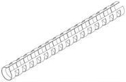
The guide catheter is composed as shown in fig. 1, and the guide catheter 100 includes a catheter main body 110 extending axially, a diffusive stress tube 120 and a connector 130, and both ends of the diffusive stress tube 120 are connected to the catheter main body 110 and the connector 130, respectively.
Wherein the catheter body 110 is generally a multi-layer composite tube, as shown in fig. 2, the catheter body 110 comprises an inner tube 111, an outer tube 113, and an intermediate layer 112 between the inner tube 111 and the outer tube 113, the intermediate layer 112 being configured to have a relatively greater stiffness; the intermediate layer 112 is provided with an axially extending opening 300, and the inner tubular body 111 is configured with a circumferentially extensible inactive zone of extensibility 200, the inactive zone of extensibility 200 being at least partially received within the opening of the intermediate layer 112.
The section of the catheter main body 110 is as shown in fig. 3A, and the guide catheter of the present embodiment is provided with the non-actively extending region 200 so that the outer diameter thereof is smaller than that of the other guide catheter having a non-expandable inner diameter, and when the same-size instrument is delivered, the instrument can reach a predetermined position through a tortuous blood vessel more easily in the process of puncturing and subsequent positioning, and the delivery resistance is smaller, so that the injury to the lumen of the blood vessel is smaller. In addition, after the guide catheter is in place, the guide catheter can ensure strong support and provide larger space for the delivery of other instruments through self expansion, so that the delivery resistance of other instruments is reduced. The non-active extension region 200 is accommodated in the opening 300 of the middle layer, so that the space can be saved.
In some embodiments, the non-actively extensible region 200 comprises at least one relatively deployable laminate structure, as shown in figure 3A. The laminate structure may be a double-layer, triple-layer, quadruple-layer or more-layer laminate structure, and the structure of the non-active extension region 200 may be determined according to the thickness of the guiding catheter, the thickness of the inner-layer tube body and the middle layer, and other factors. In the catheter main body 110 of the present embodiment, the inner layer tube 111 needs to be expanded by the expander before being molded, and has a fixed shape when not subjected to an expansion force.
In some embodiments, the layered structure extends in a radial direction, i.e. the layered structures are stacked on top of each other in a radial direction, and in some embodiments the layered structure extends in a circumferential direction, i.e. the layered structures are stacked on top of each other in a circumferential direction. After the guiding catheter is delivered to the target site, the laminate structure can be deployed by a dilator to dilate the catheter.
In some embodiments, the laminated structures are configured with at least two, such as three, four, five or more, and a plurality of laminated structures are uniformly arranged along the circumference of the inner-layer tube body, as shown in fig. 3B. The more the inner tube 111 is constructed with the stacked structures, the more the radial size of the guiding catheter 100 can be further reduced, the smaller the conveying resistance, and the more uniformly arranged stacked structures can make the pressure applied to the inner tube more uniform and dispersed, so that the non-active expansion area can be more easily expanded, and the inner tube 111 will not deform unexpectedly after being expanded.
In some embodiments, the stacked structure extends linearly in the axial direction, as shown in fig. 3C, and the process is relatively simple.
In some embodiments, the laminated structure extends spirally along the inner tube, as shown in fig. 3D, and the inner tube 111 does not have a very thin wall and a thick wall when expanded, i.e., it does not have eccentricity.
In some embodiments, the opening 300 of the intermediate layer 112 is configured to mate with the laminate structure, as shown in FIG. 3E. The matching means that the number of the openings 300 of the middle layer 112 matches the number of the stacked structures, and the extending form of the openings 300 also matches the extending form of the stacked structures, so that each of the stacked structures can be respectively accommodated in the corresponding opening 300 of the middle layer 112. The radial dimension of the guiding catheter can be further reduced.
In some embodiments, at least one of the laminations is completely received within an opening in the intermediate layer 112 to reduce the radial dimension of the guide catheter, while the remaining laminations are configured to adhere tightly to the inner wall of the intermediate layer 112.
In some embodiments, the inner tube 111 includes an open body 1110, the inactive extension region 200 includes a first extension 210 and a third extension 230 on two sides, and at least one second extension 220 between the first extension 210 and the third extension 230, one end of each of the first extension 210 and the third extension 230 is fixedly connected to an end of the body 1110, and the other end of each of the first extension 210 and the third extension 230 is fixedly connected to an end of an adjacent second extension 220.
In the embodiment shown in fig. 3A, the inactive zone 200 has a second extension 220, that is, the inactive zone 200 has a three-layer laminated structure, the first extension 210, the second extension 220 and the third extension 230 are stacked in order radially outward, the first extension 210 has a first end 211 and a second end 212, the second extension 220 has a third end 221 and a fourth end 222, and the third extension 230 has a fifth end 231 and a sixth end 232: the first end 211 of the first extension 210 is fixedly connected to one end of the body 1110, the second end 212 of the first extension 210 is fixedly connected to the fourth end 222 of the second extension 220, the third end 221 of the second extension 220 is fixedly connected to the fifth end 231 of the third extension 230, and the sixth end 232 of the third extension 230 is fixedly connected to the other end of the body 1110.
The non-active extending area 200 is a continuous structure, the cross section of the inner tube 110 is a circumferential closed-loop structure, there is no opening, and the expanded inner tube is still a circumferential closed-loop structure. The space for expanding the lumen of the guiding catheter can be reserved by folding the inner tube 111 as shown in fig. 3A and 3B.
In some embodiments, when the inactive zone of extensibility 200 includes the first extension 210 and the third extension 230 on both sides, and the second extension 220 including two or more layers, the ends of adjacent second extensions 220 are fixedly connected, such that the inactive zone of extensibility 200 is configured as a continuous structure.
In some embodiments, the non-actively extending region 200 may also be configured as a discontinuous structure, that is, the inner tubular body 110 is configured as an open loop structure, which means that the wall of the inner tubular body 111 is axially broken (cut or cut), and the broken one side is overlapped on the other side to provide a space for expanding the lumen of the guiding catheter. The size compatibility is stronger, and the technology is relatively simple and easy to realize.
In the embodiment shown in fig. 4B, the inner tube 111 includes an open body 1110, the inactive zone 200 includes a first extension 210 and a third extension 230, one end of the first extension 210 and one end of the third extension 230 are fixedly connected to the end of the body 1110, and the first extension 210 at least partially overlaps the side of the third extension 230.
Specifically, the circumferential dimension of the first extending portion 210 matches the circumferential dimension of the third extending portion 230, and during molding, the first extending portion 210 and the third extending portion 230 are completely overlapped, so as to form a laminated structure. Of course, in some embodiments, the first extension 210 and the third extension 230 form a partially overlapping structure.
In some embodiments, the inactive zone 200 includes a first extension 210 and a third extension 230, and further includes a second extension disposed between the first extension 210 and the third extension 230, wherein one end of the second extension is fixedly connected to the first extension 210 or the third extension 230, and the other end of the second extension overlaps the lateral extensions, such that the inactive zone 200 is configured as a discontinuous structure. Of course, in some embodiments, the inactive zones of extensibility 200 may also be configured with two or more layers of second extensions 220, such that the inactive zones of extensibility 200 are configured as a multi-layer, non-continuous structure.
In this embodiment, the intermediate layer 112 is constructed as a mesh tube structure having a plurality of meshes, wherein the mesh tube structure is configured with the openings 300; the cross-sectional view is shown in fig. 5A, and the three-dimensional view is shown in fig. 5B, and the woven mesh tube is not completely closed when viewed in cross section, but a certain space is reserved for placing the non-active expansion region 200, so that when the inner diameter of the inner tube 111 expands, the middle layer 112 also expands along with the inner tube 111.
In a preferred embodiment, the intermediate layer 112 is formed by weaving wires into the mesh tube structure, and then is cut axially to form the opening 300. Specifically, the intermediate layer 112 is manufactured by weaving a thread to complete the closed-loop mesh tube structure, and then a laser cutting or mechanical cutting is used to cut a cut on the tube body of the woven mesh tube structure along the axial direction, so as to form the mesh tube structure with the opening 300. The intermediate layer 112 is made of a woven fabric, which is more flexible.
In some embodiments, the middle layer 112 is formed by cutting a tube to form a plurality of meshes. Specifically, the opening 300 and the holes are cut axially from the complete metal tube to form the intermediate layer 112 shown in fig. 5C in a cross-sectional view and fig. 5D in a three-dimensional view. The cut and formed interlayer is also reserved with an opening 300 for placing the non-active extension area 200, and the surface of the interlayer 112 is processed to remove redundant materials, so that the rigidity of the net pipe structure can be improved, the overall flexibility of the catheter main body 110 is improved, and the mesh of the cut and formed interlayer 112 is not limited.
In this embodiment, the guide catheter further includes a visualization portion 114 located at the distal end of the intermediate layer 112. To ensure good development of the developing part 114, the thickness of the developing part 114 should not be less than 0.0015 inch.
Further, in order to reduce the resistance of the visualization portion 114 to the expansion of the inner tube 111 and ensure that the lumen of the guiding catheter is well opened, in some embodiments, the visualization portion 114 is configured to have at least one second opening 310 extending in the axial direction, and the non-active expansion area 200 is configured to be received in the second opening 310. The developing part 114 is configured to be a non-closed structure extending along the non-active extending area 200, and the developing part 114 of the non-closed structure enables the tip of the guiding catheter to be expanded, so that friction between the inner surface of the lumen of the guiding catheter and the outer surface of the intermediate catheter can be reduced, damage to the hydrophilic coating on the outer surface of the intermediate catheter can be reduced, and the risk of the hydrophilic coating falling off can be reduced.
In some embodiments, the developing part 114 includes a plurality of developing segments 1140, and the plurality of developing segments 1140 are arranged along the circumferential direction, and adjacent developing segments 1140 are arranged at intervals, so as to form a multi-segment structure. The multi-section design of the visualization portion 114 significantly reduces the resistance encountered by the catheter body 110 during distal-most expansion. In addition, the plurality of developing segments 1140 form a plurality of second openings, and when the non-active extension region 200 includes a plurality of stacked structures, the plurality of developing segments 1140 may be disposed according to the number of the stacked structures, so that each stacked structure can be accommodated in one second opening 310, thereby reducing the expansion resistance.
In the non-limiting embodiment shown in FIG. 6, the developer portion 114 is comprised of four developer segments 1140 having the same wall thickness, inner and outer diameters, and width. When the developing part 114 is assembled at the distal end of the catheter main body 110, the developing part 114 spatially replaces the position of the intermediate layer 112, that is, the inner layer tube 111, the developing part 114 and the outer layer tube 113 are sequentially arranged at the distal end of the catheter main body 110 from inside to outside, and the non-active extension region 200 is accommodated in the second opening 310 between the two developing segments 1140, as shown in fig. 7.
In some embodiments, the development portion 114 may be configured to have a development segment that is an open loop structure having a second opening to accommodate the inactive extension region 200. Wherein, the number of the developing segments can be set according to actual needs.
In a preferred embodiment, the guide catheter 100 is configured to return to its original shape after delivery of the instrument is completed. For example, the inner tube 111 and the outer tube 113 are made of elastic material, for example, the inner tube 111 is made of teflon, and the intermediate layer 112 is made of shape memory material, such as nitinol. After the guiding catheter is expanded and the instrument is delivered to the position, the middle layer 112 is controlled to restore the original shape, and the inner layer tube 111 and the outer layer tube 113 shrink, so that the guiding catheter is convenient to withdraw.
Specifically, the elastic material of the outer tube 113 has a plurality of hardness gradients, the hardness decreases from the proximal end to the distal end in sequence, the proximal end has a high hardness, the pushing is good, the distal end has a low hardness, and the flexibility is good.
As shown in fig. 1-3 and 7, the guide catheter is a multi-layered single lumen tube containing multiple materials and has a circular cross-sectional shape. The inner tubular member 111 is typically made of Polytetrafluoroethylene (PTFE) or other polymeric material having a low coefficient of friction, and may be formed by an extrusion process. The intermediate layer 112 is made of stainless steel or other biocompatible materials without shape memory, can be prepared by processes such as tubular laser cutting, silk thread weaving and the like, and improves the rigidity of the intermediate layer 112 through a heat treatment process, so that the overall flexibility of the catheter is changed. The intermediate layer 112 can provide better mechanical property, flexibility, bending resistance and pressure resistance for the guide tube, and can realize whole body development (developing material), and the inner layer tube body 111 and the outer layer tube body 113 cannot realize whole body development.
The outer tube 113 is generally made of Thermoplastic Polyurethane (TPU), block polyether amide resin (Pebax), High Density Polyethylene (HDPE), Nylon (Nylon) and other high polymer materials with good elasticity, and can be made into a tube raw material by an extrusion method, and the stiffness of the catheter is transited by a splicing process. A hydrophilic coating such as polyvinylpyrrolidone (PVP) is typically added to the outside of the outer tubular body 113 to reduce friction between the tubular body and the inner wall of the blood vessel during delivery of the catheter to the blood vessel of the human body and to reduce damage to the blood vessel of the human body during use of the catheter. The outer tubular body 113 is a closed single lumen tube, and is nested over the inner tubular body 111 and the intermediate layer 112 by a process such as coating.
The developing part 114 is generally made of a metal developing alloy material such as platinum iridium, platinum tungsten, platinum nickel, etc., or a polymer material containing barium sulfate, and the developing part shows a shadow under X-ray to mark the position of the distal end of the catheter. By adjusting the wall thickness of the tube material of the inner tube 111 and the outer tube 113, the wire diameter, the weave pattern and the weave lattice density of the intermediate layer 112 can be adjusted to adjust the flexibility of the catheter body 110. The length of the catheter body 110 may be adjusted depending on the conditions and circumstances of use. Typically, the intermediate layer 112 is a woven mesh tube made of 16-32 woven filaments or a cut metal tube.
The guiding catheter described in this embodiment is an expandable guiding catheter, wherein the structures of the inner tube 111, the intermediate layer 112 and the developing part 114 are key to realize the expansion of the catheter lumen. The expansion of the inner lumen of the expandable guiding catheter needs to be achieved by means of external forces, i.e. by means of a dilator 400, the dilator 400 being shown in fig. 8, the dilator 400 having a distal second tip 401, and a straight section 402 between the second tip 401 and the second proximal end 403.
The guiding catheter of the embodiment is provided with two dilators in use, when the expandable guiding catheter is used for puncture, the inner cavity does not need to be dilated, and the puncture is carried out by using the first dilator with the outer diameter matched with the size of the inner cavity of the catheter. When the expandable guiding catheter reaches a desired location, the lumen of the guiding catheter needs to be expanded to deliver the device, a second dilator, which is thicker than the first dilator, is used.
The guiding catheter lumen of this embodiment has a first inner diameter when unexpanded and a second inner diameter when the non-actively dilated region 200 is fully dilated. The outer diameter of the straight section 402 of the second dilator is larger than the first inner diameter of the guiding catheter, theoretically smaller than the second inner diameter, and the outer diameter of the tip 401 is smaller than the first inner diameter, so that the second dilator can smoothly enter the lumen of the guiding catheter.
As the straight section 402 of the second dilator enters the lumen of the guiding catheter, the lumen of the guiding catheter is expanded, the laminated part of the non-active expanding area 200 of the inner layer tube 111 is continuously reduced, the middle layer 112 and the developing part 114 extend to the circumferential direction along with the expansion of the inner layer tube 111, and the outer layer tube 113 is also expanded along the circumferential direction due to the elasticity of the outer layer tube 113; when the straight section 402 of the second dilator is partially passed through the distal-most end of the guiding catheter, the intraluminal expansion will be achieved as a whole.
While the foregoing is directed to the preferred embodiment of the present invention, it is not intended to detail all of the same, and it is to be understood that such embodiment is merely illustrative of the present invention and is not to be considered as limiting the scope of the invention, which is limited only by the claims and their full scope and equivalents.
The embodiments were chosen and described in order to best explain the principles of the invention and the practical application, to thereby enable others skilled in the art to best utilize the invention. In practice, the invention will be understood to cover all modifications and variations of this invention provided they come within the scope of the appended claims. The technical features in the different embodiments above may be combined arbitrarily without conflict.