CN113200443B - A U-shaped steel bar hanger - Google Patents
A U-shaped steel bar hanger Download PDFInfo
- Publication number
- CN113200443B CN113200443B CN202110575685.2A CN202110575685A CN113200443B CN 113200443 B CN113200443 B CN 113200443B CN 202110575685 A CN202110575685 A CN 202110575685A CN 113200443 B CN113200443 B CN 113200443B
- Authority
- CN
- China
- Prior art keywords
- shaped steel
- lifting
- main
- steel bar
- fixed
- Prior art date
- Legal status (The legal status is an assumption and is not a legal conclusion. Google has not performed a legal analysis and makes no representation as to the accuracy of the status listed.)
- Active
Links
- 229910000831 Steel Inorganic materials 0.000 title claims abstract description 88
- 239000010959 steel Substances 0.000 title claims abstract description 88
- 210000003205 muscle Anatomy 0.000 claims 1
- 239000000725 suspension Substances 0.000 description 19
- 238000000034 method Methods 0.000 description 14
- 230000008569 process Effects 0.000 description 12
- 230000000903 blocking effect Effects 0.000 description 5
- 238000003466 welding Methods 0.000 description 5
- XEEYBQQBJWHFJM-UHFFFAOYSA-N Iron Chemical group [Fe] XEEYBQQBJWHFJM-UHFFFAOYSA-N 0.000 description 4
- 238000010586 diagram Methods 0.000 description 3
- 238000010276 construction Methods 0.000 description 2
- 230000006872 improvement Effects 0.000 description 2
- 210000001015 abdomen Anatomy 0.000 description 1
- 230000009471 action Effects 0.000 description 1
- 230000008859 change Effects 0.000 description 1
- 230000007547 defect Effects 0.000 description 1
- 210000005069 ears Anatomy 0.000 description 1
- 230000000694 effects Effects 0.000 description 1
- 230000005484 gravity Effects 0.000 description 1
- 238000009434 installation Methods 0.000 description 1
- 238000004519 manufacturing process Methods 0.000 description 1
- 238000012986 modification Methods 0.000 description 1
- 230000004048 modification Effects 0.000 description 1
- 239000011150 reinforced concrete Substances 0.000 description 1
Images


Classifications
-
- B—PERFORMING OPERATIONS; TRANSPORTING
- B66—HOISTING; LIFTING; HAULING
- B66C—CRANES; LOAD-ENGAGING ELEMENTS OR DEVICES FOR CRANES, CAPSTANS, WINCHES, OR TACKLES
- B66C1/00—Load-engaging elements or devices attached to lifting or lowering gear of cranes or adapted for connection therewith for transmitting lifting forces to articles or groups of articles
- B66C1/10—Load-engaging elements or devices attached to lifting or lowering gear of cranes or adapted for connection therewith for transmitting lifting forces to articles or groups of articles by mechanical means
- B66C1/12—Slings comprising chains, wires, ropes, or bands; Nets
- B66C1/14—Slings with hooks
-
- B—PERFORMING OPERATIONS; TRANSPORTING
- B66—HOISTING; LIFTING; HAULING
- B66C—CRANES; LOAD-ENGAGING ELEMENTS OR DEVICES FOR CRANES, CAPSTANS, WINCHES, OR TACKLES
- B66C13/00—Other constructional features or details
- B66C13/04—Auxiliary devices for controlling movements of suspended loads, or preventing cable slack
- B66C13/06—Auxiliary devices for controlling movements of suspended loads, or preventing cable slack for minimising or preventing longitudinal or transverse swinging of loads
-
- B—PERFORMING OPERATIONS; TRANSPORTING
- B66—HOISTING; LIFTING; HAULING
- B66C—CRANES; LOAD-ENGAGING ELEMENTS OR DEVICES FOR CRANES, CAPSTANS, WINCHES, OR TACKLES
- B66C13/00—Other constructional features or details
- B66C13/04—Auxiliary devices for controlling movements of suspended loads, or preventing cable slack
- B66C13/08—Auxiliary devices for controlling movements of suspended loads, or preventing cable slack for depositing loads in desired attitudes or positions
Landscapes
- Engineering & Computer Science (AREA)
- Mechanical Engineering (AREA)
- Load-Engaging Elements For Cranes (AREA)
Abstract
本发明属于载荷吊挂机械装置领域,并具体公开了一种U型钢筋吊具,其包括吊链、主吊梁和次吊梁,其中:两根所述吊链对称安装在所述主吊梁上,且两根吊链通过吊环相互连接,两根吊链和主吊梁之间呈等腰三角形;两根所述次吊梁分别对称固定在所述主吊梁两侧,且所述次吊梁底部安装有多个吊钩;所述吊链为柔性结构,所述主吊梁和次吊梁为刚性结构。本发明的U型钢筋吊具解决了目前U型钢筋吊运效率较低、人工成本高、U型钢筋变形大,以及稳定性和安全性差的问题。
The invention belongs to the field of load hoisting mechanical devices, and specifically discloses a U-shaped steel bar hanger, which comprises a hoisting chain, a main hoisting beam and a secondary hoisting beam, wherein: two of the hoisting chains are symmetrically installed on the main hoisting beam On the beam, and the two suspending chains are connected to each other through hoisting rings, the two suspending chains and the main suspending beam are in an isosceles triangle; the two secondary suspending beams are respectively fixed symmetrically on both sides of the main suspending beam, and the A plurality of hooks are installed at the bottom of the secondary suspending beam; the suspending chain is a flexible structure, and the main suspending beam and the secondary suspending beam are rigid structures. The U-shaped steel bar hanger of the present invention solves the problems of low lifting and transportation efficiency of the U-shaped steel bar, high labor cost, large deformation of the U-shaped steel bar, and poor stability and safety.
Description
技术领域technical field
本发明属于载荷吊挂机械装置领域,更具体地,涉及一种U型钢筋吊具。The invention belongs to the field of load hanging mechanical devices, and more particularly relates to a U-shaped steel bar hanger.
背景技术Background technique
在高速铁路桥梁建设中,U型钢筋是钢筋砼箱梁生产时用到的数量较多的一种特殊形状带肋钢筋,如图7所示。在箱梁钢筋骨架制作时,需要将U型钢筋运至钢筋骨架绑扎胎具中并实现其在胎具中的准确定位铺放。In the construction of high-speed railway bridges, U-shaped steel bar is a special-shaped ribbed steel bar used in the production of reinforced concrete box girder in large quantities, as shown in Figure 7. When the box girder steel skeleton is made, the U-shaped steel bars need to be transported to the steel skeleton binding mold and accurately positioned and laid in the tire mold.
目前的技术方案是:首先人工使用铁链或钢丝绳捆绑若干根堆放在一起的U型钢筋的两个部位,然后依靠龙门吊吊运至钢筋骨架绑扎胎具中,接着由人工解开捆绑的铁链或钢丝绳,并将钢筋一根一根地分拣出来,最后工人逐一将其搬运至预定设计位置。The current technical solution is as follows: first, manually use iron chains or steel wire ropes to bind two parts of several stacked U-shaped steel bars, and then rely on gantry cranes to hoist them to the steel frame binding tires, and then manually untie the bound iron chains Or steel wire ropes, and sort out the steel bars one by one, and finally the workers carry them to the predetermined design position one by one.
现有技术的主要不足之处是:现有技术方案需要工人频繁捆绑和拆除铁链或钢丝绳,并且还需要工人逐一控制好钢筋之间间距,进行准确地钢筋定位安装,花费时间较多,导致吊装效率较低和人工成本高;依靠柔性的铁链或钢丝绳进行吊装作业,可能造成U型钢筋的较大变形,影响工程质量;仅捆绑固定U型钢筋两个部位,吊运稳定性和安全性缺乏保障,吊装过程存在着一定的安全隐患。因此,亟需一种能提高吊装效率、保障吊运质量和安全的U型钢筋专用吊具。The main shortcomings of the prior art are: the prior art solution requires workers to frequently bind and remove iron chains or wire ropes, and also requires workers to control the spacing between the steel bars one by one, and perform accurate positioning and installation of the steel bars, which takes a lot of time, resulting in The hoisting efficiency is low and the labor cost is high; the hoisting operation relying on flexible iron chains or steel wire ropes may cause large deformation of the U-shaped steel bars and affect the quality of the project; only two parts of the U-shaped steel bars are bundled and fixed to ensure the stability and safety of hoisting and transportation. There is a lack of security, and there are certain safety hazards in the hoisting process. Therefore, there is an urgent need for a special sling for U-shaped steel bars that can improve hoisting efficiency and ensure hoisting quality and safety.
发明内容SUMMARY OF THE INVENTION
针对现有技术的以上缺陷或改进需求,本发明提供了一种U型钢筋吊具,其目的在于,提高U型钢筋的吊装效率,防止吊装过程中的U型钢筋变形,保障吊运质量和安全。In view of the above defects or improvement needs of the prior art, the present invention provides a U-shaped steel bar hanger, the purpose of which is to improve the hoisting efficiency of the U-shaped steel bar, prevent the deformation of the U-shaped steel bar during the hoisting process, and ensure the quality of hoisting and transportation. Safety.
为实现上述目的,本发明提出了一种U型钢筋吊具,包括吊链、主吊梁和次吊梁,其中:In order to achieve the above-mentioned purpose, the present invention proposes a U-shaped steel bar spreader, comprising a hanging chain, a main hanging beam and a secondary hanging beam, wherein:
两根所述吊链对称安装在所述主吊梁上,且两根吊链相互连接;两根所述次吊梁分别对称固定在所述主吊梁两侧,且所述次吊梁底部安装有多个吊钩;所述吊链为柔性结构,所述主吊梁和次吊梁为刚性结构。The two hanging chains are symmetrically installed on the main hanging beam, and the two hanging chains are connected to each other; the two secondary hanging beams are symmetrically fixed on both sides of the main hanging beam, and the bottom of the secondary hanging beam is A plurality of hoisting hooks are installed; the hoisting chain is a flexible structure, and the main hoisting beam and the secondary hoisting beam are rigid structures.
作为进一步优选的,所述次吊梁下端安装有定位挡杆,该定位挡杆下端开设有与所述吊钩对应的槽口。As a further preferred option, a positioning blocking rod is installed at the lower end of the secondary hanging beam, and a notch corresponding to the hanging hook is provided at the lower end of the positioning blocking rod.
作为进一步优选的,所述定位挡杆两端均设有拉伸弹簧,该拉伸弹簧一端固定在所述定位挡杆上,另一端固定在所述次吊梁的底部翼缘上。As a further preference, tension springs are provided at both ends of the positioning blocking rod, one end of the tension spring is fixed on the positioning blocking rod, and the other end is fixed on the bottom flange of the secondary suspension beam.
作为进一步优选的,所述定位挡杆下端开设的槽口为V形槽口。As a further preferred option, the notch provided at the lower end of the positioning blocking rod is a V-shaped notch.
作为进一步优选的,所述次吊梁底部安装有多行多列吊钩,同一列吊钩对应同一个槽口,所有吊钩的开口方向相同。As a further preference, there are multiple rows and columns of hooks installed at the bottom of the secondary lifting beam, the hooks in the same row correspond to the same notch, and the opening directions of all the hooks are the same.
作为进一步优选的,所述主吊梁为工字吊梁。As a further preference, the main suspension beam is an I-shaped suspension beam.
作为进一步优选的,所述主吊梁上端对称设置有两个吊耳,该吊耳用于连接所述吊链,两根所述吊链之间通过吊环连接。As a further preference, two lifting lugs are symmetrically arranged on the upper end of the main suspension beam, the suspension lugs are used to connect the suspension chains, and the two suspension chains are connected by a suspension ring.
作为进一步优选的,所述主吊梁和吊耳通过螺钉固定,且螺钉与主吊梁连接处设有方斜垫圈,该方斜垫圈斜面的斜度与主吊梁工字顶部下表面的斜度相等。As a further preference, the main hanging beam and the lifting lug are fixed by screws, and a square inclined washer is provided at the connection between the screw and the main hanging beam. degrees are equal.
作为进一步优选的,所述主吊梁和次吊梁通过螺钉固定,且螺钉与主吊梁连接处设有方斜垫圈,该方斜垫圈斜面的斜度与主吊梁工字底部上表面的斜度相等。As a further preference, the main hanging beam and the secondary hanging beam are fixed by screws, and a square inclined washer is provided at the connection between the screw and the main hanging beam. The slope is equal.
作为进一步优选的,所述吊钩上设置有螺纹。As a further preference, threads are provided on the hook.
总体而言,通过本发明所构思的以上技术方案与现有技术相比,主要具备以下的技术优点:In general, compared with the prior art, the above technical solutions conceived by the present invention mainly have the following technical advantages:
1.本发明中两根柔性吊链和刚性主吊梁之间形成一个等腰三角形,提高吊运过程的稳定性,同时采用刚性的主吊梁和次吊梁,可以避免吊链的两个下方吊点在重力作用下靠拢,避免U型钢筋在吊运过程中发生较大变形,提高工程质量,装置稳定性、安全性好、效率高,且结构简单、操作方便。1. An isosceles triangle is formed between the two flexible suspension chains and the rigid main suspension beam in the present invention to improve the stability of the hoisting process, and the rigid main suspension beam and the secondary suspension beam are adopted simultaneously to avoid two The lower lifting points are moved closer together under the action of gravity to avoid the large deformation of the U-shaped steel bars during the lifting and transportation process, improving the quality of the project.
2.本发明设有固定间距定位的带槽定位挡杆,以限制U型钢筋的移动并对U型钢筋进行定位,保证U型钢筋之间的距离保持为设计尺寸,减少吊运过程中的晃动和碰撞,能够一次性安装多根U型钢筋到钢筋骨架绑扎胎具上,提高了吊装效率;同时,将槽口设置为V形,相比常用的U形钢筋定位槽口,V形槽口进入难度小,且定位能力更强。2. The present invention is provided with a slotted positioning stopper positioned at a fixed distance to limit the movement of the U-shaped steel bars and to position the U-shaped steel bars, so as to ensure that the distance between the U-shaped steel bars is kept as the design size, and to reduce the hoisting process. Shaking and collision, it is possible to install multiple U-shaped steel bars to the steel frame binding tire at one time, which improves the hoisting efficiency; at the same time, the notch is set to V-shaped, compared with the commonly used U-shaped steel bar positioning notch, V-shaped groove The entrance is less difficult and the positioning ability is stronger.
3.本发明进一步设置了拉伸弹簧,在吊装过程中,通过拉伸弹簧的拉伸变形改变边长,并在吊装过程中提供作用力使带槽定位挡杆压紧U型钢筋,避免U型钢筋在吊装过程出现相对于吊具的大幅移动甚至脱离吊具钩挂的现象,导致吊运出现安全隐患。3. The present invention is further provided with a tension spring. During the hoisting process, the side length is changed by the tensile deformation of the tension spring, and during the hoisting process, a force is provided to make the slotted positioning stopper press the U-shaped steel bar to avoid U-shaped steel bars. During the hoisting process, the shaped steel bars may move significantly relative to the spreader or even break away from the hook of the spreader, resulting in potential safety hazards for hoisting.
4.本发明在次吊梁底部安装有多行吊钩,使U型钢筋末端由多个吊钩吊起,且吊钩上设置有螺纹,保证吊装稳定,同时配合带槽定位挡杆和拉伸弹簧对吊具U型钢筋进行多点固定和活动限制,使得吊装过程安全可靠。4. In the present invention, multiple rows of hooks are installed at the bottom of the secondary lifting beam, so that the ends of the U-shaped steel bars are lifted by multiple hooks, and the hooks are provided with threads to ensure stable hoisting, and at the same time cooperate with the slotted positioning bar and pull. The extension spring performs multi-point fixation and movement restriction on the U-shaped steel bar of the spreader, which makes the hoisting process safe and reliable.
5.本发明工字主吊梁上下两端通过螺钉分别与吊耳和次吊梁固定,在螺钉与主吊梁连接处设有合适斜度的方斜垫圈,防止工字主吊梁两端斜度对固定垂直度的影响。5. The upper and lower ends of the I-shaped main hanging beam of the present invention are respectively fixed with the lifting lugs and the secondary hanging beam by screws, and a square inclined washer with a suitable inclination is provided at the connection between the screw and the main hanging beam to prevent the two ends of the I-shaped main hanging beam. The effect of slope on fixed verticality.
附图说明Description of drawings
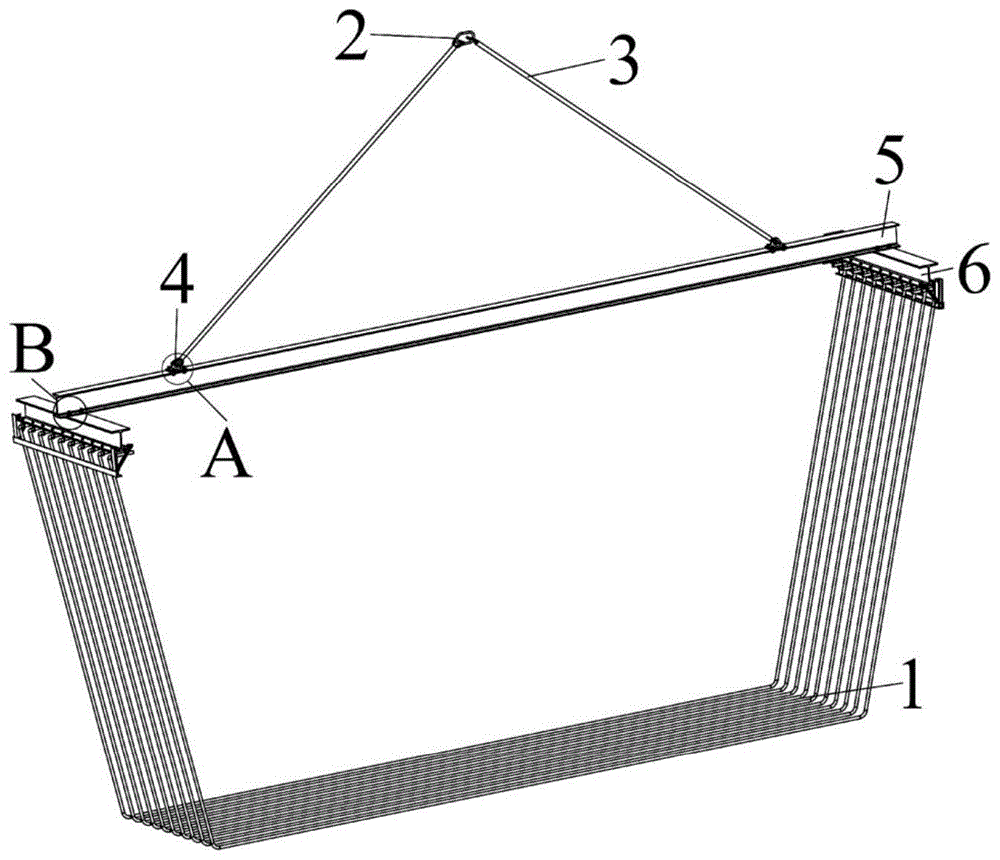
图1为本发明实施例U型钢筋吊具结构示意图;1 is a schematic structural diagram of a U-shaped steel bar spreader according to an embodiment of the present invention;
图2为图1中A处的结构放大图;Fig. 2 is an enlarged view of the structure at A place in Fig. 1;
图3为图1中B处的结构放大图;Figure 3 is an enlarged view of the structure at B in Figure 1;
图4为本发明实施例次吊梁装配体的结构示意图;4 is a schematic structural diagram of a secondary hanging beam assembly according to an embodiment of the present invention;
图5为本发明实施例次吊梁装配体的主视局部图;FIG. 5 is a partial front view of a secondary hanging beam assembly according to an embodiment of the present invention;
图6为本发明实施例次吊梁装配体的侧视剖面图;6 is a side cross-sectional view of a secondary suspension beam assembly according to an embodiment of the present invention;
图7为U型钢筋结构示意图。Figure 7 is a schematic diagram of the U-shaped steel structure.
在所有附图中,相同的附图标记用来表示相同的元件或结构,其中:1-U型钢筋,2-椭圆吊环,3-吊链,4-吊耳,401-吊耳固定六角头螺栓,402-吊耳固定六角螺母,403-吊耳固定工字钢用方斜垫圈,5-主吊梁,6-次吊梁,601-次吊梁固定六角头螺栓,602-次吊梁固定六角螺母,603-次吊梁固定工字钢用方斜垫圈,7-弹簧连接固定座,8-第一弹簧连接短杆,9-定位挡杆,10-吊钩,1001-吊钩固定上螺母,1002-上弹簧垫圈,1003-下弹簧垫圈,1004-吊钩固定下螺母,11-拉伸弹簧,1101-第一吊环螺钉,1102-第一吊环螺母,1103-第二吊环螺钉,1104-第二吊环螺母,12-第二弹簧连接短杆,13-短杆连接固定座,1301-销轴,1302-开口销。In all drawings, the same reference numerals are used to denote the same elements or structures, wherein: 1-U-shaped steel bar, 2-Oval lifting ring, 3-Lifting chain, 4-Lifting lug, 401-Lifting lug fixing hex head Bolts, 402-Hexagonal nuts for fixing lifting lugs, 403-Square inclined washers for fixing I-beams for lifting ears, 5-Main lifting beams, 6-Secondary lifting beams, 601-Secondary lifting beam fixing hexagon head bolts, 602-Secondary lifting beams Fixing hexagon nut, 603-Square inclined washer for fixing I-beam for secondary lifting beam, 7-Spring connection fixing seat, 8-First spring connection short rod, 9-Positioning stop rod, 10-Hook, 1001-Hook fixing Upper nut, 1002-upper spring washer, 1003-lower spring washer, 1004-hook fixing lower nut, 11-tension spring, 1101-first eyebolt, 1102-first eyenut, 1103-second eyebolt, 1104-Second lifting ring nut, 12-Second spring connecting short rod, 13-Short rod connecting fixed seat, 1301-Pin shaft, 1302-Split pin.
具体实施方式Detailed ways
为了使本发明的目的、技术方案及优点更加清楚明白,以下结合附图及实施例,对本发明进行进一步详细说明。应当理解,此处所描述的具体实施例仅仅用以解释本发明,并不用于限定本发明。此外,下面所描述的本发明各个实施方式中所涉及到的技术特征只要彼此之间未构成冲突就可以相互组合。In order to make the objectives, technical solutions and advantages of the present invention clearer, the present invention will be further described in detail below with reference to the accompanying drawings and embodiments. It should be understood that the specific embodiments described herein are only used to explain the present invention, but not to limit the present invention. In addition, the technical features involved in the various embodiments of the present invention described below can be combined with each other as long as they do not conflict with each other.
本发明实施例提供的一种U型钢筋吊具,如图1所示,包括两根吊链3、工字型的主吊梁5和两根H型钢的次吊梁6,其中:A U-shaped steel bar hanger provided by the embodiment of the present invention, as shown in FIG. 1, includes two hanging
所述主吊梁5上侧靠近两端处对称连接有两个吊耳4,两根所述吊链3的一端分别安装在一个吊耳4上,两根吊链3另一端通过椭圆吊环2相互连接,使两根吊链3和主吊梁5之间呈等腰三角形;两根所述次吊梁6分别固定在所述主吊梁5两端附近,且所述次吊梁6底部安装有多个吊钩10,该吊钩10用于钩挂U型钢筋1。The upper side of the main hanging
进一步的,如图5所示,弹簧连接固定座7通过焊接固定在次吊梁6底部两端翼缘前侧,拉伸弹簧11固定端通过第一吊环螺钉1101和第一吊环螺母1102连接并固定在弹簧连接固定座7上;如图6所示,短杆连接固定座13通过焊接固定在次吊梁6底部两端翼缘后侧,第一弹簧连接短杆8(第二弹簧连接短杆12和其结构相同)的固定端通过销轴1301和开口销1302连接并固定在短杆连接固定座13上;拉伸弹簧11活动端通过第二吊环螺钉1103和第二吊环螺母1104连接并固定在第一弹簧连接短杆8(第二弹簧连接短杆12和其结构相同)的活动端上;定位挡杆9的两端通过焊接将第一弹簧连接短杆8和第二弹簧连接短杆12的活动端固定成为一个整体,定位挡杆9下端设有一排与吊钩对应的V形的槽口,以在吊装时限制U型钢筋1的移动并对U型钢筋1进行定位,保证U型钢筋之间的距离保持为设计尺寸,方便工人一次性将全部U型钢筋1铺设进入钢筋骨架绑扎胎具中预定的凹槽中。第一弹簧连接短杆8、拉伸弹簧11和次吊梁6的底部翼缘形成边长可变的一个三角形,在吊装过程中,通过拉伸弹簧11的拉伸变形改变边长,并在吊装过程中提供作用力使第一弹簧连接短杆8、第二弹簧连接短杆12和带槽的定位挡杆9组成的整体压紧U型钢筋1,避免U型钢筋1在吊装过程出现相对于吊具的大幅移动甚至脱离吊具钩挂的现象,导致吊运出现安全隐患。Further, as shown in FIG. 5 , the spring
进一步的,如图4所示,次吊梁6底部翼缘位置设有多行多列吊钩10,吊钩10上设置有螺纹,吊钩10为圆弧状开口结构,其开口朝向同一个方向,以便在在吊装U型钢筋1时,能够同时钩挂起和放下U型钢筋1,减少工人一根根将U型钢筋1钩挂上吊具和从吊具取下U型钢筋1的时间,提高吊装的整体效率。Further, as shown in FIG. 4 , the position of the bottom flange of the
具体的,所述吊钩10通过依次设置的螺母和弹簧垫圈固定在所述次吊梁6底部。如图5所示,吊钩10固定在次吊梁6底部翼缘位置,且上下两侧分别通过上螺母1001、上弹簧垫圈1002,以及下弹簧垫圈1003、下螺母1004进行固定,上弹簧垫圈1002和下弹簧垫圈1003起到螺纹放松的作用,通过调整上螺母1001和下螺母1004可以调整螺纹吊钩10的开口朝向。Specifically, the hanging
进一步的,如图2所示,焊接吊耳4底板部位通过吊耳固定六角头螺栓401、吊耳固定六角螺母402和吊耳固定工字钢用方斜垫圈403与工字主吊梁接近端部腿端位置紧固连接,吊耳固定工字钢用方斜垫圈403斜面的斜度和工字主吊梁顶部腿端位置下面的斜度相等,来解决工字主吊梁顶部腿端位置下面与吊耳固定六角头螺栓401轴线不垂直的问题。如图3所示,工字主吊梁的两端底部腿端位置通过次吊梁固定六角头螺栓601、次吊梁固定六角螺母602和次吊梁固定工字钢用方斜垫圈603与次吊梁6中间顶部翼缘位置紧固连接,次吊梁固定工字钢用方斜垫圈603斜面的斜度和工字主吊梁底部腿端位置上表面的斜度相等,用来解决工字主吊梁底部腿端位置上表面与次吊梁固定六角头螺栓601轴线不垂直的问题。Further, as shown in FIG. 2 , the bottom plate part of the
采用上述U型钢筋吊具对U型钢筋进行吊装,该吊具及吊装方法适用于各种U型钢筋吊装,特别适合于高铁建设等场合。具体的,在吊装之前,需要在钢筋加工场制作好U型钢筋1,并将U型钢筋1运到钢筋骨架绑扎胎具附近,以便龙门吊和吊具的吊运作业,然后进行以下步骤:The U-shaped steel bar is hoisted by the above-mentioned U-shaped steel bar sling. The sling and the hoisting method are suitable for hoisting various U-shaped steel bars, especially for high-speed rail construction and other occasions. Specifically, before hoisting, the
S1、将在钢筋加工场制作好的U型钢筋1运到钢筋骨架绑扎胎具端部位置,按照预定距离有顺序的竖直姿态放置,以便后续操作;S1. Transport the
S2、将起重设备自带的吊钩与U型钢筋吊具中部的椭圆吊环2进行连接,操作起重设备向上移动,拉紧连接椭圆吊环2和吊耳4的吊链3,直至吊链3从松弛状态变为紧绷状态,等待吊具姿态稳定;S2. Connect the hook that comes with the lifting equipment to the
S3、工人绕销轴13位置向上转动第一弹簧连接短杆8、第二弹簧连接短杆12和定位挡杆9组成的整体,当拉伸弹簧11达到最大拉伸长度的临界位置时,继续向上转动焊接整体,依靠拉伸弹簧11的拉力,使第一弹簧连接短杆8、第二弹簧连接短杆12和定位挡杆9组成的整体稳定靠在次吊梁6的顶部翼缘位置,暴露出吊钩10的周边空间;S3. The worker rotates the first spring connecting
S4、工人通过操作起重设备移动,使得U型钢筋专用吊具两端的次吊梁6底部翼缘位置固定连接的多行多列吊钩10能够顺利同时钩挂起若干根U型钢筋1的两端;S4. The worker moves by operating the lifting equipment, so that the multi-row and multi-column hooks 10 fixedly connected at the bottom flange positions of the
S5、工人绕销轴1301位置向下转动第一弹簧连接短杆8、第二弹簧连接短杆12和定位挡杆9组成的整体,当拉伸弹簧11达到最大拉伸长度的临界位置时,继续向下转动焊接整体,依靠拉伸弹簧11的拉力,使第一弹簧连接短杆8、第二弹簧连接短杆12和定位挡杆9组成的整体稳定靠在U型钢筋1上,定位挡杆9的定位槽卡在U型钢筋1腹部位置,从而限制U型钢筋1的水平方向的晃动,避免U型钢筋1脱钩砸伤工人提高吊运的稳定性和安全性;S5. The worker rotates the first spring connecting
S6、通过起重设备移动U型钢筋专用吊具,如图1所示,将U型钢筋1以稳定的姿态吊装上升,并运至钢筋骨架绑扎胎具预定位置上方;S6. Move the special sling for U-shaped steel bar by lifting equipment, as shown in Figure 1, lift the
S7、操作起重设备,向下缓缓移动U型钢筋专用吊具,使得所有的U型钢筋1都准确卡进预先设置好的钢筋骨架绑扎胎具设置的凹槽中;S7. Operate the lifting equipment and slowly move the special sling for U-shaped steel bars downward, so that all the
S8、通过起重设备向下小幅度移动U型钢筋专用吊具,卸除吊钩10的载荷,使得次吊梁6底部翼缘位置的全部吊钩10与U型钢筋1端部位置脱离,再水平小幅度移动U型钢筋专用吊具,避开吊钩10和U型钢筋1端部在竖直方向的重叠,随后继续操作起重设备,向上移动U型钢筋专用吊具等待下一次吊运。S8. Move the special sling for U-shaped steel bar downward in a small amount through the lifting equipment to remove the load of the
S9、重复步骤S1~S8,直至将所有U型钢筋1吊装完毕。S9. Repeat steps S1 to S8 until all
本领域的技术人员容易理解,以上所述仅为本发明的较佳实施例而已,并不用以限制本发明,凡在本发明的精神和原则之内所作的任何修改、等同替换和改进等,均应包含在本发明的保护范围之内。Those skilled in the art can easily understand that the above are only preferred embodiments of the present invention, and are not intended to limit the present invention. Any modifications, equivalent replacements and improvements made within the spirit and principles of the present invention, etc., All should be included within the protection scope of the present invention.
Claims (8)
Priority Applications (1)
| Application Number | Priority Date | Filing Date | Title |
|---|---|---|---|
| CN202110575685.2A CN113200443B (en) | 2021-05-26 | 2021-05-26 | A U-shaped steel bar hanger |
Applications Claiming Priority (1)
| Application Number | Priority Date | Filing Date | Title |
|---|---|---|---|
| CN202110575685.2A CN113200443B (en) | 2021-05-26 | 2021-05-26 | A U-shaped steel bar hanger |
Publications (2)
| Publication Number | Publication Date |
|---|---|
| CN113200443A CN113200443A (en) | 2021-08-03 |
| CN113200443B true CN113200443B (en) | 2022-05-31 |
Family
ID=77023130
Family Applications (1)
| Application Number | Title | Priority Date | Filing Date |
|---|---|---|---|
| CN202110575685.2A Active CN113200443B (en) | 2021-05-26 | 2021-05-26 | A U-shaped steel bar hanger |
Country Status (1)
| Country | Link |
|---|---|
| CN (1) | CN113200443B (en) |
Families Citing this family (2)
| Publication number | Priority date | Publication date | Assignee | Title |
|---|---|---|---|---|
| CN113716445B (en) * | 2021-08-31 | 2022-05-31 | 华中科技大学 | U-shaped steel bar lifting appliance |
| CN114633243B (en) * | 2022-03-24 | 2023-07-07 | 中铁十二局集团有限公司 | U-shaped steel bar storage device and storage and hoisting method |
Family Cites Families (5)
| Publication number | Priority date | Publication date | Assignee | Title |
|---|---|---|---|---|
| CN203428727U (en) * | 2013-08-23 | 2014-02-12 | 上海铂实建筑工程有限公司 | Vertical lifting mechanism |
| CN203545443U (en) * | 2013-09-12 | 2014-04-16 | 漳平市万山竹业工贸有限公司 | Multiple-hook sling |
| CN205555858U (en) * | 2016-03-31 | 2016-09-07 | 亿昇(天津)科技有限公司 | Whole hoist system of lifting by crane of casing |
| CN211004200U (en) * | 2019-12-04 | 2020-07-14 | 河北辰力吊索具集团有限公司 | Multifunctional steel plate combined hoisting sling |
| CN213011542U (en) * | 2020-06-12 | 2021-04-20 | 中建科技武汉有限公司 | Multifunctional combined adjustable hanging frame |
-
2021
- 2021-05-26 CN CN202110575685.2A patent/CN113200443B/en active Active
Also Published As
| Publication number | Publication date |
|---|---|
| CN113200443A (en) | 2021-08-03 |
Similar Documents
| Publication | Publication Date | Title |
|---|---|---|
| CN113200443B (en) | A U-shaped steel bar hanger | |
| CN114229695B (en) | A method for hoisting special-shaped steel cage of underground continuous wall | |
| CN219906710U (en) | Adjustable lifting balance beam frame suitable for multiple machine stations | |
| CN210084716U (en) | General type steel reinforcement cage gallows | |
| CN101402436A (en) | Method and apparatus for disassembling cargo boom of climbing tower crane | |
| CN205296844U (en) | Precast box girder steel strand wires hoisting point | |
| CN208966124U (en) | A kind of novel clamp | |
| CN119142989A (en) | Be used for polygonal variable cross-section slope tower column reinforcing bar portion article integral hoisting hoist | |
| CN205442393U (en) | Posture that falls suspension system | |
| CN209308433U (en) | A multifunctional trolley for binding and installing cast-in-place beam reinforcement cages | |
| CN215828215U (en) | Self-balancing large-span net rack lifting structure | |
| CN212897610U (en) | Transverse connection fixing device for I-shaped steel | |
| CN210505201U (en) | Equipment for hoisting reinforcing steel bars in batches | |
| CN211257921U (en) | Steel bar truss building carrier plate draws device and system to one side | |
| CN210286440U (en) | A transport hoist for hoisting bridge girder erection machine | |
| CN210884909U (en) | Quick replacement vertical rolling mill rolling guide device | |
| CN114934441A (en) | Anti-slip temporary sling cable clamp structure | |
| CN103556574B (en) | The using method of fast hoisting steel girder member bar | |
| CN220684407U (en) | Lifting appliance device for installing prefabricated box girder | |
| CN220845067U (en) | Iron shoulder pole for tower crane hoisting template | |
| CN205906936U (en) | Glass curtain wall hoisting construction system | |
| CN219792145U (en) | Hanging bracket device for hoisting prefabricated T-beam | |
| CN219546456U (en) | Steel bar hoisting system | |
| CN216549204U (en) | Universal lifting appliance suitable for various prefabricated components | |
| CN204326658U (en) | LNG storage tank reinforced mesh wind-resistant column bracing means |
Legal Events
| Date | Code | Title | Description |
|---|---|---|---|
| PB01 | Publication | ||
| PB01 | Publication | ||
| SE01 | Entry into force of request for substantive examination | ||
| SE01 | Entry into force of request for substantive examination | ||
| GR01 | Patent grant | ||
| GR01 | Patent grant |