Clavicle middle section bone fracture plate
Technical Field
The invention relates to the technical field of medical instruments, in particular to a clavicle middle section bone fracture plate.
Background
The clavicle is S-shaped and is arranged between the sternum stem and the acromion. Is the only bony framework connecting the lower and upper limbs and the trunk. The clavicle is positioned under the skin and superficial, and is easy to fracture under the action of external force, the incidence rate of the clavicle fracture accounts for 2.6-5 percent of the total fracture, wherein the middle-segment fracture of the clavicle accounts for about 2/3 percent of the total fracture of the clavicle, and the clavicle fracture is mostly generated in children and young adults. Internal fixation therapy is one mode of clavicle fracture treatment, and among them, a nail plate system is one of the most commonly used internal fixation modes. The internal fixation treatment mode principle is to cut at the fracture broken end, place the bone fracture plate, make the bone fracture plate cross the fracture position, fix the bone fracture plate at the far and near both ends of the fracture with screws and make the skeleton at the fracture end obtain effective fixation. Therefore, the bone fracture plate has an appearance similar to the surface shape of the bone and is provided with screw holes for screws to pass through. At present, the locking bone fracture plates on the market have a plurality of or dozens of series products, the base shapes of the products are similar, and the sizes and the specifications of the products are different. Although the bone fracture plate reduces research and development and manufacturing costs and gives consideration to the basic anatomical structure of the clavicle, the bone fracture plate has a plurality of problems. In the past, the fracture block is spliced firstly, the fracture part is approximately anatomically reset as much as possible, and then the bone fracture plate is directly placed at the proper position of the fracture part. However, the general fracture is shortened and displaced, and the peripheral ligaments, muscles and tendons are pulled and are unstable, so that the fracture is difficult to reset.
Disclosure of Invention
The invention aims to provide a middle clavicle fracture plate to solve the problems in the background art. In order to achieve the purpose, the invention provides the following technical scheme: the utility model provides a clavicle middle section coaptation board, includes the coaptation board body, coaptation board body both ends are fusiformis structure, the top of fusiformis structure is convex, the centre of coaptation board body is the S-shaped structure, the coaptation board body divide into nearly chest clavicle joint section and nearly shoulder clavicle joint section, be equipped with nearly chest kirschner wire hole, nearly chest locking hole and sliding hole on nearly chest clavicle joint section, nearly chest kirschner wire hole is located the tip of nearly chest clavicle joint section, nearly chest locking hole is located between nearly chest kirschner wire hole and the sliding hole, be equipped with nearly shoulder locking hole on the nearly shoulder clavicle joint section, nearly shoulder locking hole is equipped with a plurality ofly, is equipped with nearly shoulder kirschner wire hole on the shoulder between the adjacent nearly shoulder locking hole, the tip of nearly shoulder clavicle joint section is equipped with nearly shoulder kirschner wire hole down.
Preferably, 4 through grooves are formed in the two ends of the bone fracture plate body, the through grooves are uniformly formed in the two sides of the bone fracture plate body, the through grooves are divided into a near chest through groove and a near shoulder through groove, the near chest through groove is located in the two sides of the two ends of the sliding hole, and the near shoulder through groove is located in the two sides of the Kirschner wire hole on the near shoulder.
Preferably, the back surface of the proximal shoulder clavicular joint section is provided with arc-shaped grooves, and the arc-shaped grooves are symmetrically positioned at two sides of the proximal shoulder clavicular joint section.
Preferably, the arc-shaped grooves are distributed between the near chest through groove and the near shoulder through groove and are positioned on two sides of the Kirschner wire hole on the near shoulder.
Preferably, the number of the near shoulder locking holes is 8, the number of the near shoulder kirschner wire holes is 7, the near shoulder locking holes and the near shoulder kirschner wire holes are distributed at equal intervals along a near shoulder clavicle joint section, and the near shoulder through grooves are positioned on two sides of the 2 near shoulder kirschner wire holes on the outermost side.
Preferably, the edge of the bone plate body is of a smooth curved surface structure.
Preferably, the proximal chest and shoulder locking holes are both full-thread single holes.
The invention has the technical effects and advantages that: the device is provided with the Kirschner wire holes which can be used for temporary fixation, the bone fracture plate can be accurately positioned on the bone surface by using the Kirschner wire holes at two ends, more Kirschner wire holes close to the two ends are used for soft tissue repair, more wires for small fracture blocks in the Kirschner wire holes at the middle part are used for bundling and fixing, meanwhile, the device can also be used for temporary fixation of forceps clamps of point type reduction forceps, and the Kirschner wire holes far away from the fracture ends are used for fixation, and the fracture displacement is finely adjusted by matching with the sliding holes, so that the anatomical reduction is realized, and the fracture recovery is facilitated; the sliding holes are formed in the segments close to the sternoclavicular joints, so that the fracture length is ensured, the fracture can be shortened generally after the fracture, the fracture can be reset by depending on the bone fracture plate under the condition that screws are fixed at two ends of the fracture, and the sliding holes are screwed down after the original anatomy of the clavicle is kept in cooperation with the fine adjustment of the Kirschner wire holes at the ends far away from the fracture. After the sliding hole is screwed down, when the locking hole is screwed down at the other end, the end where the sliding hole is located can be kept from tilting, and simultaneously, the tension-free locking of the locking screw at the outer side end of the sliding hole is facilitated; the front surface of the bone fracture plate body is not provided with the arc-shaped groove, the depth of the arc-shaped groove on the back surface is shallow, the curvature radius is large, the plasticity of fracture setting is improved, the stability and reliability of the whole structure of the bone fracture plate are ensured, the damage of blood circulation around the cortex lycii is reduced, and the fracture is easier to heal; all the locking holes are full-thread single holes, so that the contact area between the locking screws and the threads of the locking holes is increased, the angular stability of the bone fracture plate and the locking screw system is enhanced, adverse consequences such as secondary fracture, bone damage and the like caused by inexperience of a clinical operating doctor are avoided, and iatrogenic injuries are avoided.
Drawings
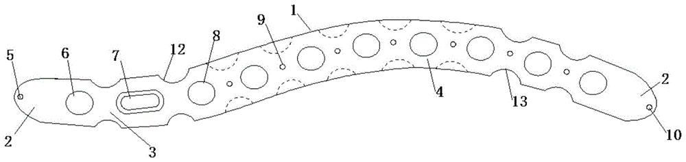
FIG. 1 is a front view of the present invention;
FIG. 2 is a rear view of the present invention;
FIG. 3 is a side view of the present invention;
fig. 4 is a schematic diagram of the operation of the present invention.
In the figure: the bone fracture plate comprises a bone fracture plate body, 2-a fusiform structure, 3-a chest-like clavicle joint section, 4-a shoulder-like clavicle joint section, 5-a chest-like Kirschner wire hole, 6-a chest-like locking hole, 7-a sliding hole, 8-a shoulder-like locking hole, 9-an upper shoulder Kirschner wire hole, 10-a lower shoulder Kirschner wire hole, 11-an arc groove, 12-a chest-like through groove and 13-a shoulder-like through groove.
Detailed Description
In the description of the present invention, it should be noted that unless otherwise specified or limited, the terms "mounted," "connected," and "connected" are to be construed broadly and may be, for example, fixedly connected, detachably connected, integrally connected, mechanically connected, or electrically connected; they may be connected directly or indirectly through intervening media, or they may be interconnected between two elements.
Example 1
The clavicle middle section bone fracture plate shown in fig. 1-3 comprises a bone fracture plate body 1, wherein two ends of the bone fracture plate body 1 are fusiform structures 2, the top end of each fusiform structure 2 is arc-shaped, so that the bone fracture plate can be inserted into the bone fracture plate, the operation of an operator is facilitated, soft tissue irritation is reduced, the middle of the bone fracture plate body 1 is of an S-shaped structure, the bone fracture plate body 1 is divided into a near-chest-clavicular joint section 3 and a near-shoulder-clavicular joint section 4, near-chest Kirschner wire holes 5, near-chest locking holes 6 and sliding holes 7 are formed in the near-chest-clavicular joint section 3, the near-chest Kirschner wire holes 5 are formed in the end portion of the near-chest-clavicular joint section 3, the near-chest locking holes 6 are formed between the near-chest Kirschner wire holes 5 and the sliding holes 7, near-shoulder-locking holes 8 are formed in the near-shoulder-clavicular joint section 4, a plurality of near-shoulder locking holes 8 are formed, near-shoulder-kirschner wires 9 are formed between adjacent near-shoulder-locking holes 8, the kirschner wire hole 9 on the near shoulder is mainly used for binding and fixing the silk thread of a small fracture block, and simultaneously can be used for temporarily fixing the forceps holder of a point-type reduction forceps, and simultaneously can be matched with the kirschner wire hole at the end far away from the fracture to be finely adjusted so as to achieve anatomical reduction and be beneficial to fracture recovery, the near shoulder lower kirschner wire hole 10 is arranged at the end part of the near shoulder joint locking section 4, and the near shoulder lower kirschner wire hole 10 and the near chest kirschner wire hole 5 are matched to accurately position the bone fracture plate on the bone surface.
Example 2
The clavicle middle section bone fracture plate shown in fig. 1-3 comprises a bone fracture plate body 1, wherein two ends of the bone fracture plate body 1 are fusiform structures 2, the top end of the fusiform structure 2 is arc-shaped, so that the bone fracture plate can be conveniently inserted, the operation of an operator is facilitated, soft tissue irritation is reduced, the edge of the bone fracture plate body 1 is of a smooth curved surface structure, the friction with the soft tissue is reduced, and postoperative discomfort is reduced, the middle of the bone fracture plate body 1 is of an S-shaped structure, the bone fracture plate body 1 is divided into a near-chest clavicular joint section 3 and a near-shoulder clavicular joint section 4, a near-chest kirschner wire hole 5, a near-chest locking hole 6 and a sliding hole 7 are arranged on the near-chest clavicular joint section 3, the near-chest kirschner wire hole 5 is arranged at the end part of the near-chest clavicular joint section 3, the near-chest locking hole 6 is arranged between the near-chest kirschner wire hole 5 and the sliding hole 7, and a near-shoulder locking hole 8 is arranged on the near-shoulder clavicular joint section 4, near shoulder Kirschner wire holes 9 are arranged between adjacent near shoulder locking holes 8, the near shoulder Kirschner wire holes 9 are mostly used for binding and fixing silk threads of small fracture blocks, can also be used for temporarily fixing forceps jaws of point type reduction forceps and can be matched with Kirschner wire holes far away from the fracture end for fine adjustment so as to achieve anatomical reduction and facilitate fracture recovery, near shoulder Kirschner wire holes 10 are arranged at the end parts of the near shoulder locking sections 4, the near shoulder Kirschner wire holes 10 and the near chest Kirschner wire holes 5 are matched so as to accurately position the near shoulder Kirschner wire holes on the bone surface, 4 through grooves are respectively formed at the two ends of the bone fracture plate body 1, the through grooves are uniformly formed at the two sides of the bone plate body 1 so as to facilitate the shaping of the two ends of the bone plate body 1 and make the bone plate more accord with the appearance of a clavicle, the through grooves are divided into near chest through grooves 12 and near shoulder through grooves 13, the near chest through grooves 12 are positioned at the two sides of the two ends of the sliding hole 7, the near shoulder through grooves 13 are positioned on two sides of a near shoulder Kirschner wire hole 10, the near shoulder locking holes 8 are 8, the near shoulder Kirschner wire holes 10 are 7, the near shoulder locking holes 8 and the near shoulder Kirschner wire holes 10 are distributed at equal intervals along a near shoulder locking segment 4, the near shoulder through grooves 13 are positioned on two sides of 2 near shoulder Kirschner wire holes 10 on the outermost side, the back of the near shoulder locking segment 4 is provided with arc-shaped grooves 11, the arc-shaped grooves 11 are symmetrically positioned on two sides of the near shoulder locking segment 4, the arc-shaped grooves 11 are distributed between a near chest through groove 12 and a near shoulder through groove 13 and are positioned on two sides of the near shoulder Kirschner wire holes 10, the depth is shallow, the curvature radius is larger, the plasticity of the fracture setting is improved, the stability and reliability of the whole structure of the bone fracture plate body 1 are ensured, the damage of the blood circulation around the cortical bone is reduced, the fracture of the chest is easier, the near shoulder locking holes 6 and the near shoulder locking holes 8 are full thread single holes, the contact area between the locking screw and the locking hole thread is increased, the angular stability of the bone fracture plate and the locking screw system is enhanced, meanwhile, adverse consequences of secondary fracture, bone damage and the like caused by inexperience of a clinical operating doctor are avoided, and iatrogenic injuries are avoided.
The process flow and the working principle of the invention are as follows: a specific fixing method of a clavicle middle section bone fracture plate is shown in figure 4, a proper bone fracture plate is selected according to the position of a clavicle middle section fracture line, the bone fracture plate is determined not to enter an acromioclavicular joint cavity through a Kirschner wire, 1.5 or 2.0mm Kirschner wire (single cortex) is driven into a Kirschner wire hole 10 near the shoulder of a acromioclavicular joint section 4, and whether the position of the near acromioclavicular joint section 4 is proper or not is confirmed through intraoperative C-arm machine perspective; if the bone fracture plate is suitable, a cortical bone screw is screwed into the near shoulder locking hole 8 on one side of the near shoulder kirschner wire hole 10 to fix double cortex, so that the near shoulder clavicular joint section 4 of the bone fracture plate body 1 is more attached to the bone surface, and then the kirschner wire in the near shoulder kirschner wire hole 10 is detached; the two reduction forceps are respectively used for approximately correcting the far and near end displacement (front and back, inside and outside and shortening) of the fracture end, and the approach dissection reduction is carried out; then a kirschner wire (single cortex can be used) with the diameter of 1.5 or 2.0mm is turned into a proximal kirschner wire hole 5 on the proximal sternoclavicular joint section 3, whether the position of the proximal sternoclavicular joint section 3 is positioned in the middle of the clavicle is confirmed through intraoperative C-arm machine perspective, and if the position is not positioned in the middle of the clavicle, the position of the proximal sternoclavicular joint section 3 is adjusted again through the kirschner wire until the position is satisfied; then a cortical bone screw is screwed in the sliding hole 7 on the proximal sternoclavicular joint section 3, the kirschner wire in the proximal sternoclavian wire hole 5 is removed, the shortening displacement is corrected, the cortical bone screw is screwed down while the displacement is corrected, and when the cortical bone screw is screwed down, the fracture is anatomically reset; common screws are respectively reserved at the far and near ends of the fracture, the Kirschner wires at the two ends are removed, the fracture end is unstable, the Kirschner wires can be driven into the Kirschner wire holes 9 in the middle of the bone fracture plate body 1 through the reduction forceps for temporary fixation, cortical screws are screwed into the near shoulder locking holes 8 in the middle of the bone fracture plate body 1 for double-cortical fixation, the reduction forceps or the Kirschner wires are temporarily fixed at the fracture end of the side in the same way, and the cortical screws are screwed into the near shoulder locking holes 8; after the relative stability and anatomical reduction of the fracture are confirmed (which can be confirmed by intraoperative fluoroscopy), the appropriate number of locking screws are screwed into the shoulder-proximal locking holes 8 and the chest-proximal locking holes 6 at the two ends of the fracture; finally, the cortical bone screw of the proximal shoulder locking hole 8 at the outermost side is replaced by a locking screw, the cortical bone screw in the sliding hole 7 is removed, the two cortical bone screws in the proximal shoulder locking hole 8 at the middle part are replaced by the locking screws, and the position and the length of the screws, the force line, the anatomical reduction of the fracture and the like are confirmed through perspective again.
Finally, it should be noted that: although the present invention has been described in detail with reference to the foregoing embodiments, it will be apparent to those skilled in the art that modifications may be made to the embodiments or portions thereof without departing from the spirit and scope of the invention.