CN113196009A - Sensing apparatus - Google Patents
Sensing apparatus Download PDFInfo
- Publication number
- CN113196009A CN113196009A CN201980083356.7A CN201980083356A CN113196009A CN 113196009 A CN113196009 A CN 113196009A CN 201980083356 A CN201980083356 A CN 201980083356A CN 113196009 A CN113196009 A CN 113196009A
- Authority
- CN
- China
- Prior art keywords
- capacitive surface
- resonant member
- capacitive
- surface portion
- electrode
- Prior art date
- Legal status (The legal status is an assumption and is not a legal conclusion. Google has not performed a legal analysis and makes no representation as to the accuracy of the status listed.)
- Granted
Links
Images


Classifications
-
- G—PHYSICS
- G01—MEASURING; TESTING
- G01C—MEASURING DISTANCES, LEVELS OR BEARINGS; SURVEYING; NAVIGATION; GYROSCOPIC INSTRUMENTS; PHOTOGRAMMETRY OR VIDEOGRAMMETRY
- G01C19/00—Gyroscopes; Turn-sensitive devices using vibrating masses; Turn-sensitive devices without moving masses; Measuring angular rate using gyroscopic effects
- G01C19/56—Turn-sensitive devices using vibrating masses, e.g. vibratory angular rate sensors based on Coriolis forces
- G01C19/5719—Turn-sensitive devices using vibrating masses, e.g. vibratory angular rate sensors based on Coriolis forces using planar vibrating masses driven in a translation vibration along an axis
- G01C19/5733—Structural details or topology
- G01C19/5755—Structural details or topology the devices having a single sensing mass
-
- G—PHYSICS
- G01—MEASURING; TESTING
- G01C—MEASURING DISTANCES, LEVELS OR BEARINGS; SURVEYING; NAVIGATION; GYROSCOPIC INSTRUMENTS; PHOTOGRAMMETRY OR VIDEOGRAMMETRY
- G01C19/00—Gyroscopes; Turn-sensitive devices using vibrating masses; Turn-sensitive devices without moving masses; Measuring angular rate using gyroscopic effects
- G01C19/56—Turn-sensitive devices using vibrating masses, e.g. vibratory angular rate sensors based on Coriolis forces
- G01C19/5705—Turn-sensitive devices using vibrating masses, e.g. vibratory angular rate sensors based on Coriolis forces using masses driven in reciprocating rotary motion about an axis
- G01C19/5712—Turn-sensitive devices using vibrating masses, e.g. vibratory angular rate sensors based on Coriolis forces using masses driven in reciprocating rotary motion about an axis the devices involving a micromechanical structure
-
- G—PHYSICS
- G01—MEASURING; TESTING
- G01P—MEASURING LINEAR OR ANGULAR SPEED, ACCELERATION, DECELERATION, OR SHOCK; INDICATING PRESENCE, ABSENCE, OR DIRECTION, OF MOVEMENT
- G01P1/00—Details of instruments
-
- G—PHYSICS
- G01—MEASURING; TESTING
- G01P—MEASURING LINEAR OR ANGULAR SPEED, ACCELERATION, DECELERATION, OR SHOCK; INDICATING PRESENCE, ABSENCE, OR DIRECTION, OF MOVEMENT
- G01P15/00—Measuring acceleration; Measuring deceleration; Measuring shock, i.e. sudden change of acceleration
- G01P15/02—Measuring acceleration; Measuring deceleration; Measuring shock, i.e. sudden change of acceleration by making use of inertia forces using solid seismic masses
- G01P15/08—Measuring acceleration; Measuring deceleration; Measuring shock, i.e. sudden change of acceleration by making use of inertia forces using solid seismic masses with conversion into electric or magnetic values
- G01P15/097—Measuring acceleration; Measuring deceleration; Measuring shock, i.e. sudden change of acceleration by making use of inertia forces using solid seismic masses with conversion into electric or magnetic values by vibratory elements
-
- G—PHYSICS
- G01—MEASURING; TESTING
- G01P—MEASURING LINEAR OR ANGULAR SPEED, ACCELERATION, DECELERATION, OR SHOCK; INDICATING PRESENCE, ABSENCE, OR DIRECTION, OF MOVEMENT
- G01P15/00—Measuring acceleration; Measuring deceleration; Measuring shock, i.e. sudden change of acceleration
- G01P15/02—Measuring acceleration; Measuring deceleration; Measuring shock, i.e. sudden change of acceleration by making use of inertia forces using solid seismic masses
- G01P15/08—Measuring acceleration; Measuring deceleration; Measuring shock, i.e. sudden change of acceleration by making use of inertia forces using solid seismic masses with conversion into electric or magnetic values
- G01P15/125—Measuring acceleration; Measuring deceleration; Measuring shock, i.e. sudden change of acceleration by making use of inertia forces using solid seismic masses with conversion into electric or magnetic values by capacitive pick-up
Landscapes
- Physics & Mathematics (AREA)
- General Physics & Mathematics (AREA)
- Engineering & Computer Science (AREA)
- Radar, Positioning & Navigation (AREA)
- Remote Sensing (AREA)
- Gyroscopes (AREA)
Abstract
一种感测设备,包括:能够在第一模式和第二模式下运动的谐振构件;以及电极。所述谐振构件具有电容性表面部分,所述电容性表面部分面对并且电容性地耦合到所述电极的电容性表面部分。在所述第一模式下沿所述谐振构件的电容性表面部分的每个点的位移与该点基本上相切。

A sensing device includes: a resonating member movable in a first mode and a second mode; and an electrode. The resonating member has a capacitive surface portion facing and capacitively coupled to the capacitive surface portion of the electrode. The displacement of each point along the capacitive surface portion of the resonating member in the first mode is substantially tangent to that point.
Description
Technical Field
The present application relates generally to sensing devices, and more particularly to sensing devices such as MEMS gyroscopes or MEMS accelerometers.
Background
Inertial measurement devices such as gyroscopes and accelerometers provide high precision sensing. Historically, however, their cost, size and power requirements have prevented their widespread use in industries such as consumer products, gaming devices, automotive and handheld positioning systems.
Recently, microelectromechanical system (MEMS) sensor devices have gained increased attention from a number of industries as microelectromechanical technology has made it possible to fabricate small gyroscopes and accelerometers. Miniaturization also enables integration of the MEMS device with the readout electronics on the same die, resulting in lower size, cost and power consumption and better resolution by reducing noise. Consumer products such as digital cameras, 3D gaming devices, and automotive sensors use MEMS devices for their many advantages. Consumer demand for low cost, more elaborate and user friendly devices has led to a dramatic rise in demand for MEMS sensors, which provide adequate reliability and performance at extremely low prices.
Prior art MEMS devices, such as those disclosed in U.S. patent nos. 7,543,496, 7,578,189, 7,892,876, 8,173,470, 8,372,67, 8,528,404 and 8,166,816, are capable of sensing rotational (i.e., angular velocity of rotation about an axis) or translational motion (i.e., linear acceleration along an axis) about and along an axis. These devices typically comprise a resonant member surrounded by a plurality of electrodes which are spaced from the resonant member by a capacitive spacing.
For example, the sensing device 110 shown in FIG. 12 corresponds to a MEMS gyroscope and includes a resonant member 112 and a plurality of electrodes 118 spaced from the resonant member 112. Each electrode 118 is capacitively coupled to the resonant member 112. More specifically, the resonant member 112 has a plurality of capacitive surface portions 122, each of the plurality of capacitive surface portions 122 facing and capacitively coupled to a capacitive surface portion 128 of the associated electrode 118. A capacitive channel 130 is thereby defined between the resonant member 112 and each electrode 118.
The resonant member 112 is capable of moving in two resonant modes, a drive mode and a sense mode. In particular, the two electrodes 118a, 118c are drive electrodes operable to apply a driving force to the resonant member 112 in the X-direction to excite the resonant member 112 and cause the resonant member 112 to vibrate at a given frequency (e.g., the natural frequency of the resonant member 112) in the drive mode. If the resonant member 112 rotates, the Coriolis effect transfers energy from the drive mode to the sense mode and causes the resonant member 112 to vibrate in the sense mode. Further, the two electrodes 118b, 118d are sensing electrodes configured to generate a current in response to a sensing mode motion of the resonant member 112 in a Y-direction perpendicular to the X-direction. This current can be analyzed to determine the rate of rotation of the resonant member 112.
Each electrode 118 is aligned with a node axis of the resonant member 112 (for purposes of this disclosure, a "node axis" of a resonant member is an axis passing through two or more nodes of the resonant member, and a "node" refers to one of the counter-nodes or nodes of the resonant member when it vibrates in either the drive mode or the sense mode). More specifically, the drive electrodes 118a, 118c and a first nodal axis N passing through two nodal points 134a, 134c of the resonant member 1121Aligned with, and passing through, the sensing electrodes 118b, 118d and the second nodal points N of the other two nodal points 134b, 134d of the resonant member 1122And (6) aligning. Two nodes 134a, 134c correspond to nodes of the resonant member 112 in the sensing mode and counter nodes of the resonant member 112 in the driving mode, while the other two nodes 134b, 134d correspond to counter nodes of the resonant member 112 in the sensing mode and nodes of the resonant member 112 in the driving mode. Furthermore, the capacitive surface portions 122, 128 of the resonant member 112 and the electrode 118 are preferably shaped and arranged such that their capacitive channels 130 are symmetrical about their associated node axes.
Ideally, the sensing mode will not be excited when the resonant member 112 is at zero velocity (i.e. no rotation), such that the sensing mode motion of the resonant member 112 in the Y direction is zero and no current output is generated at the sensing electrodes 118b, 118d which falsely indicates rotation. However, as discussed further below, some excitation of the sense electrodes 118b, 118d may occur even when the resonant member 112 is at zero velocity.
For example, the sensing device 110 in FIG. 12 is typically fabricated using a Deep Reactive Ion Etching (DRIE) process that separates the monomer material into the resonating member 112 and the electrode 118. A capacitive channel 130 is formed at the location of the etched monomer together with the resonant member 112 and the capacitive surface portions 122, 128 of the electrodes 118. As mentioned above, the capacitive surface portions 122, 128 of the resonant member 112 and the electrode 118 are preferably shaped and arranged such that their capacitive channels 130 are symmetrical about their associated nodal axes. However, due to imperfections in the DRIE process that occur when forming the ends of each channel 130, the capacitive surface portions 122, 128 may have imperfections at the ends of each channel 130 that cause the channel 130 to be asymmetric about its associated nodal axis.
FIG. 13 illustrates forming the capacitive channel 130b in the capacitive surface portion 128b of the sense electrode 118b about the second nodal axis N2Examples of asymmetric defects 142. When the drive electrodes 118a, 118c are operated in a drive mode to excite the resonant member 112, some drive mode motion will be experienced at the capacitive surface portion 122b of the resonant member 112 (see, for example, dashed line 146 in fig. 13 indicating drive mode motion of the resonant member 112). If the capacitive channel 130b for the sensing electrode 118b is about the second nodal axis N2Symmetrically, the total capacitive displacement of the capacitive surface portion 122b will be zero, thereby resulting in zero current at the sensing electrode 118 b. However, because the capacitive channel 130b is asymmetric, the total capacitive displacement of the capacitive surface portion 122b will be non-zero, thereby producing a zero velocity at the sensing electrode 118b that erroneously indicates rotation of the resonant member 112 and that may change with time and temperatureRate Output (ZRO).
Furthermore, if there is an asymmetry in one or both of the capacitive channels 130a, 130c for the drive electrodes 118a, 118c, this asymmetry may cause the drive electrodes 118a, 118c to also excite the resonant member 112 to move in a sensing mode at zero velocity, which may also produce a ZRO at the sense electrodes 118b, 118d (even if the capacitive channels 130b, 130d for the sense electrodes 118b, 118d are perfectly symmetric).
Reference list
Patent document
[ PTL 1] U.S. Pat. No.7,543,496
[ PTL 2] U.S. Pat. No.7,578,189
[ PTL 3] U.S. Pat. No.7,892,876
[ PTL 4] U.S. Pat. No.8,173,470
[ PTL 5] U.S. Pat. No.8,372,677
[ PTL 6] U.S. Pat. No.8,528,404
[ PTL 7] U.S. Pat. No.8,166,816
Disclosure of Invention
A simplified overview of an exemplary embodiment of the present invention is given below. The summary is not intended to identify key elements of the invention or to delineate the scope of the invention. The sole purpose of the summary is to present some example embodiments in a simplified form as a prelude to the more detailed description that is presented later.
According to a first aspect, a sensing device comprises: a resonant member movable in a first mode and a second mode; and an electrode. The resonance member has a capacitive surface portion facing and capacitively coupled to the capacitive surface portion of the electrode. The displacement of each point along the capacitive surface portion of the resonant member in the first mode is substantially tangential to that point.
In one example of the first aspect, the capacitive surface portion of the resonant member is curved.
In another example of the first aspect, the capacitive surface portion of the resonant member is concave.
In yet another example of the first aspect, the capacitive surface portion of the resonant member is convex.
In yet another example of the first aspect, the resonant member includes a body and a protrusion integrally connected to and protruding from the body, and the protrusion defines a capacitive surface portion of the resonant member. In one example, the protrusion extends from the body along a nodal axis of the resonant member, the protrusion includes a proximal portion and a distal portion, the distal portion being wider than the proximal portion, and the distal portion defining a capacitive surface portion of the resonant member. In one example, the proximal end portion of the protrusion is connected to a portion of the body that is displaced in a direction substantially parallel to the nodal axis in the second mode. In another example of the first aspect, the resonant member comprises a body, and the capacitive surface portion of the resonant member is a recessed surface portion of the body.
In yet another example of the first aspect, the sensing device includes a substrate; an anchor supporting the resonant member relative to the substrate; and a decoupling mechanism for flexibly decoupling the resonant member from the anchor. The decoupling mechanism includes: a flange connected to the anchor; a ring portion; a plurality of first elastic portions connecting the ring portion to the flange; and a plurality of second elastic parts connecting the loop part to the resonance member. Each of the first elastic portions has a rigidity lower than that of each of the second elastic members.
In yet another example of the first aspect, a gyroscope includes the sensing device.
According to a second aspect, a sensing device comprises: a resonant member movable in a first mode and a second mode; and an electrode. The electrode is arranged between the two capacitive surface portions of the resonance member such that one of the two capacitive surface portions of the resonance member faces and is capacitively coupled to the one capacitive surface portion of the electrode and the other of the two capacitive surface portions of the resonance member faces and is capacitively coupled to the other capacitive surface portion of the electrode. The displacement of each point along each of the two capacitive surface portions of the resonant member in the first mode is substantially tangential to that point.
In one example of the second aspect, the electrode and the resonant member define a capacitive channel between the electrode and the resonant member, and the two capacitive surface portions of the resonant member define two end portions of the capacitive channel, respectively.
In another example of the second aspect, the resonance member includes a main body and two protruding portions integrally connected to and protruding from the main body, and the electrode is disposed between the two protruding portions. One of the two protrusions defines one of the two capacitive surface portions of the resonant member and the other of the two protrusions defines the other of the two capacitive surface portions of the resonant member. In yet another example of the second aspect, the resonant member comprises a body, and each capacitive surface portion of the resonant member corresponds to a recessed surface portion of the body. In yet another example of the second aspect, the electrodes are disposed along a nodal axis of the resonant member.
According to a third aspect, a sensing device comprises: a resonant member movable in a first mode and a second mode, the resonant member comprising a main body and a protrusion extending from the main body along a nodal axis of the resonant member. The projection includes a proximal portion and a distal portion, the distal portion being wider than the proximal portion.
In one example of the third aspect, the sensing device comprises an electrode aligned with the protrusion along the nodal axis, wherein the proximal portion of the protrusion defines a capacitive surface portion of the resonant member that faces and is capacitively coupled to a capacitive surface portion of the electrode.
In another example of the third aspect, the proximal end portion of the protrusion is connected to a portion of the body that is displaced in a direction substantially parallel to the nodal axis in the second mode. In yet another example of the third aspect, the displacement of each point along the capacitive surface portion of the resonant member in the first mode is substantially tangential to that point. In one example, the capacitive surface portion of the resonant member is curved.
It is to be understood that both the foregoing general description and the following detailed description present exemplary and illustrative embodiments. The accompanying drawings are included to provide a further understanding of the described embodiments, and are incorporated in and constitute a part of this specification. The drawings illustrate different example embodiments.
Drawings
The foregoing and other aspects of the present invention will become apparent to those skilled in the art to which the present invention relates upon reading the following description in conjunction with the accompanying drawings, in which:
FIG. 1 is a schematic plan view of an example sensing device according to a first embodiment;
FIG. 2 is a schematic plan view of a sensing device according to a second embodiment;
FIG. 3 is a schematic plan view of a sensing device according to a third embodiment;
FIG. 4 is a schematic plan view of a sensing device according to a fourth embodiment;
FIG. 5 is an enlarged schematic plan view of a sensing device according to a fifth embodiment;
FIG. 6 is an enlarged schematic plan view of a sensing device according to a sixth embodiment;
FIG. 7 is an enlarged schematic plan view of a sensing device according to a seventh embodiment;
FIG. 8 is an enlarged schematic plan view of a sensing device according to an eighth embodiment;
FIG. 9 is a schematic plan view of an example decoupling mechanism of the sensing device;
FIG. 10 is a schematic partial perspective cross-sectional view of an anchor for a sensing device;
FIG. 11 is an enlarged schematic plan view of a sensing device forming a slit in an anchor;
FIG. 12 is a schematic plan view of an example sensing device in the prior art; and
fig. 13 is an enlarged view of the sensing device of fig. 12.
Detailed Description
Example embodiments shown in the drawings are described. The examples shown are not intended to limit the invention. For example, one or more aspects may be used in other embodiments and even other types of devices. Furthermore, specific terminology is used herein for convenience only and is not to be taken as a limitation.
Turning to fig. 1, a first embodiment of a sensing device 10 will now be described. The sensing device 10 in this example corresponds to a MEMS gyroscope. However, the sensing device 10 may correspond to other sensing devices such as a MEMS accelerometer in other examples.
The sensing device 10 in fig. 1 comprises a resonant member 12 supported relative to a substrate 16, and a plurality of electrodes 18 spaced from the resonant member 12. Each electrode 18 is capacitively coupled to the resonant member 12. More specifically, the resonant member 12 has a plurality of capacitive surface portions 22, each of the plurality of capacitive surface portions 22 facing and capacitively coupled to a capacitive surface portion 28 of the associated electrode 18. A capacitive channel 30 is thereby defined between the resonant member 12 and each electrode 18.
An example support structure for supporting the resonant member 12 relative to the substrate 16 will be described in further detail below. Typically, the resonant member 12 is flexibly supported relative to the substrate 16 to enable movement of the resonant member 12 in two resonant modes, a drive mode and a sense mode. In the present embodiment, the two electrodes 18a, 18c are drive electrodes operable to apply a driving force to the resonant member 12 in the X direction to excite the resonant member 12 and cause the resonant member 12 to vibrate at a given frequency (e.g., the natural frequency of the resonant member 12) in the drive mode. If the resonant member 12 rotates, the Coriolis effect transfers energy from the drive mode to the sense mode and causes the resonant member 12 to vibrate in the sense mode. Furthermore, the two electrodes 18b, 18d are sensing electrodes configured to generate a current in response to a sensing mode motion of the resonant member 12 in a Y-direction perpendicular to the X-direction. This current can therefore be analysed to determine the rate of rotation of the resonant member 12.
The shape of the resonant member 12 and the electrodes 18 may vary depending on the embodiment, as well as the number and arrangement of the electrodes 18 relative to the resonant member 12. In general, the resonant member 12 may be a planar body extending along an X-Y plane and having a central axis ω passing through the centroid (i.e., center of mass) cm of the resonant member 12 and orthogonal to the X-Y plane. Furthermore, each electrode 18 is preferably aligned with the nodal axis of the resonant member 12. For example, the drive electrodes 18a, 18c in this embodiment are aligned with a first nodal axis d passing through two nodal points 34a, 34c of the resonant member 12, and the sense electrodes 18b, 18d are aligned with a second nodal axis β passing through the other two nodal points 34b, 34d of the resonant member 12. Two nodes 34a, 34c correspond to nodes of the resonant member 112 in the sensing mode and counter nodes of the resonant member 112 in the driving mode, while the other two nodes 34b, 34d correspond to counter nodes of the resonant member 112 in the sensing mode and nodes of the resonant member 112 in the driving mode. The first and second nodal axes α, β are substantially parallel to the X-direction and the Y-direction, respectively, and intersect each other at a central axis ω of the resonant member 12. Furthermore, the capacitive surface portions 22, 28 of the resonant member 12 and the electrode 18 are preferably shaped and arranged such that their capacitive channels 30 are symmetrical with respect to their associated node axes α, β.
In some examples, one or more of the capacitive surface portions 22 of the resonant member may be configured such that the displacement of the resonant member 12 along each point of the capacitive surface portion 22 in a particular resonant mode (e.g., a drive mode or a sense mode) is substantially tangent to that point (for purposes of this disclosure, "substantially tangent" or "substantially tangent" means 10 degrees or less than 10 degrees, preferably 5 degrees or less than 5 degrees, more preferably 2 degrees or less than 2 degrees, from the tangent line). For example, in the present embodiment, the capacitive surface portions 22a, 22c associated with the drive electrodes 18a, 18c are each configured such that the displacement of each point along the capacitive surface portion 22 in the sensing mode is substantially tangential to that point. Meanwhile, the capacitive surface portions 22b, 22d associated with the sensing electrodes 18b, 18d are each configured such that the displacement of each point along the capacitive surface portion 22 in the drive mode is substantially tangential to that point.
In order to achieve such displacement of the capacitive surface portion 22, the resonance member 12 in the present embodiment includes: a main body 40; and a plurality of projections 42, the plurality of projections 42 being integrally connected to the main body 40 and projecting radially outward from the main body 40 along the X-Y plane (for the present disclosure, the radial direction is a direction perpendicular to and intersecting the central axis ω of the resonance member 12). Two of the projections 42a, 42c are aligned with the first nodal axis a and have convex surfaces defining the capacitive surface portions 22a, 22c, respectively, of the resonant member 12, while the other two projections 42b, 42d are aligned with the second nodal axis β and have convex surfaces defining the capacitive surface portions 22b, 22d, respectively. Each capacitive surface portion 22 is arranged in the vicinity of an associated nodal point 34 of the resonant member 12. The curvature of each capacitive surface portion 22 and the proximity of its associated nodal point 34 may be such that: the displacement of each point along the capacitive surface portion 22 is substantially tangential to that point for the capacitive surface portions 22a, 22c in the sensing mode and for the capacitive surface portions 22b, 22d in the driving mode.
When the drive mode displacement of the capacitive surface portions 22b, 22d of the resonant member is substantially tangential along the surface, the drive mode distance in the Y-direction between the capacitive surface portions 22b, 22d and the capacitive surface portions 28b, 28d of their associated electrodes 18b, 18d will remain substantially constant. Thus, even if the capacitive channels 30b, 30d are asymmetric due to defects in the capacitive surface portions 28b, 28d of the electrodes 18b, 18d, the resulting drive mode current generated at the electrodes 18b, 18d will be substantially zero. Therefore, the above-described ZRO result can be prevented. Furthermore, when the sense mode displacement of the capacitive surface portions 22a, 22c of the resonant member is substantially tangential along their surface, even if the capacitive channels 30a, 30b are asymmetric due to imperfections in the capacitive surface portions 28a, 28c of the electrodes 18a, 18c, the drive electrodes 18a, 18c will be prevented from exciting the sense mode in a manner that also results in a ZRO result.
It is to be appreciated that the resonant member 12 may comprise various other structures that may produce a tangential displacement of its capacitive surface portion 22 for preventing the outcome of a ZRO. In practice, the displacement of a surface point along the resonant member 12 will depend on, for example, the position of the point (e.g., relative to the nodal point) and the size, shape, mass and material properties of the resonant member, all of which may vary according to the embodiment. Thus, the structure of the resonant member 12 and its capacitive surface portion 22 may vary greatly according to embodiments to produce a tangential displacement of the capacitive surface portion 22.
For example, other embodiments of sensing device 10 having different structures that may produce similar and/or alternative effects are described below. For the following embodiments, the same reference numerals are used to designate similar or identical components. Where appropriate, aspects of each embodiment that differ from other embodiments will be described or otherwise made clear, while descriptions of the same aspects will be omitted.
Fig. 2 shows a second embodiment in which the body 40 of the resonant member 12 is a ring having an inner periphery 46 defining an opening 48 extending through the body 40. In this embodiment, the protrusion 42 of the resonant member 12 protrudes radially inwardly along the nodal axes α, β from the inner periphery 46 of the main body 40 towards its central axis ω. The protrusion 42 similarly has a convex surface defining the capacitive surface portion 22 of the resonant member 12. Furthermore, the electrode 18 is arranged in the opening 48 such that its capacitive surface portion 28 faces the capacitive surface portion 22 of its associated resonator member 12.
Fig. 3 shows a third embodiment, wherein the capacitive surface portion 22 of the resonant member 12 corresponds to a recessed surface portion of the body 40 defining an associated recess 56 extending radially into the body 40 along the X-Y plane and towards its central axis ω. Two recesses 56a, 56c may be aligned with the first nodal axis d, while the other two recesses 56b, 56d may be aligned with the second nodal axis β. In this example, the capacitive surface portion 22 is a concave surface.
Fig. 4 shows a fourth embodiment, in which the body 40 of the resonant member 12 is also a ring. In this embodiment, the recesses 56 of the resonant member 12 are disposed along its inner periphery 46 and project radially into the body 40 away from the central axis ω along the nodal axes α, β. The capacitive surface portion 22 is likewise a concave surface defining a recess 56 of the resonant member 12. Furthermore, the electrode 18 is arranged in the opening 48 such that its capacitive surface portion 28 faces the capacitive surface portion 22 of its associated resonator member 12.
In each of the embodiments in fig. 2-4, the capacitive surface portion 22 of the resonant member 12 is curved and arranged near the associated nodal point 34. Similar to the first embodiment, the curvature and proximity to the associated nodal point 34 of the capacitive surface portion 22 in the second, third and fourth embodiments may be such that: the displacement of each point along the capacitive surface portion 22 is substantially tangential to that point for the capacitive surface portions 22a, 22c in the sensing mode and for the capacitive surface portions 22b, 22d in the driving mode. Therefore, the second, third, and fourth embodiments can also prevent the above-described ZRO results.
Fig. 5 is an enlarged view of a fifth embodiment, wherein the resonant member 12 has two protrusions 42b ', 42b ", which protrusions 42 b', 42 b" extend radially outwards from its body 40 and are arranged on both sides of the sensing electrode 18b, such that the capacitive channel 30b between the resonant member 12 and the sensing electrode 18b surrounds the electrode 18 b. The resonant member 12 and the electrode 18b are capacitively coupled to each other along the surface of the channel 30 b. In particular, the two projections 42b ', 42b "define two capacitive surface portions 22b ', 22 b", respectively, of the resonant member 12 facing and capacitively coupled to the two capacitive surface portions 28b ', 28b "of the electrode 18 b. The two capacitive surface portions 22b ', 22b "of the resonant member 12 define two end portions 60 b', 60 b", respectively, of the capacitive channel 30 b. Meanwhile, the resonant member 12 has a capacitive surface portion 22b '"defining a middle portion 60 b'" of the capacitive channel 30 b.
The capacitive surface portions 22 b', 22b "in the fifth embodiment are shown as flat, but will in practice have a small curvature following a quadratic to quintic polynomial curve. However, the capacitive surface portions 22b ', 22b "are similarly configured such that the displacement of each point along the capacitive surface portions 22 b', 22 b" in the drive mode is substantially tangential to that point.
As mentioned above, the DRIE process typically used to form capacitive channels in sensor devices can form defects in the capacitive surface portions at the ends of the channels. In the present embodiment, the capacitive surface portions 22b ', 22b "at the end portions 60b ', 60 b" of the capacitive channel 30b are configured such that the displacement of each point along the capacitive surface portions 22b ', 22b "in the drive mode is substantially tangential to that point. Thus, even if defects occur at the end portions 60 b', 60b "of the capacitive channel 30b, the substantially tangential movement may prevent the above-mentioned ZRO results.
Furthermore, since no defect may occur at the middle portion 60b '"of the capacitive channel 30b, the middle portion 60 b'" may remain symmetrical with respect to the second node axis β. Thus, even if the motion of the capacitive surface portion 22b '"is non-tangential during the drive mode, the total capacitive displacement of the capacitive surface portion 22 b'" will be zero, thereby resulting in zero current at the sensing electrode 18 b.
It will be appreciated that the resonant member 12 may include similar projections 42 at the other electrodes 18 of the sensing device 10. For the projections 42 at the drive electrodes 18a, 18d, the corresponding capacitive surface portions at the end portions of their capacitive channels will exhibit a substantially tangential displacement in the sense mode, but not in the drive mode. Furthermore, similar relationships and effects may be achieved with an embodiment in which the resonant member 12 is annular and the electrodes 18 are arranged in a central opening of the resonant member 12 with the projections 42 extending radially inwardly from the body on either side of each electrode 18. Further, the protruding portion 42 may have alternative shapes other than those shown with the fifth embodiment. For example, in some embodiments, the projections 42 may be substantially rectangular or square.
Fig. 6 is an enlarged view of a sixth embodiment, wherein the resonator member 12 has two recesses 56b ', 56b "extending radially inwards of the body 40, and the sensing electrode 18b has two protrusions 62b ', 62 b" arranged in the recesses 56b ', 56b "such that the capacitive channel 30b between the resonator member 12 and the sensing electrode 18b surrounds the electrode 18 b. Similar to the fifth embodiment, the resonance member 12 has two capacitive surface portions 22b ', 22b ", which two capacitive surface portions 22b ', 22 b" face and are capacitively coupled to two capacitive surface portions 28b ', 28b "of the electrode 18 b. Furthermore, the two capacitive surface portions 22b ', 22b "of the resonant member 12 define two end portions 60 b', 60 b", respectively, of the capacitive channel 30 b.
The capacitive surface portions 22b ', 22b "in the sixth embodiment correspond to recessed surface portions of the body 40, which define two recesses 56b ', 56 b", respectively, and are similarly configured such that the displacement of each point along the capacitive surface portions 22b ', 22b "in the drive mode is substantially tangential to that point. Thus, even if defects occur at the end portions 60b ', 60b "of the capacitive channel 30b, a substantially tangential movement at the capacitive surface portions 22 b', 22 b" may prevent the above-mentioned ZRO results. Furthermore, since no defect may occur at the middle portion 60b '"of the capacitive channel 30b, the middle portion 60 b'" may remain symmetrical with respect to the second node axis β. Thus, even if the movement of the capacitive surface portion 22b ' "of the resonant member 12 at the intermediate portion 60b '" is non-tangential during the drive mode, the total capacitive displacement of the capacitive surface portion 22b ' "will be zero, thereby resulting in zero current at the sensing electrode 18 b.
It will be appreciated that the resonant member 12 may include similar recesses 56 for the other electrodes 18 of the sensing device 10. For the recess 56 at the drive electrode 18a, 18c, the corresponding capacitive surface portion at the end portion of its capacitive channel will exhibit a substantially tangential displacement in the sense mode but not in the drive mode. Further, similar relationships and effects may be achieved with an embodiment in which the resonant member 12 is annular and the electrode 18 is disposed in a recess 56 provided along the inner periphery of the body. Further, the recesses 56 may have alternative shapes other than those shown with the sixth embodiment.
In general, the effects of the fifth and sixth embodiments may also be achieved in either configuration, wherein the resonant member 12 and the electrode 18 define a capacitive channel 30 around the electrode 18, such that the electrode 18 is arranged between two capacitive surface portions 22 of the resonant member 12, the two capacitive surface portions 22 defining end portions of the capacitive channel 30, and being displaced in a substantially tangential direction with respect to the drive electrode in the sensing mode or with respect to the sense electrode in the driving mode. Fig. 7 is an enlarged view of a seventh embodiment in which the resonant member 12 has a projection 42b extending radially outwardly from its body 40 along the second nodal axis β. The tab 42b has a proximal end portion 66 disposed proximate the body 40 and a distal end portion 68 disposed distal the body 40. The distal end portion 68 defines a capacitive surface portion 22b of the resonant member 12 facing and capacitively coupled to the capacitive surface portion 28b of the electrode 18 b. In this example, the capacitive surface portion 22b of the resonant member 12 is substantially flat.
The distal portion 68 is wider than the proximal portion 66 (as measured in a direction perpendicular to the second nodal axis β along the X-Y plane). Specifically, the capacitive surface portion 22b of the distal end portion 68 is wider than the base portion 70 of the portion 72 of the proximal end portion 66 that is connected to the body 40. Thus, the sense mode displacement at portion 72 of body 40 (which is substantially parallel to second nodal axis β) will be transferred to capacitive surface portion 22b, which capacitive surface portion 22b provides a greater surface area for capacitive coupling to electrode 18b and will effectively amplify the sense mode current generated at electrode 18 b. For purposes of this disclosure, "substantially parallel" means 10 degrees or less than 10 degrees from parallel, preferably 5 degrees or less than 5 degrees from parallel, more preferably 2 degrees or less than 2 degrees from parallel.
It will be appreciated that the resonant member 12 may include similar projections 42 at the other electrodes 18 of the sensing device 10. For the projections 42 at the drive electrodes 18a, 18c, the corresponding capacitive surface portions at the distal end portions 68 will effectively amplify the drive mode excitation generated in the resonant member 12 by the drive electrodes 18a, 18 c. Furthermore, similar relationships and effects may be achieved with an embodiment in which the resonant member 12 is annular and the electrodes 18 are arranged in a central opening of the resonant member 12 with the projections 42 extending radially inwardly from the body 40 on either side of each electrode 18. Further, the protruding portion 42 may have alternative shapes other than those shown with the seventh embodiment. For example, in some embodiments, the proximal portion 66 and/or the distal portion 68 of the projection 42 may be tapered such that its width increases in a radially outward direction along its associated nodal axis.
Fig. 8 shows an eighth embodiment as a variation of the seventh embodiment, in which the capacitive surface portion 22b of the distal end portion 68 is a curved surface. In particular, the capacitive surface portion 22b is convex and arranged such that each point along the capacitive surface portion 22b is disposed in the vicinity of its associated nodal point 34 b. Similar to the first embodiment, the curvature of the capacitive surface portion 22b and the proximity to the associated nodal point 34b may achieve: the displacement of each point along the capacitive surface portion 22b in the sensing mode is substantially tangential to that point. Therefore, the capacitive surface portion 22b can also prevent the above-described ZRO results. It will be appreciated that the projections 42 of the eighth embodiment may be applied at other electrodes 18 of the sensing device 10. For the projections 42 at the drive electrodes 18a, 18d, the corresponding capacitive surface portions at their distal end portions will exhibit substantially tangential displacements in the sense mode, but not in the drive mode. Furthermore, similar relationships and effects may be achieved with an embodiment in which the resonant member 12 is annular and the electrodes 18 are arranged in a central opening of the resonant member 12 with the projections 42 extending radially inwardly from the body on either side of each electrode 18. Further, the capacitive surface portion at the distal end portion of the protrusion 42 may have other curvatures such as, for example, a concave curvature.
As mentioned above with reference to fig. 1, the resonant member 12 is flexibly supported relative to the substrate 16 to enable movement of the resonant member 12 in two resonant modes, a drive mode and a sense mode. U.S. patent application publication No.2016/0327390, which is incorporated herein by reference in its entirety, discloses various example structures (referred to as "decoupling mechanisms") for flexibly supporting a resonant member relative to a substrate, which may be applied to the sensing device 10 of the present disclosure. These structures are referred to as "decoupling mechanisms" because they attach the resonant members to the support structure (e.g., anchors) such that the resonant members are flexibly decoupled from the fixed support structure and can vibrate with little or no influence from the fixed support structure.
One particular example of a decoupling mechanism 80 is shown in fig. 9 of the present disclosure, which shows an enlarged view of an embodiment in which the body 40 of the resonant member 12 is annular and supported by the anchor legs 82. The anchor 82 is secured to a substrate that is disposed below the body 40 and the anchor 82 and is therefore not visible in fig. 9. The decoupling mechanism 80 attaches the resonant member 12 to the anchor 82 to flexibly decouple the resonant member 12 from the anchor 82 and can vibrate with little or no effect from the anchor 82.
As shown in fig. 9, the decoupling mechanism 80 has a flange 86, a plurality of first resilient portions 88, a ring portion 90, and a plurality of second resilient portions 92. The flange 86 is annular and surrounds the anchor 82. The flange 86 is connected directly to the anchor 80 and has a hole 94 aligned with the direction of the circle to reduce its stiffness. The ring portion 90 surrounds the flange 86 and is disposed between the body 40 and the flange 86. The first elastic portions 88 connect the flange 86 to the ring portion 90, and each have a first connecting portion 96a, a main body portion 96b extending in the circumferential direction, and two second connecting portions 96 c. For each first elastic portion 88, a first connecting portion 96a connects the flange 86 to the center of the body portion 96b, and a second connecting portion 96c connects the end of the body portion 96b to the ring portion 90. The first connection portion 96a of the first elastic portion 88 is arranged at each angle θ 1 with respect to the center of the anchor 64 (which coincides with the central axis ω of the resonant member 12), where the angle θ 1 is about 45 degrees. The second elastic portions 92 connect the ring portion 90 to the main body 40, and each have two third connecting portions 98a, a main body portion 98b extending in the circumferential direction, and a fourth connecting portion 98 c. For each second elastic portion 92, the third connecting portion 98a connects the ring portion 90 to the end of the body portion 98b, and the fourth connecting portion 98c connects the center of the body portion 98b to the body 40. The fourth connecting portion 98c of the second elastic portion 92 is disposed at each angle θ 2 with respect to the center of the anchor 64, wherein the angle θ 2 is about 90 degrees. Further, the fourth connecting portion 98c of the second resilient portion 92 is radially aligned with the first connecting portion 96a of the first resilient portion 88 and is preferably connected to portions of the main body 40 having substantially the same stiffness.
The overall size of each first elastic portion 88 is smaller than the overall size of each second elastic portion 92, and the number of first elastic portions 88 is greater than the number of second elastic portions 92. Specifically, the decoupling mechanism 80 includes eight first resilient portions 88 and four second resilient portions 92. Further, the first elastic portion 88, the ring portion 90, and the second elastic portion 92 are made of single crystal silicon.
The total energy loss from the resonant member 12 during vibration can be expressed as shown in the following equation:
[ mathematical formula 1]
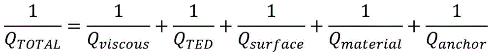
QanchorCorresponding to the energy loss from the resonant member 12 to the anchor 82. This energy loss can be coupled to another mode, leading to a ZRO result. For example, some energy may flow from the drive mode to the sense mode and cause a ZRO result. QTDCorresponds to the loss of energy from the resonant member 12 due to the interaction of the mechanical resonance and the thermal mode of the sensing device 10. The mechanical domain and the thermal domain are coupled to each other by a Coefficient of Thermal Expansion (CTE) that results in thermoelastic damping (TED).
If the decoupling mechanism 80 has a lower stiffness, energy becomes difficult to output from its resilient portions 88, 92, and QanchorEnergy loss can beAnd decreases. In this embodiment, the stiffness of each first resilient portion 88 is lower than the stiffness of each second resilient portion 92. The rigidity of each first elastic portion 88 can be reduced by reducing its size. For example, the thickness of each first elastic portion 88 and/or the circumferential width of the first connecting portion 96a, the body portion 96b, and/or the second connecting portion 96c may be reduced. Additionally or alternatively, the stiffness of each first elastic portion 88 may be reduced by using a material having a low modulus of elasticity. Although the rigidity of each first elastic portion 88 is low, the total rigidity of the first elastic portions 88 is high due to the large number thereof. Thus, QanchorEnergy losses may be reduced (due to the low stiffness of each first resilient portion 88) while ensuring (due to the overall stiffness of the first resilient portions 88) that the sensing device 10 is less susceptible to out-of-plane shock and vibration. Further, QanchorThe energy loss can be reduced by providing the fourth connection portion 98c of the second elastic portion 92 in the first direction of the crystal orientation of the resonance member and the second direction perpendicular to the crystal orientation. For example, in the present embodiment, the number of the fourth connecting portions 98c is four. The two fourth connecting portions 98c correspond to [110 ] of the resonance member 12]The first axis D1 of the crystal orientation direction is disposed, and the other two connecting portions 98c are disposed on the second axis D2 perpendicular to the first axis D1. QanchorEnergy losses can be reduced by reducing the stiffness of the flange 86 with the aperture 94.
Having a wider connection point to the resonant member 12 and a stiffer spring portion may improve QTEDSince it reduces the strain variations on this area during vibration. In the present embodiment, the rigidity of each second elastic portion 92 is greater than the rigidity of each first elastic portion 92. Thus, QTEDIs improved.
The ring portion 90 serves as a buffer. It combines the displacements of the resonant members 12 from different connection points and cancels each other, reducing the total displacement at the loop portion 90 and reducing any energy transferred to the anchor 82. Because the first elastic portion 88 and the second elastic portion 92 are connected via the loop portion 90, interference of the first elastic portion 88 and the second elastic portion 92 with each other may be possibleAnd decreases. Thus, the benefits of improved anchor loss at the first resilient portion 88 and improved Q at the second resilient portion 92 can be independently achievedTEDThe benefits of (1). Thus, decoupling mechanism 80 may improve anchor loss and QTEDAnd both.
The first elastic portions 88 in this embodiment each have a lower rigidity than that of each of the second elastic portions 92. Therefore, it is relatively easy to design decoupling mechanism 80 such that flange 86 and first resilient portion 88 have the benefit of improved anchor loss on the inside of ring portion 90, while the outside of ring portion 90 has an independent improvement in QTEDThe benefits of (1). It is to be appreciated that in some examples, the first resilient portion 88 may have a higher stiffness and the second resilient portion 92 may have a lower stiffness. However, if the decoupling mechanism 80 is designed to provide the first resilient portion 88 with high stiffness and the flange 86 with low stiffness through the aperture 94, it is difficult to achieve this independent benefit of the inboard and outboard sides of the ring portion 90.
The decoupling mechanism 80 in fig. 9 may be applied to any of the above embodiments in which the electrodes 18 are disposed outside the outer perimeter of the resonant member 12. Further, it is to be appreciated that the decoupling mechanism 80 may include various other structures. For example, the fourth connection portion 98c may be along a line such as [100 ]]Other crystal orientations of the resonant member 12 such as orientation are aligned. As another example, the decoupling mechanism may include a total of eight fourth connection portions 98 c. In such an example, some of the fourth connection portions 98c may be along [110 ] of the resonant member 12]Orientation aligned and others along [100 ]]The orientation is aligned. As the number of fourth connection portions 98c increases, the effect of thermoelastic damping increases, thereby providing a lower QTED. Other example structures for decoupling mechanism 80 are disclosed in the' 390 publication.
Fig. 10 shows an example structure for the anchor 82, in which the anchor 82 has a first region 102a made of polycrystalline silicon and a second region 102b made of single crystal silicon surrounded by the first region 102 a. The first region 102a connects the anchor 82 to the decoupling mechanism 80 and may provide an electrical connection between the sensing device 10 and the substrate 16. Meanwhile, a void 104 is formed below the second region 102b so that the entire bottom surface thereof is spaced apart from the substrate 16. During fabrication of anchor 82, second region 102b is connected to substrate 16 via silicon dioxide, and void 104 is created by later removal of the silicon dioxide. By connecting the anchor 82 and the substrate 16 only via the first region 102a, the stiffness of the anchor 82 is reduced, and there is a benefit of improving anchor loss.
Typically, a smaller anchor 82 will provide a smaller energy loss path and thus may aid in design. However, reducing the radius of the anchor 82 may make the sensing device 10 more susceptible to out-of-plane shock and vibration. Fig. 11 illustrates an embodiment of the anchor 82 in which a slit 106 is formed in the first region 102a to reduce the size of the anchor 82 without reducing its radius. Therefore, the energy loss at the anchor 82 is reduced.
The present application has been described with reference to the above exemplary embodiments. Modifications and alterations will occur to others upon a reading and understanding of this specification. Example embodiments including one or more aspects of the invention are intended to include all such modifications and alterations insofar as they come within the scope of the appended claims.
Claims (20)
1. A sensing device, comprising:
a resonant member movable in a first mode and a second mode; and
an electrode is arranged on the base plate and is provided with a plurality of electrodes,
wherein the resonance member has a capacitive surface portion facing and capacitively coupled to the capacitive surface portion of the electrode,
wherein the displacement of each point along the capacitive surface portion of the resonant member in the first mode is substantially tangential to that point.
2. The sensing apparatus of claim 1, wherein a capacitive surface portion of the resonating member is curved.
3. The sensing apparatus of claim 1, wherein the capacitive surface portion of the resonating member is concave.
4. The sensing apparatus of claim 1, wherein the capacitive surface portion of the resonating member is convex.
5. The sensing apparatus of claim 1, wherein:
the resonance member includes a main body and a protrusion integrally connected to and protruding from the main body, and
the protrusion defines a capacitive surface portion of the resonant member.
6. The sensing apparatus of claim 5, wherein:
the protrusion extends from the body along a nodal axis of the resonant member,
the projection includes a proximal portion and a distal portion, the distal portion being wider than the proximal portion, and
the distal end portion defines a capacitive surface portion of the resonant member.
7. The sensing device of claim 6, wherein the proximal end portion of the protrusion is connected to a portion of the body that is displaced in a direction substantially parallel to the nodal axis in the second mode.
8. The sensing apparatus of claim 1, wherein the resonating member comprises a body and the capacitive surface portion of the resonating member is a recessed surface portion of the body.
9. The sensing device of claim 1, further comprising:
a substrate;
an anchor supporting the resonant member relative to the substrate; and
a decoupling mechanism for flexibly decoupling the resonant member from the anchor,
wherein the decoupling mechanism comprises: a flange connected to the anchor; a ring portion; a plurality of first elastic portions connecting the ring portion to the flange; and a plurality of second elastic parts connecting the loop part to the resonance member, and
each of the first elastic portions has a rigidity lower than that of each of the second elastic members.
10. A gyroscope comprising the sensing device of claim 1.
11. A sensing device, comprising:
a resonant member movable in a first mode and a second mode; and
an electrode is arranged on the base plate and is provided with a plurality of electrodes,
wherein the electrode is arranged between the two capacitive surface portions of the resonance member such that one of the two capacitive surface portions of the resonance member faces and is capacitively coupled to the one capacitive surface portion of the electrode and the other of the two capacitive surface portions of the resonance member faces and is capacitively coupled to the other capacitive surface portion of the electrode, and
the displacement of each point along each of the two capacitive surface portions of the resonant member in the first mode is substantially tangential to that point.
12. The sensing apparatus of claim 11, wherein:
the electrode and the resonant member defining a capacitive channel between the electrode and the resonant member, and
the two capacitive surface portions of the resonant member define two end portions of the capacitive channel, respectively.
13. The sensing apparatus of claim 11, wherein:
the resonance member includes a main body and two protrusions integrally connected to and protruding from the main body,
the electrode is disposed between the two projections,
one of the two protrusions defines one of the two capacitive surface portions of the resonant member and the other of the two protrusions defines the other of the two capacitive surface portions of the resonant member.
14. The sensing apparatus of claim 11, wherein the resonating member comprises a body, and each capacitive surface portion of the resonating member corresponds to a recessed surface portion of the body.
15. The sensing apparatus of claim 11, wherein the electrodes are disposed along a nodal axis of the resonating member.
16. A sensing device, comprising:
a resonant member movable in a first mode and a second mode, the resonant member comprising a main body and a protrusion extending from the main body along a nodal axis of the resonant member,
wherein the protrusion comprises a proximal portion and a distal portion, the distal portion being wider than the proximal portion.
17. The sensing device of claim 16, further comprising an electrode aligned with the protrusion along the nodal axis, wherein the proximal portion of the protrusion defines a capacitive surface portion of the resonating member that faces and is capacitively coupled to a capacitive surface portion of the electrode.
18. The sensing device of claim 16, wherein the proximal end portion of the protrusion is connected to a portion of the body that is displaced in a direction substantially parallel to the nodal axis in the second mode.
19. The sensing apparatus of claim 16, wherein the displacement of each point along the capacitive surface portion of the resonant member in the first mode is substantially tangential to that point.
20. The sensing apparatus of claim 19, wherein a capacitive surface portion of the resonating member is curved.
Applications Claiming Priority (7)
| Application Number | Priority Date | Filing Date | Title |
|---|---|---|---|
| US201962789550P | 2019-01-08 | 2019-01-08 | |
| US201962789549P | 2019-01-08 | 2019-01-08 | |
| US201962789548P | 2019-01-08 | 2019-01-08 | |
| US62/789,548 | 2019-01-08 | ||
| US62/789,549 | 2019-01-08 | ||
| US62/789,550 | 2019-01-08 | ||
| PCT/JP2019/051459 WO2020145203A1 (en) | 2019-01-08 | 2019-12-27 | Sensing device |
Publications (2)
| Publication Number | Publication Date |
|---|---|
| CN113196009A true CN113196009A (en) | 2021-07-30 |
| CN113196009B CN113196009B (en) | 2024-11-01 |
Family
ID=71521223
Family Applications (1)
| Application Number | Title | Priority Date | Filing Date |
|---|---|---|---|
| CN201980083356.7A Active CN113196009B (en) | 2019-01-08 | 2019-12-27 | Sensing device |
Country Status (5)
| Country | Link |
|---|---|
| US (1) | US11725941B2 (en) |
| EP (1) | EP3908803A4 (en) |
| JP (1) | JP7474931B2 (en) |
| CN (1) | CN113196009B (en) |
| WO (1) | WO2020145203A1 (en) |
Families Citing this family (2)
| Publication number | Priority date | Publication date | Assignee | Title |
|---|---|---|---|---|
| US12388411B2 (en) * | 2022-12-02 | 2025-08-12 | Panasonic Intellectual Property Management Co., Ltd. | Single anchor resonators |
| US20250116517A1 (en) * | 2023-10-06 | 2025-04-10 | Panasonic Intellectual Property Management Co., Ltd. | Apparatus and method for quadrature reduction in vibratory gyroscopes |
Citations (8)
| Publication number | Priority date | Publication date | Assignee | Title |
|---|---|---|---|---|
| US5650568A (en) * | 1993-02-10 | 1997-07-22 | The Charles Stark Draper Laboratory, Inc. | Gimballed vibrating wheel gyroscope having strain relief features |
| JP2002515976A (en) * | 1996-05-31 | 2002-05-28 | ザ リージェンツ オブ ザ ユニヴァーシティ オブ カリフォルニア | Ultra-small precision vibration rate gyroscope |
| US6443008B1 (en) * | 2000-02-19 | 2002-09-03 | Robert Bosch Gmbh | Decoupled multi-disk gyroscope |
| CN1954188A (en) * | 2004-03-12 | 2007-04-25 | 松下电工株式会社 | Gyro sensor and sensor device using the gyro sensor |
| WO2009057990A2 (en) * | 2007-10-31 | 2009-05-07 | Mimos Berhad | Capacitive area-changed mems gyroscope with adjustable resonance frequencies |
| CN104931032A (en) * | 2015-06-26 | 2015-09-23 | 清华大学 | Single-anchoring-point quadruple-mass MEMS (micro-electro-mechanical systems) resonant gyroscope |
| US20160164458A1 (en) * | 2011-10-20 | 2016-06-09 | The Regents Of The University Of California | Hollow supports and anchors for mechanical resonators |
| CN108955662A (en) * | 2018-04-27 | 2018-12-07 | 苏州大学 | Resonator gyroscope substantially symmetrical about its central axis with frequency difference adjustment structure |
Family Cites Families (26)
| Publication number | Priority date | Publication date | Assignee | Title |
|---|---|---|---|---|
| US4872342A (en) * | 1986-06-27 | 1989-10-10 | Sundstrand Data Control, Inc. | Translational accelerometer and accelerometer assembly method |
| FR2700014B1 (en) * | 1992-12-08 | 1995-04-28 | Commissariat Energie Atomique | Capacitive sensor sensitive to accelerations oriented in all directions of a plane. |
| US5555765A (en) * | 1993-02-10 | 1996-09-17 | The Charles Stark Draper Laboratory, Inc. | Gimballed vibrating wheel gyroscope |
| US5635640A (en) * | 1995-06-06 | 1997-06-03 | Analog Devices, Inc. | Micromachined device with rotationally vibrated masses |
| DE19523895A1 (en) * | 1995-06-30 | 1997-01-02 | Bosch Gmbh Robert | Acceleration sensor |
| US6367326B1 (en) * | 1996-07-10 | 2002-04-09 | Wacoh Corporation | Angular velocity sensor |
| DE69634571D1 (en) * | 1996-07-10 | 2005-05-12 | Wako Kk | ROTARY SPEED SENSOR |
| DE19938206A1 (en) * | 1999-08-12 | 2001-02-15 | Bosch Gmbh Robert | Micro-mechanical rotational acceleration sensor has an oscillating mass fixed at its center with an array of differential measurement capacitors for determination of acceleration directly rather than using time differentiation |
| JP2004279384A (en) * | 2003-03-19 | 2004-10-07 | Sumitomo Precision Prod Co Ltd | Vibrator manufacturing method, vibrator and photomask |
| JP2006078444A (en) * | 2004-09-13 | 2006-03-23 | Hosiden Corp | Acceleration sensor |
| US7543496B2 (en) | 2006-03-27 | 2009-06-09 | Georgia Tech Research Corporation | Capacitive bulk acoustic wave disk gyroscopes |
| US7578189B1 (en) | 2006-05-10 | 2009-08-25 | Qualtre, Inc. | Three-axis accelerometers |
| US8042394B2 (en) * | 2007-09-11 | 2011-10-25 | Stmicroelectronics S.R.L. | High sensitivity microelectromechanical sensor with rotary driving motion |
| US8528404B2 (en) | 2007-10-11 | 2013-09-10 | Georgia Tech Research Corporation | Bulk acoustic wave accelerometers |
| JP5247182B2 (en) * | 2008-02-19 | 2013-07-24 | キヤノン株式会社 | Angular velocity sensor |
| IT1391972B1 (en) * | 2008-11-26 | 2012-02-02 | St Microelectronics Rousset | MICROELETTROMECHANICAL GYROSCOPE WITH ROTARY DRIVE MOVEMENT AND IMPROVED ELECTRICAL CHARACTERISTICS |
| IT1391973B1 (en) * | 2008-11-26 | 2012-02-02 | St Microelectronics Rousset | MONO OR BIASSIAL MICROELECTROMECHANICAL GYROSCOPE WITH INCREASED SENSITIVITY TO THE ANGULAR SPEED DETECTION |
| US8205497B1 (en) * | 2009-03-05 | 2012-06-26 | Sandia Corporation | Microelectromechanical inertial sensor |
| EP2573516B1 (en) * | 2011-09-21 | 2013-11-20 | Tronics Microsystems S.A. | A micro-electromechanical gyro device |
| US8448513B2 (en) * | 2011-10-05 | 2013-05-28 | Freescale Semiconductor, Inc. | Rotary disk gyroscope |
| EP2607849A1 (en) * | 2011-12-22 | 2013-06-26 | Tronics Microsystems S.A. | Multiaxial micro-electronic inertial sensor |
| FI126070B (en) * | 2014-01-28 | 2016-06-15 | Murata Manufacturing Co | Improved ring gyroscope structure and gyroscope |
| US9923545B2 (en) | 2014-10-22 | 2018-03-20 | Microchip Technology Incorporated | Compound spring MEMS resonators for frequency and timing generation |
| WO2017075413A1 (en) * | 2015-10-28 | 2017-05-04 | Georgia Tech Research Corporation | Comb-driven substrate decoupled annulus pitch/roll baw gyroscope with slanted quadrature tuning electrode |
| US10921123B2 (en) * | 2016-06-07 | 2021-02-16 | Georgia Tech Research Corporation | Pitch/roll annulus gyroscope with slanted quadrature tuning electrodes and related fabrication methods |
| JP6769517B2 (en) * | 2018-05-08 | 2020-10-14 | 株式会社村田製作所 | Piezo ring gyroscope |
-
2019
- 2019-12-27 CN CN201980083356.7A patent/CN113196009B/en active Active
- 2019-12-27 JP JP2021529286A patent/JP7474931B2/en active Active
- 2019-12-27 WO PCT/JP2019/051459 patent/WO2020145203A1/en not_active Ceased
- 2019-12-27 EP EP19908106.8A patent/EP3908803A4/en active Pending
- 2019-12-27 US US17/420,751 patent/US11725941B2/en active Active
Patent Citations (8)
| Publication number | Priority date | Publication date | Assignee | Title |
|---|---|---|---|---|
| US5650568A (en) * | 1993-02-10 | 1997-07-22 | The Charles Stark Draper Laboratory, Inc. | Gimballed vibrating wheel gyroscope having strain relief features |
| JP2002515976A (en) * | 1996-05-31 | 2002-05-28 | ザ リージェンツ オブ ザ ユニヴァーシティ オブ カリフォルニア | Ultra-small precision vibration rate gyroscope |
| US6443008B1 (en) * | 2000-02-19 | 2002-09-03 | Robert Bosch Gmbh | Decoupled multi-disk gyroscope |
| CN1954188A (en) * | 2004-03-12 | 2007-04-25 | 松下电工株式会社 | Gyro sensor and sensor device using the gyro sensor |
| WO2009057990A2 (en) * | 2007-10-31 | 2009-05-07 | Mimos Berhad | Capacitive area-changed mems gyroscope with adjustable resonance frequencies |
| US20160164458A1 (en) * | 2011-10-20 | 2016-06-09 | The Regents Of The University Of California | Hollow supports and anchors for mechanical resonators |
| CN104931032A (en) * | 2015-06-26 | 2015-09-23 | 清华大学 | Single-anchoring-point quadruple-mass MEMS (micro-electro-mechanical systems) resonant gyroscope |
| CN108955662A (en) * | 2018-04-27 | 2018-12-07 | 苏州大学 | Resonator gyroscope substantially symmetrical about its central axis with frequency difference adjustment structure |
Non-Patent Citations (1)
| Title |
|---|
| HANSONG, ZENG等: "Sensing movement: microsensors for body motion measurement", SENSORS, vol. 11, no. 1, 10 January 2011 (2011-01-10), pages 638 - 660 * |
Also Published As
| Publication number | Publication date |
|---|---|
| US11725941B2 (en) | 2023-08-15 |
| JP7474931B2 (en) | 2024-04-26 |
| US20220316881A9 (en) | 2022-10-06 |
| CN113196009B (en) | 2024-11-01 |
| WO2020145203A1 (en) | 2020-07-16 |
| JP2022515971A (en) | 2022-02-24 |
| US20220107181A1 (en) | 2022-04-07 |
| EP3908803A1 (en) | 2021-11-17 |
| EP3908803A4 (en) | 2022-07-20 |
Similar Documents
| Publication | Publication Date | Title |
|---|---|---|
| US8733172B2 (en) | Microelectromechanical gyroscope with rotary driving motion and improved electrical properties | |
| US8042396B2 (en) | Microelectromechanical sensor with improved mechanical decoupling of sensing and driving modes | |
| CN112739982B (en) | Drive and sense balance, fully coupled 3-axis gyroscope | |
| JP4392246B2 (en) | Micromachined gyroscope | |
| US10746548B2 (en) | Ring gyroscope structural features | |
| CN103712612B (en) | Acceleration and angular velocity resonance detection integrated structure and related MEMS sensor equipment | |
| TWI647425B (en) | Improved gyroscope structure and gyroscope | |
| US20020189352A1 (en) | Mems sensor with single central anchor and motion-limiting connection geometry | |
| CN107636419B (en) | Vibrating micromechanical sensor of angular velocity and method for operating same | |
| US9091544B2 (en) | XY-axis shell-type gyroscopes with reduced cross-talk sensitivity and/or mode matching | |
| US8479574B2 (en) | Micro scale mechanical rate sensors | |
| EP1014037A1 (en) | Spring for a resonance ring of an angular rate sensor | |
| TW528870B (en) | Counterbalanced silicon tuned multiple accelerometer-gyro | |
| US20160327390A1 (en) | Method and apparatus for decoupling environmental and modal dependencies in inertial measurement devices | |
| CN113196009B (en) | Sensing device | |
| JPH085382A (en) | Angular-velocity sensor | |
| US11614328B2 (en) | Sensing device | |
| US9303994B2 (en) | Planar Coriolis gyroscope | |
| CN116940804A (en) | Vibrating gyroscope with planar structure |
Legal Events
| Date | Code | Title | Description |
|---|---|---|---|
| PB01 | Publication | ||
| PB01 | Publication | ||
| SE01 | Entry into force of request for substantive examination | ||
| SE01 | Entry into force of request for substantive examination | ||
| GR01 | Patent grant | ||
| GR01 | Patent grant |