CN113156084A - A series connection anchor law of motion test device for among hypergravity centrifuge - Google Patents
A series connection anchor law of motion test device for among hypergravity centrifuge Download PDFInfo
- Publication number
- CN113156084A CN113156084A CN202110302276.5A CN202110302276A CN113156084A CN 113156084 A CN113156084 A CN 113156084A CN 202110302276 A CN202110302276 A CN 202110302276A CN 113156084 A CN113156084 A CN 113156084A
- Authority
- CN
- China
- Prior art keywords
- anchor
- centrifuge
- model box
- test
- magnetic induction
- Prior art date
- Legal status (The legal status is an assumption and is not a legal conclusion. Google has not performed a legal analysis and makes no representation as to the accuracy of the status listed.)
- Pending
Links
Images


Classifications
-
- G—PHYSICS
- G01—MEASURING; TESTING
- G01N—INVESTIGATING OR ANALYSING MATERIALS BY DETERMINING THEIR CHEMICAL OR PHYSICAL PROPERTIES
- G01N33/00—Investigating or analysing materials by specific methods not covered by groups G01N1/00 - G01N31/00
- G01N33/24—Earth materials
Landscapes
- Life Sciences & Earth Sciences (AREA)
- Health & Medical Sciences (AREA)
- Engineering & Computer Science (AREA)
- Chemical & Material Sciences (AREA)
- Food Science & Technology (AREA)
- Analytical Chemistry (AREA)
- Geology (AREA)
- General Life Sciences & Earth Sciences (AREA)
- Environmental & Geological Engineering (AREA)
- Medicinal Chemistry (AREA)
- Physics & Mathematics (AREA)
- Remote Sensing (AREA)
- Biochemistry (AREA)
- General Health & Medical Sciences (AREA)
- General Physics & Mathematics (AREA)
- Immunology (AREA)
- Pathology (AREA)
- Investigating Strength Of Materials By Application Of Mechanical Stress (AREA)
Abstract
The invention discloses a serial anchor motion law testing device for a centrifuge. The test system mainly comprises a centrifuge model box, a test series anchor model, a plurality of magnetic induction sensors, a magnetic source, a force sensor and a load loading system; the whole set of device simulates the installation process of the series anchor in a centrifuge test aiming at different initial embedding angles and depths and initial conditions such as anchoring modes in the series anchor, so that the embedding track and attitude information of the series anchor are obtained. The method can simulate the dragging and mounting process of the series anchor in a centrifuge test aiming at different initial embedding angles and depths and anchoring modes in the series anchor, thereby obtaining the embedding track and attitude information of the series anchor and solving the problem that the running track of the series anchor in the soil body is difficult to continuously and accurately measure.
Description
Technical Field
The invention relates to a test device for measuring the motion and the posture of an anchor body and an anchor cable in the installation process of a series anchor on a hypergravity centrifugal machine.
Background
The 'ocean strong national strategy' requires that China improves the ocean resource development capability, and in addition, the reserves of oil and gas resources in four sea areas of China are huge, so the demand on an offshore oil and gas exploitation platform is greatly increased. With the exploitation of oil and gas resources from shallow sea to deep sea, the ocean platform is transformed from a traditional fixed platform to novel structures such as a Tension Leg Platform (TLP) and a Floating Production Storage and Offloading (FPSO), and the foundation form is also transformed from a large-diameter single pile to a towing anchor, a normal bearing anchor and the like. As a novel mixed anchor, the series anchor not only keeps the advantages of light weight, material saving, easy installation, recoverability, repeated use and the like of the traditional flat plate anchor, but also overcomes the defects of easy overturn, shallow limit embedding depth, low bearing capacity and the like of the embedding process of the traditional flat plate anchor, and becomes a direction of the future offshore platform foundation preference.
The series anchor is a novel mixed anchor formed by combining two or more traditional flat plate anchors, such as a drag anchor or a normal bearing anchor. The bearing capacity is similar to that of the traditional flat anchor, and the penetration depth and the posture in the soil body are often the determining factors. Therefore, accurate prediction of the penetration track and the attitude information of the anchor body in the installation process is the primary condition for determining the bearing capacity of the anchor body. However, for the serial anchors, there are few data on how to accurately measure the movement track of the anchor plate in the soil body in the installation process, and a study on how to observe the installation process in real time is not developed yet. In addition, the serial anchors are subjected to various cyclic loads such as wind, waves and flow for a long time in the service process, and the basic failure process and the instability modes of the front anchor and the piggyback anchor need to be researched and verified through tests. Therefore, research on the motion rule and the damage mechanism of the installation process and the service state of the series anchor through a test means is a current scientific research requirement.
Due to invisibility of the soil body, it becomes a great technical difficulty to accurately obtain the motion trail and posture change information of the serial anchors in the test of the natural soil body. The current measuring means and method for the motion trail of the anchor plate can not completely solve the difficulty, and mainly comprises (1) observing the motion information of the flat plate anchor in the flat plate anchor by utilizing the transparency of the synthetic lithium bentonite; (2) smearing potassium permanganate on the flat anchor to enable the flat anchor to generate a dark red track when the flat anchor moves in a natural soil body; (3) and measuring the angle change of the flat anchor in the natural soil body by using the inclination angle sensor. The test materials of the measuring means are far from the marine soil quality, or all the motion information of the track and the attitude of the serial anchor cannot be simultaneously and accurately obtained, so that the measuring means has certain limitations.
Disclosure of Invention
In order to solve the problems in the prior art, the invention provides a device and a method for testing the motion law of a series anchor in a hypergravity centrifuge, provides a basic test scheme for disclosing the coupling effect test of a front anchor and a back-carrying anchor, and solves the problem of test detection of the coupling effect of the front anchor and the back-carrying anchor which is not solved in the prior art.
The device can measure the motion trail and the attitude information of the serial anchor in real time through the magnetic induction positioning system, and completely solves the technical difficulty that the motion information of the flat anchor is difficult to accurately measure in the natural soil body due to the invisibility of the soil body. The invention can be used for a hypergravity centrifuge test, compensates the self weight loss of the soil body caused by the reduction of the size of the model, and ensures that the model soil body can duplicate the stress state of the original soil body, thereby more accurately simulating the installation and service process of the series anchor.
The invention mainly comprises a centrifuge model box, a test series anchor model (comprising a front anchor and a back anchor), a plurality of magnetic induction sensors, a magnetic source, a force sensor and a load loading system. The whole set of device can simulate the installation process of the series anchor in a hypergravity centrifuge test aiming at different initial embedding angles and depths and initial conditions such as an anchoring mode inside the series anchor, so that the embedding track and the posture information of the series anchor are obtained.
The invention adopts the following technical scheme for solving the technical problems:
the test device system comprises four parts which are used for a centrifuge test centrifuge model box, a series connection anchor system, a magnetic induction positioning system and a load loading test system: the test soil is filled in the centrifuge model box, the serial anchor system is arranged in the test soil in the centrifuge model box, one part of the magnetic induction positioning system is arranged in the hypergravity centrifuge model box, the other part of the magnetic induction positioning system is arranged outside the hypergravity centrifuge model box, and the load loading and testing system is arranged at the upper port of the hypergravity centrifuge model box; the series anchor system is connected with the load loading and testing system, and the magnetic induction positioning system is connected with the series anchor system and the load loading and testing system.
The magnetic induction positioning system sensor is fixed on a series anchor in a centrifuge model box, the data processing and controlling part is arranged at the middle end of a rotating arm of the centrifuge, and the load loading test system is arranged in the centrifuge model box through a cross beam; the load loading test system drags the series anchor through the anchor cable and measures the load; and the magnetic induction positioning system measures the motion and attitude information of the serial anchor in the test process.
The series anchor system comprises a front anchor, a back anchor, a first anchor cable connecting the front anchor and the back anchor, and a second anchor cable connecting the load loading test system and the front anchor, wherein the front anchor and the back anchor are both buried in test soil, and the front anchor and the back anchor are connected through the first anchor cable.
The load loading test system is connected with the series anchor through a second anchor cable and comprises a pulley, a force sensor and a motor; a cross beam is erected at an upper port of the model box of the hypergravity centrifuge, a motor is installed on the cross beam, a box cover small hole is formed in the cross beam, a vertical support frame is installed in the box cover small hole, the lower end of the vertical support frame extends into the model box of the hypergravity centrifuge, a pulley and a dynamometer are installed on the vertical support frame in the model box of the hypergravity centrifuge, the output end of the motor is fixedly connected with one end of a second anchor rope, and the other end of the second anchor rope is connected to a front anchor after being wound by the pulley and the dynamometer; the motor bearing is provided with a roller, an anchor rope is loaded through rotation, the anchor rope is connected with a force sensor through a pulley on the upper portion of a pulley support, and the other end of the force sensor is connected with a series anchor front anchor through a second anchor rope and a pulley on the lower portion of the pulley support. The motor realizes loading, the pulley changes the loading direction, and the force sensor measures the load.
The magnetic induction positioning system comprises a magnetic source, a magnetic induction sensor, a data processing and controlling part, a magnetic source bracket, a data terminal computer and a power supply; the magnetic source is arranged at the center in the model box of the hypergravity centrifuge through a magnetic source bracket, and magnetic induction sensors are uniformly arranged on the front anchor, the back anchor, the first anchor cable and the second anchor cable; the data processing and control part, the data terminal computer and the power supply are all located outside the model box of the supergravity centrifuge, the magnetic source and the magnetic induction sensor are both connected to the data processing and control part, and the data processing and control part is respectively connected to the data terminal computer and the power supply.
The cross beam is fixed at a specific position of the model box through cross beam side plates at two sides of the model box and screws and is immovable.
The pulley bracket, the magnetic source bracket and the motor bracket are fixedly arranged at the designated position of the cross beam through screws; the upper end and the lower end of the pulley support are provided with pulleys, the magnetic source support is provided with a magnetic source which is positioned at the center of the model box of the centrifugal machine, and the motor support is used for fixing a motor to load an anchor cable.
In the serial anchor system, the front anchor is a towing anchor, the back-carrying anchor is a normal bearing anchor, the two anchors are connected through a first anchor cable, and the front anchor is connected with the load loading test system through a second anchor cable.
The centrifuge model box is made of aluminum alloy.
The distance between the magnetic source, the magnetic induction sensor and the wall of the model box is more than 300mm so as to avoid the influence of the metal mold box on a magnetic induction positioning system, and the internal dimension of the model box is 1200mm (length) multiplied by 950mm (width) multiplied by 1000mm (height).
The model box of the hypergravity centrifugal machine is fixedly arranged at the bottom of a hanging basket of the hypergravity centrifugal machine.
The invention mainly comprises a centrifuge model box, a test series anchor model (comprising a front anchor and a back anchor), an anchor cable, a plurality of magnetic induction sensors, a magnetic source, a force sensor and a load loading system. The test soil is filled in a centrifuge model box, the serial anchors are arranged in the test soil, magnetic induction sensors are fixedly arranged on the front anchor plate and the back anchor plate, the miniature magnetic induction sensors are also arranged at different positions of the anchor cable, and the force sensor is arranged close to the loading end. The load loading system applies pulling force to the anchor cable to simulate the installation and service process of the series anchor, and meanwhile, the force sensor and the magnetic induction sensor respectively obtain pulling force data of the anchor cable and motion data of the series anchor system.
The invention is used for the series anchor test of the hypergravity centrifugal machine, the model box of the hypergravity centrifugal machine should meet a certain size to avoid the interference of metal to a magnetic induction positioning system, thereby improving the precision of the magnetic induction positioning system, continuously detecting the high-precision motion information of the anchor plate and the anchor cable of the series anchor in real time, and determining the three-dimensional space position and the attitude information of the anchor plate and the anchor cable in the test.
Compared with the prior art, the invention has the beneficial effects that:
1. the invention can be used for the test of the hypergravity centrifuge, thereby compensating the self weight loss of the soil body caused by the reduction of the size of the model, enabling the test model soil body to duplicate the stress state of the original soil body, and further more accurately simulating the installation and service process of the series anchor.
2. The invention adopts a magnetic induction positioning system, and can simultaneously track all the motion information of six degrees of freedom of a front anchor, a piggyback anchor, an anchor cable and the like. Compared with the prior tilt sensor method and the transparent soil method, the obtained motion information is more comprehensive and accurate, and the operation is more convenient.
Drawings
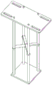
Fig. 1 is a front sectional view (view from front to back) of the present invention.
Fig. 2 is a top view of the present invention.
FIG. 3 is a schematic view of a magnetic induction positioning system of the present invention.
Figure 4 is a schematic view of a tandem anchor system and magnetic induction sensor arrangement of the present invention.
Fig. 5 is a schematic view of a magnetic source mount of the present invention.
Figure 6 is a schematic view of the sheave bracket of the present invention.
FIG. 7 shows the magnetic field strength inside the mold box when the centrifuge is in operation.
FIG. 8 is an illustration of the effect of centrifuge operation on magnetic induction positioning system measurements.
FIG. 9 shows the effect of the test pattern box on the magnetic induction positioning system measurements.
In the figure: 1. the model box comprises a hypergravity centrifuge model box body, 2, test soil, 3, a cross beam, 4, a cross beam side plate, 5, a magnetic source support, 6, a magnetic source, 7, a pulley support, 8, a pulley, 9, a force sensor, 10, a motor support, 11, a motor, 12, a roller, 13, a front anchor, 14, a piggyback anchor, 15, a second anchor cable, 16, a first anchor cable, 17, a magnetic induction sensor, 18, a data processing and control part, 19, a power supply and 20 a terminal computer.
Detailed Description
The invention is further illustrated by the following figures and examples.
As shown in fig. 1-2, the test apparatus system comprises a test model box 1 with an internal dimension of more than 600mm for a hypergravity centrifuge test, a series connection anchor system, a magnetic induction positioning system, and a load loading test system: the test soil 2 is arranged in the model box 1 of the hypergravity centrifuge, the series anchor system is arranged in the test soil 2 in the model box 1 of the hypergravity centrifuge, one part of the magnetic induction positioning system is arranged in the model box 1 of the hypergravity centrifuge, the other part is arranged outside the model box 1 of the hypergravity centrifuge, and the load loading test system is arranged at the upper port of the model box 1 of the hypergravity centrifuge; the series anchor system is connected with the load loading test system, and the magnetic induction positioning system is connected with the series anchor system and the load loading test system. Specifically, a magnetic induction positioning system sensor 17 is fixed on a series anchor in a model box, a data processing and control part 18 is arranged at the middle end of a rotating wall of a centrifuge, and a load loading test system is arranged in the model box through a cross beam 3; the load loading system drags the series anchor through the anchor line 15 and measures the load; and the magnetic induction positioning system measures the motion and attitude information of the serial anchor in the test process.
As shown in fig. 4, the series anchor system includes a front anchor 13, a piggyback anchor 14, a first anchor cable 16 connecting the front anchor 13 and the piggyback anchor 14, and a second anchor cable 15 connecting the load loading test system and the front anchor 13, the front anchor 13 and the piggyback anchor 14 are both buried in the test soil 2, and the front anchor 13 and the piggyback anchor 14 are connected by the first anchor cable 16;
the load loading test system is connected to the anchor cable 5 in the series anchor system 2 and comprises a force sensor 13, a pulley 12 and a motor 14; a cross beam 10 is erected at the upper port of a supergravity centrifuge model box 1, a motor 14 is installed on the cross beam 10, a box cover small hole is formed in the cross beam 10, a vertical supporting frame 11 is installed in the box cover small hole, the lower end of the vertical supporting frame 11 extends into the supergravity centrifuge model box 1, a pulley 12 and a force sensor 13 are installed on the vertical supporting frame 11 in the supergravity centrifuge model box 1, two pulleys 12 and one force sensor 13 are arranged in the specific implementation, the two pulleys 12 are respectively located on the upper side and the lower side of the force sensor 13, the output end of the motor 14 is fixedly connected with one end of a second anchor cable 18, and the other end of the second anchor cable 18 is connected to a front anchor 13 after being wound by the pulley 12 and the force sensor 13.
In specific implementation, two beams 3 are arranged on the top surface of a model box 1 of a supergravity centrifuge, and a pulley bracket 7, a magnetic source bracket 5 and a motor bracket 10 are arranged on the beams 3; a pulley bracket 7 applies load to the anchor cable 15 through two pulleys 8; the force sensor 9 is arranged between the two pulleys to test the tension of the anchor cable. The motor support is provided with a motor 11, and the motor 11 applies pulling force to the anchor cable through the rotation of the roller
As shown in fig. 3, the magnetic induction positioning system includes a magnetic source 6, a magnetic induction sensor 17, a data processing and controlling part 18, a magnetic source support 5, a data terminal computer 20 and a power supply 19. The magnetic source 6 is arranged in the center of the model box 1 of the hypergravity centrifuge through a magnetic source bracket 5, the magnetic source bracket 5 is fixed on a cross beam 3 of the model box 1 of the hypergravity centrifuge, and magnetic induction sensors 17 are uniformly arranged on a front anchor 13, a back-carrying anchor 14, a first anchor cable 16 and a second anchor cable 15; the data processing and control part 18, the data terminal computer 20 and the power supply 19 are all located outside the model box 1 of the supergravity centrifuge, as shown in fig. 3, the magnetic source 6 and the magnetic induction sensor 17 are led out through data lines and are all connected to the data processing and control part 18, and the data processing and control part 18 is respectively connected to the data terminal computer 20 and the power supply 19.
In the magnetic induction positioning system, a magnetic source 6 is fixedly arranged on a magnetic source bracket 5 through a plastic screw, the magnetic source bracket 5 adopts an epoxy resin bracket, and the magnetic source bracket 5 is fixed on a cross beam 3 of a model box 1 of the supergravity centrifuge.
The magnetic induction sensors 17 are respectively installed on the piggyback anchor 14, the front anchor 13, the anchor plate and the anchor cables 15 and 16 and are used for measuring the motion information of the anchor plate and the anchor cables.
In one embodiment, the data processing and control unit 18 is fixed to the middle of the rotating wall of the high-gravity centrifuge to reduce the influence of the high gravity on the electronic components.
In the serial anchor system, the front anchor 13 is a towing anchor, the back anchor 14 is a normal bearing anchor, the two anchors are connected by an anchor cable 16, and the connection mode and position can be determined according to the test requirements. The other anchor line 16 is connected to the front anchor and the load loading system, i.e. via two pulleys 8, and finally to the motor 11.
In specific implementation, the model box 1 of the supergravity centrifuge is made of a metal composite material, and the material is formed by rolling and compounding iron-nickel alloy, aluminum and iron-nickel alloy, so that electromagnetic fields with different frequencies can be effectively shielded.
In specific implementation, the model box 1 of the supergravity centrifuge has an electromagnetic shielding function, and the materials are iron-nickel alloy, aluminum and iron-nickel alloy which are high-permeability materials from outside to inside in sequence, so that electromagnetic fields with different frequencies can be effectively shielded. Through the shunting effect of the multiple layers of high-permeability materials on the low-frequency magnetic field, the good conductor aluminum material generates eddy currents to offset the high-frequency electromagnetic field, so that the hypergravity centrifuge model box can effectively shield the electromagnetic field in a larger frequency range.
The outer wall of the hypergravity centrifuge model box 1 is grounded through a lead 15, so that the shielding effect can be enhanced.
FIGS. 1-2 are two perspective views of the present invention, clearly showing a hypergravity centrifuge mold box.
An electromagnetic field with unknown frequency is generated in the running process of the supergravity centrifugal machine, and the electromagnetic positioning system is influenced. The iron-nickel alloy with the nickel content of 35-90% (the iron-nickel alloy with the nickel content is also called permalloy) has high magnetic conductivity, and can shield a low-frequency magnetic field through the shunting action of magnetic induction lines; and the good conductor aluminum alloy can shield a high-frequency magnetic field through an eddy current effect, so that the material combination of the iron-nickel alloy, the aluminum and the iron-nickel alloy can shield an electromagnetic field with a larger range of frequency, and a good non-magnetic environment is provided for a magnetic induction positioning system. Under the condition of low electromagnetic shielding requirement, iron-nickel alloy with proper thickness can be adhered to two sides of the wall of the aluminum supergravity centrifuge model box to achieve a certain electromagnetic shielding effect.
FIG. 3 is an electrical connection diagram of a magnetic induction positioning system, which is based on the principle that a data processing and control part generates a control signal, and a magnetic source is an orthogonal three-axis coil and is controlled by the control signal to emit an electromagnetic field to the periphery in a time-sharing manner. The magnetic induction sensor receives electromagnetic field signals, data are transmitted into a data terminal computer after A/D conversion, and position and attitude information of a target object, including translation in the direction of the target X, Y, Z and rotation around three main shafts, is calculated through an electromagnetic positioning algorithm.
Fig. 5 and 6 respectively show a pulley bracket and a magnetic source bracket, pulleys are arranged at the upper end and the lower end of the pulley bracket and used for changing the loading direction of an anchor line, a force sensor is positioned between the two pulleys, one end of the force sensor is connected with a motor drum through an anchor cable, and the other end of the force sensor is connected with a series anchor front anchor. The magnetic source support is made of organic glass and is arranged inside the model box through the cross beam, so that the magnetic source can be positioned in the center of the model box to avoid the influence of the metal model box on the magnetic induction positioning system.
FIG. 7 shows the magnetic field intensity inside the model box at maximum of about 5Gs when the centrifuge is in operation; fig. 8 is the test data of the magnetic induction positioning system during the operation of the centrifuge, and it can be known from the figure that the measurement result of the magnetic induction positioning system is stable in the g value stable section of the test. Therefore, the magnetic field generated by the operation of the centrifuge has negligible influence on the magnetic induction positioning system.
Fig. 8 and 9 show the influence of an aluminum model box on a magnetic induction positioning system, and the effective working range of the magnetic induction positioning system can reach about 600mm under the condition that the distance between a magnetic source, a magnetic induction sensor and the wall of the model box is kept at 300mm, which is enough for the conventional supergravity centrifugal model test.
Therefore, through the implementation of the device, aiming at different initial embedding angles and depths and anchoring modes in the series anchors, the dragging and mounting process of the series anchors is simulated in the hypergravity centrifuge test, so that the embedding track and the posture information are obtained, the problem that the running track of the series anchors in a soil body is difficult to continuously and accurately measure is solved, and the motion law test of the mounting process of the series anchors can be accurately carried out.
The foregoing detailed description is intended to illustrate and not limit the invention, which is intended to be within the spirit and scope of the appended claims, and any changes and modifications that fall within the true spirit and scope of the invention are intended to be covered by the following claims.
Claims (6)
1. The utility model provides a series connection anchor motion law test device for among centrifuge which characterized in that:
the test device system comprises four parts which are used for a centrifuge test centrifuge model box (1), a series connection anchor system, a magnetic induction positioning system and a load loading test system: the test soil (2) is arranged in the centrifuge model box (1), the series anchor system is arranged in the test soil (2) in the centrifuge model box (1), one part of the magnetic induction positioning system is arranged in the hypergravity centrifuge model box (1), the other part of the magnetic induction positioning system is arranged outside the hypergravity centrifuge model box (1), and the load loading and testing system is arranged at the upper port of the hypergravity centrifuge model box (1); the series anchor system is connected with the load loading and testing system, and the magnetic induction positioning system is connected with the series anchor system and the load loading and testing system.
2. The device for testing the motion law of the serial anchors used in the centrifuge according to claim 1, wherein: the series anchor system comprises a front anchor (13), a piggyback anchor (14), a first anchor cable (16) connecting the front anchor (13) and the piggyback anchor (14), and a second anchor cable (15) connecting the load loading test system and the front anchor (13), wherein the front anchor (13) and the piggyback anchor (14) are both buried in the test soil (2), and the front anchor (13) and the piggyback anchor (14) are connected through the first anchor cable (16); the load loading test system is connected with the serial anchor through a second anchor cable (15) and comprises a pulley (8), a force sensor (9) and a motor (11); a cross beam (10) is erected at an upper port of a model box (1) of the supergravity centrifuge, a motor (14) is installed on the cross beam (10), a box cover small hole is formed in the cross beam (10), a vertical support frame (11) is installed in the box cover small hole, the lower end of the vertical support frame (11) extends into the model box (1) of the supergravity centrifuge, a pulley (12) and a dynamometer (13) are installed on the vertical support frame (11) in the model box (1) of the supergravity centrifuge, the output end of the motor (14) is fixedly connected with one end of a second anchor cable (18), and the other end of the second anchor cable (18) is connected to a front anchor (3) after being wound by the pulley (12) and the dynamometer (13); the magnetic induction positioning system comprises a magnetic source (6), a magnetic induction sensor (17), a data processing and control part (18), a magnetic source bracket (5), a data terminal computer (20) and a power supply (19); the magnetic source (6) is arranged at the center in the model box (1) of the hypergravity centrifuge through a magnetic source bracket (5), and magnetic induction sensors (17) are uniformly distributed on the front anchor (13), the piggyback anchor (14), the first anchor cable (16) and the second anchor cable (15); the data processing and control part (18), the data terminal computer (20) and the power supply (20) are all located outside the model box (1) of the supergravity centrifugal machine, the magnetic source (6) and the magnetic induction sensor (17) are all connected to the data processing and control part (18), and the data processing and control part (18) is respectively connected to the data terminal computer (20) and the power supply (19).
3. The device for testing the motion law of the serial anchor in the hypergravity centrifuge according to the claim 1, which is characterized in that: the cross beam (3) is fixed at a specific position of the model box through cross beam side plates at two sides of the model box and screws and is immovable.
4. The device for testing the motion law of the serial anchor in the hypergravity centrifuge according to the claim 1, which is characterized in that: in the serial anchor system, the front anchor (13) is a towing anchor, the piggyback anchor (14) is a normal bearing anchor, the two anchors are connected through a first anchor cable (16), and the front anchor (13) is connected with a load loading test system through a second anchor cable (15).
5. The device for testing the motion law of the serial anchor in the hypergravity centrifuge according to the claim 1, which is characterized in that: the centrifuge model box (1) is made of aluminum alloy.
6. The device for testing the motion law of the serial anchor in the hypergravity centrifuge according to the claim 1, which is characterized in that: the model box (1) of the hypergravity centrifuge is fixedly arranged at the bottom of a hanging basket of the hypergravity centrifuge.
Priority Applications (1)
| Application Number | Priority Date | Filing Date | Title |
|---|---|---|---|
| CN202110302276.5A CN113156084A (en) | 2021-03-22 | 2021-03-22 | A series connection anchor law of motion test device for among hypergravity centrifuge |
Applications Claiming Priority (1)
| Application Number | Priority Date | Filing Date | Title |
|---|---|---|---|
| CN202110302276.5A CN113156084A (en) | 2021-03-22 | 2021-03-22 | A series connection anchor law of motion test device for among hypergravity centrifuge |
Publications (1)
| Publication Number | Publication Date |
|---|---|
| CN113156084A true CN113156084A (en) | 2021-07-23 |
Family
ID=76887868
Family Applications (1)
| Application Number | Title | Priority Date | Filing Date |
|---|---|---|---|
| CN202110302276.5A Pending CN113156084A (en) | 2021-03-22 | 2021-03-22 | A series connection anchor law of motion test device for among hypergravity centrifuge |
Country Status (1)
| Country | Link |
|---|---|
| CN (1) | CN113156084A (en) |
Cited By (1)
| Publication number | Priority date | Publication date | Assignee | Title |
|---|---|---|---|---|
| CN118896679A (en) * | 2024-07-19 | 2024-11-05 | 浙江大学 | A sensor device and method for component vibration testing in a hypergravity environment |
Citations (4)
| Publication number | Priority date | Publication date | Assignee | Title |
|---|---|---|---|---|
| CN101526348A (en) * | 2009-04-01 | 2009-09-09 | 天津大学 | Measuring method of embedded movement locus of towing anchor in soil body and device thereof |
| CN106092416A (en) * | 2016-08-09 | 2016-11-09 | 大连理工大学 | Simple device and method for measuring the movement track and bearing capacity of anchor in soil |
| CN207036118U (en) * | 2017-05-31 | 2018-02-23 | 天津大学 | The experimental rig of anchor motion morphology and anchor holding power during test drag anchor |
| CN108426572A (en) * | 2018-03-05 | 2018-08-21 | 浙江大学 | The deep-sea basis electromagnetic induction space orientation of hypergravity centrifuge and direction-finding device |
-
2021
- 2021-03-22 CN CN202110302276.5A patent/CN113156084A/en active Pending
Patent Citations (4)
| Publication number | Priority date | Publication date | Assignee | Title |
|---|---|---|---|---|
| CN101526348A (en) * | 2009-04-01 | 2009-09-09 | 天津大学 | Measuring method of embedded movement locus of towing anchor in soil body and device thereof |
| CN106092416A (en) * | 2016-08-09 | 2016-11-09 | 大连理工大学 | Simple device and method for measuring the movement track and bearing capacity of anchor in soil |
| CN207036118U (en) * | 2017-05-31 | 2018-02-23 | 天津大学 | The experimental rig of anchor motion morphology and anchor holding power during test drag anchor |
| CN108426572A (en) * | 2018-03-05 | 2018-08-21 | 浙江大学 | The deep-sea basis electromagnetic induction space orientation of hypergravity centrifuge and direction-finding device |
Cited By (1)
| Publication number | Priority date | Publication date | Assignee | Title |
|---|---|---|---|---|
| CN118896679A (en) * | 2024-07-19 | 2024-11-05 | 浙江大学 | A sensor device and method for component vibration testing in a hypergravity environment |
Similar Documents
| Publication | Publication Date | Title |
|---|---|---|
| CN109870722A (en) | An in-situ comprehensive investigation platform for engineering geological properties in shallow seas | |
| US11402309B1 (en) | Testing equipment of dynamic penetration plate anchor for hypergravity centrifuges | |
| CN111123173B (en) | A buoy-based deep sea magnetic anomaly detection system and detection method | |
| CN101526348B (en) | Measuring method and device for dragged anchor embedding movement track in soil | |
| CN108106965A (en) | A kind of seabed sediment acoustics and physical parameter in-situ synchronization measuring device and method | |
| CN109823485A (en) | The second generation in-situ detection device for shoal and neritic sediment intensity | |
| CN108956301A (en) | A kind of device of the active force simulation rock stress condition using electromagnet and magnetic powder | |
| CN106646629A (en) | Deepwater double-ship towing-type electromagnetic prospecting system | |
| CN108426572B (en) | Deep-sea basic electromagnetic induction spatial positioning and direction finding device for hypergravity centrifuge | |
| CN106092416B (en) | Simple device and method for measuring movement trajectory and bearing capacity of anchor in soil | |
| CN109883841A (en) | An in-situ testing system for the strength of shoal and shallow sea sediments | |
| CN100434915C (en) | Detection method of hidden dangers in dykes and dams using underwater robots | |
| CN110333182A (en) | A long-distance in-situ measurement method of structure-soil interface friction parameters in soft soil sites | |
| CN109591962A (en) | A kind of underwater sound field detection subsurface buoy of low interference high stability | |
| CN107700458A (en) | Feeler inspection is flowed entirely with the pyriform base expanding and base expanding of Yu Haiyang ultra-soft soil in-situ test to pop one's head in | |
| CN113156084A (en) | A series connection anchor law of motion test device for among hypergravity centrifuge | |
| CN118533937B (en) | In-situ monitoring device and method for vertical distribution of deep-sea mining plume based on electrical sensing | |
| CN215169955U (en) | Underground time domain or frequency domain multi-component electromagnetic measuring instrument based on graphene electromagnetic shielding | |
| CN105067037B (en) | Device and method for measuring the trajectory and bearing capacity of anchors in soil | |
| CN210072086U (en) | An in-situ comprehensive investigation platform for engineering geological properties in shallow seas | |
| CN207036118U (en) | The experimental rig of anchor motion morphology and anchor holding power during test drag anchor | |
| Shu et al. | Six-degree-of-freedom measurement of plate anchors in centrifuge by magnetometers | |
| CN101782383A (en) | Method for detecting motion direction of drag anchor in oceansoil | |
| CN207164267U (en) | A kind of neritic area seabed High-Precision Gravimeter Survey system | |
| LU501720B1 (en) | In-flight centrifuge apparatus for measuring the trajectory and orientation of piggy-backed anchors |
Legal Events
| Date | Code | Title | Description |
|---|---|---|---|
| PB01 | Publication | ||
| PB01 | Publication | ||
| SE01 | Entry into force of request for substantive examination | ||
| SE01 | Entry into force of request for substantive examination | ||
| RJ01 | Rejection of invention patent application after publication |
Application publication date: 20210723 |
|
| RJ01 | Rejection of invention patent application after publication |