CN113155880B - Detection method for heavy metal pollution of soil by adopting unmanned aerial vehicle and XRF technology - Google Patents
Detection method for heavy metal pollution of soil by adopting unmanned aerial vehicle and XRF technology Download PDFInfo
- Publication number
- CN113155880B CN113155880B CN202110498045.6A CN202110498045A CN113155880B CN 113155880 B CN113155880 B CN 113155880B CN 202110498045 A CN202110498045 A CN 202110498045A CN 113155880 B CN113155880 B CN 113155880B
- Authority
- CN
- China
- Prior art keywords
- drone
- data
- route
- heavy metal
- soil
- Prior art date
- Legal status (The legal status is an assumption and is not a legal conclusion. Google has not performed a legal analysis and makes no representation as to the accuracy of the status listed.)
- Active
Links
Images


Classifications
-
- G—PHYSICS
- G01—MEASURING; TESTING
- G01C—MEASURING DISTANCES, LEVELS OR BEARINGS; SURVEYING; NAVIGATION; GYROSCOPIC INSTRUMENTS; PHOTOGRAMMETRY OR VIDEOGRAMMETRY
- G01C21/00—Navigation; Navigational instruments not provided for in groups G01C1/00 - G01C19/00
- G01C21/20—Instruments for performing navigational calculations
-
- G—PHYSICS
- G01—MEASURING; TESTING
- G01N—INVESTIGATING OR ANALYSING MATERIALS BY DETERMINING THEIR CHEMICAL OR PHYSICAL PROPERTIES
- G01N23/00—Investigating or analysing materials by the use of wave or particle radiation, e.g. X-rays or neutrons, not covered by groups G01N3/00 – G01N17/00, G01N21/00 or G01N22/00
- G01N23/22—Investigating or analysing materials by the use of wave or particle radiation, e.g. X-rays or neutrons, not covered by groups G01N3/00 – G01N17/00, G01N21/00 or G01N22/00 by measuring secondary emission from the material
- G01N23/223—Investigating or analysing materials by the use of wave or particle radiation, e.g. X-rays or neutrons, not covered by groups G01N3/00 – G01N17/00, G01N21/00 or G01N22/00 by measuring secondary emission from the material by irradiating the sample with X-rays or gamma-rays and by measuring X-ray fluorescence
-
- G—PHYSICS
- G01—MEASURING; TESTING
- G01N—INVESTIGATING OR ANALYSING MATERIALS BY DETERMINING THEIR CHEMICAL OR PHYSICAL PROPERTIES
- G01N33/00—Investigating or analysing materials by specific methods not covered by groups G01N1/00 - G01N31/00
- G01N33/24—Earth materials
-
- G—PHYSICS
- G01—MEASURING; TESTING
- G01N—INVESTIGATING OR ANALYSING MATERIALS BY DETERMINING THEIR CHEMICAL OR PHYSICAL PROPERTIES
- G01N33/00—Investigating or analysing materials by specific methods not covered by groups G01N1/00 - G01N31/00
- G01N33/24—Earth materials
- G01N33/245—Earth materials for agricultural purposes
-
- G—PHYSICS
- G01—MEASURING; TESTING
- G01S—RADIO DIRECTION-FINDING; RADIO NAVIGATION; DETERMINING DISTANCE OR VELOCITY BY USE OF RADIO WAVES; LOCATING OR PRESENCE-DETECTING BY USE OF THE REFLECTION OR RERADIATION OF RADIO WAVES; ANALOGOUS ARRANGEMENTS USING OTHER WAVES
- G01S19/00—Satellite radio beacon positioning systems; Determining position, velocity or attitude using signals transmitted by such systems
- G01S19/38—Determining a navigation solution using signals transmitted by a satellite radio beacon positioning system
- G01S19/39—Determining a navigation solution using signals transmitted by a satellite radio beacon positioning system the satellite radio beacon positioning system transmitting time-stamped messages, e.g. GPS [Global Positioning System], GLONASS [Global Orbiting Navigation Satellite System] or GALILEO
- G01S19/42—Determining position
- G01S19/45—Determining position by combining measurements of signals from the satellite radio beacon positioning system with a supplementary measurement
-
- G—PHYSICS
- G05—CONTROLLING; REGULATING
- G05D—SYSTEMS FOR CONTROLLING OR REGULATING NON-ELECTRIC VARIABLES
- G05D1/00—Control of position, course, altitude or attitude of land, water, air or space vehicles, e.g. using automatic pilots
- G05D1/10—Simultaneous control of position or course in three dimensions
- G05D1/101—Simultaneous control of position or course in three dimensions specially adapted for aircraft
-
- G—PHYSICS
- G05—CONTROLLING; REGULATING
- G05D—SYSTEMS FOR CONTROLLING OR REGULATING NON-ELECTRIC VARIABLES
- G05D1/00—Control of position, course, altitude or attitude of land, water, air or space vehicles, e.g. using automatic pilots
- G05D1/40—Control within particular dimensions
- G05D1/46—Control of position or course in three dimensions
-
- B—PERFORMING OPERATIONS; TRANSPORTING
- B64—AIRCRAFT; AVIATION; COSMONAUTICS
- B64U—UNMANNED AERIAL VEHICLES [UAV]; EQUIPMENT THEREFOR
- B64U2101/00—UAVs specially adapted for particular uses or applications
-
- G—PHYSICS
- G01—MEASURING; TESTING
- G01N—INVESTIGATING OR ANALYSING MATERIALS BY DETERMINING THEIR CHEMICAL OR PHYSICAL PROPERTIES
- G01N2223/00—Investigating materials by wave or particle radiation
- G01N2223/07—Investigating materials by wave or particle radiation secondary emission
- G01N2223/076—X-ray fluorescence
-
- G—PHYSICS
- G01—MEASURING; TESTING
- G01N—INVESTIGATING OR ANALYSING MATERIALS BY DETERMINING THEIR CHEMICAL OR PHYSICAL PROPERTIES
- G01N2223/00—Investigating materials by wave or particle radiation
- G01N2223/30—Accessories, mechanical or electrical features
- G01N2223/301—Accessories, mechanical or electrical features portable apparatus
-
- G—PHYSICS
- G01—MEASURING; TESTING
- G01N—INVESTIGATING OR ANALYSING MATERIALS BY DETERMINING THEIR CHEMICAL OR PHYSICAL PROPERTIES
- G01N2223/00—Investigating materials by wave or particle radiation
- G01N2223/50—Detectors
- G01N2223/507—Detectors secondary-emission detector
-
- G—PHYSICS
- G01—MEASURING; TESTING
- G01N—INVESTIGATING OR ANALYSING MATERIALS BY DETERMINING THEIR CHEMICAL OR PHYSICAL PROPERTIES
- G01N2223/00—Investigating materials by wave or particle radiation
- G01N2223/60—Specific applications or type of materials
- G01N2223/616—Specific applications or type of materials earth materials
Landscapes
- Engineering & Computer Science (AREA)
- Remote Sensing (AREA)
- Radar, Positioning & Navigation (AREA)
- Physics & Mathematics (AREA)
- General Physics & Mathematics (AREA)
- Life Sciences & Earth Sciences (AREA)
- Chemical & Material Sciences (AREA)
- Health & Medical Sciences (AREA)
- Automation & Control Theory (AREA)
- Immunology (AREA)
- Pathology (AREA)
- General Health & Medical Sciences (AREA)
- Analytical Chemistry (AREA)
- Biochemistry (AREA)
- Aviation & Aerospace Engineering (AREA)
- General Life Sciences & Earth Sciences (AREA)
- Medicinal Chemistry (AREA)
- Food Science & Technology (AREA)
- Geology (AREA)
- Environmental & Geological Engineering (AREA)
- Computer Networks & Wireless Communication (AREA)
- Control Of Position, Course, Altitude, Or Attitude Of Moving Bodies (AREA)
Abstract
本发明提供一种采用无人机和XRF技术对土壤重金属污染的检测方法,属于土壤重金属污染检测技术领域。本发明,基于无人机、XRF分析仪、嵌入式设备及其它传感器等硬件设备,研制系统定高模块和触地监测模块,辅助无人机实现安全精确的定点悬停;研制数据采集的驱动装置从而替代手动控制,实现XRF数据自动采集;使用嵌入式设备实现数据反演方法,在近地面使用便携式XRF分析仪采集数据后,进行土壤内重金属元素含量反演处理的算法研究实现,使得便携式XRF分析仪能够在一定距离下自动准确检测土壤内重金属含量;进一步完成无人机协同控制与自动飞行的关键算法设计与实现,实现飞行任务规划与任务队列构建、飞行高度及速度自动控制等功能。发明一种采用无人机和XRF技术对土壤重金属污染的快速检测软硬件系统,实现区域化、快速化、便捷化的土壤重金属污染检测。

The invention provides a method for detecting soil heavy metal pollution by using unmanned aerial vehicle and XRF technology, and belongs to the technical field of soil heavy metal pollution detection. In the present invention, based on hardware devices such as unmanned aerial vehicles, XRF analyzers, embedded devices, and other sensors, the system develops a height-fixing module and a touchdown monitoring module to assist the unmanned aerial vehicle to achieve safe and accurate fixed-point hovering; develops a driver for data collection The device thus replaces the manual control and realizes the automatic collection of XRF data; the data inversion method is realized by using embedded equipment, and after the data is collected by the portable XRF analyzer near the ground, the algorithm research and realization of the inversion processing of the content of heavy metal elements in the soil is realized, making the portable The XRF analyzer can automatically and accurately detect the heavy metal content in the soil at a certain distance; further complete the design and implementation of the key algorithm for the cooperative control and automatic flight of the UAV, and realize the functions of flight mission planning and task queue construction, flight height and speed automatic control, etc. . Invent a software and hardware system for rapid detection of soil heavy metal pollution using drones and XRF technology to realize regional, rapid and convenient soil heavy metal pollution detection.
Description
技术领域Technical Field
本发明属于土壤重金属污染检测领域,具体涉及一种基于无人机技术与XRF(X-Ray Fluorescence,X射线荧光)技术相结合用于较大区域范围内土壤重金属污染快速检测的方法。The present invention belongs to the field of soil heavy metal pollution detection, and specifically relates to a method for rapid detection of soil heavy metal pollution in a large area based on the combination of drone technology and XRF (X-Ray Fluorescence) technology.
背景技术Background Art
土壤作为人类生存发展最重要的物质基础,是人类所有活动的基本保证。近年来严重的土壤重金属污染使得动植物的生长质量受到严重威胁,土壤重金属污染的防治问题一直以来都是一个研究热点,党和国家高度重视生态文明建设和食品粮食安全。土壤重金属污染防治的前提条件是对污染情况进行检测评估,开展土壤污染防治工作的一个必要前提是必须查清土壤中重金属元素种类和含量,只有对土壤重金属污染现状有清晰的认识才能针对性的开展污染治理工作,但是土壤重金属污染具有长期隐蔽、难治理、周期长等特点,难以做到早发现、早预防、早治理。在实际应用中通常需要对较大范围区域内土壤整体进行快速全面的重金属污染状况检测与风险评估。Soil is the most important material basis for human survival and development, and is the basic guarantee for all human activities. In recent years, serious soil heavy metal pollution has seriously threatened the growth quality of animals and plants. The prevention and control of soil heavy metal pollution has always been a research hotspot. The Party and the State attach great importance to the construction of ecological civilization and food security. The prerequisite for the prevention and control of soil heavy metal pollution is to detect and evaluate the pollution situation. A necessary prerequisite for carrying out soil pollution prevention and control work is to find out the types and contents of heavy metal elements in the soil. Only with a clear understanding of the current status of soil heavy metal pollution can targeted pollution control work be carried out. However, soil heavy metal pollution has the characteristics of long-term concealment, difficulty in control, and long cycle, making it difficult to achieve early detection, early prevention, and early control. In practical applications, it is usually necessary to conduct rapid and comprehensive heavy metal pollution status detection and risk assessment of the entire soil in a large area.
土壤重金属污染检测长期以来都是一个重要的研究领域,土壤中的重金属检测方法常见的有化学分析技术方法、高光谱技术方法、XRF技术方法等。采用化学方法测定精度较高,能准确反映土壤中绝大多数重金属元素的种类与含量,但是化学方法需要从实地获取土壤样本后在实验室中开展对应的化学分析,整个过程耗时较长,不能快速得出结果。运用高光谱检测的重金属光谱范围广,能够迅速获取较大范围区域的光谱数据,但该技术方法反演精度通常较低,同时需要一系列精密的设备,分析一个区域内土壤重金属含量实际的工序比较复杂,检测成本也较高。XRF技术能够快速有效的检测土壤中重金属含量,可以被应用在土壤重金属污染监测及污染修复评估等,并且因为其显著的优势,XRF技术有在一定条件下替代传统实验室分析方法的潜力。The detection of heavy metal pollution in soil has long been an important research field. Common methods for detecting heavy metals in soil include chemical analysis technology, hyperspectral technology, and XRF technology. The chemical method has high accuracy and can accurately reflect the types and contents of most heavy metal elements in the soil. However, the chemical method requires obtaining soil samples from the field and conducting corresponding chemical analysis in the laboratory. The whole process is time-consuming and cannot quickly produce results. The heavy metal spectrum detected by hyperspectral detection has a wide range and can quickly obtain spectral data in a large area. However, the inversion accuracy of this technical method is usually low, and a series of sophisticated equipment is required. The actual process of analyzing the heavy metal content in the soil in a region is relatively complicated and the detection cost is also high. XRF technology can quickly and effectively detect the content of heavy metals in the soil, and can be used in soil heavy metal pollution monitoring and pollution remediation assessment. Because of its significant advantages, XRF technology has the potential to replace traditional laboratory analysis methods under certain conditions.
X射线是一种波长介于紫外光与γ射线之间的电磁辐射,具有极强的穿透能力。经过近十几年的不断发展,XRF(X-Ray Fluorescence,X射线荧光)光谱分析元素种类及含量成为了一种被广泛应用的分析技术,例如在地矿、建材、冶金、环保、食品卫生及有色金属等多个领域,XRF技术都正在发挥重要作用。XRF技术具有很多的独特优点,它能够在不破坏样品属性的情况下实现对多种金属元素同时进行分析,分析过程快速便捷、检测结果稳定可靠。当前XRF分析仪通常需要手持进行检测,它能够实现对野外某一点进行土壤重金属污染快速准确检测,但是难以快速完成对较大范围区域内土壤重金属污染情况的整体检测。X-rays are a type of electromagnetic radiation with a wavelength between ultraviolet light and gamma rays, and have extremely strong penetrating power. After nearly a decade of continuous development, XRF (X-Ray Fluorescence) spectroscopy has become a widely used analytical technology for analyzing the types and contents of elements. For example, in many fields such as geology, building materials, metallurgy, environmental protection, food hygiene and non-ferrous metals, XRF technology is playing an important role. XRF technology has many unique advantages. It can analyze multiple metal elements at the same time without destroying the properties of the sample. The analysis process is fast and convenient, and the test results are stable and reliable. At present, XRF analyzers usually need to be handheld for detection. It can realize rapid and accurate detection of soil heavy metal pollution at a certain point in the field, but it is difficult to quickly complete the overall detection of soil heavy metal pollution in a large area.
无人机(Unmanned Aerial Vehicle,UAV)技术近年来得到了高速的发展,因其成本较低、飞行灵活而且受地形约束小等特点,无人机的应用领域正在被不断扩展,例如在抢险救灾、社会安保、环境监测、农业植保等各学科领域它都正在扮演越来越重要的角色。通过无人机搭载嵌入式设备作为无人机的自主控制及数据处理中心,能够进一步提高无人机的应用能力。运用无人机的土壤监测已在农业研究中显现出数据质量高、采集便捷快速等优势,因此值得考虑将无人机运用在土壤重金属污染检测领域的作用。Unmanned Aerial Vehicle (UAV) technology has developed rapidly in recent years. Due to its low cost, flexible flight and less terrain constraints, the application areas of UAVs are constantly expanding. For example, it is playing an increasingly important role in various disciplines such as disaster relief, social security, environmental monitoring, and agricultural plant protection. By using embedded devices on UAVs as autonomous control and data processing centers, the application capabilities of UAVs can be further improved. Soil monitoring using UAVs has shown advantages such as high data quality and convenient and fast collection in agricultural research. Therefore, it is worth considering the role of UAVs in the field of soil heavy metal pollution detection.
基于现有无人机和XRF分析仪进行土壤重金属污染检测系统研究需要解决几个关键问题:(1)在无人机方面,目前通用无人机及其配套软件通常只能完成区域内定高定速等任务规划与飞行,不能实现无人机在任务点下降并完成近地精确悬停以采集数据的功能;(2)在XRF分析仪方面,一是当前便携式XRF分析仪通常需要贴地使用而不能满足无人机平台下近地检测的需要;另外目前商用的便携式XRF分析仪存在需要手持操作而不能自动完成数据采集的问题。The research on soil heavy metal pollution detection system based on existing drones and XRF analyzers needs to solve several key problems: (1) In terms of drones, current general drones and their supporting software can usually only complete mission planning and flight such as constant altitude and speed within the area, and cannot realize the function of the drone descending at the mission point and completing precise hovering near the ground to collect data; (2) In terms of XRF analyzers, one is that current portable XRF analyzers usually need to be used close to the ground and cannot meet the needs of near-ground detection under drone platforms; in addition, current commercial portable XRF analyzers have the problem of requiring handheld operation and cannot automatically complete data collection.
发明内容Summary of the invention
本发明的目的在于为了解决背景技术所存在的问题而提供一种无人机机载XRF土壤重金属污染快速检测方法。该方法针对我国土壤重金属污染严峻态势以及对区域化、快速化、便捷化的土壤重金属污染检测方法的实际需求,本发明将无人机技术与XRF技术进行结合,充分利用二者的优点。通过嵌入式设备实现无人机飞行控制及数据的采集处理,实现对较大范围区域的土壤重金属污染快速自动检测,软硬件协同形成一种无人机机载XRF土壤重金属污染快速检测方法。The purpose of the present invention is to provide a method for rapid detection of soil heavy metal pollution by XRF carried by unmanned aerial vehicles in order to solve the problems existing in the background technology. This method is aimed at the serious situation of soil heavy metal pollution in my country and the actual demand for regionalized, rapid and convenient soil heavy metal pollution detection methods. The present invention combines unmanned aerial vehicle technology with XRF technology to make full use of the advantages of both. The flight control of unmanned aerial vehicles and the collection and processing of data are realized through embedded devices, and rapid and automatic detection of soil heavy metal pollution in a large area is realized. The software and hardware work together to form a method for rapid detection of soil heavy metal pollution by XRF carried by unmanned aerial vehicles.
一种采用无人机和XRF技术对土壤重金属污染的检测方法,该方法包括:A method for detecting heavy metal pollution in soil using drones and XRF technology, the method comprising:
步骤1.采用XRF分析仪在待检测区域内均匀选择足够的采样点,每个样点分别近地检测和贴地检测获取一组待测金属元素含量数据;Step 1. Use an XRF analyzer to evenly select enough sampling points in the area to be tested, and perform near-ground and close-ground testing on each sampling point to obtain a set of data on the content of the metal element to be tested;
步骤2.数据检查与数据预处理,数据采集完成后,通过由已知数据画出散点图进行数据检查,将明显错误的数据剔除,根据初略图像初步确定多项式的拟合次数n;Step 2. Data inspection and data preprocessing: After data collection is completed, the data is inspected by drawing a scatter plot based on the known data, and the obviously erroneous data is eliminated. The fitting times n of the polynomial are preliminarily determined based on the rough image.
步骤3.依次计算最高次数为n-1和n的多项式拟合函数与误差平方和;Step 3. Calculate the polynomial fitting function and the error sum of squares with the highest order of n-1 and n in sequence;
步骤4.如果最后一次拟合函数的误差平方和较前一次减小量大于设定阈值,则继续依次计算最高次大于n的拟合函数,直到最后求出的误差平方较前一次误差平方和减小量小于设定阈值;Step 4. If the sum of squared errors of the last fitting function decreases by more than the set threshold compared with the previous one, continue to calculate the fitting functions with the highest order greater than n in sequence until the sum of squared errors calculated last decreases by less than the set threshold compared with the previous one;
步骤5.记录并保存最小误差平方和对应的拟合函数,该函数为最后的反演模型;Step 5. Record and save the fitting function corresponding to the minimum error square sum, which is the final inversion model;
步骤6.无人机携带XRF分析仪近地采集土壤数据,依据反演模型对采集到的土壤数据进行反演处理,得到精确的土壤重金属元素含量数据,记录并保存反演后数据。Step 6. The drone carries an XRF analyzer to collect soil data near the ground, performs inversion processing on the collected soil data based on the inversion model, obtains accurate soil heavy metal element content data, and records and saves the inverted data.
进一步的,所述步骤6中无人机携带的XRF分析仪采样数据时的无人机控制方法为:Furthermore, the drone control method when the XRF analyzer carried by the drone samples data in step 6 is:
步骤1.1.系统各个模块初始化以及自检,保证系统各模块工作正常;Step 1.1. Initialize and self-check each module of the system to ensure that each module of the system works normally;
步骤1.2.规划土壤重金属污染监测的无人机飞行任务航线,并构建任务队列;Step 1.2. Plan the flight mission route of the drone for soil heavy metal pollution monitoring and build a task queue;
步骤1.3.无人机起飞,当任务队列有效时,无人机起飞到指定高度H,H为设定的无人机平面飞行高度;Step 1.3. The drone takes off. When the task queue is valid, the drone takes off to the specified height H, where H is the set plane flight height of the drone;
步骤1.4.无人机平面飞行自动控制,控制无人机飞行到下一个任务点上空;无人机在作业平面飞行路径中是一个由A点到B点的直线,高度保持为飞行高度H不变;Step 1.4. Automatically control the plane flight of the UAV to control the UAV to fly to the next mission point; the flight path of the UAV in the operation plane is a straight line from point A to point B, and the altitude remains unchanged at the flight altitude H;
步骤1.5.无人机下降过程自动控制,为了采集到有效的数据,控制无人机下降到预定高度悬停,并完成数据采;Step 1.5. Automatically control the descent process of the drone. In order to collect valid data, control the drone to descend to a predetermined height and hover, and complete data collection;
步骤1.6.无人机悬停以及数据采集,无人机保持h2高度精确悬停直到数据采集完成;重复步骤1.4直到任务队列中所有任务点均完成数据采集工作;Step 1.6. The drone hovers and collects data. The drone maintains precise hovering at a height of h 2 until data collection is completed; repeat step 1.4 until data collection is completed for all task points in the task queue;
步骤1.7.无人机返航降落,自动控制无人机返航到起飞点坐标上空并降落。Step 1.7. The drone returns and lands. Automatically control the drone to return to the take-off point coordinates and land.
进一步的,所述步骤3的具体方法为:Furthermore, the specific method of step 3 is:
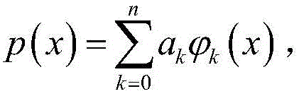
假设有n+1个线性无关连续函数:Assume there are n+1 linearly independent continuous functions:


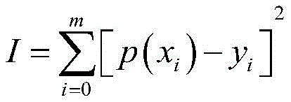
那么这组离散数据的最小二乘法拟合函数就是函数p(x);求I的最小值,由多元函数求极值的条件,得到:Then the least squares fitting function of this set of discrete data is the function p(x); find the minimum value of I, and obtain the conditions for finding the extreme value of the multivariate function:

假定记

化为范德蒙得矩阵得到:Transformed into a Vandermonde matrix, we get:

简写为:In short:
X·A=YX·A=Y
解算系数矩阵A,也就得到了多项式最小二乘法拟合曲线。By solving the coefficient matrix A, we can get the polynomial least squares fitting curve.
进一步的,所述步骤1.2的具体方法为:Furthermore, the specific method of step 1.2 is:
步骤1.2.1.将作业区域拟合为最接近的多边形,获取作业区域多边形的各顶点坐标;Step 1.2.1. Fit the working area to the closest polygon and obtain the coordinates of each vertex of the working area polygon;
步骤1.2.2.根据顶点坐标信息计算作业区域最长的一条边;Step 1.2.2. Calculate the longest side of the working area according to the vertex coordinate information;
步骤1.2.3.构建航线坐标系,基于最长边构建大地坐标系和航线坐标系;Step 1.2.3. Construct the route coordinate system, and construct the geodetic coordinate system and the route coordinate system based on the longest side;
步骤1.2.4.坐标系转换,将顶点坐标由大地坐标系中转换到航线坐标系;Step 1.2.4. Coordinate system conversion: convert the vertex coordinates from the geodetic coordinate system to the route coordinate system;
步骤1.2.5.航线规划与任务点坐标获取,坐标系建立完成后,根据实际需要规划航线;设置航线间间距与任务点间距离,在航线坐标系中平行于最长边规划无人机飞行航线并获取所有数据采集任务点航线的坐标;Step 1.2.5. Route planning and task point coordinate acquisition. After the coordinate system is established, plan the route according to actual needs; set the distance between routes and the distance between task points, plan the UAV flight route parallel to the longest side in the route coordinate system and obtain the coordinates of all data collection task point routes;
步骤1.2.6.任务队列构建,从原点开始,沿航线往返遍历所有任务点,将所有任务点的航线坐标转换为地理坐标并依次加入任务队列。Step 1.2.6. Task queue construction, starting from the origin, traverses all task points along the route, converts the route coordinates of all task points into geographic coordinates and adds them to the task queue in sequence.
进一步的,所述步骤1.4的具体方法为:Furthermore, the specific method of step 1.4 is:
步骤1.4.1.从任务队列中读取下一个目标点的大地坐标,从飞控中获取无人机初始位置的大地坐标和欧拉角数据,并将大地坐标转换到机体坐标系中;Step 1.4.1. Read the geodetic coordinates of the next target point from the task queue, obtain the geodetic coordinates and Euler angle data of the initial position of the drone from the flight control, and convert the geodetic coordinates to the body coordinate system;
步骤1.4.2.坐标系转换完成后,由初始点坐标和目标点坐标分别计算出X轴和Y轴预期移动距离Dx和Dy;Step 1.4.2. After the coordinate system conversion is completed, the expected moving distances Dx and Dy of the X-axis and Y-axis are calculated respectively from the coordinates of the initial point and the target point;
步骤1.4.3.设定容许误差d和步进量s,容许误差d表示系统允许的最大误差,当无人机位置与目标点在在X轴和Y轴两个方向的距离误差都小于d时则认为无人机抵达目标点;步进量s表示系统每次调整无人机移动的最大位移;Step 1.4.3. Set the allowable error d and step size s. The allowable error d represents the maximum error allowed by the system. When the distance error between the drone position and the target point in both the X-axis and Y-axis directions is less than d, the drone is considered to have reached the target point. The step size s represents the maximum displacement of the drone movement adjusted by the system each time.
步骤1.4.4.通过飞控获取无人机当前位置的大地坐标和欧拉角数据,并将大地坐标转换到机体坐标系中;Step 1.4.4. Obtain the geodetic coordinates and Euler angle data of the current position of the drone through the flight control, and convert the geodetic coordinates into the body coordinate system;
步骤1.4.5.通过无人机当前位置和无人机初始位置,计算无人机在X轴和Y轴两个方向已经移动的距离dx和dy,根据需要移动的距离和已经移动的距离,计算出无人机还需要移动的距离dx0和dy0;Step 1.4.5. Calculate the distance dx and dy that the drone has moved in the X-axis and Y-axis directions based on the current position of the drone and the initial position of the drone. Calculate the distance dx 0 and dy 0 that the drone needs to move based on the distance that needs to be moved and the distance that has been moved.
步骤1.4.6.判断在系统允许误差内无人机当前位置是否已经到达目标点,若是则控制方法结束,无人机在目标点上空悬停等待一下指令;若不是则继续执行下一步;Step 1.4.6. Determine whether the current position of the drone has reached the target point within the system allowable error. If so, the control method ends and the drone hovers over the target point and waits for instructions; if not, proceed to the next step;
步骤1.4.7.在X轴和Y轴两个方向上分别判断还需移动的距离是否小于步进量s,若是则下一步控制无人机在该方向移动剩余距离,若不是则控制无人机在该方向移动s距离;移动完成后回到步骤1.4.4继续执行。Step 1.4.7. Determine whether the distance to be moved in the X-axis and Y-axis directions is less than the step amount s. If so, control the drone to move the remaining distance in that direction. If not, control the drone to move s distance in that direction. After the movement is completed, return to step 1.4.4 to continue execution.
进一步的,所述步骤1.5的具体方法为:Furthermore, the specific method of step 1.5 is:
步骤1.5.1.下降第一阶段,第一阶段根据无人机自身GPS数据和气压计高度数据,控制无人机快速下降到h1高度;Step 1.5.1. The first stage of descent: In the first stage, the drone is controlled to descend rapidly to a height of h 1 based on its own GPS data and barometer altitude data;
步骤1.5.2.下降第二阶段,第二阶段主要依据系统定高模块实时测得的当前测距传感器与地面的高度信息控制无人机缓慢下降到h2高度,h2为系统的数据采集作业高度。Step 1.5.2. The second stage of descent. The second stage mainly controls the drone to slowly descend to h2 height based on the height information between the current ranging sensor and the ground measured in real time by the system's altitude determination module. h2 is the data collection operating height of the system.
进一步的,所述步骤1.2.5的具体方法为:Furthermore, the specific method of step 1.2.5 is:
航线规划与任务点坐标获取,坐标系建立完成后,就可以根据实际需要规划航线;设置航线间间距与任务点间距离,在航线坐标系中平行于最长边规划无人机飞行航线并获取所有数据采集任务点航线的坐标;Route planning and task point coordinate acquisition: After the coordinate system is established, the route can be planned according to actual needs; the distance between routes and the distance between task points can be set, and the flight route of the drone can be planned parallel to the longest side in the route coordinate system and the coordinates of all data collection task point routes can be obtained;
计算步骤1.2.1中拟合的多边形m个顶点中最大的y轴坐标ymax=max(yV1,yV2,…,yVn),设定两条相邻航线的距离D,在y=0到y=ymax之间作距离为D且平行于yV1yV2的一组直线;在XOY中,通过计算步骤1.2.1中拟合的多边形与该组直线的交点,保留多边形内部的航线得到了最后的无人机作业航线;规划好航线后,确定一条航线中两个相邻任务点之间的距离d,遍历每一条航线,由公式(3)确定每条航线的任务点数,将这些任务点均匀分布在航线上;Calculate the maximum y-axis coordinate y max = max(y V1 ,y V2 ,…,y Vn ) of the m vertices of the polygon fitted in step 1.2.1, set the distance D between two adjacent routes, and draw a set of straight lines with a distance D between y = 0 and y = y max and parallel to y V1 y V2 ; in XOY, by calculating the intersection of the polygon fitted in step 1.2.1 and the set of straight lines, retain the route inside the polygon to obtain the final UAV operation route; after planning the route, determine the distance d between two adjacent task points in a route, traverse each route, determine the number of task points for each route by formula (3), and evenly distribute these task points on the route;

式中,ni表示第i条航线上的任务点数目,rund表示四舍五入取整,xi2和xi1分别是航线右侧端点和左侧端点的X轴坐标。Where ni represents the number of mission points on the ith route, rund represents rounding to the nearest integer, xi2 and xi1 are the X-axis coordinates of the right and left endpoints of the route, respectively.
进一步的,所述步骤1.5.1的具体方法为:Furthermore, the specific method of step 1.5.1 is:
S1:读取h1、h2、高度容许误差h以及翻滚角容许误差r信息;S1: Read h 1 , h 2 , height tolerance h and roll angle tolerance r information;
S2:获取无人机当前位置的大地坐标和欧拉角数据,并将大地坐标转换到机体坐标系中;S2: Obtain the geodetic coordinates and Euler angle data of the current position of the drone, and convert the geodetic coordinates into the body coordinate system;
S3:通过无人机当前高度和h2计算预期位移:Z1=H-h2;S3: Calculate the expected displacement using the current altitude of the drone and h 2 : Z 1 =Hh 2 ;
S4:系统再次获取无人机当前位置的大地坐标和欧拉角数据,并将大地坐标转换到机体坐标系中;S4: The system obtains the geodetic coordinates and Euler angle data of the current position of the UAV again, and converts the geodetic coordinates into the body coordinate system;
S5:系统根据无人机当前翻滚角对翻滚角进行反向调整;S5: The system adjusts the roll angle in the opposite direction according to the current roll angle of the drone;
S6:通过无人机当前高度计算确定剩余的位移量:Z2=hnow-h2,其中hnow为当前无人机的高度;S6: Calculate and determine the remaining displacement according to the current altitude of the UAV: Z 2 =h now -h 2 , where h now is the current altitude of the UAV;
S7:判断剩余的位移量是否都小于容许误差h或者为负数,如是,则进入S10,否则进入步骤步骤S8继续执行;S7: Determine whether the remaining displacements are all less than the allowable error h or are negative numbers. If so, proceed to S10; otherwise, proceed to step S8 to continue execution;
S8:判断剩余的位移量是否小于设定步进量,若是则下降z高度,否则下降最大步进量;S8: Determine whether the remaining displacement is less than the set step amount, if so, decrease the z height, otherwise decrease the maximum step amount;
S9:从新计算剩余的位移量,根据上一步下降的高度不同,z为0或Z2-s,并再次执行步骤步骤S8;S9: recalculate the remaining displacement, z is 0 or Z 2 -s according to the height of the previous step, and execute step S8 again;
S10:判断当前翻滚角的绝对值是否在系统容许误差范围内,若是则完成第一阶段控制进入第二阶段,否则执行步骤步骤S4。S10: Determine whether the absolute value of the current roll angle is within the system allowable error range. If so, complete the first stage control and enter the second stage. Otherwise, execute step S4.
进一步的,所述步骤1.5.2的具体方法为:Furthermore, the specific method of step 1.5.2 is:
D1:获取实时高度数据,判断高度数据与作业高度之间差的绝对值是否满足系统容许误差,如是则等待后续数据采集,否则继续执行;D1: Get real-time height data and determine whether the absolute value of the difference between the height data and the working height meets the system tolerance. If yes, wait for subsequent data collection, otherwise continue to execute;
D2:求0.05m和高度数据与作业高度之间差的绝对值的0.7倍两个数据中小的值,然后控制无人机向下移动这个较小值的距离,完成后执行步骤D1。D2: Calculate the smaller value of the two data: 0.05m and 0.7 times the absolute value of the difference between the height data and the operating height, and then control the drone to move downward by the smaller value. After completion, execute step D1.
本发明利用嵌入式设备等,针对具体应用场景研究实现无人机的专用控制监测系统,进一步扩大了无人机的实际应用能力;本发明将无人机技术与XRF技术进行结合,同时综合嵌入式设备、便携式设备及多种传感器等硬件,以及电子技术、计算机技术等,多学科交叉融合,为其它如环境监测等专业领域所遇到困境的解决具有重要参考价值;本发明针对我国土壤重金属污染严峻态势及实际应用需求,研制一种土壤重金属污染快速检测软硬件系统设备,弥补了现有技术的不足,为土壤重金属污染检测实际应用中面临的困境提供新的完整解决方案。The present invention utilizes embedded devices, etc., and studies and implements a dedicated control and monitoring system for drones for specific application scenarios, thereby further expanding the practical application capabilities of drones; the present invention combines drone technology with XRF technology, and integrates hardware such as embedded devices, portable devices, and various sensors, as well as electronic technology, computer technology, etc., to achieve multidisciplinary cross-integration, which has important reference value for solving difficulties encountered in other professional fields such as environmental monitoring; the present invention develops a soil heavy metal pollution rapid detection software and hardware system equipment in response to the severe situation of soil heavy metal pollution in my country and the actual application needs, which makes up for the shortcomings of the existing technology and provides a new and complete solution to the difficulties faced in the actual application of soil heavy metal pollution detection.
附图说明BRIEF DESCRIPTION OF THE DRAWINGS
图1为本发明总体技术路线图。FIG. 1 is an overall technical roadmap of the present invention.
图2为本发明整体硬件结构图。FIG. 2 is a diagram showing the overall hardware structure of the present invention.
图3为本发明无人机协同控制与自动飞行系统总体流程示意图。FIG3 is a schematic diagram of the overall flow of the UAV cooperative control and automatic flight system of the present invention.
图4为本发明航线规划与任务队列构建流程图。FIG4 is a flow chart of route planning and task queue construction according to the present invention.
图5为本发明航线及任务点示意图。FIG5 is a schematic diagram of the route and mission points of the present invention.
图6为本发明无人机平面飞行控制算法流程图。FIG6 is a flow chart of the UAV planar flight control algorithm of the present invention.
图7为本发明无人机下降过程控制算法流程图。FIG. 7 is a flow chart of the control algorithm for the descent process of the UAV of the present invention.
图8为本发明数据采集驱动装置示意图;(a)为释放状态,(b)为驱动状态。FIG8 is a schematic diagram of the data acquisition driving device of the present invention; (a) is a released state, and (b) is a driven state.
图9为本发明一次数据采集过程示意图。FIG. 9 is a schematic diagram of a data collection process of the present invention.
具体实施方式DETAILED DESCRIPTION
为使本发明的目的、技术方案和优点更加清楚,下面结合实施方式和附图,对本发明作进一步地详细描述。In order to make the objectives, technical solutions and advantages of the present invention more clear, the present invention is further described in detail below in conjunction with the implementation modes and the accompanying drawings.
本发明最终实现一套软硬件协同的无人机机载XRF土壤重金属污染快速检测系统,该系统能够实现无人机飞行任务规划、飞行高度及速度等自动控制和飞行状态实时监测等功能;能够实现便携式XRF分析仪在一定距离下自动准确检测土壤内重金属含量的功能;最终实现区域化、快速化和便捷化的土壤重金属污染检测的功能,为当前土壤重金属污染检测实际应用中遇到的困境提供新的解决方案。本发明的总体技术路线如图1所示。The present invention finally realizes a set of software and hardware coordinated UAV airborne XRF soil heavy metal pollution rapid detection system, which can realize the functions of UAV flight mission planning, automatic control of flight altitude and speed, and real-time monitoring of flight status; it can realize the function of portable XRF analyzer to automatically and accurately detect the heavy metal content in soil at a certain distance; it finally realizes the function of regionalized, rapid and convenient soil heavy metal pollution detection, and provides a new solution to the difficulties encountered in the current practical application of soil heavy metal pollution detection. The overall technical route of the present invention is shown in Figure 1.
该技术路线按照硬件可主要分为地面控制端、飞行平台、系统中心、连接驱动模块及数据采集器等五大子系统。This technical route can be mainly divided into five subsystems according to the hardware, namely the ground control terminal, flight platform, system center, connection drive module and data acquisition device.
(1)地面控制端:用户与系统的交互窗口,用户通过电脑等设备规划提交任务并实时监测无人机的飞行状态,可以随时通过指令或无人机遥控器控制无人机的飞行,另一方面也接收嵌入式设备处理后的最终检测结果并向用户展示。(1) Ground control terminal: The interactive window between the user and the system. The user plans and submits tasks through computers and other devices and monitors the flight status of the UAV in real time. The user can control the flight of the UAV at any time through instructions or the UAV remote control. On the other hand, the user also receives the final detection results processed by the embedded device and displays them to the user.
(2)飞行平台:无人机及其附属连接装置等设备构成系统的负载和飞行平台,无人机飞控主要负责与嵌入式设备及便携式设备进行通信,按规划好的任务、无人机遥控和嵌入式设备的控制指令控制无人机的飞行。(2) Flight platform: The UAV and its associated connection devices constitute the system's load and flight platform. The UAV flight control is mainly responsible for communicating with embedded devices and portable devices, and controlling the flight of the UAV according to the planned tasks, UAV remote control, and control instructions from embedded devices.
(3)系统中心:嵌入式设备是整个系统的控制与数据处理中心,主要有两个功能:其一为控制中心,根据接收到的各方面信息综合判断系统当前状态,并向XRF连接驱动模块和无人机进行及时恰当的控制指令发送。其二为数据中心,接收XRF采集到的数据,并对数据进行必要的反演得到金属含量信息,将检测结果保存在本地的同时发送给便携式设备进行展示。(3) System Center: The embedded device is the control and data processing center of the entire system, and has two main functions: the first is the control center, which comprehensively judges the current state of the system based on the information received from various aspects, and sends timely and appropriate control instructions to the XRF connection drive module and the drone. The second is the data center, which receives the data collected by XRF, performs necessary inversion on the data to obtain metal content information, and saves the test results locally and sends them to portable devices for display.
(4)连接驱动模块:主要是将无人机平台与便携式XRF分析仪连接起来,并代替人手实现XRF分析仪的数据采集的自动驱动;(4) Connection drive module: mainly connects the UAV platform with the portable XRF analyzer and automatically drives the XRF analyzer to collect data instead of manual operation;
(5)数据采集器:便携式XRF分析仪是系统的数据采集器,它受数据采集驱动装置的控制进行数据采集,并将采集到的荧光数据发送到嵌入式设备进一步处理。(5) Data collector: The portable XRF analyzer is the data collector of the system. It is controlled by the data acquisition driver to collect data and send the collected fluorescence data to the embedded device for further processing.
一个完整的任务实施流程如下:用户输入任务区域坐标,系统首先规划任务航线构建任务队列,,无人机按照任务飞行到第一个任务点上空,控制中心通过任务点数据和GPS数据等信息判断无人机到达任务点,随及发送指令控制无人机下降,并通过无人机速度、高度、GPS数据及定高模块数据等实时信息确定无人机降至指定高度时控制无人机悬停,同时发送指令控制XRF分析仪进行数据采集,当数据采集完毕后,控制中心控制无人机上升高度并飞入下一个任务点,同时数据中心对数据进行反演处理。重复上述过程直到整个任务完成并返航。A complete task implementation process is as follows: the user inputs the coordinates of the task area, the system first plans the task route and builds a task queue, the drone flies to the first task point according to the task, the control center determines that the drone has arrived at the task point through information such as the task point data and GPS data, and then sends a command to control the drone to descend, and determines that the drone controls the drone to hover when it drops to the specified height through real-time information such as the drone speed, altitude, GPS data and height-fixing module data, and sends a command to control the XRF analyzer to collect data. When the data collection is completed, the control center controls the drone to rise and fly to the next task point, and the data center performs inversion processing on the data. Repeat the above process until the entire task is completed and returns.
从图2中可以看出本发明硬件根据不同功能可以从总体上分为三个部分,分别是以嵌入式开发板为主的系统中心、以无人机为主的系统飞行平台和以便携式XRF分析仪为主的数据采集器。系统中无人机和便携式XRF分析仪通过连接装置连接;嵌入式开发板通过USB-UART与无人机进行数据通信,通过UART通信协议获取当前无人机的精确高度信息并向无人机飞控发送飞行指令,通过TTL(Transistor-Transistor Logic,晶体管-晶体管逻辑电平)信号控制数据采集驱动装置进行数据获取,同样通过TTL信号获取精确定高模块和触地监测模块的数据;便携式XRF分析仪通过Micro-USB数据线将采集到的数据发送给嵌入式开发板;地面端操作人员利用笔记本电脑通过无线网络与嵌入式开发板连接通信,从而控制整个系统。It can be seen from FIG2 that the hardware of the present invention can be generally divided into three parts according to different functions, namely, the system center mainly based on the embedded development board, the system flight platform mainly based on the unmanned aerial vehicle, and the data collector mainly based on the portable XRF analyzer. In the system, the unmanned aerial vehicle and the portable XRF analyzer are connected through a connecting device; the embedded development board communicates data with the unmanned aerial vehicle through USB-UART, obtains the precise height information of the current unmanned aerial vehicle through the UART communication protocol and sends flight instructions to the unmanned aerial vehicle flight control, controls the data acquisition drive device to acquire data through TTL (Transistor-Transistor Logic, transistor-transistor logic level) signals, and also acquires data from the precise height determination module and the ground contact monitoring module through TTL signals; the portable XRF analyzer sends the collected data to the embedded development board through the Micro-USB data cable; the ground operator uses a laptop computer to communicate with the embedded development board through a wireless network, thereby controlling the entire system.
从图1中可以看出本发明软件包括无人机协同控制与自动飞行系统、XRF数据自动采集系统和重金属含量反演处理系统。It can be seen from FIG. 1 that the software of the present invention includes a UAV cooperative control and automatic flight system, an XRF data automatic acquisition system, and a heavy metal content inversion processing system.
无人机自动飞行控制模块:根据检测区域规划作业航线和任务点,在此基础上实现控制搭载其它硬件设备的无人机按照预定航线和轨迹进行飞行作业,配合其它软硬件模块完成数据采集任务;UAV automatic flight control module: plans the operation route and task points according to the detection area, and on this basis controls the UAV equipped with other hardware equipment to perform flight operations according to the predetermined route and trajectory, and cooperates with other software and hardware modules to complete the data collection task;
传感器硬件数据获取分析模块,包括实现定高模块数据获取和触地监测模块数据获取分析功能,辅助无人机自动飞行控制模块实现无人机精准稳定安全的作业飞行;The sensor hardware data acquisition and analysis module, including the data acquisition and analysis functions of the altitude determination module and the ground contact monitoring module, assists the UAV automatic flight control module to achieve accurate, stable and safe flight operations of the UAV;
数据采集处理模块:负责控制数据采集驱动装置实现数据采集过程的自动控制,以及构建土壤中重金属元素的反演模型,根据系统近地采集到的原始数据得到土壤中重金属元素准确含量。Data acquisition and processing module: responsible for controlling the data acquisition drive device to realize automatic control of the data acquisition process, and building an inversion model for heavy metal elements in the soil, and obtaining the accurate content of heavy metal elements in the soil based on the original data collected by the system near the ground.
系统软件平台中的三个模块并不是孤立存在的,它们相对独立但又相互联系,共同在硬件平台的基础上实现无人机机载XRF土壤重金属污染快速检测。The three modules in the system software platform do not exist in isolation. They are relatively independent but interconnected, and together they realize the rapid detection of soil heavy metal pollution by drone-borne XRF based on the hardware platform.
所述无人机协同控制与自动飞行系统,总体流程如图3所示,包括以下步骤:The overall process of the UAV cooperative control and automatic flight system is shown in FIG3 and includes the following steps:
步骤1.系统各个模块初始化以及自检,保证系统各模块工作正常;Step 1. Initialize and self-check each module of the system to ensure that each module of the system works normally;
系统首先会对开发板与无人机通信模块、定高模块、触地检测模块和驱动控制装置等部分进行自检,只有当这些模块的软硬件都能工作正常时才会进入下一步;接着会启动无人机自检程序,保证无人机当前状态下能够正常飞行The system will first perform a self-check on the development board and the drone communication module, altitude control module, ground detection module, and drive control device. Only when the software and hardware of these modules are working properly will it proceed to the next step; then it will start the drone self-check program to ensure that the drone can fly normally in the current state.
步骤2.规划土壤重金属污染监测的无人机飞行任务航线,并构建任务队列,为了尽量减少作业过程中无人机更改航线航向的次数,系统采用航线平行最长边的方法规划航线,流程如图3所示,具体处理过程如下:Step 2. Plan the flight mission route of the drone for soil heavy metal pollution monitoring and build a task queue. In order to minimize the number of times the drone changes its route and heading during the operation, the system plans the route by using the method of parallel longest side. The process is shown in Figure 3. The specific processing process is as follows:
步骤2.1.获取作业区域多边形的顶点坐标;Step 2.1. Obtain the vertex coordinates of the working area polygon;
步骤2.2.寻找多边形最长边,根据坐标信息计算作业区域最长的一条边;Step 2.2. Find the longest side of the polygon and calculate the longest side of the working area based on the coordinate information;
步骤2.3.构建航线坐标系,基于最长边构建大地坐标系和航线坐标系;Step 2.3. Construct the route coordinate system, and construct the geodetic coordinate system and the route coordinate system based on the longest side;
在一个拥有m个顶点的凸多边形中,最长的边假设为V1V2(其中的顶点V1在顶点V2的西边),以顶点V1为原点,正东和正北方向为Xn轴和Yn轴建立大地坐标系XnOYn,将大地坐标系绕原点旋转θ角使得OXn与V1V2重合,得到新的航线坐标系XOY。In a convex polygon with m vertices, the longest side is assumed to be V 1 V 2 (vertex V 1 is west of vertex V 2 ). Take vertex V 1 as the origin and the east and north directions as the Xn and Yn axes to establish a geodetic coordinate system XnOYn. Rotate the geodetic coordinate system around the origin by an angle θ so that OXn coincides with V 1 V 2 , and obtain a new route coordinate system XOY.
步骤2.4.坐标系转换,将顶点坐标由大地坐标系中转换到航线坐标系;Step 2.4. Coordinate system conversion: convert the vertex coordinates from the geodetic coordinate system to the route coordinate system;
在一个检测区域内,区域各个顶点都在东半球且它们之间的经纬度差异很小,地球曲率的影响可以忽略不计,将顶点坐标由大地坐标系中转换到航线坐标系中的公式为。In a detection area, all vertices of the area are in the Eastern Hemisphere and the differences in longitude and latitude between them are very small. The influence of the earth's curvature can be ignored. The formula for converting the vertex coordinates from the geodetic coordinate system to the route coordinate system is:

式中,x、y为顶点在航线坐标系中的坐标,单位为米;xn、yn为顶点的地理坐标中的经度和维度,单位为度;Rc、Rj分别为地球赤道半径和极半径,取Rc=6378137m,Rj=6356725m;圆周率π取3.14159265;θ是坐标系旋转的角度,可以通过公式(2)计算。Where x and y are the coordinates of the vertex in the route coordinate system, in meters; xn and yn are the longitude and latitude of the vertex in the geographic coordinates, in degrees; R c and R j are the equatorial radius and polar radius of the earth, respectively, R c = 6378137m and R j = 6356725m; pi is 3.14159265; θ is the angle of rotation of the coordinate system, which can be calculated by formula (2).

步骤2.5.航线规划与任务点坐标获取,坐标系建立完成后,就可以根据实际需要规划航线。设置航线间间距与任务点间距离,在航线坐标系中平行于最长边规划无人机飞行航线并获取所有数据采集任务点航线的坐标,如图4所示;Step 2.5. Route planning and task point coordinate acquisition. After the coordinate system is established, the route can be planned according to actual needs. Set the distance between routes and the distance between task points, plan the UAV flight route parallel to the longest side in the route coordinate system and obtain the coordinates of all data collection task point routes, as shown in Figure 4;
计算m个顶点中最大的y轴坐标ymax=max(yV1,yV2,…,yVn),输入参数D表示两条相邻航线的距离,在y=0到y=ymax之间作距离为D且平行于yV1yV2的一组直线。在XOY中,多边形任意一条边AiAi+1,i∈(1,2,…,m-1)都可以计算,通过计算这些平行线与多边形边的交点,保留多边形内部的航线就得到了最后的无人机作业航线。规划好航线后,输入参数d表示一条航线中两个相邻任务点之间的距离,遍历每一条航线,由公式(3)确定每条航线的任务点数,将这些任务点均匀分布在航线上。Calculate the maximum y-axis coordinate y max = max(y V1 ,y V2 ,…,y Vn ) among the m vertices. Input parameter D represents the distance between two adjacent routes. Draw a set of straight lines parallel to y V1 y V2 with a distance of D between y = 0 and y = y max . In XOY, any edge of the polygon A i A i+1 ,i∈(1,2,…,m-1) can be calculated. By calculating the intersection of these parallel lines with the polygon edge and retaining the route inside the polygon, the final UAV operation route is obtained. After planning the route, input parameter d represents the distance between two adjacent task points in a route. Traverse each route and determine the number of task points for each route by formula (3). Distribute these task points evenly on the route.

式中,ni表示第i条航线上的任务点数目,rund表示四舍五入取整,xi2和xi1分别是航线右侧端点和左侧端点的X轴坐标。Where ni represents the number of mission points on the ith route, rund represents rounding to the nearest integer, xi2 and xi1 are the X-axis coordinates of the right and left endpoints of the route, respectively.
步骤2.6.任务队列构建,从原点开始,沿航线往返遍历所有任务点,将所有任务点的航线坐标转换为地理坐标并依次加入任务队列,得到在参数D和l控制下的作业任务队列。公式(4)是任务点坐标转换为地理坐标的方法。Step 2.6. Task queue construction, starting from the origin, traverse all task points along the route, convert the route coordinates of all task points into geographic coordinates and add them to the task queue in sequence, and obtain the job task queue under the control of parameters D and l. Formula (4) is the method for converting task point coordinates into geographic coordinates.

步骤3.无人机起飞,当任务队列有效时,无人机起飞到指定高度H,H为设定的无人机平面飞行高度;Step 3. The drone takes off. When the task queue is valid, the drone takes off to the specified height H, where H is the set flight height of the drone.
步骤4.无人机平面飞行自动控制,控制无人机飞行到下一个任务点上空。无人机在作业平面飞行路径中是一个由A点到B点的直线,高度保持为飞行高度H不变,无人机平面飞行过程中不考虑高度的控制,主要针对机体坐标系中控制无人机在X轴和Y轴的移动,无人机平面飞行控制算法如图5所示,具体过程为:Step 4. Automatically control the plane flight of the UAV, and control the UAV to fly to the next mission point. The plane flight path of the UAV is a straight line from point A to point B, and the height remains unchanged at the flight height H. The height control is not considered during the plane flight of the UAV, and the main focus is on controlling the movement of the UAV on the X-axis and Y-axis in the body coordinate system. The plane flight control algorithm of the UAV is shown in Figure 5. The specific process is:
步骤4.1.从任务队列中读取下一个目标点的大地坐标,从飞控中获取无人机初始位置的大地坐标和欧拉角数据,并将大地坐标转换到机体坐标系中;Step 4.1. Read the geodetic coordinates of the next target point from the task queue, obtain the geodetic coordinates and Euler angle data of the initial position of the drone from the flight control, and convert the geodetic coordinates to the body coordinate system;
步骤4.2.坐标系转换完成后,由初始点坐标和目标点坐标可以分别计算出X轴和Y轴预期移动距离Dx和Dy;Step 4.2. After the coordinate system conversion is completed, the expected moving distances Dx and Dy of the X-axis and Y-axis can be calculated respectively from the coordinates of the initial point and the target point;
步骤4.3.系统读取预先设定好的容许误差d和步进量s,容许误差d表示系统允许的最大误差,当无人机位置与目标点在在X轴和Y轴两个方向的距离误差都小于d时则认为无人机抵达目标点;步进量s表示系统每次调整无人机移动的最大位移;Step 4.3. The system reads the preset allowable error d and step size s. The allowable error d indicates the maximum error allowed by the system. When the distance error between the drone position and the target point in both the X-axis and Y-axis directions is less than d, the drone is considered to have reached the target point. The step size s indicates the maximum displacement of the drone movement adjusted by the system each time.
步骤4.4.系统通过飞控获取无人机当前位置的大地坐标和欧拉角数据,并将大地坐标转换到机体坐标系中;Step 4.4. The system obtains the geodetic coordinates and Euler angle data of the current position of the drone through the flight control, and converts the geodetic coordinates into the body coordinate system;
步骤4.5.通过无人机当前位置和无人机初始位置,计算无人机在X轴和Y轴两个方向已经移动的距离dx和dy,通过公式(5)可以计算出无人机还需要移动的距离dx0和dy0;Step 4.5. Calculate the distance dx and dy that the drone has moved in the X-axis and Y-axis directions by using the current position of the drone and the initial position of the drone. The distance dx 0 and dy 0 that the drone needs to move can be calculated by using formula (5);

步骤4.6.判断在系统允许误差内无人机当前位置是否已经到达目标点,若是则控制算法结束,无人机在目标点上空悬停等待一下指令;若不是则继续执行下一步;Step 4.6. Determine whether the current position of the drone has reached the target point within the system allowable error. If so, the control algorithm ends and the drone hovers over the target point and waits for instructions; if not, proceed to the next step;
步骤4.7.在X轴和Y轴两个方向上分别判断还需移动的距离是否小于步进量s,若是则下一步控制无人机在该方向移动剩余距离,若不是则控制无人机在该方向移动s距离;移动完成后回到步骤4.4继续执行。Step 4.7. Determine whether the distance to be moved in the X-axis and Y-axis directions is less than the step amount s. If so, control the drone to move the remaining distance in that direction. If not, control the drone to move s distance in that direction. After the movement is completed, return to step 4.4 to continue execution.
步骤5.无人机下降过程自动控制,为了采集到有效的数据,需要控制无人机下降到预定高度悬停,并完成数据采集。无人机下降分为两个阶段,无人机下降过程控制算法如图6所示,具体过程如下:Step 5. Automatic control of the drone's descent process. In order to collect valid data, the drone needs to be controlled to descend to a predetermined height and hover, and complete data collection. The drone's descent is divided into two stages. The drone's descent process control algorithm is shown in Figure 6. The specific process is as follows:
步骤5.1.下降第一阶段,第一阶段根据无人机自身GPS数据和气压计高度数据,控制无人机快速下降到h1高度;Step 5.1. The first stage of descent: In the first stage, the drone is controlled to descend rapidly to a height of h 1 based on its own GPS data and barometer altitude data;
第一个阶段无人机由飞行高度H下降到高度h1,h1根据实际情况选择1到2m,这个阶段无人机下降不容易受到地面地物及人员的影响,系统整体比较安全,因此这个阶段主要在无人机自身GPS数据辅助下实现无人机下降控制,同时为保证数据采集时便携式XRF分析仪的探头垂直地面,这个阶段还对飞机的翻滚角roll进行控制,具体过程如下:In the first stage, the drone descends from the flight altitude H to the altitude h 1 . The altitude h 1 is selected from 1 to 2 meters according to the actual situation. In this stage, the drone is not easily affected by ground objects and personnel, and the system is relatively safe. Therefore, in this stage, the drone descent control is mainly achieved with the assistance of the drone's own GPS data. At the same time, in order to ensure that the probe of the portable XRF analyzer is vertical to the ground during data collection, the roll angle of the aircraft is also controlled in this stage. The specific process is as follows:
步骤5.1.1系统读取h1、h2、高度容许误差h以及翻滚角容许误差r等信息;Step 5.1.1 The system reads h 1 , h 2 , height tolerance h, and roll angle tolerance r;
步骤5.1.2.系统通过飞控获取无人机当前位置的大地坐标和欧拉角数据,并将大地坐标转换到机体坐标系中;Step 5.1.2. The system obtains the geodetic coordinates and Euler angle data of the current position of the drone through the flight control, and converts the geodetic coordinates into the body coordinate system;
步骤5.1.3.通过无人机当前高度和h2计算预期位移:Z1=H-h2;Step 5.1.3. Calculate the expected displacement using the current altitude of the drone and h 2 : Z 1 =Hh 2 ;
步骤5.1.4.系统再次通过飞控获取无人机当前位置的大地坐标和欧拉角数据,并将大地坐标转换到机体坐标系中;Step 5.1.4. The system obtains the geodetic coordinates and Euler angle data of the current position of the drone through the flight control again, and converts the geodetic coordinates into the body coordinate system;
步骤5.1.5.系统将以当前无人机翻滚角0.6倍的值对翻滚角进行反向调整;Step 5.1.5. The system will adjust the roll angle in the opposite direction by 0.6 times the current roll angle of the drone;
步骤5.1.6.通过无人机当前高度计算确定剩余的位移量:Z2=hnow-h2,其中hnow为当前无人机的高度;Step 5.1.6. Determine the remaining displacement by calculating the current altitude of the drone: Z 2 = h now -h 2 , where h now is the current altitude of the drone;
步骤5.1.7.判断剩余的位移量是都小于容许误差h或者为负数,如是则进入步骤(10)继续执行,否则进入步骤步骤5.1.8继续执行;Step 5.1.7. Determine whether the remaining displacement is less than the allowable error h or is a negative number. If so, proceed to step (10) to continue execution. Otherwise, proceed to step 5.1.8 to continue execution.
步骤5.1.8.判断剩余的位移量是否小于0.1m,若是则下降z高度,否则下降最大步进量0.1m;Step 5.1.8. Determine whether the remaining displacement is less than 0.1m. If so, lower the z height. Otherwise, lower the maximum step size by 0.1m.
步骤5.1.9.从新计算剩余的位移量,根据上一步下降的高度不同,z为0或Z2-0.1,并再次执行步骤步骤5.1.8;Step 5.1.9. Recalculate the remaining displacement, z is 0 or Z 2 -0.1 according to the height of the previous step, and execute step 5.1.8 again;
步骤5.1.10.判断当前翻滚角的绝对值是否在系统容许误差范围内,若是则完成第一阶段控制进入第二阶段,否则执行步骤步骤5.1.4。Step 5.1.10. Determine whether the absolute value of the current roll angle is within the system allowable error range. If so, complete the first stage control and enter the second stage. Otherwise, execute step 5.1.4.
步骤5.2.下降第二阶段,第二阶段主要依据系统定高模块实时测得的当前测距传感器与地面的高度信息控制无人机缓慢下降到h2高度,h2也就是系统的数据采集作业高度;无人机下降过程第二阶段是实现数据采集的重要一步,这一阶段的无人机控制保持安全谨慎的态度,具体过程如下:Step 5.2. The second stage of descent. The second stage mainly controls the drone to slowly descend to h2 height based on the height information between the current ranging sensor and the ground measured in real time by the system's altitude determination module. h2 is the data collection operation height of the system. The second stage of the drone descent process is an important step in realizing data collection. The drone control at this stage maintains a safe and cautious attitude. The specific process is as follows:
步骤5.2.1获取定高模块数据,判断定高模块数据与作业高度之间差的绝对值是否满足系统容许误差,如是则等待后续数据采集,否则继续执行;Step 5.2.1: Get the height determination module data, and determine whether the absolute value of the difference between the height determination module data and the working height meets the system tolerance. If yes, wait for subsequent data collection, otherwise continue to execute;
步骤5.2.2.求0.05m和高模块数据与作业高度之间差的绝对值的0.7倍两个数据中小的值,然后控制无人机向下移动这个较小值的距离,完成后执行步骤5.2.1。Step 5.2.2. Calculate the smaller value of the two data: 0.05m and 0.7 times the absolute value of the difference between the high module data and the operating height, and then control the drone to move downward by the smaller distance. After completion, execute step 5.2.1.
步骤6.无人机悬停以及数据采集,无人机保持h2高度精确悬停直到数据采集完成。重复步骤4直到任务队列中所有任务点均完成数据采集工作;Step 6. The drone hovers and collects data. The drone maintains precise hovering at a height of h 2 until data collection is completed. Repeat step 4 until all task points in the task queue have completed data collection;
步骤7.无人机返航降落,自动控制无人机返航到起飞点坐标上空并降落。Step 7. The drone returns and lands. The drone is automatically controlled to return to the take-off point coordinates and land.
所述XRF数据自动采集系统:The XRF data automatic acquisition system:
便携式XRF分析仪采集数据时,需要扣动机身的扳机才能启动数据采集功能,因此为了实现自动采集数据的功能,本发明设计实现了代替人手扣动扳机的数据采集驱动装置,驱动装置在开发板的控制信号控制下,其驱动结构能够模拟人手对便携式XRF分析仪的扳机进行控制,图8为扳机释放与驱动示意图。包括以下步骤:When the portable XRF analyzer collects data, it is necessary to pull the trigger of the body to start the data collection function. Therefore, in order to realize the function of automatic data collection, the present invention designs and implements a data collection driving device that replaces manual triggering. Under the control of the control signal of the development board, the driving structure of the driving device can simulate the human hand to control the trigger of the portable XRF analyzer. Figure 8 is a schematic diagram of trigger release and driving. It includes the following steps:
步骤1.初始化嵌入式设备GPIO(General Purpose I/O Ports,通用输入/输出端口)环境;Step 1. Initialize the embedded device GPIO (General Purpose I/O Ports) environment;
由于需要用到GPIO引脚进行IO通信,需要初始化Raspberry Pi的GPIO引脚;Since GPIO pins are needed for IO communication, the GPIO pins of Raspberry Pi need to be initialized;
步骤2.定义引脚模式;Step 2. Define the pin mode;
根据电路连接图,定义相应的引脚编号并全部设置为输出模式;According to the circuit connection diagram, define the corresponding pin numbers and set them all to output mode;
步骤3.嵌入式设备输出控制信号,开始数据采集;Step 3. The embedded device outputs a control signal and starts data collection;
对于直流电磁铁,信号IN为高电平时电磁铁通电,扳机被扣动,否则扳机处于释放状态;对于电动推杆,当EN、IN1和IN2信号均为高电平时推杆伸出,扳机被释放,当只有IN1为低电平时推杆缩回,扳机被扣动,当三个信号全为低电平时推杆静止不动。For a DC electromagnet, when the signal IN is at a high level, the electromagnet is energized and the trigger is pulled, otherwise the trigger is in a released state; for an electric push rod, when the EN, IN1 and IN2 signals are all at high levels, the push rod extends and the trigger is released; when only IN1 is at a low level, the push rod retracts and the trigger is pulled; when all three signals are at low levels, the push rod remains stationary.
步骤4.数据采集,便携式XRF分析仪开始采集数据并记录存储该点土壤内重金属元素种类及含量等数据;Step 4. Data collection: the portable XRF analyzer starts to collect data and records and stores data such as the type and content of heavy metal elements in the soil at that point;
所述重金属含量反演处理系统:The heavy metal content inversion processing system:
无人机机载XRF土壤重金属污染快速检测系统受限于地面复杂环境,为保证系统安全,在进行数据采集时便携式XRF分析仪不能够进行贴地检测而是采取了近地检测的方法,检测距离增加导致采集到的X荧光量减少,因此便携式XRF分析仪自身数据处理系统针对贴地检测所构建的校正曲线失效,系统需要重建合适的模型曲线,将近地检测得到的重金属元素含量数据反演为贴地检测时测得重金属元素含量数据。本发明基于线性最小二乘法拟合,得到近地检测数据到贴地检测数据的线性拟合函数,通过拟合函数实现数据反演。包括以下步骤:The UAV-mounted XRF soil heavy metal pollution rapid detection system is limited by the complex ground environment. To ensure the safety of the system, the portable XRF analyzer cannot perform ground detection during data collection, but adopts a near-ground detection method. The increase in detection distance leads to a decrease in the amount of X-ray fluorescence collected. Therefore, the correction curve constructed by the portable XRF analyzer's own data processing system for ground detection is invalid. The system needs to rebuild a suitable model curve to invert the heavy metal element content data obtained by near-ground detection into the heavy metal element content data measured during ground detection. The present invention is based on linear least squares fitting to obtain a linear fitting function from near-ground detection data to ground detection data, and data inversion is achieved through the fitting function. The following steps are included:
步骤1.数据采集,在待检测区域内均匀选择足够的采样点,每个样点分别近地检测和贴地检测获取一组待测金属元素含量数据;Step 1. Data collection: select enough sampling points evenly in the area to be tested, and perform near-ground and close-ground testing on each sampling point to obtain a set of data on the content of the metal element to be tested;
步骤2.数据检查与数据预处理,数据采集完成后,通过由已知数据画出散点图等方式进行数据检查,将明显错误的数据剔除,根据初略图像初步确定多项式的拟合次数m;Step 2. Data inspection and data preprocessing: After data collection is completed, data inspection is performed by drawing a scatter plot from known data, and obviously erroneous data is eliminated. The fitting order m of the polynomial is preliminarily determined based on the rough image.
步骤3.依次计算最高次数为m-1和m的多项式拟合函数与误差平方和err;Step 3. Calculate the polynomial fitting function and the error square sum err with the highest order of m-1 and m in sequence;
进一步,假设有n+1个线性无关连续函数:Furthermore, assume that there are n+1 linearly independent continuous functions:


对多元函数(6)求最小值,由多元函数求极值的条件,可得到:Find the minimum value of the multivariate function (6) and the conditions for finding the extreme value of the multivariate function, we can get:

公式(7)是关于ak(k=0,1,…,n的线性方程组,假定记


公式(8)可以化为范德蒙得矩阵得到:Formula (8) can be transformed into a Vandermonde matrix to obtain:

将公式(9)简写为:Formula (9) can be simplified as:
X·A=Y (10)X·A=Y (10)
解算系数矩阵A,也就得到了多项式最小二乘法拟合曲线。By solving the coefficient matrix A, we can get the polynomial least squares fitting curve.
步骤4.如果最后一次拟合函数的误差平方和较前一次减小量大于10%,则继续依次计算最高次大于m的拟合函数,直到最后求出的误差平方较前一次误差平方和减小量小于10%;Step 4. If the sum of squared errors of the last fitting function decreases by more than 10% compared with the previous one, continue to calculate the fitting functions with the highest order greater than m in sequence until the sum of squared errors calculated at the end decreases by less than 10% compared with the previous one;
步骤5.记录并保存最小误差平方和对应的拟合函数,该函数就是最后的反演模型;Step 5. Record and save the fitting function corresponding to the minimum error square sum, which is the final inversion model;
步骤6.数据反演处理,依据反演模型对系统近地采集到的数据进行反演处理,得到较为精确的土壤重金属元素含量数据,记录并保存反演后数据。Step 6. Data inversion processing: Invert the data collected by the system near the ground according to the inversion model to obtain more accurate soil heavy metal element content data, and record and save the inverted data.
系统软件平台中的三个模块并不是孤立存在的,它们相对独立但又相互联系,共同在硬件平台的基础上实现无人机机载XRF土壤重金属污染快速检测。本发明采用多线程编程模型,分别使用一个线程执行一个软件模块的主要任务,执行在不同线程的系统软件平台中三个模块共同配合完成一次具体的数据采集任务,一次数据采集过程如图9所示。The three modules in the system software platform do not exist in isolation. They are relatively independent but interconnected, and together realize the rapid detection of soil heavy metal pollution by UAV-borne XRF on the basis of the hardware platform. The present invention adopts a multi-threaded programming model, and uses one thread to execute the main task of a software module respectively. The three modules in the system software platform executed in different threads work together to complete a specific data collection task. A data collection process is shown in Figure 9.
在一次数据采集任务过程中,线程1将以10Hz的频率循环读取触地监测模块数据和定高模块测距数据,并判断触地行为是否发生,当触地行为发生时将立即控制无人机飞行到H高度,结束本次数据采集任务。线程1将在无人机返航降落后终止。During a data collection task, thread 1 will read the ground touchdown monitoring module data and the altitude determination module ranging data at a frequency of 10Hz, and determine whether the ground touchdown behavior occurs. When the ground touchdown behavior occurs, the drone will be immediately controlled to fly to the height H, ending this data collection task. Thread 1 will terminate after the drone returns and lands.
正常采集过程时,首先主线程控制无人机飞行到任务点上空,然后无人机开始下降高度;无人机下降分为两个阶段:第一阶段根据无人机自身GPS数据和气压计高度数据,控制无人机快速下降到h1高度;第二阶段主要依据定高模块实时测得的当前测距传感器与地面的高度信息控制无人机缓慢下降到h2高度,h2也就是系统的数据采集作业高度;无人机达到采集高度后悬停同时通知线程2启动驱动装置,等待采集数据需要的时间T后再次通知线程2进行数据读取与处理,并且控制无人机上升到飞行高度H并结束本次数据采集任务。主线程将等待其它两个线程正常结束后最后终止。During the normal collection process, the main thread first controls the drone to fly over the mission point, and then the drone begins to descend. The descent of the drone is divided into two stages: the first stage controls the drone to quickly descend to the height h 1 according to the drone's own GPS data and barometer height data; the second stage mainly controls the drone to slowly descend to the height h 2 based on the height information between the current ranging sensor and the ground measured in real time by the height determination module. h 2 is the data collection operation height of the system; after the drone reaches the collection height, it hovers and notifies thread 2 to start the drive device, waits for the time T required for data collection, and then notifies thread 2 again to read and process the data, and controls the drone to rise to the flight height H and ends this data collection task. The main thread will wait for the other two threads to end normally before terminating.
线程2在主线程的信号控制下启动驱动装置开始采集数据,等待数据采集完成后读取本次采集到的数据并做数据反演处理,得到当前任务点土壤中重金属元素的较准确含量,并保存原始数据和处理后数据到结果文件。线程2将所有数据处理完成后终止。Thread 2 starts the drive device under the signal control of the main thread to collect data. After the data collection is completed, it reads the collected data and performs data inversion processing to obtain the more accurate content of heavy metal elements in the soil at the current task point, and saves the original data and processed data to the result file. Thread 2 terminates after processing all the data.
本发明通过实验对整个系统的实用性和有效性进行了测试,结果表明本文实现的系统能够很好的完成对较大范围区域的土壤重金属污染快速检测,能够极大的减少了人力和时间成本。的各个软件都运行在Raspberry Pi 4B开发板上,开发板的硬件参数及系统所需要的主要软件环境配置如表1所示。The present invention tests the practicability and effectiveness of the whole system through experiments. The results show that the system implemented in this paper can well complete the rapid detection of soil heavy metal pollution in a large area, which can greatly reduce the manpower and time costs. All software runs on the Raspberry Pi 4B development board. The hardware parameters of the development board and the main software environment configuration required by the system are shown in Table 1.
表1硬件参数及系统软件环境配置表Table 1 Hardware parameters and system software environment configuration table

在实验区域内及周边区域均匀随机的选择数据采样点,共采集样点数据83组,初步分析发现检测区域内主要存在多种金属元素,本次实验选择总体含量较高的Ti元素和总体含量较低的Zn元素作为反演对象构建反演模型。根据X值从小到达大将83组数据排序并依次编号,然后通过等间距的方式分别选取两种元素含量数据中第选取第3、9、…、81组等14组数据作为模型精度的检验数据,其它69组数据作为拟合数据。设定最高拟合次数为5次,系统中的拟合程序对69组数据分别做了最高次数为2到5的拟合实验。Data sampling points were randomly selected in the experimental area and the surrounding area, and a total of 83 groups of sample data were collected. Preliminary analysis found that there were mainly multiple metal elements in the detection area. In this experiment, Ti elements with a higher overall content and Zn elements with a lower overall content were selected as inversion objects to build an inversion model. According to the X value, the 83 groups of data were sorted and numbered in sequence, and then the 3rd, 9th, ..., 81st and other 14 groups of data from the two element content data were selected in an equidistant manner as the test data for model accuracy, and the other 69 groups of data were used as fitting data. The maximum number of fittings was set to 5 times, and the fitting program in the system performed fitting experiments with a maximum number of 2 to 5 on the 69 groups of data.
统计Zn元素的四个拟合函数的误差平方和及标准差统计如表2所示。从表2可以看出,随着最高次数的增加拟合的结果误差平方和及标准差依次降低,但是5次多项式的拟合误差已经很低,较4次拟合结果减少不足5%,为减少计算可以直接选择5次多项式拟合函数作为反演模型。将Zn元素的检验数据X值代入模型中可以得到预测值,模型检验数据的真值和反演结果如表3所示。The statistics of the error sum of squares and standard deviation of the four fitting functions of the Zn element are shown in Table 2. As can be seen from Table 2, with the increase of the highest order, the error sum of squares and standard deviation of the fitting results decrease successively, but the fitting error of the 5th order polynomial is already very low, which is less than 5% less than the 4th order fitting result. In order to reduce the calculation, the 5th order polynomial fitting function can be directly selected as the inversion model. Substituting the X value of the test data of the Zn element into the model can get the predicted value. The true value of the model test data and the inversion result are shown in Table 3.
表2 Zn元素拟合误差平方和及标准差Table 2 The sum of squares and standard deviation of fitting errors of Zn element

表3 Zn元素含量反演结果对比表Table 3 Comparison of Zn element content inversion results

从反演结果来看,整体上反演精度较高,能达到94%以上,能够很好的将Zn元素含量从近地检测结果反演到贴地检测的准确含量值。Judging from the inversion results, the overall inversion accuracy is high, reaching more than 94%, and it can well invert the Zn element content from the near-ground detection results to the accurate content value of the ground detection.
统计Ti元素的拟合函数的误差平方和及标准差统计如表4所示。从表4可以看出,前四个拟合结果随着最高次数的增加拟合的结果误差平方和及标准差依次降低,因此需要继续做更高次数的多项式拟合以寻找更优拟合函数,最终选择8次多项式拟合函数作为反演模型。将Ti元素的检验数据X值代入模型中可以得到预测值,模型检验数据的真值和反演结果如表5所示。The statistics of the error sum of squares and standard deviation of the fitting function of the Ti element are shown in Table 4. As can be seen from Table 4, the error sum of squares and standard deviation of the first four fitting results decrease with the increase of the highest order, so it is necessary to continue to do higher-order polynomial fitting to find a better fitting function, and finally select the 8th-order polynomial fitting function as the inversion model. Substituting the X value of the test data of the Ti element into the model can get the predicted value, and the true value of the model test data and the inversion result are shown in Table 5.
表4 Ti元素拟合误差平方和及标准差Table 4 Sum of squares and standard deviation of fitting errors of Ti element

表5 Ti元素含量反演结果对比表Table 5 Comparison of Ti element content inversion results


表5表明本发明实现的方法能够实现对Ti元素含量反演,除Ti元素含量在15000ppm左右时出现反演精度大幅度下降外,整体反演精度能够达到93%。Table 5 shows that the method implemented by the present invention can achieve the inversion of Ti element content. Except that the inversion accuracy drops sharply when the Ti element content is about 15000ppm, the overall inversion accuracy can reach 93%.
对实验区域内Zn和Ti这两种总体含量相差较大的元素进行反演模型构建和模型分析评价,结果表明本发明实现的反演方法能够实现对土壤内不同含量金属元素的准确反演。Inversion model construction and model analysis and evaluation were performed on Zn and Ti, two elements with large differences in overall content in the experimental area. The results show that the inversion method implemented by the present invention can achieve accurate inversion of metal elements with different contents in the soil.
反演模型构建完成后,利用本发明实现的无人机机载XRF土壤重金属污染快速检测系统对实验区域进行土壤重金属含量的检测。首先向系统输入实验区域顶点坐标及航线参数等信息,系统将完成航线规划及任务队列构建,然后无人机执行数据采集飞行任务,配合其它软硬件模块完成数据采集。系统在13个任务点依次进行数据采集,然后对根据构建好的模型对数据进行反演处理,Zn和Ti元素的检测值和反演结果如表6所示。After the inversion model is built, the UAV-mounted XRF soil heavy metal pollution rapid detection system implemented by the present invention is used to detect the heavy metal content in the soil of the experimental area. First, the vertex coordinates of the experimental area and the route parameters and other information are input to the system. The system will complete the route planning and task queue construction, and then the UAV will perform the data collection flight mission and cooperate with other software and hardware modules to complete the data collection. The system collects data at 13 task points in turn, and then inverts the data according to the constructed model. The detection values and inversion results of Zn and Ti elements are shown in Table 6.
表6实验区域重金属元素检测与反演结果Table 6 Detection and inversion results of heavy metal elements in the experimental area

土壤重金属污染快速检测实验对本发明所实现系统的实用性和有效性进行了测试,结果表明系统能够很好的完成对较大范围区域的土壤重金属污染快速检测,极大的减少了人力和时间成本。整个检测流程中最耗时耗力的是反演模型的构建过程,但是构建好的模型并不只是针对某一个小区域土壤,通过合理的采样点选取,除非检测区域土壤机质发生很大的变化,否则可以实现反演模型一次构建快速检测重复使用。The rapid detection experiment of heavy metal pollution in soil tested the practicality and effectiveness of the system implemented by the present invention. The results showed that the system can well complete the rapid detection of heavy metal pollution in soil in a large area, greatly reducing the manpower and time costs. The most time-consuming and labor-intensive part of the entire detection process is the construction of the inversion model, but the constructed model is not just for a small area of soil. Through reasonable sampling point selection, unless the soil organic matter in the detection area changes greatly, the inversion model can be constructed once and used repeatedly for rapid detection.
Claims (8)


Priority Applications (2)
| Application Number | Priority Date | Filing Date | Title |
|---|---|---|---|
| CN202110498045.6A CN113155880B (en) | 2021-05-08 | 2021-05-08 | Detection method for heavy metal pollution of soil by adopting unmanned aerial vehicle and XRF technology |
| US17/719,859 US12339240B2 (en) | 2021-05-08 | 2022-04-13 | Method for detection of soil heavy metal pollution using unmanned aerial vehicle (UAV) and X-ray fluorescence (XRF) technology |
Applications Claiming Priority (1)
| Application Number | Priority Date | Filing Date | Title |
|---|---|---|---|
| CN202110498045.6A CN113155880B (en) | 2021-05-08 | 2021-05-08 | Detection method for heavy metal pollution of soil by adopting unmanned aerial vehicle and XRF technology |
Publications (2)
| Publication Number | Publication Date |
|---|---|
| CN113155880A CN113155880A (en) | 2021-07-23 |
| CN113155880B true CN113155880B (en) | 2023-06-27 |
Family
ID=76873666
Family Applications (1)
| Application Number | Title | Priority Date | Filing Date |
|---|---|---|---|
| CN202110498045.6A Active CN113155880B (en) | 2021-05-08 | 2021-05-08 | Detection method for heavy metal pollution of soil by adopting unmanned aerial vehicle and XRF technology |
Country Status (2)
| Country | Link |
|---|---|
| US (1) | US12339240B2 (en) |
| CN (1) | CN113155880B (en) |
Families Citing this family (19)
| Publication number | Priority date | Publication date | Assignee | Title |
|---|---|---|---|---|
| CN114088757B (en) * | 2021-11-17 | 2024-10-01 | 北京市农林科学院 | Heavy metal element content detection method based on elastic network regression |
| CN114166546A (en) * | 2021-12-13 | 2022-03-11 | 中国环境科学研究院 | An unmanned aerial vehicle (UAV) for depth-determining soil heavy metal monitoring system |
| CN115761535B (en) * | 2022-11-10 | 2024-01-23 | 贵州师范学院 | Methods and systems for soil quality data analysis |
| CN116047950A (en) * | 2022-12-15 | 2023-05-02 | 武汉大学 | A Modular System of Mobile Monitoring Robot for Soil Site Pollution |
| CN116310893B (en) * | 2023-02-22 | 2023-09-19 | 中关村科学城城市大脑股份有限公司 | A drone-based water pollution collection and identification method and system |
| CN115879061B (en) * | 2023-02-22 | 2023-07-25 | 武汉正元环境科技股份有限公司 | A heavy metal detection method and device |
| CN116297304B (en) * | 2023-03-10 | 2024-01-26 | 广东建研环境监测股份有限公司 | Soil heavy metal detection method and device based on chemical environment |
| CN115980787B (en) * | 2023-03-16 | 2023-05-23 | 安徽科创中光科技股份有限公司 | Pollution monitoring and positioning method based on particulate radar |
| CN116048129B (en) * | 2023-03-29 | 2023-07-25 | 航天宏图信息技术股份有限公司 | Pollutant discharge monitoring method, device, electronic equipment and storage medium |
| CN116609278B (en) * | 2023-07-21 | 2023-10-17 | 华东交通大学 | Method and system for collecting farmland heavy metal spectrum data |
| CN117630337B (en) * | 2024-01-04 | 2024-08-16 | 中国科学院华南植物园 | A method for monitoring coral sand salinity based on drones |
| CN118015100B (en) * | 2024-02-27 | 2024-11-19 | 重庆地质矿产研究院 | Plant space pattern calibration method based on high-precision positioning |
| CN117932444B (en) * | 2024-03-19 | 2024-07-05 | 北京市农林科学院信息技术研究中心 | Soil heavy metal laboratory detection sample point screening method and device |
| CN118275647B (en) * | 2024-03-27 | 2024-09-17 | 重庆大学 | Deep soil metal pollution detection system and method |
| CN118243711B (en) * | 2024-05-28 | 2024-07-26 | 江苏环保产业技术研究院股份公司 | XRF soil heavy metal element analysis system |
| CN118967855B (en) * | 2024-07-29 | 2025-04-25 | 深圳大漠大智控技术有限公司 | Unmanned aerial vehicle performance pattern generation method, device, equipment and medium |
| CN118936428B (en) * | 2024-09-05 | 2025-12-05 | 中国测绘科学研究院 | Water depth measurement device and method based on UAV technology |
| CN119323170B (en) * | 2024-09-26 | 2025-03-07 | 中国农业科学院农业资源与农业区划研究所 | A remote sensing inversion method for soil organic matter based on stacking model |
| CN120009456B (en) * | 2025-02-07 | 2025-09-09 | 中国海洋大学 | A method for detecting organic pollutants in soil and groundwater |
Citations (1)
| Publication number | Priority date | Publication date | Assignee | Title |
|---|---|---|---|---|
| CN107328720A (en) * | 2017-08-14 | 2017-11-07 | 武汉大学 | The air-ground integrated synergic monitoring system and method for heavy metal pollution of soil degree |
Family Cites Families (47)
| Publication number | Priority date | Publication date | Assignee | Title |
|---|---|---|---|---|
| US4156929A (en) * | 1976-11-09 | 1979-05-29 | Westinghouse Electric Corp. | Digital monitoring system |
| NL8005311A (en) * | 1980-09-24 | 1982-04-16 | Philips Nv | Apparatus for interrogating a measurement data with pre-processing of the illustrated signal values. |
| CA1242260A (en) * | 1986-04-24 | 1988-09-20 | Leonard Kelly | Multisorting method and apparatus |
| US6994971B1 (en) * | 1999-10-08 | 2006-02-07 | University Of Utah Research Foundation | Particle analysis assay for biomolecular quantification |
| US7858385B2 (en) * | 2001-05-16 | 2010-12-28 | Los Alamos National Security, Llc | Method for detecting binding events using micro-X-ray fluorescence spectrometry |
| US7495774B2 (en) * | 2002-03-01 | 2009-02-24 | Michigan Aerospace Corporation | Optical air data system |
| US7519145B2 (en) * | 2002-07-25 | 2009-04-14 | Los Alamos National Security, Llc | Flow method and apparatus for screening chemicals using micro x-ray fluorescence |
| WO2006049051A1 (en) * | 2004-11-08 | 2006-05-11 | Sii Nanotechnology Inc. | Fluorescent x-ray analy sis device |
| US10488860B1 (en) * | 2006-02-21 | 2019-11-26 | Automodality, Inc. | Geocoding data for an automated vehicle |
| US9465036B2 (en) * | 2006-11-02 | 2016-10-11 | Fluidigm Canada Inc. | Particles containing detectable elemental code |
| FR2920235B1 (en) * | 2007-08-22 | 2009-12-25 | Commissariat Energie Atomique | METHOD FOR ESTIMATING MOLECULE CONCENTRATIONS IN A SAMPLE STATE AND APPARATUS |
| JP5685538B2 (en) * | 2008-09-24 | 2015-03-18 | ストラウス ホールディングス インコーポレイテッド | Kit and apparatus for detecting an analyte |
| US9791386B2 (en) * | 2009-01-20 | 2017-10-17 | Spectro Scientific, Inc. | Integrated, portable sample analysis system and method |
| US20100278312A1 (en) * | 2009-04-30 | 2010-11-04 | Kent State University | Core measurements stand for use with a portable xrf analyzer |
| WO2012050620A1 (en) * | 2010-10-14 | 2012-04-19 | Caldera Pharmaceuticals, Inc. | Method for analysis using x-ray flourescence |
| KR102035693B1 (en) * | 2010-12-23 | 2019-10-23 | 한국전자통신연구원 | Method of monitoring air pollution and system for the same |
| JP5907375B2 (en) * | 2011-12-28 | 2016-04-26 | 株式会社テクノエックス | X-ray fluorescence analyzer and X-ray fluorescence analysis method |
| US8938045B2 (en) * | 2012-01-13 | 2015-01-20 | Ingrain, Inc. | Method of determining reservoir properties and quality with multiple energy X-ray imaging |
| WO2014078277A1 (en) * | 2012-11-14 | 2014-05-22 | Johnson Industries, Inc. | Material sampling device with integrated material analyzer assembly |
| EP2762862B1 (en) * | 2013-01-30 | 2017-03-08 | Bruker AXS GmbH | XRF measurement apparatus for detecting contaminations on the bevel of a wafer |
| CN103886217A (en) * | 2014-04-04 | 2014-06-25 | 江苏省环境科学研究院 | Ecological risk determining method for heavy metal pollution in river and lake sediments |
| US9579700B2 (en) * | 2014-05-30 | 2017-02-28 | Iteris, Inc. | Measurement and modeling of salinity contamination of soil and soil-water systems from oil and gas production activities |
| US10107770B2 (en) * | 2014-06-18 | 2018-10-23 | Texas Tech University System | Portable apparatus for soil chemical characterization |
| US11947354B2 (en) * | 2016-06-07 | 2024-04-02 | FarmX Inc. | Geocoding data for an automated vehicle |
| US20160187313A1 (en) * | 2014-12-31 | 2016-06-30 | Ge Energy Oilfield Technology, Inc. | Core Sample Analysis System with Conditioned Environment |
| US10031148B2 (en) * | 2014-12-31 | 2018-07-24 | Ge Energy Oilfield Technology, Inc. | System for handling a core sample |
| EP3297918B1 (en) * | 2015-05-22 | 2019-07-03 | Bombardier Inc. | Aircraft air quality monitoring system and method |
| DE102015221323B3 (en) * | 2015-10-30 | 2016-08-04 | Airbus Defence and Space GmbH | Method for detecting surface contamination by X-ray fluorescence analysis |
| US20170168487A1 (en) * | 2015-12-11 | 2017-06-15 | International Business Machines Corporation | System and method for tracking pollution |
| WO2017147731A1 (en) * | 2016-02-29 | 2017-09-08 | SZ DJI Technology Co., Ltd. | Uav hardware architecture |
| WO2017184564A1 (en) * | 2016-04-18 | 2017-10-26 | Icagen, Inc. | Sensors and sensor arrays for detection of analytes |
| PE20231839A1 (en) * | 2016-09-09 | 2023-11-17 | Longyear Tm Inc | SYSTEMS AND METHODS FOR ANALYSIS OF NUCLEI USING X-RAY FLUORESCENCE |
| US10628757B2 (en) * | 2017-01-26 | 2020-04-21 | International Business Machines Corporation | Dynamic emission discharge reduction |
| CN107504972B (en) * | 2017-07-27 | 2018-08-07 | 北京航空航天大学 | A kind of aircraft's flight track method and device for planning based on dove group's algorithm |
| WO2019055754A1 (en) * | 2017-09-14 | 2019-03-21 | Icagen, Inc. | Methods of detection using x-ray fluorescence |
| CN107421894A (en) * | 2017-09-28 | 2017-12-01 | 威海五洲卫星导航科技有限公司 | Based on unmanned plane EO-1 hyperion inverting heavy metal in soil pollution monitoring method |
| US11592407B2 (en) * | 2018-05-18 | 2023-02-28 | Enersoft Inc. | Systems, devices, and methods for x-ray fluorescence analysis of geological samples |
| US11144779B2 (en) * | 2018-10-16 | 2021-10-12 | International Business Machines Corporation | Real-time micro air-quality indexing |
| EP3867634A2 (en) * | 2018-10-18 | 2021-08-25 | Security Matters Ltd. | System and method for detection and identification of foreign elements in a substance |
| KR101970206B1 (en) * | 2018-11-12 | 2019-04-19 | 한국지질자원연구원 | Drones With X-Ray Fluorescence Spectrometer |
| CN110031493B (en) * | 2019-04-04 | 2020-07-31 | 山东大学 | Lithology intelligent identification system and method based on image and spectrum technology |
| CN110186851A (en) * | 2019-05-27 | 2019-08-30 | 生态环境部南京环境科学研究所 | It is a kind of based on the semi-supervised Hyperspectral imaging heavy metal-polluted soil concentration evaluation method from Coded Analysis |
| US11761938B2 (en) * | 2019-06-21 | 2023-09-19 | General Electric Company | Sensing system and method |
| CN111967337A (en) * | 2020-07-24 | 2020-11-20 | 电子科技大学 | Pipeline line change detection method based on deep learning and unmanned aerial vehicle images |
| US11893834B2 (en) * | 2021-01-27 | 2024-02-06 | Honeywell International Inc. | Supply air contamination detection |
| CN114289340B (en) * | 2021-12-29 | 2022-07-29 | 北京市生态环境保护科学研究院 | Method for screening data through portable XRF (X-ray fluorescence) in heavy metal contaminated soil |
| CN116124813A (en) * | 2022-07-26 | 2023-05-16 | 电子科技大学长三角研究院(湖州) | XRF heavy metal element quantitative analysis method based on LLE-SVR |
-
2021
- 2021-05-08 CN CN202110498045.6A patent/CN113155880B/en active Active
-
2022
- 2022-04-13 US US17/719,859 patent/US12339240B2/en active Active
Patent Citations (1)
| Publication number | Priority date | Publication date | Assignee | Title |
|---|---|---|---|---|
| CN107328720A (en) * | 2017-08-14 | 2017-11-07 | 武汉大学 | The air-ground integrated synergic monitoring system and method for heavy metal pollution of soil degree |
Also Published As
| Publication number | Publication date |
|---|---|
| CN113155880A (en) | 2021-07-23 |
| US20220365007A1 (en) | 2022-11-17 |
| US12339240B2 (en) | 2025-06-24 |
Similar Documents
| Publication | Publication Date | Title |
|---|---|---|
| CN113155880B (en) | Detection method for heavy metal pollution of soil by adopting unmanned aerial vehicle and XRF technology | |
| CN118707988B (en) | A UAV-assisted inspection method and system for power transmission lines | |
| Khan et al. | UAV-based traffic analysis: A universal guiding framework based on literature survey | |
| Zhou et al. | Unmanned aerial system applications in construction: a systematic review | |
| Besada et al. | Drone mission definition and implementation for automated infrastructure inspection using airborne sensors | |
| Jiang et al. | Vision-guided unmanned aerial system for rapid multiple-type damage detection and localization | |
| Xu et al. | A survey on UAV applications in smart city management: Challenges, advances, and opportunities | |
| Bakirci | Efficient air pollution mapping in extensive regions with fully autonomous unmanned aerial vehicles: A numerical perspective | |
| Pinto et al. | Radiological scouting, monitoring and inspection using drones | |
| CN106990128B (en) | Patch image and contamination characteristics coupling process in the Tailings Dam environmental risk assessment of region | |
| CN102591351A (en) | Three-dimensional space carbon emission monitoring system based on remote sensing, satellite positioning navigation and unmanned aerial vehicle | |
| EP3077881A1 (en) | Method and apparatus for developing a flight path | |
| Gordan | A brief overview and future perspective of unmanned aerial systems for in-service structural health monitoring | |
| Rodríguez et al. | Inspection of aircrafts and airports using uas: A review | |
| Minghui et al. | Deep learning enabled localization for UAV autolanding | |
| CN107521678A (en) | The UAS and its method for positioning and capturing for nuclear radiation radioactive source | |
| Kochenderfer et al. | A comprehensive aircraft encounter model of the national airspace system | |
| CN116258980A (en) | A Vision-Based UAV Distributed Photovoltaic Power Station Inspection Method | |
| Karan et al. | A comprehensive matrix of unmanned aerial systems requirements for potential applications within a department of transportation | |
| Wang et al. | G‐ROBOT: An Intelligent Greenhouse Seedling Height Inspection Robot | |
| Kurdel et al. | Evaluation of the success of simulation of the unmanned aerial vehicle precision landing provided by a newly designed system for precision landing in a mountainous area | |
| Karimoddini et al. | UAV selection methodology and performance evaluation to support UAV-enabled bridge inspection | |
| CN114005041A (en) | Road disease identification control method and equipment based on UAVRS and BIM | |
| Shang et al. | Indoor testing and simulation platform for close-distance visual inspection of complex structures using micro quadrotor UAV | |
| Maitre et al. | On the design of deep learning-based control algorithms for visually guided UAVs engaged in power tower inspection tasks |
Legal Events
| Date | Code | Title | Description |
|---|---|---|---|
| PB01 | Publication | ||
| PB01 | Publication | ||
| SE01 | Entry into force of request for substantive examination | ||
| SE01 | Entry into force of request for substantive examination | ||
| GR01 | Patent grant | ||
| GR01 | Patent grant |