CN113132344A - Broadcasting and managing call participation - Google Patents
Broadcasting and managing call participation Download PDFInfo
- Publication number
- CN113132344A CN113132344A CN202011633210.6A CN202011633210A CN113132344A CN 113132344 A CN113132344 A CN 113132344A CN 202011633210 A CN202011633210 A CN 202011633210A CN 113132344 A CN113132344 A CN 113132344A
- Authority
- CN
- China
- Prior art keywords
- user
- video call
- indication
- data
- call
- Prior art date
- Legal status (The legal status is an assumption and is not a legal conclusion. Google has not performed a legal analysis and makes no representation as to the accuracy of the status listed.)
- Granted
Links
Images


Classifications
-
- H—ELECTRICITY
- H04—ELECTRIC COMMUNICATION TECHNIQUE
- H04N—PICTORIAL COMMUNICATION, e.g. TELEVISION
- H04N7/00—Television systems
- H04N7/14—Systems for two-way working
- H04N7/141—Systems for two-way working between two video terminals, e.g. videophone
- H04N7/147—Communication arrangements, e.g. identifying the communication as a video-communication, intermediate storage of the signals
-
- H—ELECTRICITY
- H04—ELECTRIC COMMUNICATION TECHNIQUE
- H04L—TRANSMISSION OF DIGITAL INFORMATION, e.g. TELEGRAPHIC COMMUNICATION
- H04L65/00—Network arrangements, protocols or services for supporting real-time applications in data packet communication
- H04L65/40—Support for services or applications
- H04L65/403—Arrangements for multi-party communication, e.g. for conferences
-
- G—PHYSICS
- G06—COMPUTING OR CALCULATING; COUNTING
- G06F—ELECTRIC DIGITAL DATA PROCESSING
- G06F3/00—Input arrangements for transferring data to be processed into a form capable of being handled by the computer; Output arrangements for transferring data from processing unit to output unit, e.g. interface arrangements
- G06F3/01—Input arrangements or combined input and output arrangements for interaction between user and computer
- G06F3/048—Interaction techniques based on graphical user interfaces [GUI]
- G06F3/0481—Interaction techniques based on graphical user interfaces [GUI] based on specific properties of the displayed interaction object or a metaphor-based environment, e.g. interaction with desktop elements like windows or icons, or assisted by a cursor's changing behaviour or appearance
- G06F3/04817—Interaction techniques based on graphical user interfaces [GUI] based on specific properties of the displayed interaction object or a metaphor-based environment, e.g. interaction with desktop elements like windows or icons, or assisted by a cursor's changing behaviour or appearance using icons
-
- G—PHYSICS
- G06—COMPUTING OR CALCULATING; COUNTING
- G06F—ELECTRIC DIGITAL DATA PROCESSING
- G06F3/00—Input arrangements for transferring data to be processed into a form capable of being handled by the computer; Output arrangements for transferring data from processing unit to output unit, e.g. interface arrangements
- G06F3/01—Input arrangements or combined input and output arrangements for interaction between user and computer
- G06F3/048—Interaction techniques based on graphical user interfaces [GUI]
- G06F3/0481—Interaction techniques based on graphical user interfaces [GUI] based on specific properties of the displayed interaction object or a metaphor-based environment, e.g. interaction with desktop elements like windows or icons, or assisted by a cursor's changing behaviour or appearance
- G06F3/0482—Interaction with lists of selectable items, e.g. menus
-
- H—ELECTRICITY
- H04—ELECTRIC COMMUNICATION TECHNIQUE
- H04L—TRANSMISSION OF DIGITAL INFORMATION, e.g. TELEGRAPHIC COMMUNICATION
- H04L51/00—User-to-user messaging in packet-switching networks, transmitted according to store-and-forward or real-time protocols, e.g. e-mail
- H04L51/04—Real-time or near real-time messaging, e.g. instant messaging [IM]
- H04L51/046—Interoperability with other network applications or services
-
- H—ELECTRICITY
- H04—ELECTRIC COMMUNICATION TECHNIQUE
- H04L—TRANSMISSION OF DIGITAL INFORMATION, e.g. TELEGRAPHIC COMMUNICATION
- H04L51/00—User-to-user messaging in packet-switching networks, transmitted according to store-and-forward or real-time protocols, e.g. e-mail
- H04L51/07—User-to-user messaging in packet-switching networks, transmitted according to store-and-forward or real-time protocols, e.g. e-mail characterised by the inclusion of specific contents
- H04L51/10—Multimedia information
-
- H—ELECTRICITY
- H04—ELECTRIC COMMUNICATION TECHNIQUE
- H04L—TRANSMISSION OF DIGITAL INFORMATION, e.g. TELEGRAPHIC COMMUNICATION
- H04L51/00—User-to-user messaging in packet-switching networks, transmitted according to store-and-forward or real-time protocols, e.g. e-mail
- H04L51/52—User-to-user messaging in packet-switching networks, transmitted according to store-and-forward or real-time protocols, e.g. e-mail for supporting social networking services
-
- H—ELECTRICITY
- H04—ELECTRIC COMMUNICATION TECHNIQUE
- H04L—TRANSMISSION OF DIGITAL INFORMATION, e.g. TELEGRAPHIC COMMUNICATION
- H04L65/00—Network arrangements, protocols or services for supporting real-time applications in data packet communication
- H04L65/1066—Session management
- H04L65/1069—Session establishment or de-establishment
-
- H—ELECTRICITY
- H04—ELECTRIC COMMUNICATION TECHNIQUE
- H04L—TRANSMISSION OF DIGITAL INFORMATION, e.g. TELEGRAPHIC COMMUNICATION
- H04L65/00—Network arrangements, protocols or services for supporting real-time applications in data packet communication
- H04L65/1066—Session management
- H04L65/1083—In-session procedures
-
- H—ELECTRICITY
- H04—ELECTRIC COMMUNICATION TECHNIQUE
- H04L—TRANSMISSION OF DIGITAL INFORMATION, e.g. TELEGRAPHIC COMMUNICATION
- H04L65/00—Network arrangements, protocols or services for supporting real-time applications in data packet communication
- H04L65/40—Support for services or applications
- H04L65/401—Support for services or applications wherein the services involve a main real-time session and one or more additional parallel real-time or time sensitive sessions, e.g. white board sharing or spawning of a subconference
-
- H—ELECTRICITY
- H04—ELECTRIC COMMUNICATION TECHNIQUE
- H04L—TRANSMISSION OF DIGITAL INFORMATION, e.g. TELEGRAPHIC COMMUNICATION
- H04L65/00—Network arrangements, protocols or services for supporting real-time applications in data packet communication
- H04L65/60—Network streaming of media packets
- H04L65/61—Network streaming of media packets for supporting one-way streaming services, e.g. Internet radio
- H04L65/611—Network streaming of media packets for supporting one-way streaming services, e.g. Internet radio for multicast or broadcast
-
- H—ELECTRICITY
- H04—ELECTRIC COMMUNICATION TECHNIQUE
- H04L—TRANSMISSION OF DIGITAL INFORMATION, e.g. TELEGRAPHIC COMMUNICATION
- H04L65/00—Network arrangements, protocols or services for supporting real-time applications in data packet communication
- H04L65/60—Network streaming of media packets
- H04L65/65—Network streaming protocols, e.g. real-time transport protocol [RTP] or real-time control protocol [RTCP]
-
- H—ELECTRICITY
- H04—ELECTRIC COMMUNICATION TECHNIQUE
- H04L—TRANSMISSION OF DIGITAL INFORMATION, e.g. TELEGRAPHIC COMMUNICATION
- H04L67/00—Network arrangements or protocols for supporting network services or applications
- H04L67/2866—Architectures; Arrangements
- H04L67/30—Profiles
- H04L67/306—User profiles
-
- H—ELECTRICITY
- H04—ELECTRIC COMMUNICATION TECHNIQUE
- H04L—TRANSMISSION OF DIGITAL INFORMATION, e.g. TELEGRAPHIC COMMUNICATION
- H04L69/00—Network arrangements, protocols or services independent of the application payload and not provided for in the other groups of this subclass
- H04L69/14—Multichannel or multilink protocols
-
- H—ELECTRICITY
- H04—ELECTRIC COMMUNICATION TECHNIQUE
- H04N—PICTORIAL COMMUNICATION, e.g. TELEVISION
- H04N21/00—Selective content distribution, e.g. interactive television or video on demand [VOD]
- H04N21/40—Client devices specifically adapted for the reception of or interaction with content, e.g. set-top-box [STB]; Operations thereof
- H04N21/47—End-user applications
- H04N21/478—Supplemental services, e.g. displaying phone caller identification, shopping application
- H04N21/4788—Supplemental services, e.g. displaying phone caller identification, shopping application communicating with other users, e.g. chatting
-
- H—ELECTRICITY
- H04—ELECTRIC COMMUNICATION TECHNIQUE
- H04N—PICTORIAL COMMUNICATION, e.g. TELEVISION
- H04N21/00—Selective content distribution, e.g. interactive television or video on demand [VOD]
- H04N21/60—Network structure or processes for video distribution between server and client or between remote clients; Control signalling between clients, server and network components; Transmission of management data between server and client, e.g. sending from server to client commands for recording incoming content stream; Communication details between server and client
- H04N21/63—Control signaling related to video distribution between client, server and network components; Network processes for video distribution between server and clients or between remote clients, e.g. transmitting basic layer and enhancement layers over different transmission paths, setting up a peer-to-peer communication via Internet between remote STB's; Communication protocols; Addressing
- H04N21/632—Control signaling related to video distribution between client, server and network components; Network processes for video distribution between server and clients or between remote clients, e.g. transmitting basic layer and enhancement layers over different transmission paths, setting up a peer-to-peer communication via Internet between remote STB's; Communication protocols; Addressing using a connection between clients on a wide area network, e.g. setting up a peer-to-peer communication via Internet for retrieving video segments from the hard-disk of other client devices
-
- H—ELECTRICITY
- H04—ELECTRIC COMMUNICATION TECHNIQUE
- H04N—PICTORIAL COMMUNICATION, e.g. TELEVISION
- H04N21/00—Selective content distribution, e.g. interactive television or video on demand [VOD]
- H04N21/60—Network structure or processes for video distribution between server and client or between remote clients; Control signalling between clients, server and network components; Transmission of management data between server and client, e.g. sending from server to client commands for recording incoming content stream; Communication details between server and client
- H04N21/63—Control signaling related to video distribution between client, server and network components; Network processes for video distribution between server and clients or between remote clients, e.g. transmitting basic layer and enhancement layers over different transmission paths, setting up a peer-to-peer communication via Internet between remote STB's; Communication protocols; Addressing
- H04N21/643—Communication protocols
- H04N21/6437—Real-time Transport Protocol [RTP]
-
- H—ELECTRICITY
- H04—ELECTRIC COMMUNICATION TECHNIQUE
- H04N—PICTORIAL COMMUNICATION, e.g. TELEVISION
- H04N7/00—Television systems
- H04N7/14—Systems for two-way working
- H04N7/141—Systems for two-way working between two video terminals, e.g. videophone
-
- H—ELECTRICITY
- H04—ELECTRIC COMMUNICATION TECHNIQUE
- H04N—PICTORIAL COMMUNICATION, e.g. TELEVISION
- H04N7/00—Television systems
- H04N7/14—Systems for two-way working
- H04N7/15—Conference systems
-
- H—ELECTRICITY
- H04—ELECTRIC COMMUNICATION TECHNIQUE
- H04N—PICTORIAL COMMUNICATION, e.g. TELEVISION
- H04N7/00—Television systems
- H04N7/14—Systems for two-way working
- H04N7/15—Conference systems
- H04N7/152—Multipoint control units therefor
Landscapes
- Engineering & Computer Science (AREA)
- Multimedia (AREA)
- Signal Processing (AREA)
- Computer Networks & Wireless Communication (AREA)
- General Engineering & Computer Science (AREA)
- Theoretical Computer Science (AREA)
- General Business, Economics & Management (AREA)
- Business, Economics & Management (AREA)
- Human Computer Interaction (AREA)
- Physics & Mathematics (AREA)
- General Physics & Mathematics (AREA)
- Computer Security & Cryptography (AREA)
- Computing Systems (AREA)
- Telephonic Communication Services (AREA)
- Information Transfer Between Computers (AREA)
Abstract
The present application relates to broadcasting and managing call participation. The present application describes a new protocol for broadcasting and managing participation in virtual calls through digital communication services such as social media platforms. The protocol allows for the broadcast of indications of virtual conversations between user accounts to other user accounts. In some embodiments, the indication may include an invitation to join the virtual conversation. The protocol allows virtual conversations to be broadcast and managed among multiple devices over a real-time communication (RTC) channel. The protocol includes a set of participants exchanging messages to cooperatively establish a conversation, broadcasting an indication of the conversation to at least one non-participating user, and/or managing the conversation.
Description
Background
As technology becomes more readily available, users can choose to interact with each other on a digital platform, as well as record memory. Some platforms allow users to participate in video calls (calls) and/or share memory records, such as status posts, pictures, or videos. Some platforms enable users to mark other users in the published memories, which indicates the presence of or possible interest in other users in the posts. The comment thread (comment thread) of the post may let the user see a virtual type of conversation (conversation) between platform users.
Brief Description of Drawings
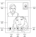
Fig. 1A depicts a first exemplary user interface including a broadcast indication (broadcast indication) of a group call.
FIG. 1B depicts an exemplary video call interface.
Fig. 1C depicts an exemplary user interface for receiving broadcast instructions for a group call.
Fig. 1D depicts a second exemplary user interface including a broadcast indication of a group call.
FIG. 2A is a block diagram depicting an exemplary client device/server environment suitable for use in various embodiments.
Fig. 2B depicts an exemplary data structure for exchanging messages.
Fig. 3A-3B are data flow diagrams depicting exemplary information exchange in a client device/server environment.
Fig. 4A-4B depict a flow diagram illustrating an exemplary method for coordinating and broadcasting a group call.
Fig. 5A is a block diagram providing an overview of a system including an exemplary centralized communication service.
Fig. 5B is a block diagram providing an overview of a system including an exemplary distributed communication service.
FIG. 5C depicts the social network diagram of FIGS. 5A-5B in more detail.
Fig. 6 is a block diagram depicting an example of a system for a messaging service.
FIG. 7 is a block diagram illustrating an exemplary computing device suitable for use in exemplary embodiments.
Fig. 8 depicts an exemplary communication architecture.
Fig. 9 is a block diagram depicting an exemplary multi-carrier communication device.
Detailed Description
The present application describes a new protocol for broadcasting and managing virtual call participation over digital communication services, such as social media platforms. Users of digital communication services often wish to share events with other users. For example, users of a social media platform may share memory by posting to a "dynamic (Story)" page. A user may interact with others' posts by viewing, commenting on, and expressing approval through an indication such as "like". Posts from one user account may include tags of another user to facilitate interaction of the two users through the digital service in a manner that is visible to the other user. However, these interactions are typically limited to only typed comments and/or static images. Current platforms lack a way for users to share virtual conversations with others.
For example, a group of users may wish to broadcast evidence (evidence) of a video chat or virtual call (which may be ongoing) to at least one other user of the digital communication service. The only way to do this might be to capture a static image of the call (e.g., screen shot), publish the image as a shared memory, and manually tag other relevant users. This process is inefficient and time consuming and can interrupt ongoing calls.
Furthermore, viewers may see the post and wish to join the call, but they may not be able to join the call without great effort. For example, a viewer may require a participant in a call to manually initiate an invitation, such as a forward link to the call, through a separate communication platform. In many cases, the viewer may not be able to join the group call until all other participants are away from the call. In this example, the viewer may have to manually initiate a new call from a separate platform, including entering contact information for each participant of the original call.
The protocols described herein allow users of a digital communication service to broadcast indications of virtual conversations (e.g., group video calls) to other (e.g., non-participating) user accounts. In some embodiments, the indication may include an invitation to join the virtual conversation. The protocol allows a user to initiate a broadcast of a virtual session over a real-time communication (RTC) channel and coordinate the session across multiple devices. The protocol includes a set of participants exchanging messages to cooperatively establish a conversation, broadcasting an indication of the conversation to at least one non-participating user, and/or managing the conversation.
Thus, when the user is in a real world event (e.g., a party), the RTC video channel is used as a kind of chat (hangout) space. A user may capture a picture of a real-world event while participating in a video chat, and the picture is saved as an artifact in motion (other embodiments allow the user to use an animated GIF, video clip, and other elements as an artifact). The user may add an interactable element to the image (e.g., by selecting a drawer (drawer) with the graphical content). If another user interacts with the element, that user may be brought into video chat. If the video chat has ended, a new video call with the same original participant can be started. This may also encourage people to attend real-world events.
Other aspects provide audience (audio) management features (e.g., techniques to selectively invite participants, invite people as guests (guest) so they do not need to log into a communication service, cross-platform or cross-service invitation), graphical component customization, conflict detection when multiple users request to join a call, and capture techniques.
The protocol may coordinate message exchanges through Application Programming Interface (API) calls. The system is independent of both the data type and the platform. Thus, a dialog may be composed of multiple data types. For simplicity, virtual conversations may be referred to herein as calls, but they will be understood to include, for example, video data, audio data, text data, or any combination thereof. The broadcast indication may include an image, a graphic interchange Format File (GIF), a short video, live conversation (live conversation) data, a sticker (packer), or any combination thereof. Thus, a user or group of users may customize conversation sharing.
This brief summary is intended as a non-limiting introduction to the concepts discussed in greater detail below. However, before discussing further exemplary embodiments, a brief explanation regarding data privacy is first provided. A more detailed description of privacy settings and authentication will be set forth in conjunction with the following figures.
Description of data privacy
Some embodiments described herein utilize training data or metrics, which may include information voluntarily provided by one or more users. In such embodiments, data privacy may be protected in a variety of ways.
For example, a user may be required to choose to allow any data collection before collecting or using the user data. The user may also be provided with an opportunity to choose not to allow any data collection. Before choosing to allow data collection, the user may be provided with a description of the manner in which the data will be used, how long the data will be retained, and the security measures taken to protect the data from being compromised.
Any information identifying the user from which data was collected may be purged or disassociated (disassociated) with the data. In the event that any identifying information needs to be retained (e.g., to meet regulatory requirements), the user may be notified of the collection of identifying information, the usage that will be made of the identifying information, and the amount of time that the identifying information will be retained. Information that specifically identifies the user may be removed and replaced with, for example, a universal identification number or other non-specific form of identification.
Once collected, the data may be stored in a secure data storage location that includes security measures to prevent unauthorized access to the data. The data may be stored in an encrypted format. The identification information and/or non-identification information may be purged from the data storage device after a predetermined period of time.
Although specific privacy protection techniques are described herein for illustrative purposes, one of ordinary skill in the art will recognize that privacy is also protected in other ways. Further details regarding data privacy are discussed below in the section describing network embodiments.
Given that the privacy conditions of the user are met, exemplary embodiments may be deployed in a wide variety of messaging systems, including messaging in social networks or on mobile devices (e.g., through messaging client applications or via short message services), among other possibilities. An overview of exemplary logic and processes for participating in a synchronized video conversation in a messaging system is provided next.
To facilitate understanding, a series of examples will first be presented before describing a detailed description of the underlying implementation. Note that these examples are intended to be illustrative only, and the present invention is not limited to the illustrated embodiments.
RTC broadcast of conversations
Reference is now made to the drawings, wherein like reference numerals are used to refer to like elements throughout. In the following description, for purposes of explanation, numerous specific details are set forth in order to provide a thorough understanding thereof. However, the novel embodiments may be practiced without these specific details. In other instances, well-known structures and devices are shown in block diagram form in order to facilitate a description thereof. The intention is to cover all modifications, equivalents, and alternatives consistent with the claimed subject matter.
In the drawings and the accompanying description, the reference numerals "a" and "b" and "c" (and similar indicators) are intended as variables representing any positive integer. Thus, for example, if an implementation sets the value to a-5, the complete set of components 122, shown as components 122-1 through 122-a, may include components 122-1, 122-2, 122-3, 122-4, and 122-5. Embodiments are not limited to this context.
Fig. 1A depicts a first exemplary user interface of a digital communication service including a broadcast indication of a group call. The embodiments are not limited in this context.
The system may include a user interface associated with a user account of the digital communication service. The user interface may include a Graphical User Interface (GUI). For example, the digital communication service may receive a username, password, and/or other security credentials to identify the user account. An account-specific user interface, such as user interface 102-1, may be displayed on a client device, such as a computer, laptop, or mobile phone. An identifier, such as a Universally Unique Identifier (UUID), may be associated with the user account. As described herein, an association with a user will be understood to include an association with a user account of the user.
The user interface may include one or more posts from the associated user account. For example, the user interface 102-1 may include the post 104-1. The post may include an image, screenshot, video, GIF, or other type of data file associated with the user account. Further, the post may include a status, a message, a dynamic, and/or another indicator of at least one user's activity. The user interface may receive input to update, edit, customize, or add posts associated with the user account. For example, the user interface 102-1 may receive input via the first client post button 108-1 to update the post of the associated client, including selecting a particular image, screenshot, video, GIF, or other type of data file to display in the post.
Additionally or alternatively, the user interface may display a post associated with at least one additional user of the digital communication service. In many embodiments, information may be displayed on a user interface according to the relationship of the associated user to the user account of the user interface (e.g., based on a social networking graph). For example, as described below, the social network diagram may be implemented as described with reference to FIG. 5C. In the exemplary user interface 102, the post 104-2 may be associated with a second user account, the post 104-3 may be associated with a third user account, and the post 104-4 may be associated with a fourth user account of a social media service.
In some embodiments, the user account may include a representation and/or identifier of the associated user, where the representation is viewable by one or more other users of the digital communication service. The user indicator 106-1 may include a representation of the user associated with the first client user interface 102-1, such as a Maria's name and/or photograph. Similarly, the user account associated with the post 104-2 may be associated with the user indicator 106-2, the user account of the post 104-3 may be associated with the user indicator 106-3, and the user account of the post 104-4 may be associated with the user indicator 106-4. By way of example only, information for four illustrated accounts is listed. Embodiments may include any number of accounts.
A user interface, such as user interface 102-1, may include notifications associated with user account communications from one or more other user accounts. For example, message notification 110-1 may indicate an unread received message and/or an invitation to engage in a text messaging conversation via a digital communication service. Similarly, video notification 111-1 may indicate an unanswered video call and/or an invitation to participate in a video call via a digital communication service, and call notification 112-1 may indicate two unanswered audio calls and/or an invitation to participate in an audio call via a digital communication service. The user account may receive messages and/or calls from individual user accounts or from a group of other user accounts.
In various embodiments, the user interface 102-1 may include one or more broadcast indications of user participation in the virtual session. The virtual dialog may include text data, video data, audio data, or a combination thereof. Posts from users who are and/or have participated in the virtual conversation may include associated broadcast indications. For example, the broadcast indication 114-3 may be associated with the post 104-3 and indicate that a third user account associated with Janet is engaged in, for example, a video call. Broadcast indication 114-4 may be associated with post 104-4 and indicate that a fourth user account associated with Jose is engaged in the video call. In various embodiments, the broadcast indication may include a sticker displayed on the related post, or the broadcast indication may be displayed as a post to the related user account. The broadcast indication may indicate ongoing, past, or planned virtual conversations between user accounts.
The broadcast indication may include an indication of at least one additional participant in the virtual conversation. Participants may be represented automatically based on their participation in the virtual conversation or based on manual tagging via themselves or at least one additional user account. For example, broadcast indication 114-3 contains information from user indicator 106-4, while broadcast indication 114-4 contains information from user indicator 106-3. The illustrated example may indicate a virtual conversation between user accounts associated with Janet and Jose. The privacy settings may restrict or allow tagging of participants.
Additionally or alternatively, the broadcast indication may comprise an indication of the type of virtual conversation, such as a graphical member, being conducted between users. For example, in broadcast indication 114-3 and broadcast indication 114-4, the image of the camera may indicate that the virtual conversation is a video call.
Broadcast indication 114-3 and broadcast indication 114-4 are illustrated with images to convey participation and conversation type. However, embodiments may additionally or alternatively include text, video clips, GIFs, stickers, expressions, real-time or near real-time data feeds (feeds), capture from virtual conversations, or any combination thereof. The user interface 102-1 may receive instructions to customize the graphical components included in the broadcast indication. For example, the user interface 102-1 may receive an instruction to include a particular GIF as a graphical component.
In some embodiments, the broadcast indication may include an invitation for the at least one user to join the virtual conversation. The invitation may correspond to a notification, such as message notification 110-1, video notification 111-1, or call notification 112-1. In some embodiments, the user interface 102-1 may display the broadcast indication in accordance with an invitation to the user account of the user interface 102-1 to join the virtual conversation. For example, display of broadcast indication 114-3 and/or broadcast indication 114-4 on user interface 102-1 may indicate an invitation for a user account of user interface 102-1 to join a video call.
The user interface 102-1 may receive acceptance of the invitation to join the virtual conversation via a notification, such as the video notification 111-1. If the invitation is accepted after the virtual session is over, the system may automatically initiate a new call between the associated participants, or initiate a new call between the associated participants after receiving confirmation from one or more of the associated participants. For example, selection of a notification may enable user interface 102-1 to direct a virtual conversation. However, in some embodiments, the broadcast indication may navigate directly to the virtual dialog. For example, the user interface may receive a selection of broadcast indication 114-3 and/or broadcast indication 114-4 and then join the associated call.
The user interface may display a call interface based on the joining of the associated virtual conversation. Fig. 1B depicts an exemplary video call interface associated with one or more embodiments described herein. The embodiments are not limited in this context.
The call interface may include at least one data feed from another user account. The data feed may be real-time or near real-time. The data feed may include video data, audio data, or a combination thereof. Some embodiments may include additional data types such as stickers, effects of applications, animations, text, message threads (message threads), or other media types useful for conducting virtual conversations. As shown, call interface 116-1 includes data feed 118-3 and data feed 118-4, each including at least video data.
Data feed 118-3 and data feed 118-4 include data received from user accounts (as shown in fig. 1A) associated with post 104-3 and post 104-4, respectively. The virtual conversation may include a set of participants and/or a predetermined group of participants from a user selection, for example, through a user interface. The call identifier may indicate a virtual conversation between a group of participants. In some embodiments, the channel identifier may indicate a data channel for the virtual session. Participants may join the virtual conversation by using only keys associated with the call identifier and/or the channel identifier (e.g., collision key).
The virtual session may be joined based on a received selection of an invitation, such as an invitation included in broadcast indication 114-3 or broadcast indication 114-4 in fig. 1A. In various embodiments, the broadcast indication may include a call identifier that uniquely identifies the virtual dialog. The call identifier may include a channel identifier, link, and/or collision key for initiating and/or joining a particular conversation.
Joining the conversation may include capturing and sending data feeds associated with a user account for accessing the call interface 116-1. In some embodiments, the call interface 116-1 may include a preview of the captured visual data. For example, the data feed 118-1 may be a preview of video data captured by a user device accessing the call interface 116-1 through a particular user account.
Joining a conversation may result in updating a set of associated user and/or participant lists to include the joined user account.
In addition to at least one data feed, the call interface 116-1 may include one or more options to receive instructions related to the virtual conversation. For example, video feed button 120-1 may be used to switch the capture and/or sharing of video data of a virtual conversation through call interface 116-1. The audio feed button 122-1 may receive an instruction to switch the capturing and/or sharing of audio data of a virtual conversation. The camera selection button 124-1 may receive an instruction to select a camera on a client device for accessing the call interface 116-1. For example, the front camera and the rear camera may be switched. Additional controls that may be included in embodiments include application of call settings, text-based dialogs, or media effects associated with virtual dialogs.
The call interface 116-1 may include an option to receive instructions to leave and/or end the virtual conversation. For example, call interface 116-1 may include an end call button 126-1. Upon receiving an instruction to leave the virtual dialog, the system may redirect the user from the call interface 116-1 to another interface, such as the user interface 102-1.
In many embodiments, call interface 116-1 may include an option to broadcast a call record (e.g., a broadcast indication as described with respect to fig. 1A). The broadcast indication may be automatically broadcast based on a user account joining the virtual session. In particular, the system may learn of the acceptance of the invitation to join the virtual session to indicate the user's consent to share the broadcast indication. Additionally or alternatively, sharing of broadcast indications may be limited and/or managed according to input received via the call interface 116-1 or user settings of the digital communication service. In some embodiments, the call interface 116-1 may receive instructions for managing broadcast instructions via the add participant button 128-1.
Fig. 1C depicts an exemplary user interface for receiving broadcast instructions for a group call. The add participant button 128-1 may enable the system to receive one or more instructions to share broadcast instructions associated with the virtual session with one or more additional user accounts. For example, options such as add participant buttons may enable the system to provide dialog management options through a menu. Additionally or alternatively, the system may receive broadcast instructions for the virtual dialog via a broadcast setting or via another option at the time of the dialog initiation. The embodiments are not limited in this context.
The dialog management menu 130-1 may include one or more options for managing the broadcast or sharing of virtual dialogs. The conversation management menu 130-1 may include a participant list 132-1, which may provide an indication of at least one user account associated with the virtual conversation. In particular, participant list 132-1 may include indications of some or all of the accounts that participated in and/or were invited to participate in the virtual conversation.
Additionally or alternatively, the dialog management menu 130-1 may include one or more options to include other users in the virtual dialog. A single user account (e.g., additional participant 134-2) or multiple user accounts may be selected for conversation sharing. The selection of the user to be invited to participate in the group conversation may be based on a phone number, an email address, a username, an internet protocol address, a device identifier, an account identifier, and/or another user identifier. Some embodiments may enable virtual conversations to be shared with a group of users (e.g., additional participant group 136-2). The user group may be determined manually, e.g., by a user via a user interface, or automatically, e.g., based on proximity and/or relationship to a user account in a social networking graph.
Conversation sharing may extend across platforms. For example, a participant in a virtual conversation may send an invitation to a user who is not a digital communication service and/or additional participants who are not logged into the digital communication service. In some embodiments, at least one participant may be a user of a supported service (e.g., an approved substitute virtual conversation service).
The system may receive instructions to broadcast an indication of a virtual conversation to one or more additional users according to one or more selected sharing options 138-1 and/or invitation options 140-1. The sharing option 138-1 and/or the invitation option 140-1 may be determined separately for potential additional participants and/or groups of additional participants.
The broadcast indication may or may not include an invitation to a virtual conversation, depending on the sharing option 138-1 and/or the invitation option 140-1. In FIG. 1C, selection of the sharing option for Brittany may result in sending a broadcast indication to a social media user interface associated with Brittany. However, the absence of selection of the invitation option may result in the broadcast indicating an invitation and/or identifier that does not include a virtual conversation. In this way, the presence of a conversation can be shared with the participants' friends without issuing a disclosure invitation to the unwanted users.
A broadcast indication that does not include an invitation to a virtual conversation may not be directed to the conversation if selected by the user via a user interface, such as user interface 102-1. In some embodiments, based on the selection of the broadcast indication by the user account, a request to join the user account to the virtual conversation may be sent to one or more participating accounts of the conversation without an invitation to the call.
The broadcast settings 142-1 may determine group definitions, privacy settings, default and/or custom sharing options 138-1 and invitation options 140-1 associated with the user account.
In some embodiments, only the initiating user account (initiating user account) of the virtual session may manage the participants. In some embodiments, at least one additional participant of the conversation may manage the participants. For example, a user account used to access user interface 102-1 may manage the participants of a video conversation, including other participants after joining the conversation via a broadcast indication. Default settings may establish administrative privileges for participants. Alternatively or additionally, settings established by a user account or another method useful for efficiently determining privileges may establish administrative privileges.
Various embodiments may coordinate management of participants across multiple user accounts. For example, inviting another user account to join a virtual conversation may require approval by some or all of the current participants of the conversation.
Determining, by one or more user accounts, that the broadcast indication should be shared may result in the broadcast indication being displayed with the one or more user accounts. For example, determining, by the user account of Janet, an indication of a video call with the user account of Jose may result in broadcasting a post 104-3 indicating an account with Janet or both a post 104-3 and a post 104-4 associated with Jose's account being displayed. The inclusion of an invitation in a broadcast indication may similarly be applied to broadcast indications displayed with one or more user accounts.
The determination of which accounts may display the broadcast notification may be made according to a pre-configuration of at least one participant and/or one or more privacy settings. In many embodiments, a more conservative privacy setting for one user will take precedence over a less conservative privacy setting for another user. For example, if the privacy settings of Jose's user account indicate a limitation on the distribution of this information, the broadcast indication may not be displayed with Janet's post 104-3, or broadcast indication 114-3 may not include an indication of Jose's participation.
In many embodiments, the broadcast notification 144-1 may communicate a broadcast of the participant's indication of the virtual conversation to at least one other participant of the conversation. For example, the broadcast of a public invitation to the call by participating user Jose may be communicated to the other participating users Maria and Janet through a broadcast announcement. Thus, the participants of the virtual conversation may be informed which other user accounts may access the conversation.
The broadcast indication shared by the user accounts participating in the virtual session may be viewable by at least one additional user account. In many embodiments, the at least one viewer broadcasting the indication may not be a participant of the associated virtual conversation. For example, sharing broadcast indications with Brittany via sharing option 138-1 may result in at least one broadcast indication being displayed on a user interface that is accessed by a user account of Brittany on the digital communication platform.
Fig. 1D depicts a second exemplary user interface including a broadcast indication of a group call. FIG. 1D may correspond to the exemplary use case (use case) shown in FIG. 1C. The embodiments are not limited in this context.
A user account receiving the broadcast indication of the virtual dialog may access a user interface, such as user interface 102-2. The user interface may have various components that are the same as or similar to user interface 102-1. For example, user interface 102-2 may include user indicator 106-2 that is similar to user indicator 106-1 but associated with a different respective user. The user post button 108-2 may receive input for editing, adding, and/or updating a user post of a user account associated with the user interface 102-2. The functionality of the notifications may be similar to those described with respect to FIG. 1A, but specific to the account, including message notification 110-2, video notification 111-2, and call notification 112-2.
The user interface 102-2 may display one or more broadcast indications associated with the call interface 116-1 associated with the share option 138-1. When Maria's user account has joined a call between Janet and Jose's user account, the broadcast indication subsequently displayed on user interface 102-2 may reflect the updated participant list. For example, broadcast directive 148-1 associated with Maria's user account may instruct Maria's user account to participate in a virtual conversation with Janet and Jose's user account. Broadcast directive 148-3 associated with the user account for jane may indicate participation in video calls with the respective user accounts for Maria and Jose, while broadcast directive 148-4 associated with the user account for Jose may indicate participation in video calls with Maria and jane.
In some embodiments, the broadcast indication may include a post associated with the user account. For example, the post 104-1 may be replaced and/or updated with the post 146-1 associated with Maria's user account when the user account joins a video call. Post 146-1 may include an image, a frame captured from a virtual conversation, a graphic interchange Format File (GIF), a short video, live conversation data, a sticker, or any combination thereof in a custom graphical artifact. In various embodiments, the content of the graphical component in the post 146-1 may be captured (e.g., via a screen shot) from the virtual conversation.
As with the broadcast notification, the content of the post 146-1 may be predetermined or determined based on input received via the user interface. Users participating in the conversation may be automatically tagged in the post or tagged according to input received via the user interface.
The post 146-1 including the broadcast indication may be selected to view more information about the relevant conversation, such as a participant list, according to the privacy settings of the participants. Post 146-1 may include an invitation to join the conversation. For example, the post 146-1 may include an invitation to a particular user or group of users based on input received from the participant. Selecting a post that includes an invitation to a virtual conversation may enable the system to navigate directly to the conversation. Selecting a post that does not include an invitation to a virtual conversation may enable the system to send one or more requests to join the conversation to at least one participating user account. The requested approval, e.g., the approval received through the user interface, may result in the requesting user being added to the virtual dialog. Accordingly, the associated participant list and/or broadcast indication may be updated.
Various embodiments may broadcast at least one indication to participate in a historical virtual session. For example, the recipient of the invitation may not be able to join the conversation until all active participants have left the conversation. The participant list may be associated with a call identifier and/or a broadcast indication. Thus, selecting an invitation to a virtual conversation without the remaining participants may result in automatic re-initiation of the conversation. For example, all participants in the participant list may be recalled. Accordingly, the participants can return to the historical conversation without the need to identify and input contact information of each of the other participants, thereby improving the convenience of the digital communication service.
Exemplary System configuration and data Structure
Fig. 2A depicts an exemplary system for broadcasting and managing a participation group virtual conversation. The embodiments are not limited in this context.
The system may enable virtual conversations, which may be, for example, one-to-one, one-to-many, or group communications. In many embodiments, the virtual conversation may include video communications. Alternatively or additionally, the system may facilitate broadcast of at least one indication of a virtual dialog. Embodiments may also include managing participation in a virtual conversation based on received input related to the broadcast indication. One example will be described below with reference to broadcasting an indication of a video call and managing participation in the video call; however, it should be understood that the present application is not limited to this example.
The initiating client device (initiating client device)202-1 may be a device associated with a first participant in a communication. The initiating client device 202-1 may be, for example, a mobile device (although the invention is not limited to applications of mobile devices) that executes a communication application 404-1 for participating in a coordination activity with one or more other participants, such as video communication of a video-based conference call. The initiating client device 202-1 may be a device that initiates a coordination effect that is used at or applied by one or more non-initiating client devices (non-initiating client devices) 202-2, 202-3, 204-4, etc.
The communication application 204-1 may cause information associated with the video communication to be transmitted to one or more servers that facilitate the communication. For example, the information may include video data 208 containing video frames associated with the communication, audio data 212 containing sound information to be synchronized with the graphics frames, and control data 216. The control data 216 may include various instructions, identifiers, metadata, etc. for applying a coordinating effect associated with (e.g., synchronized with) the video data 208 and the audio data 212.
In some embodiments, video data 208 and audio data 212 may be captured by components of one or more client devices, such as originating client device 202-1 or non-originating client devices 202-2, 202-3, 204-4, and so forth. In some embodiments, the communication application 204-1 may include a user interface for a digital communication service, such as a social media platform. In various embodiments, the communication application 204-1 may display at least one broadcast indication associated with the video communication.
Each type of data may be transmitted in an associated channel. For example, the communication application 204-1 or another component of the initiating client device 202-1 may open the video channel 206, the audio channel 210, and the control channel 214 involving the communication server 218. The video channel 206 may carry only video data 208 in video format. Thus, the communication server 218 may treat any data received over the video channel 206 as data in video format and may process the data appropriately. Similarly, the audio channel 210 may carry only audio data 212 in an audio format.
It should be understood that the present invention is not limited to transmitting video data 208 and audio data 212 over video channel 206 and audio channel 210, respectively. For example, where the virtual dialog is a message thread, the graphics data may be shared in a data channel. In examples involving multiplayer games, game data may be shared in a data channel dedicated to conveying information about game state. For a group audio call, the channels may include an audio channel 210, but no video channel 206. In each case, the control channel 214 may be a real-time or near real-time channel that is separate and distinct from the data channel.
The control channel 214 may transmit general data that is not necessarily in a predetermined format, or may transmit control instructions in a particular control format. For example, control channel 214 may carry instructions to adjust access to video data 208 and/or audio data 212, or may carry instructions to send a broadcast indication to at least one other client device. The control channel 214 may be, for example, a Web real-time communication (WebRTC) channel.
The video channel 206, audio channel 210, and control channel may communicate information in both directions. Thus, for example, video channel 206 and audio channel 210 may carry data for display/playback on originating client device 202-1 (e.g., data related to a video stream of one or more non-originating client devices 202-2, 2-3, 202-4). The control channel 214 may carry instructions from the communication server 218 for managing access to the virtual session and/or other instructions.
The communication server 218 may be configured to coordinate the sharing of broadcast indications of virtual conversations between one or more initiating client devices 202-1 and one or more non-initiating client devices 202-2, 202-3, 202-4, etc. by applying broadcast management logic 220. Additionally or alternatively, communication server 218 may be configured to manage participation in virtual conversations between one or more originating client devices 202-1 and one or more non-originating client devices 202-2, 202-3, 202-4, etc. by applying call management logic 222. The communication server 218 may also store a media effects library 224 that includes data related to a plurality of broadcast indications. For example, the broadcast indication medium may include a graphic member such as an image, GIF, or the like. The broadcast indication media may be identified by an identifier, and the media effects library may optionally mirror (mirror) a media effects library stored locally at the client device 202. Alternatively or additionally, the library stored at the communication server 218 (or split among multiple communication servers 218) may be partially cached at the local client device 202. In some cases, the local client device may include a short (thumbnail) version of the coordination effect, allowing selection of the effect in the communication application 204, but saving storage on the client device 202 by not including implementation details of the coordination effect. When applying the coordination effect, the respective client device 202 may request implementation details from the communication server 218.
The communication server 218 may also include audio-visual editing logic (audiovisual editing logic)226, the audiovisual editing logic 226 for combining the video data 208, the audio data 212, and any broadcast indications. The audiovisual editing logic 226 may include logic to synchronize the audio data 212 with the video data 208 and further to apply a broadcast indication to the combined audio/video data (or to the audio data 212 or the video data 208 alone). For example, the audiovisual editing logic 226 may coordinate the composition and application of broadcast indications including video data from a virtual conversation.
Once combined, the synthesized audiovisual data 232 may optionally be transmitted from the communication server 218 to the broadcast server 228. The broadcast server 228 may include broadcast logic 230 that identifies one or more recipients associated with the video communication, such as the non-originating client devices 202-2, 202-3, 202-4. The broadcast server 228 may send audio-visual data 232 including the audio data 212, the video data 208, and/or at least one broadcast indication to each recipient.
In some cases, the audio-visual data 232 may be broadcast to all recipients, but messages related to the broadcast indication and/or call participation management may be transmitted to the non-originating client 202-i over a corresponding control channel 214. In some embodiments, control data 216 may also be provided to some or all of non-originating clients 202-i.
For example, in the example shown in fig. 1A, a video call may be initiated by a device of Janet and may need to be coordinated with a device of Jose in order to extend the broadcast indication including the invitation to a device of Maria. For example, the broadcast indication may be sent only after approval by both Janet and Jose, and/or the broadcast indication may include data capture from Jose's devices. Although the video data may continue to be broadcast by the broadcast server 228 when the broadcast indication is coordinated, the control data provided to and from each device may vary. For example, the device of Janet may send a start instruction on control channel 214, which may be relayed to the device of Jack. The Jack's device may send acknowledgements, data, etc. to the communication server 218 over its respective control channel 214 (not shown). The broadcast indication may then be transmitted from the communication server 218 to Maria's devices.
Each device may send/receive control data 216 to/from communication server 218 to allow one or more notifications of broadcast indications, such as broadcast notification 144-1, to be displayed on their respective user interfaces. In an embodiment, the broadcast notification may be applied to the corresponding audio data 212 and/or video data 208. Alternatively, the notifications may be applied locally by the respective client device. The audiovisual data 232 modified with the broadcast notification may be transmitted by the broadcast server 228 to each participant in the virtual session.
Although fig. 2A depicts a specific example involving coordination between a client and a server, it should be noted that the present invention is not limited to such an embodiment. In other examples, multiple servers may be used, or a server may not be used. For example, in a peer-to-peer implementation, the originating client device 202-1 may communicate directly with the non-originating client devices 202-2, 202-3, 202-4 without the assistance of the intermediate communication server 218 and/or the broadcast server 228. In such embodiments, the various clients may implement broadcast management logic 220, call management logic 222, media effects library 224, and/or audiovisual editing logic 226. In some embodiments, clients 202-i may communicate in a peer-to-peer manner, but may be supported by one or more servers (e.g., servers storing media effects library 224).
Fig. 2B depicts an exemplary data structure for exchanging messages. The embodiments are not limited in this context.
Exchange message 250 may be sent by the client device to the communication server and/or another client device to broadcast an indication of the virtual session and/or to coordinate the virtual session. The communication server may receive the exchange message 250 over the RTC channel.
Exchange message 250 may include a flag 252 or other identifier to allow identification of exchange message 250 as relating to the broadcast and/or management of the virtual session. Flag 252 may identify exchange message 250 as including a broadcast indication, a call initiation request, a call identification message, an invite acceptance, a broadcast request, a join approval, a broadcast notification, and/or other messages. Fig. 3A-3B illustrate various exemplary messages in more detail. In many embodiments, exchange message 250 may include a flag 252 in the header data. The flag 252 may enable the communication server 218, the broadcast server 228, and/or the client device receiving the exchange message 250 to easily identify and process the message.
Exchange message 250 may contain call identifier 254. Call identifier 254 may uniquely identify a virtual conversation between a group of participants. In some embodiments, call identifier 254 may include a channel identifier, link, and/or collision key for initiating and/or joining a particular conversation. The channel identifier may identify a data channel for the virtual session.
In some embodiments, the call identifier may include a channel identifier and/or link that is accessible only when certain security measures are satisfied. For example, the data channel and/or link of exchange message 250 may be accessed and/or used by participants only at login or after login to the digital communication service. In some embodiments, the call identifier may include a channel identifier and/or link that is open to participants that are not logged into the particular digital communication service. For example, a participant possessing a call identifier and/or link may indicate that the participant is invited to join the call as part of the participant list 258.
Participants may join the virtual conversation simply by using a key (e.g., a bump key) associated with the call identifier and/or the channel identifier. Call identifier 254 may thus enable a participant to join the correct virtual conversation.
Exchange message 250 may include participant data 256. Participant data 256 may include data that associates exchange message 250 with one or more user accounts. In many embodiments, the participant data 256 may include a participant list 258 and/or message data 260.
The participant list 258 may include information related to at least one user participating in a virtual conversation. Participant list 258 may include at least one or more user identifiers, such as a user account UUID, a telephone number, an email address, or an internet protocol address. Participant list 258 may include the intended recipient user account and/or user device exchanging messages, e.g., with an invitation to join the virtual conversation. In some embodiments, the participant list 258 may include an identifier of the sending user account and/or user device. Additionally or alternatively, participant list 258 may include user accounts associated with the virtual session, such as user accounts participating in the virtual session. For example, if the exchange message 250 includes a broadcast indication, the participant list 258 indicating the user account sending the invitation may enable a notification to be displayed on the recipient's user interface accordingly. In another example involving a broadcast indication, the participant list 258 indicating the participants of the video call may enable the system to display the broadcast indication with the user posts of the participants. For example, broadcast indications 148-1, 148-3, and 148-4 may be displayed on Brittany's user interface 102-2 along with posts from users Maria, Janet, and Jose P, respectively.
Additionally or alternatively, participant data 256 may include message data 260. Message data 260 may include data associated with at least one user account that may be used to process the exchange message. In many embodiments, the message data 260 may include data associated with each participant in a series of participants in the participant list 258. The message data 260 may include one or more user indicators or message content that are displayed with the participants. For example, if exchange message 250 includes a broadcast indication in the context of the example of FIG. 1D, message data 260 may include user indicators 106-1, 106-3, and 106-4 associated with respective identifiers of participants Maria, Janet, and Jose. Additionally or alternatively, the message data 260 may include the context of stickers and/or posts displayed on the user interface as or in association with the broadcast indication. For example, the message data 260 may include a screenshot of a video call used in the post 146-1.
In some embodiments, message data 260 may additionally or alternatively include data regarding the context in which message 250 is exchanged, such as a timestamp and/or a geo-location tag (geotag). The message data 260 may include privacy and/or other user settings associated with at least one user account. In some embodiments, message data 260 may include at least one indication of a requested conversation share associated with at least one user account. For example, the exchange message 250 including the request to initiate a video call may include message data 260 containing a broadcast indication to be shared with one or more designated users in the participant list 258 upon successful call initiation. The user account may be assigned various levels of participation in the participant list 258 or virtual conversations associated with the participant list 258. For example, the user account may be a call originator, a call participant, a broadcast indication recipient, an invitation recipient, or other designation.
In some embodiments, participant data 256 may include data to be sent directly to one or more servers and/or client devices, as described herein. Alternatively or additionally, the participant data 256 may include one or more pointers to locations where data is stored. The receiving device may then access the data after receiving exchange message 250.
Data flow and exemplary method
Fig. 3A-3B depict data flow diagrams depicting exemplary information exchange in a client device/server environment. Various embodiments, such as those shown in FIG. 2A, may implement this exchange of information. Embodiments may include more than one non-originating client device 202-i, in which case the exchange of information between the communication server 218 and the non-originating client device 202-2 may be performed between the communication server 218 and each non-originating client device 2-i. However, for simplicity, only two involved client devices are shown with respect to fig. 3A-3B. The embodiments are not limited in this context.
Fig. 3A illustrates a flow of information useful for managing the initiation of a virtual session. An initiating client device 202-1, such as that shown in fig. 2A, may send a request 302 to begin a virtual conversation with a non-initiating client device 202-2. Request 302 may be in the form of exchange message 250 (as shown in fig. 2B). For example, exchange message 250 may include a flag 252 indicating an initiation request for a video call, and participant data 256. In this example, the participant data 256 may include a participant list 258 containing identifiers of the originating client device 202-1 as the sender of the request and identifiers of the non-originating client device 202-2 as the recipient of the request, and message data 260 containing user indicators for the originating client device 202-1 and the non-originating client device 202-2. Originating client device 202-1 and non-originating client device 202-2 may be associated with the same or different digital communication platforms and/or services.
In some embodiments, the call identifier may be determined and/or provided by communication server 218, and thus the call identifier 254 field of exchange message 250 for this purpose may be empty or non-existent. In other embodiments, the call identifier may be determined by the originating client device 202-1 prior to sending the request 302. In this example, call identifier 254 may include a call identifier.
The request 302 may be generated by an application of the initiating client device 202-1 in response to determining that a virtual dialog is desired (e.g., in response to an input received through a user interface of the device).
Upon receiving the request 302, in embodiments, the communication server 218 may return call information 304 to the originating client device. In some embodiments, the communication server may populate the call identifier 254 field in the call information exchange message 250, thereby enabling the originating client device 202-1 to connect to the virtual conversation. For example, the communication server 218 may generate a collision key for the request 302. In other examples, the initiating client device 202-1 may generate the collision key to be included in the initial request 302. The collision key may be based on the call channel, a timestamp associated with the call, a participant list, other aspects of the call identifier 254, or any combination thereof, so as to uniquely apply to a particular call.
Additionally or alternatively, the communication server 218 may identify one or more non-initiating user devices to which the request 302 is directed (e.g., based on the participant list 258 in the exchange message 250) and may send the invitation 306 to the identified devices. The communication server 218 may identify the recipient of the request 302 and/or send the invitation 306 in response to receiving the request 302. The invitation 306 may include one or more aspects of the request 302. For example, the invitation 306 may be the forwarded request 302. However, additional and/or different information may be included in the invitation 306, such as the call identifier 254. In some embodiments, call identifier 254 may not be included in invitation 306 or any other exchange message 250 to the client device until the client device accepts the invitation.
In some embodiments, the invitation 306 may include an invitation to log in, join, download, or otherwise participate in the digital communication service. In other embodiments, the invitation 306 may additionally include an option for the invited participant to join the virtual conversation without explicitly downloading or joining the digital communication service. For example, the invitation 306 may include a link to a channel (such as a calling line, video conference channel, or other platform) accessible outside of the digital communication service. The calling line, video conference channel, or other platform may be accessed via a network connection external to the digital communication service, enabling participants to interact with the virtual conversation of the invitation 306 without having to join and/or download a digital communication service that they did not previously have.
In some embodiments, the invitation 306 may include an invitation to a virtual dialog that is only accessible from approved platforms. For example, if a channel is accessed from an approved partner platform (partner platform) of a digital communication service, the virtual dialog for the channel may be accessed directly. In the same example, if the channel is not accessed from an approved partner platform of the digital communication service, the invitation is to join, download, or otherwise participate in the digital communication service. When a participant with authenticated access to the partner platform of the digital communication service accesses the invitation 306 from the partner platform, the user may not need to authenticate their identity in order to access the call for the digital communication service. Authenticated access may be identified based on a public user identifier between the partner platform and the digital communication service, an indicator on a response 308 corresponding to the invitation 306, receipt of a response 308 corresponding to the invitation 306, or other methods.
The communication server may receive response 308 from non-originating client device 202-2. The response 308 may be an exchange message 250 that includes an acceptance or rejection of the invitation 306. In some embodiments, the communication server 218 may only receive a response 308 indicating acceptance when determining to accept all aspects of the invitation 306. For example, the determination may be based on broadcast information of the invitation 306 corresponding to settings of the non-originating client device. Alternatively or additionally, it may be determined that the user has approved the broadcast information associated with the invitation 306 based on input received via a user interface of the non-originating client device. In some embodiments, the communication server 218 may receive a response 308 including the participant's authentication (e.g., user login information for a digital communication service).
In some embodiments, the response 308 may include a decline invitation 306. The rejection may be based on input received from the user via the non-originating client device 202-2. In some embodiments, the rejection may be received via input or automatic logic based on the broadcast information of the invitation 306. In some embodiments, response 308 may include the proposed alternate broadcast information, for example, in message data 260.
For example, response 308 may include declining invitation 306 based on the non-initiating user declining to broadcast the virtual conversation to all of the initiating user's friends in the social networking graph. In this example, the response 308 may include proposed alternative information including instructions to broadcast the conversation indication to a subset of the common friends of the two users.
In response to receiving the response 308 with the proposed alternate broadcast information, the communication server 218 may forward the response 308 to the initiating client device 202-1. In this case, the initiating client device 202-1 may send a new request 302 to the communication server 218 with the same or different broadcast information as included in the response 308. The second request (second request)302 may include a call identifier 254 that is the same as or different from the call identifier associated with the original request 302 and/or provided by the communication server 218.
In some embodiments, the information exchange may continue until the communication server 218 receives a response 308 indicating acceptance of the invitation 306, or the flow may be interrupted, for example, because the communication server 218 did not receive additional requests 302 or responses 308 from the client device. In this manner, the system may manage the initiation of virtual conversations based on coordinated broadcast indications from two or more devices.
Based on receiving the response 308 including the acceptance invitation 306, the communication server 218 may send call information 310 to one or more client devices. The call information 310 may include at least the call identifier 254 and the updated participant list 258, including the non-originating client device 202-2 as participants in the conversation.
In some embodiments, response 308 may include call identifier 254, such as a bump key. The call identifier 254 of the response 308 may be the same or based on the call identifier received from the communication server 218 in the invitation 306. The communication server 218 may compare the call identifier 254 received in the response 254 with the call identifier received in the corresponding request 302 or generated in response to the corresponding request 302. Communication server 218 may send call information 310 to non-originating client device 202-2 based only on a match between call identifier 254 of response 308 and a call identifier received in or generated in response to a respective request 302. Thus, the communication server 218 may only allow the non-originating client device 202-2 to join the virtual conversation based on the direct invitation in the request 302 for the call by the non-originating client device 202-2. Thus, the communication server 218 may improve call security and/or improve call experience by reducing the likelihood that a non-originating client device 202-2 incorrectly connects to a virtual conversation (e.g., a virtual conversation of an unrelated request 302 received at the communication server 218).
Fig. 3B depicts an information flow for managing the broadcast and/or participation of a virtual session after session initiation. First client device 312, second client device 314, or both, are not originating client device 202-1 or non-originating client device 202-2. The embodiments are not limited in this context.
The first client device 312 may begin the information exchange of fig. 3B to send a broadcast indication to the client device 314. In particular, the first client device 312 may transmit a broadcast request 316. The broadcast request 316 may include an exchange message 250 containing at least a flag 252 indicating a broadcast indication and/or invitation, a participant list 258 including an identifier of the second client device 314, and message data 260 including data for display on the broadcast indication. In some embodiments, broadcast request 316 may include call identifier 254.
Upon receiving the broadcast request 316, the communication server 218 may identify the second client device 314 as a recipient based on the participant list 258 of the broadcast request 316. Accordingly, the communication server 218 may send the broadcast packet 318 to the second client device 314. In some embodiments, the broadcast packet 318 may include at least some aspects of the broadcast request 316. In some embodiments, the broadcast packet 318 may include data formatted by the communication server 218. For example, broadcast request 316 may include instructions in message data 260 for including a broadcast indication of video data from the virtual session. In this example, the communication server 218 may use the audiovisual editing logic 226 to edit the data for the broadcast instructions. The broadcast packet 318 may then include the composed audiovisual data in the message data 260.
In some embodiments, the information flow of fig. 3B may end after the second client device 314 receives the broadcast packet 318. However, at the second client device, selecting the broadcast indication, e.g., via a user interface, may result in a join request 320 being sent from the second client device 314 to the communication server 218. If the broadcast packet 318 includes an invitation to join the virtual conversation, the join request 320 may include an indication of acceptance or rejection of the invitation from the second client device 314.
If the join request 320 contains an acceptance of the invitation, the call information 310 may be sent to the first client device 312 and the second client device 314. The call information 310 may include a participant list 258 that is updated to include an identifier of the second client device 314.
If the join request 320 contains a rejection of the invitation, the join request 320 may be forwarded by the communication server 218 to the first client device 312 and the information flow stops. Thus, the first client device may be notified that the other user declined the invitation.
In some embodiments, the broadcast packet 318 may not include an invitation to join the call. Selection of the resulting broadcast indication at second client device 314 may then not instruct the system to send exchange message 250 from second client device 314, and the user may not be able to join the virtual conversation.
However, some embodiments may enable a user of second client device 314 to request participation in a virtual conversation even if no broadcast indication containing an invitation is received. In particular, selection of the broadcast indication at the second client device may result in sending a join request 320 to the communication server 218. The join request 320 may be relayed to the first client device 312 by the communication server 218. In some embodiments, a notification of the join request 320 including the identifier of the second client device may be presented to the user via a user interface of the client device 312.
Based on the acceptance of the join request 320 at the first client device 312, a join approval 322 may be sent to the communication server 218. Accordingly, aspects of the call information 310 may be sent to the first client device 312 and/or the second client device 314. For example, call information 310 including the updated participant list 258 may be sent to both client devices. In another example, the call information 310 sent to the second client device 314 may include the call identifier 254, allowing the second client device 314 to join the call.
Thus, upon approval of the participants in the call, the system may provide the user with the flexibility to join the virtual conversation even if the user is excluded from the list of invited participants. As a result, if, for example, a participant forgets to invite a particular user to join a virtual conversation, a new call need not be initiated.
Next, exemplary logic 400A-400B for indicating and/or managing participation in a broadcast virtual session is described in connection with fig. 4A-4B. Fig. 4A-4B organize the depicted logical blocks into various logical groups (e.g., request receiving logic 402, request forwarding logic 406, etc.). In some embodiments, these logic modules may be provided on the communication server 218, as shown in FIG. 2A, although it will be understood that such a configuration is not required. All modules may be implemented in the same device or may be distributed among any number of devices. Various combinations of the modules may be used on a given device or the logic of a single module may be performed by different devices.
Processing begins with request reception logic 402, which may receive instructions using a network interface. The network interface may listen for instructions on the RTC channel. The instruction may be a request to begin a virtual session received from the initiating client device 202-1, as described in connection with fig. 3A.
At block 404, the system may receive a request to initiate a virtual dialog, for example, via request 302. The virtual conversation may include a video call, a dedicated text message thread, an audio call, other call types, or a combination thereof. The system may identify one or more client devices associated with the call, such as originating client device 202-1 and at least one non-originating client device 202-i. In some embodiments, at least one non-originating client device 202-i may be determined based on a selection from an originating client device. The participant list 258 of the broadcast request 316 may identify at least one non-originating client device 202-i
Processing may then be handed over to request forwarding logic 406. At block 408, request forwarding logic 406 may forward the instruction to the non-initiating client device identified in the instruction via the RTC channel using the network interface, e.g., via the logic described with reference to fig. 3A.
Processing may then be handed over to agreement receipt logic (acquisition receipt logic) 410. Optionally, agreement receipt logic 410 may ensure that the instructions are delivered to the non-originating client (blocks 412-414), for example, by retransmitting the instructions to the respective client until the client acknowledges receipt of the instructions or sends a response message.
In response to the instruction, the non-initiating client may respond with one of several different types of messages, such as response 308, on its RTC channel. In block 416, the system may determine whether the response is a confirmation that a virtual session has been or will be started with the non-originating client. If the determination at block 416 is "yes," processing may switch to response forwarding logic 426.
On the other hand, if the determination at block 416 is "no," then processing may proceed to block 418 and the system may determine whether the message is a rejection of the reconciliation effect. If so, processing proceeds to block 420, where the system may forward the rejection back to the originating client at block 420.
At block 422, the system may determine whether to reject broadcast information that includes alternative offers as described above. If not, the system may cancel the initiation of the virtual session, or may initiate a virtual session with a subset of the non-initiating clients. Processing may then end. If included, however, processing may return to request receiving logic 402, at which point embodiments may receive additional request data, as described above.
Together, block 420 and block 422 may comprise broadcast license coordination logic 424. In various embodiments, the steps may be performed in any order.
At block 428, the response forwarding logic 426 may forward the response (e.g., the response 308) to the one or more devices identified in the participant list 258 via the RTC channel using the network interface.
Processing may then be handed over to call information forwarding logic 430. At block 432, the call information forwarding logic 430 may forward the call information to one or more devices via the RTC channel. As described above, the call information may include an updated participant list and be sent to the originating client device and one or more non-originating client devices.
Turning to fig. 4B, processing may proceed to data transfer logic 444, where the system may receive data regarding the virtual session. For example, the data may include video data, audio data, text data, other media data useful for conducting a virtual conversation, or any combination thereof.
In particular, processing may proceed from block 432 to data reception logic 436. At block 438, the data reception logic may receive data, such as video data, related to the virtual session on the RTC channel using the network interface.
Processing may proceed to data forwarding logic 440. At block 442, the logic may cause the network interface to forward data related to the virtual session to one or more client devices participating in the virtual session. In some embodiments, data forwarding may be based on a call identifier, such as call identifier 254. In many embodiments, aspects of data reception logic 436 and data forwarding logic 440 may act simultaneously or sequentially. For example, the concurrent logic operations may enable streaming of data in real-time or near real-time. Together, data reception logic 436 and data forwarding logic 440 may constitute data transmission logic 444.
From block 442, processing may be handed over to broadcast data reception logic 446. At block 448, the broadcast data reception logic 446 may receive broadcast data, such as the broadcast request 316, on the RTC channel using the network interface. From block 448, processing may be handed over to notification logic 450.
At block 452, the notification logic 450 may notify the participants of the received broadcast request. The notification may include sending an exchange message 250 from the broadcast server 228 to one or more devices participating in the virtual session. The exchange message 250 may include a flag 252 indicating a notification, and the participant list 258 may include one or more user identifiers associated with the broadcast request. The logic may identify the recipient of the notification based on the participant list 258. In some embodiments, the notification logic 450 may determine an agreement for coordination of broadcast data between two or more users. In these cases, the notification logic 450 may include logic, components, and/or functionality similar to that of the broadcast license coordination logic 424 and to that of the close association (surround) with the broadcast license coordination logic 424.
Processing may be handed over to the indication generation logic 454. At block 456, the logic may generate a broadcast indication based on the data received by broadcast data reception logic 446. For example, the broadcast indication may include an indication of the type of virtual conversation, one or more user accounts participating in the virtual conversation, and/or media such as images, video clips, GIFs, stickers, frames captured from the virtual conversation, or other video data.
Processing may be handed over to broadcast indication forwarding logic 458. At block 460, the logic may forward broadcast information, such as a broadcast indication, to one or more client devices on the RTC channel. In some embodiments, the broadcast information may be transmitted according to the participant list 258 of the broadcast request 316. As indicated in the broadcast request 316, the broadcast information may be sent to at least one additional user account that is not participating in the virtual session based on user settings of the participating user account and/or based on input received from the participating user account.
Together, the broadcast data reception logic 446, the notification logic 450, and the broadcast indication forwarding logic 458 may comprise broadcast management logic 462. In some embodiments, the broadcast management logic 462 may include one or more aspects of the broadcast management logic 220.
In some embodiments, processing may end after block 460. However, at block 464, the system may alternatively receive an acceptance indication (e.g., via a user interface at the non-originating client device). Acceptance may include selection of a broadcast indication, such as described with respect to fig. 3B. In some embodiments, the indication of acceptance may be a join request 320. As discussed in connection with fig. 3B, the join request may be received based on a broadcast indication that includes the invitation or does not include the invitation.
At block 466, the call management logic 434 may determine whether any participants are participating in the virtual conversation. For example, in some cases, one, some, or each participant initially in the virtual conversation may have left the virtual conversation, such as by using an end call button 126-1 on the call interface 116-1.
If the virtual session is determined to include participants, the call management logic may continue to connect the client device from which the acceptance was received at block 464. In particular, if the acceptance indication received at block 464 is not based on a broadcast indication including an invitation, the logic at block 468 may forward the acceptance received at block 464 to one or more participants in the virtual conversation. Accepted forwarding may include a request to join the virtual session, such as join request 320.
At block 470, if the logic receives approval from one or more devices participating in the virtual conversation, such as join approval 322, the logic may forward the call information, e.g., with the updated participant list, to the one or more participant devices in the conversation. Additionally or alternatively, the call logic may be forwarded to the device from which the acceptance was received at block 464, enabling the device to become a new participant in the virtual conversation.
The logic may then connect the new participant to the virtual session through the data transfer logic 444. Data, such as video data, may be received from the new participant device at data reception logic 436 and forwarded to other participant devices by data forwarding logic 440.
If approval of the join request is not received at block 470, the process may end.
In some embodiments, if an acceptance based on the broadcast indication including the invitation is received at block 464, the logic may proceed directly to block 472 and forward the call information to one or more client devices. Block 472 may include similar logic and/or functionality as block 432. Therefore, the processing can be simplified and the processing requirement can be reduced.
In some embodiments, if an acceptance is received at block 464, but the logic identifies no active participants in the virtual session at block 466, the logic may attempt to re-initiate the virtual session with one or more participants in the virtual session. For example, the system may present options to the client device accepted at block 464 to call back one or more virtual conversation participants. The confirmation via the user interface of the client device may be processed as a request 302 by the request receipt logic 402. Thus, as described in connection with FIG. 3A, the process may be reinitiated with a new initiating client device 202-1. The re-initiated virtual session may be associated with the same or a new call identifier 254 as the original virtual session.
The processes described with respect to fig. 4A-4B may be performed simultaneously with respect to multiple devices. For example, the broadcast request processed by broadcast data reception logic 446 may be received from a client device different from the client device requesting the initial request 302 processed at reception logic 402. In some embodiments, functional blocks such as data transfer logic 444 and broadcast management logic 462 may be executed concurrently so that virtual conversations and conversation broadcasts may be managed across a group of devices.
A single or multiple devices may perform aspects of the processes of fig. 4A-4B. For example, aspects of the agreement receipt logic 410 and/or the call management logic 434 may reside on the communication server 218, the broadcast server 228, and/or a client device such as the originating client device 202-1 and/or the non-originating client device 202-3.
Overview of a communication System
These examples may be implemented by a communication system provided locally, by a client device, or remotely (e.g., a remote server). Fig. 5A-5C depict various examples of communication systems and are discussed in more detail below.
Fig. 5A depicts an exemplary centralized communication system 500 in which functionality such as that described above is integrated into a communication server. Centralized communication system 500 may implement some or all of the structure and/or operation of communication services in a single computing entity (e.g., entirely in a single centralized communication server 526). The embodiments are not limited in this context.
The centralized communication system 500 may generally be arranged to receive, store and communicate messages. Centralized communication system 500 may store messages or video communications while a communication client 520, such as may be executing on client device 510, is offline and transmit messages/communications once the client is available. Alternatively or additionally, client 520 may include social networking functionality.
The client device 510 may transmit a message addressed to the recipient user, user account, or other identifier related to the receiving client device 510. In the exemplary embodiment, each client device 510 and its respective communication client 520 are associated with one or more particular users of centralized communication system 500. In some embodiments, client devices 510 may be cellular devices, such as smartphones, and may be identified by centralized communication system 500 based on a phone number associated with each client device 510. In some embodiments, each communication client may be associated with a user account registered with centralized communication system 500. In general, each communication client may be addressed by various techniques for receiving messages. For example, as described above, client device 510 may be client device 202. Although in some embodiments, the client devices 510 may be cellular devices, in other embodiments, one or more of the client devices 510 may be personal computers, tablet devices, any other form of computing device.
Client device 510 may include one or more input devices 512 and one or more output devices 518. Input devices 512 may include, for example, a microphone, keyboard, camera, electronic pen, touch screen, and other devices for receiving input including message data, requests, commands, user interface interactions, selections, and other types of input. Output devices 518 may include speakers, display devices (e.g., a monitor or touch screen), and other devices for presenting an interface to centralized communication system 500.
The client device 510 may include a memory 519, which memory 519 may be a non-transitory computer-readable storage medium such as one or a combination of a hard disk drive, a solid state drive, flash memory, read only memory, or random access memory. The memory 519 may store a representation of the input 514 and/or a representation of the output 516, as well as one or more applications. For example, memory 519 may store communication clients 520 and/or social networking clients that allow users to interact with social networking services.
The input 514 may be textual, as in the case where the input device includes a keyboard, for example, through the user interface 102-1. Alternatively, the input 514 may be an audio recording, such as in the case where the input device 512 is a microphone. Thus, the input 514 can be subjected to Automatic Speech Recognition (ASR) logic to convert the audio recording into text that can be processed by the centralized communication system 500. The ASR logic may be located at the client device 510 (such that the audio recording is processed locally by the client device 510 and the corresponding text is transmitted to the communication server 526), or may be located remotely at the communication server 526 (in which case the audio recording may be transmitted to the communication server 526 and the communication server 526 may process the audio into text). Other combinations are possible, for example, if the input device 512 is a touch pad or electronic pen, the input 514 may be in handwritten form, which may be subjected to handwriting or optical character recognition analysis logic to convert the input 514 into processable text.
The client device 510 may be provided with a network interface 522 for communicating with a network 524, such as the internet. The network interface 522 may transmit the input 514 in a format and/or using a protocol compatible with the network 524 and may receive the corresponding output 516 from the network 524.
The network interface 522 may communicate with a communications server 526 over a network 524. The communication server 526 is operable to receive, store, and forward communications between clients. In some embodiments, the communication server 526 may be the communication server 218 and/or the broadcast server 228.
The communication server 526 may include a network interface 522, communication preferences 528, and communication logic 530. The communication preferences 528 may include one or more privacy settings or other preferences regarding one or more users and/or message threads. Further, communication preferences 528 may include one or more settings of the logic described herein, including default settings.
The network interface 522 of the client device 510 and/or the communication server 526 may also be used to communicate with a social networking server 536 over a network 524. The social network server 536 may include a social network graph 538 that defines connections (connections) in a social network or may interact with the social network graph 538. Further, the communication server 526 may be connected to the social networking server 536 for various purposes, such as retrieving relevant information from a social network, communication history, event details, etc.
The user of the client device 510 may be an individual (human user), an entity (e.g., an enterprise, company, or third-party application), or a group (e.g., of individuals or entities) that interacts or communicates with the social network server 536 or through the social network server 536. Social network server 536 may be a network addressable computing system that hosts an online social network. The social network server 536 may generate, store, receive, and send social network data (e.g., user profile data, concept profile data, social graph information, or other suitable data related to an online social network). The social network server 536 may be accessed by other components of the network environment, either directly or via the network 524. In some embodiments, the communication server 526 may include a social networking server 536.
The social networking server 536 may include an authorization server (or other suitable component) that enables users to opt-in or opt-out of having their actions logged by the social networking server 536 or shared with other systems (e.g., third party systems such as the communication server 526), for example, by setting appropriate privacy settings. The privacy settings of the user may determine what information associated with the user may be recorded, how the information associated with the user may be recorded, when the information associated with the user may be recorded, who may record the information associated with the user, who may share the information associated with the user, and the purpose for which the information associated with the user may be recorded or shared. The authorization server may be used to enforce one or more privacy settings of the users of the social networking server 536 by blocking, data hashing, anonymization, or other suitable techniques, as appropriate.
More specifically, one or more content objects of an online social network may be associated with a privacy setting. For example, the privacy settings (or "access settings") of the object may be stored in any suitable manner, such as in association with the object, indexed on an authorization server, in another suitable manner, or any combination thereof. The privacy settings of the object may specify how the object (or particular information associated with the object) may be accessed (e.g., viewed or shared) using the online social network. Where the privacy settings of an object allow a particular user to access the object, the object may be described as "visible" to the user. By way of example and not by way of limitation, a user of an online social network may specify privacy settings for a user profile page that identify a set of users that may access work experience information on the user profile page, thus excluding other users from accessing the information. In particular embodiments, the privacy settings may specify a "blacklist" of users that should not be allowed to access certain information associated with the object. In other words, the blacklist may specify one or more users or entities to which the object is not visible. By way of example and not by way of limitation, a user may specify a set of users who may not have access to an album associated with the user, thus excluding those users from accessing the album (while certain users who are not within the set of users may also be allowed access to the album).
In particular embodiments, privacy settings may be associated with particular elements of social network diagram 538. Privacy settings of a social graph element (e.g., a node or edge) may specify how the social graph element, information associated with the social graph element, or content objects associated with the social graph element may be accessed using an online social network. By way of example and not by way of limitation, a particular concept node corresponding to a particular photo may have a privacy setting that specifies that the photo can only be accessed by users tagged in the photo and their friends. In particular embodiments, privacy settings may cause a user to choose to allow or not allow their actions to be recorded by social networking server 536 or shared with other systems. In particular embodiments, the privacy settings associated with the object may specify any suitable granularity at which access is allowed or denied. By way of example and not limitation, access or denial of access may be specified for particular users (e.g., only me, my roommates, and my boss), users within a particular degree of separation (e.g., friends or friends of friends), user groups (e.g., gaming clubs, my family), user networks (e.g., employees of a particular employer, students or alumni of a particular university), all users ("the public"), no users ("private"), users of third party systems, particular applications (e.g., third party applications, external websites), other suitable users or entities, or any combination thereof. Although this disclosure describes using particular privacy settings in a particular manner, this disclosure contemplates using any suitable privacy settings in any suitable manner.
In response to a request from a user (or other entity) for a particular object stored in the data store, the social network server 536 may send a request for the object to the data store. The request may identify a user associated with the request. The requested data object may be sent to the user (or the user's client device 510) only if the authorization server determines that the user is authorized to access the object based on the privacy settings associated with the object. If the requesting user is not authorized to access the object, the authorization server may prevent the requested object from being retrieved from the data store, or may prevent the requested object from being sent to the user. In the context of a search query, an object may be generated as a search result only if the querying user is authorized to access the object. In other words, the object must have visibility that is visible to the querying user. If an object has visibility that is not visible to the user, the object may be excluded from the search results.
In some embodiments, targeting criteria may be used to identify users of a social network for various purposes. The targeting criteria for identifying and targeting users may include explicit, stated user interests on the social networking server 536 or explicit associations of users with nodes, objects, entities, brands, or pages on the social networking server 536. Additionally or alternatively, such targeting criteria may include implicit or inferred user interests or affiliations (which may include analyzing a user's history, demographics, social or other activities of friends, subscriptions, or any of the foregoing of other users similar to the user (e.g., based on shared interests, affiliations, or events)). Particular embodiments may utilize platform positioning, which may involve platform and "like" impression data; a signal of context (e.g., "who is now watching or has recently watched a page of coca-cola"); lightweight association (e.g., "check-in"); similar correlation (connection lookup); vermicelli; extracting key words; EMU advertisement; reasoning about the advertisement; coefficient, affinity, or other social graph information; a friend connection of a friend; pinning or lifting (boosting); trading; poll (poll); family income, social clusters or groups; products detected in images or other media; social-graph or open-graph (open-graph) edge types; geographic prediction; a view of a profile or page; status updates or other user posts (analysis of which may involve natural language processing or keyword extraction); event information; or collaborative filtering. Identifying and locating a user may also involve privacy settings (such as user selection disallowed), data hashing, or data anonymization, where appropriate.
The centralized embodiment depicted in fig. 5A may be well suited for deployment as a new system or as an upgrade to an existing system, as the logic for implementing the exemplary embodiments is incorporated into the communication server 526. In contrast, fig. 5B depicts an exemplary distributed communication system 550 in which the functionality for implementing the exemplary embodiments is distributed and remotely accessible from a communication server. Examples of distributed communication system 550 include a client-server architecture, a layer 3 architecture, an N-layer architecture, a tightly coupled or clustered architecture, a peer-to-peer architecture, a master-slave architecture, a shared database architecture, and other types of distributed systems.
Many of the components depicted in fig. 5B are the same as those in fig. 5A, and for the sake of brevity, the description of these elements is not repeated here (for ease of discussion, app server 540 is omitted from the figure, although it should be understood that this embodiment may also employ app server 540). The primary difference between the centralized and distributed embodiments is the addition of a separate processing server 552, the processing server 552 hosting the logic 530 for implementing the exemplary embodiments. The processing server 552 may be distinct from the communication server 526, but may communicate with the communication server 526 either directly or through the network 524 to provide the functionality of the logic 530 to the communication server 526.
The embodiment depicted in fig. 5B may be particularly suitable for allowing the exemplary embodiment to be deployed with existing communication systems, for example, when replacing an existing communication server is difficult or undesirable. Additionally, in some cases, the communication server 526 may have limited resources (e.g., processing resources or memory resources) that limit or preclude the addition of additional pivot (pivot) functionality. In such a case, the capabilities described herein may still be provided through a separate processing server 552.
In still other embodiments, logic 530 may be provided locally at client device 510-i, for example as part of communication client 520. In these embodiments, each client device 510-i makes its own determinations as to which messages belong to which thread, and how to update the display and issue notifications. Thus, different client devices 510-i may display the same conversation differently (e.g., the same message may be assigned to different threads, or similar threads may have different parents or highlights), depending on local settings.
Fig. 5C illustrates an example of a social network diagram 538. In an example embodiment, the social networking service may store the one or more social networking graphs 538 in one or more data stores as a social networking graph data structure via the social networking service.
The social network diagram 538 may be accessed by the communication server 218, the broadcast server 228, devices of the environment 200, third party systems, or any other approved application-appropriate system or device.
The user node 554 may correspond to a user of the social-networking system. A user may be an individual (human user), an entity (e.g., an enterprise, a company, or a third-party application), or a group (e.g., of individuals or entities) that interacts or communicates with or through a social networking system. In an exemplary embodiment, when a user registers for an account with the social-networking system, the social-networking system may create a user node 554 corresponding to the user and store the user node 30 in one or more data stores. The users and user nodes 554 described herein may refer to registered users and user nodes 554 associated with registered users, where appropriate. Additionally or alternatively, the users and user nodes 554 described herein may refer to users that are not registered with the social-networking system, where appropriate. In particular embodiments, user nodes 554 may be associated with information provided by users or information collected by various systems, including social-networking systems. By way of example and not by way of limitation, users may provide their name, profile pictures, contact information, date of birth, gender, marital status, family status, occupation, educational background, preferences, interests, or other demographic information. In particular embodiments, user node 554 may be associated with one or more data objects corresponding to information associated with a user. In particular embodiments, user nodes 554 may correspond to one or more web pages. The user node 554 may be associated with a unique user identifier for a user in the social networking system.
In particular embodiments, concept node 556 may correspond to a concept. By way of example and not by way of limitation, concepts may correspond to locations (such as, for example, movie theaters, restaurants, landmarks, or cities); a website (such as, for example, a website associated with a social networking service or a third-party website associated with a web application server); an entity (such as, for example, an individual, a business, a group, a sports team, or a celebrity); a resource (such as, for example, an audio file, a video file, a digital photograph, a text file, a structured document, or an application) that may be located within the social networking system or on an external server (e.g., a web application server); real estate or intellectual property (such as, for example, sculptures, paintings, movies, games, songs, ideas, photographs, or written works); playing a game; moving; an idea or theory; another suitable concept; or two or more such concepts. Concept nodes 556 may be associated with information for concepts provided by users or information collected by various systems, including social networking systems. By way of example, and not by way of limitation, information for a concept may include a name or title; one or more images (e.g., of the cover of a book); location (e.g., address or geographic location); a website (which may be associated with a URL); contact information (e.g., a phone number or an email address); other suitable conceptual information; or any suitable combination of such information. In particular embodiments, concept node 556 may be associated with one or more data objects that correspond to information associated with concept node 556. In particular embodiments, concept nodes 556 may correspond to one or more web pages.
In particular embodiments, the nodes in social network diagram 538 may represent or be represented by web pages (which may be referred to as "profile pages"). The profile page may be hosted by or accessible to the social networking system. The profile page may also be hosted on a third-party website associated with a third-party server. By way of example and not by way of limitation, a profile page corresponding to a particular external web page may be the particular external web page, and the profile page may correspond to a particular concept node 556. The profile page may be viewable by all or a selected subset of the other users. By way of example and not by way of limitation, user nodes 554 may have corresponding user profile pages where a corresponding user may add content, make statements, or otherwise express himself or herself. As another example and not by way of limitation, concept nodes 556 may have corresponding concept profile pages in which one or more users may add content, make statements, or express themselves, particularly with respect to concepts corresponding to concept nodes 556.
In particular embodiments, concept node 556 may represent a third-party webpage or resource hosted by a third-party system. The third party webpage or resource may include content representing an action or activity, selectable icons or other interactable objects (which may be implemented, for example, in JavaScript, AJAX, or PHP code), and other elements. By way of example and not limitation, the third-party webpage may include selectable icons (e.g., "like," "check-in," "eat," "recommend"), or other suitable actions or activities. A user viewing the third-party webpage may perform an action by selecting one of the icons (e.g., "eat"), causing the client system to send a message to the social-networking system indicating the user's action. In response to the message, the social networking system may create an edge (e.g., an "eat" edge) between a user node 554 corresponding to the user and a concept node 556 corresponding to a third-party webpage or resource, and store the edge 558 in one or more data stores.
In particular embodiments, a pair of nodes in social network graph 538 may be connected to each other by one or more edges 558. Edges 558 that are connected to a pair of nodes may represent relationships between the pair of nodes. In particular embodiments, edges 558 may include or represent one or more data objects or attributes corresponding to a relationship between a pair of nodes. By way of example and not by way of limitation, the first user may indicate that the second user is a "friend" of the first user. In response to the indication, the social-networking system may send a "friend request" to the second user. If the second user confirms the "friend request," the social-networking system may create an edge 558 in the social-networking graph 538 that connects the user node 554 of the first user to the user node 554 of the second user and store the edge 558 as social-graph information in one or more data stores. In the example of FIG. 5C, social network diagram 538 includes an edge 558 indicating a friendship between user node 554 of user "Amanda" and user "Dorothy". Although this disclosure describes or illustrates a particular edge 558 having particular attributes being associated with a particular user node 554, this disclosure contemplates any suitable edge 558 having any suitable attributes being associated with a user node 554. By way of example and not limitation, the edge 558 may represent a friendship, family relationship, business or employment relationship, fan relationship, follower (follower) relationship, visitor relationship, subscriber relationship, superior/subordinate relationship, reciprocal relationship, non-reciprocal relationship, another suitable type of relationship, or two or more such relationships. Further, while this disclosure generally describes nodes as being interrelated, this disclosure also describes users or concepts as being interrelated. Herein, references to users or concepts that are connected may refer to nodes corresponding to those users or concepts that are connected by one or more edges 558 in social networking graph 538, where appropriate.
In particular embodiments, an edge 558 between the user node 554 and the concept node 556 may represent a particular action or activity performed by a user associated with the user node 554 on a concept associated with the concept node 556. By way of example and not by way of limitation, as shown in fig. 5C, a user may "like", "attend", "play", "listen", "cook", "work on", or "watch" concepts, each of which may correspond to an edge type or subtype. The concept profile page corresponding to the concept node 556 may include, for example, a selectable "check-in" icon (e.g., a clickable "check-in" icon) or a selectable "add to favorites" icon. Similarly, after the user clicks on these icons, the social networking system may create a "favorites" edge or a "check-in" edge in response to the user action corresponding to the respective action. As another example and not by way of limitation, a user (user "cara") may listen to a particular song ("drifting through the Sea") using a particular application (Music Service), which is an online Music application). In this case, the social networking system may create a "listen" edge 558 and a "use" edge (as shown in FIG. 5C) between a user node 554 corresponding to the user and a concept node 556 corresponding to the song and the application to indicate that the user listened to the song and used the application. In addition, the social networking system may create "play" edges 558 (shown in FIG. 5C) between concept nodes 556 corresponding to songs and applications to indicate that a particular song is played by a particular application. In this case, the "play" edge 558 corresponds to an action performed by an external application (Music Service) on an external audio file (song "flying through the sea"). Although this disclosure describes particular edges 558 having particular attributes that are correlated with the user nodes 554 and concept nodes 556, this disclosure contemplates any suitable edges 558 having any suitable attributes that are correlated with the user nodes 554 and concept nodes 556. Further, while this disclosure describes edges between the user node 554 and the concept node 556 that represent a single relationship, this disclosure contemplates edges between the user node 554 and the concept node 556 that represent one or more relationships. By way of example and not by way of limitation, edge 558 may indicate that a user likes and uses a particular concept. Alternatively, another edge 558 may represent each type of relationship (or single relationships) between a user node 554 and a concept node 556 (between the user node 554 of the user "Edwin" and the concept node 556 of the "Music Service," as shown in fig. 5C).
In particular embodiments, the social networking system may create an edge 558 between the user node 554 and the concept node 556 in the social networking graph 538. By way of example and not limitation, a user viewing a concept profile page (such as, for example, by using a web browser or a dedicated application hosted by the user's client system) may indicate that he or she likes the concepts represented by concept node 556 by clicking or selecting a "like" icon, which may cause the user's client system to send a message to the social networking system indicating that the user likes the concepts associated with the concept profile page. In response to the message, the social networking system may create an edge 558 between the user node 554 associated with the user and the concept node 556, as illustrated by the "like" edge 558 between the user node and the concept node 556. In particular embodiments, the social networking system may store the edges 558 in one or more data stores. In particular embodiments, the edge 558 may be automatically formed by the social networking system in response to a particular user action. By way of example and not by way of limitation, if a first user uploads a picture, watches a movie, or listens to a song, an edge 558 may be formed between a user node 554 corresponding to the first user and concept nodes 556 corresponding to those concepts. Although this disclosure describes forming particular edges 558 in a particular manner, this disclosure contemplates forming any suitable edges 558 in any suitable manner.
Social network diagram 538 may also include a plurality of product nodes. A product node may represent a particular product that may be associated with a particular enterprise. The enterprise may provide a catalog of products to the consumer-to-enterprise service, and the consumer-to-enterprise service may thus represent each product within a product in social network diagram 538, with each product in a different product node. The product node may include information related to the product, such as pricing information, descriptive information, manufacturer information, availability information, and other related information. For example, each item on the restaurant menu may be represented within social network diagram 538 by a product node that describes each item. The product node may be linked to the enterprise that provides the product through the edge. When multiple enterprises offer a product, each enterprise may have a different product node associated with its offer for the product, or each enterprise may be linked to the same product node. A product node may be linked to each user who has purchased, rated, owned, recommended, or viewed the product through an edge, where the edge describes the nature of the relationship (e.g., purchase, rating, own, recommended, viewed, or other relationship). With the linked merchant enterprises, each product node may be associated with a graph id and an associated merchant id. Thus, products available from the enterprise may be delivered to the user by retrieving available product nodes within the social network diagram 538 that are linked to the user nodes of the enterprise. The information of the product node may be manipulated by the social networking system as a product object that encapsulates information about the referenced product.
As such, the social networking graph 538 may be used to infer shared interests, shared experiences, or other shared or common attributes of two or more users of the social networking system. For example, two or more users each having an edge to a common business, product, media item, organization, or other entity represented in the social networking graph 538 may indicate a shared relationship with the entity that may be used to suggest customizing the use of the social networking system (including the messaging system) for one or more users.
The above-described embodiments may be performed by a messaging architecture, an example of which will be described next with reference to fig. 6.
Messaging architecture
Fig. 6 illustrates an embodiment of multiple servers implementing various functions of a messaging service 600. It will be appreciated that different work and distribution of functionality may be used in various embodiments of messaging service 600. While for simplicity, the messaging service 600 will be described with respect to text-based conversations, it will be understood that one or more elements may be applied to other types of virtual conversations, such as video calls. For example, messaging service 600 may be implemented using a user interface as described with reference to fig. 1A-1D, may be used to support an environment as described with reference to fig. 2A-2B, and accommodates one or more components of the information flow of fig. 3A-3B.
The messaging service 600 may include a domain name front end 602. Domain name front end 602 may be assigned one or more domain names associated with messaging service 600 in a Domain Name System (DNS). Domain name front end 602 may receive incoming connections and assign the connections to servers that provide various messaging services.
The messaging service 600 may include one or more chat servers 604. The chat server 604 may comprise a front-end server for receiving and transmitting user-to-user messaging updates, such as chat messages. Based on workload balancing, domain name front end 602 can assign incoming connections to chat server 604.
The messaging service 600 may include a network bus 606 for enabling collaboration among components of the domain name front end 602, chat server 604, and/or back end server 608.
The messaging service 600 may include one or more push storage servers 616. The one or more push storage servers 616 may cache the push request and transmit the push request to the messaging client. Push requests may be used to wake up a messaging client, notify a messaging client that messaging updates are available, and otherwise perform server-side driven interactions with a messaging client.
The messaging service 600 may include one or more spam recording servers 628. One or more spam recording servers 628 can record known and suspicious spam (e.g., unwanted messages, particularly those of a promotional nature). In some embodiments, one or more spam recording servers 628 can be operable to analyze messages to determine whether they are spam and to perform a penalty measure for suspected spammers (users who sent spam messages).
The messaging service 600 may include one or more web servers 632. One or more web servers 632 may make hypertext transfer protocol (HTTP) and Hypertext Transfer Protocol Secure (HTTPs) connections with web browsers.
The messaging service 600 may include one or more synchronization servers 636. The one or more synchronization servers 636 can synchronize the communication server 526 with contact information from the messaging client (e.g., an address book on a mobile phone) to determine the user's contacts in the messaging service 600.
The messaging service 600 may include one or more multimedia servers 638. One or more multimedia servers may store multimedia (e.g., images, video, audio) transmitted between messaging clients, cache multimedia for offline endpoints, and may perform transcoding of the multimedia.
The above-described methods may be embodied as instructions on a computer-readable medium or as part of a computing architecture. Fig. 7 illustrates an embodiment of an exemplary computing architecture 700 suitable for implementing various embodiments as previously described. For example, the computing architecture 700 may be used to implement one or more aspects of the client device 202 and/or the environment 200. In one embodiment, the computing architecture 700 may be implemented as or include an electronic device (e.g., computer 701) as part of it. The embodiments are not limited in this context.
As used in this application, the terms "system" and "component" are intended to refer to a computer-related entity, either hardware, a combination of hardware and software, or software in execution, examples of which are provided by the exemplary computing architecture 700. For example, a component can be, but is not limited to being, a process running on a processor, a hard disk drive, multiple storage drives (of optical and/or magnetic storage medium), an object, an executable, a thread of execution, a program, and/or a computer. By way of illustration, both an application running on a server and the server can be a component. One or more components can reside within a process and/or thread of execution and a component can be localized on one computer and/or distributed between two or more computers. Further, the components may be communicatively coupled to each other by various types of communications media to operate in conjunction. Collaboration may involve one-way or two-way information exchange. For example, a component may communicate information in the form of signals communicated over the communications media. Information may be implemented as signals assigned to various signal lines. In such an allocation, each message is a signal. However, further embodiments may alternatively employ data messages. Such data messages may be sent over various connections. Exemplary connections include parallel interfaces, serial interfaces, and bus interfaces.
The computing architecture 700 includes various common computing elements, such as one or more processors, multi-core processors, co-processors, memory units, chipsets, controllers, peripherals, interfaces, oscillators, timing devices, video cards, audio cards, multimedia input/output (I/O) components, power supplies, and so forth. However, embodiments are not limited to implementation by the computing architecture 700.
As shown in FIG. 7, the computing architecture 700 includes a processing unit 702, a system memory 704 and a system bus 706. The processing unit 702 can be any of various commercially available processors, including but not limited to And
And a processor; embedded and secure processors;
 and
and a processor; a unit processor;
 Core(2)
 and
and a processor; and the like. Dual microprocessors, multi-core processors, and other multiprocessor architectures also can be employed as the
 processing unit 702.
The system bus 706 provides an interface for system components including, but not limited to, the system memory 704 to the processing unit 702. The system bus 706 may be any of several types of bus structure that may further interconnect to a memory bus (with or without a memory controller), a peripheral bus, and a local bus using any of a variety of commercially available bus architectures. An interface adapter may be connected to the system bus 706 via a socket architecture. Example slot architectures may include, but are not limited to, Accelerated Graphics Port (AGP), card bus, (extended) industry Standard architecture ((E) ISA), Micro Channel Architecture (MCA), NuBus, peripheral component interconnect (extended) (PCI (X)), PCI Express, Personal Computer Memory Card International Association (PCMCIA), and so forth.
The computing architecture 700 may comprise or implement various articles of manufacture. An article of manufacture may comprise a computer-readable storage medium to store logic. Examples of a computer-readable storage medium may include any tangible medium capable of storing electronic data, including volatile memory or non-volatile memory, removable or non-removable memory, erasable or non-erasable memory, writeable or re-writeable memory, and so forth. Examples of logic may include executable computer program instructions implemented using any suitable type of code, such as source code, compiled code, interpreted code, executable code, static code, dynamic code, object-oriented code, visual code, and the like. Embodiments may also be implemented, at least in part, as instructions contained in or on a non-transitory computer-readable medium, which may be read and executed by one or more processors to perform the operations described herein.
The system memory 704 may include various types of computer-readable storage media in the form of one or more high-speed memory units, such as read-only memory (ROM), Random Access Memory (RAM), dynamic RAM (dram), double data rate dram (ddram), synchronous dram (sdram), static RAM (sram), programmable ROM (prom), erasable programmable ROM (eprom), electrically erasable programmable ROM (eeprom), flash memory, polymer memory (e.g., ferroelectric polymer memory), ovonic memory, phase change or ferroelectric memory, silicon-oxide-nitride-oxide-silicon (SONOS) memory, magnetic or optical cards, arrays of devices (e.g., Redundant Array of Independent Disks (RAID) drives), solid state memory devices (e.g., USB memory, Solid State Drives (SSD)), and any other type of storage medium suitable for storing information. In the illustrated embodiment shown in FIG. 7, the system memory 704 can include non-volatile memory 708 and/or volatile memory 710. A basic input/output system (BIOS) can be stored in the non-volatile memory 708.
The computing architecture 700 may include various types of computer-readable storage media in the form of one or more low-speed memory units, including an internal (or external) Hard Disk Drive (HDD)712, a magnetic Floppy Disk Drive (FDD)714 to read from or write to a removable magnetic disk 716, and an optical disk drive 718 to read from or write to a removable optical disk 720 such as a CD-ROM or DVD. The HDD 712, FDD 714 and optical disk drive 720 can be connected to the system bus 706 by a HDD interface 722, an FDD interface 724 and an optical drive interface 726, respectively. The HDD interface 722 for external drive implementations can include at least one or both of Universal Serial Bus (USB) and IEEE 694 interface technologies.
The drives and associated computer-readable media provide volatile and/or nonvolatile storage of data, data structures, computer-executable instructions, and so forth. For example, a number of program modules can be stored in the drives and memory units 708, 712, including an operating system 728, one or more application programs 730, other program modules 732, and program data 734. In one embodiment, one or more application programs 730, other program modules 732, and program data 734 may include various applications and/or components of messaging service 600, for example.
A user can enter commands and information into the computer 701 through one or more wired/wireless input devices, e.g., a keyboard 736 and a pointing device, such as a mouse 738. Other input devices may include a microphone, an Infrared (IR) remote control, a Radio Frequency (RF) remote control, a game pad, a stylus pen, card reader, dongle, fingerprint reader, glove, tablet, joystick, keyboard, retinal reader, touch screen (e.g., capacitive, resistive, etc.), trackball, track pad, sensor, stylus pen, and so forth. These and other input devices are often connected to the processing unit 702 through an input device interface 740 that is coupled to the system bus 706, but may be connected by other interfaces, such as a parallel port, an IEEE 694 serial port, a game port, a USB port, an IR interface, etc.
A monitor 742 or other type of display device is also connected to the system bus 706 via an interface, such as a video adapter 744. The monitor 742 may be internal or external to the computer 701. In addition to the monitor 742, computers typically include other peripheral output devices such as speakers, printers, and so forth.
The computer 701 may operate in a networked environment using logical connections via wired and/or wireless communications to one or more remote computers, such as a remote computer 756. The remote computer 756 may be a workstation, a server computer, a router, a personal computer, portable computer, microprocessor-based entertainment appliance, a peer device or other common network node, and typically includes many or all of the elements described relative to the computer 701, although, for purposes of brevity, only a memory/storage device 746 is illustrated. The logical connections depicted include wired/wireless connectivity to a Local Area Network (LAN)748 and/or larger networks, e.g., a Wide Area Network (WAN) 750. Such LAN and WAN networking environments are commonplace in offices and companies, and facilitate enterprise-wide computer networks, such as intranets, all of which may connect to a global communications network, e.g., the Internet.
When used in a LAN networking environment, the computer 701 is connected to the LAN 748 through a wired and/or wireless communication network interface or adapter 752. The adapter 752 may facilitate wired and/or wireless communication to the LAN 748, which LAN 748 may also include a wireless access point disposed thereon for communicating with the wireless functionality of the adapter 752.
When used in a WAN networking environment, the computer 701 can include a modem 754, or is connected to a communications server on the WAN 750, or has other means for establishing communications over the WAN 750, such as by way of the Internet. The modem 754, which can be internal or external and a wired and/or wireless device, is connected to the system bus 706 via the input device interface 740. In a networked environment, program modules depicted relative to the computer 701, or portions thereof, can be stored in the remote memory/storage device 746. It will be appreciated that the network connections shown are exemplary and other means of establishing a communications link between the computers may be used.
The computer 701 is operable to communicate with wired and wireless devices or entities using the IEEE 802 family of standards, such as wireless devices operatively disposed in wireless communication (e.g., IEEE 802.13 over-the-air modulation techniques). This includes at least Wi-Fi (or Wireless Fidelity), WiMax, and BluetoothTMWireless technologies, and other technologies. Thus, the communication may be a predefined structure as with a conventional network, or simply an ad hoc communication between at least two devices. Wi-Fi networks use radio technologies called IEEE 802.13x (a, b, g, n, etc.) to provide secure, reliable, fast wireless connectivity. A Wi-Fi network can be used to connect computers to each other, to the Internet, and to wired networks (which use IEEE 802.3-related media and functions).
Fig. 8 is a block diagram depicting an exemplary communication architecture 800 suitable for implementing various embodiments as previously described. For example, the communications architecture 800 may be useful for implementing the environment of fig. 2A. The communications architecture 800 includes various common communications elements, such as a transmitter, receiver, transceiver, radio, network interface, baseband processor, antenna, amplifiers, filters, power supplies, and so forth. Embodiments, however, are not limited to implementation by the communications architecture 800.
As shown in fig. 8, the communications architecture 800 includes one or more clients 802 and servers 804. The client 802 may implement the client device 510 or the client device 202. For example, the server 804 may implement the communication server 218, the broadcast server 228, and/or the communication server 526. The clients 802 and the servers 804 are operatively connected to one or more respective client data stores 806 and server data stores 808, the client data stores 806 and server data stores 808 operable to store information local to the respective clients 802 and servers 804, such as cookies and/or associated contextual information.
The clients 802 and the servers 804 may communicate information between each other using a communication framework 810. The communications framework 810 may implement any well-known communications techniques and protocols. The communications framework 810 may be implemented as a packet-switched network (e.g., a public network such as the internet, a private network such as an intranet, etc.), a circuit-switched network (e.g., a public switched telephone network), or a combination of a packet-switched network and a circuit-switched network (with suitable gateways and translators).
The communications framework 810 may implement various network interfaces arranged to accept, transmit, and connect to communications networks. A network interface may be considered a special form of input-output interface. The network interface may employ a connection protocol including, without limitation, a direct connection, an ethernet (e.g., thick, thin, twisted pair 10/100/1000 base station T, etc.), a token ring, a wireless network interface, a cellular network interface, an IEEE 802.8a-x network interface, an IEEE 802.16 network interface, an IEEE 802.20 network interface, and the like. Further, multiple network interfaces may be used to interface with various communication network types. For example, multiple network interfaces may be employed to allow communication over broadcast, multicast, and unicast networks. If processing requirements dictate greater speed and capacity, the distributed network controller architecture may similarly be used for pooling, load balancing, and otherwise increasing the communication bandwidth required by the clients 802 and servers 804. The communication network may be any one or combination of wired and/or wireless networks including, but not limited to, direct interconnects, secure custom connections, private networks (e.g., intranets), public networks (e.g., the internet), Personal Area Networks (PANs), Local Area Networks (LANs), Metropolitan Area Networks (MANs), operational tasks as nodes on the internet (OMNI), Wide Area Networks (WANs), wireless networks, cellular networks, and other communication networks.
Fig. 9 illustrates an embodiment of an apparatus 900 for a multi-carrier OFDM system, such as messaging service 600. Device 900 may implement software components 902 such as described with reference to messaging request receiving logic 402, request forwarding logic 406, agreement receiving logic 410, response forwarding logic 426, call information logic 430, and/or call management logic 434. The device 900 may also implement logic 904. The logic 904 may comprise physical circuitry to perform the operations described for the messaging service 600. As shown in fig. 9, device 900 may include a radio interface 906, baseband circuitry 908, and a computing platform 910, although embodiments are not limited to this configuration.
The device 900 may implement some or all of the structure and/or operations of the messaging service 600 and/or the logic 904 in a single computing entity (e.g., entirely within a single device). Alternatively, the device 900 may distribute portions of the structure and/or operation of the messaging service 600 and/or logic circuitry 904 among multiple computing entities using a distributed system architecture (e.g., a client-server architecture, a layer-3 architecture, an N-layer architecture, a tightly coupled or clustered architecture, a peer-to-peer architecture, a master-slave architecture, a shared database architecture, and other types of distributed systems). The embodiments are not limited in this context.
In one embodiment, radio interface 906 may include a component or combination of components suitable for transmitting and/or receiving single-or multi-carrier modulated signals (e.g., including Complementary Code Keying (CCK) and/or Orthogonal Frequency Division Multiplexing (OFDM) symbols), although embodiments are not limited to any particular air interface or modulation scheme. Radio interface 906 may include, for example, a receiver 912, a transmitter 914, and/or a frequency synthesizer 916. Radio interface 906 may include a bias controller, a crystal oscillator, and/or one or more antennas 918. In another embodiment, radio interface 906 may use an external Voltage Controlled Oscillator (VCO), a surface acoustic wave filter, an Intermediate Frequency (IF) filter, and/or an RF filter, as desired. Due to the diversity of potential RF interface designs, a description of its expansion is omitted.
In some embodiments, PHY processing circuitry 924 may include a frame construction and/or detection module in combination with additional circuitry, such as buffer memory, to construct and/or deconstruct communication frames, such as radio frames. Alternatively or additionally, MAC processing circuit 926 may share processing for some of these functions or perform these processes independently of PHY processing circuit 924. In some embodiments, the MAC and PHY processing may be integrated into a single circuit.
Computing platform 910 may provide computing functionality for device 900. As shown, computing platform 910 may include a processing component 932. In addition to, or in lieu of, the baseband circuitry 908, the device 900 may use the processing components 932 to perform the processing operations or logic of the messaging service 600 and the logic 904. The processing component 932 (and/or the PHY 924 and/or MAC 926) may include various hardware elements, software elements, or a combination of both. Examples of hardware elements may include devices, logic devices, components, processors, microprocessors, circuits, processor circuits, circuit elements (e.g., transistors, resistors, capacitors, inductors, and so forth), integrated circuits, Application Specific Integrated Circuits (ASIC), Programmable Logic Devices (PLD), Digital Signal Processors (DSP), Field Programmable Gate Array (FPGA), memory units, logic gates, registers, semiconductor device, chips, microchips, chip sets, and so forth. Examples of software elements may include software components, programs, applications, computer programs, application programs, system programs, software development programs, machine programs, operating system software, middleware, firmware, software modules, routines, subroutines, functions, methods, procedures, software interfaces, Application Program Interfaces (API), instruction sets, computing code, computer code, code segments, computer code segments, words, values, symbols, or any combination thereof. Determining whether an embodiment is implemented using hardware elements and/or software elements may vary in accordance with any number of factors, such as desired computational rate, power levels, heat tolerances, processing cycle budget, input data rates, output data rates, memory resources, data bus speeds and other design or performance constraints, as desired for a given implementation.
Computing platform 910 may also include other platform components 934. Other platform components 934 include common computing elements, such as one or more processors, multi-core processors, co-processors, memory units, chipsets, controllers, peripherals, interfaces, oscillators, timing devices, video cards, audio cards, multimedia input/output (I/O) components (e.g., digital displays), power supplies, and so forth. Examples of memory units may include but are not limited to various types of computer-readable and machine-readable storage media in the form of one or more high-speed memory units, such as read-only memory (ROM), Random Access Memory (RAM), dynamic RAM (dram), double data rate dram (ddram), synchronous dram (sdram), static RAM (sram), programmable ROM (prom), erasable programmable ROM (eprom), electrically erasable programmable ROM (eeprom), flash memory, polymer memory (e.g., ferroelectric polymer memory), ovonic memory, phase change or ferroelectric memory, silicon-oxide-nitride-oxide-silicon (SONOS) memory, magnetic or optical cards, device arrays (e.g., Redundant Array of Independent Disks (RAID) drives), solid state memory devices (e.g., USB memory, Solid State Drives (SSD)), and any other type of storage medium suitable for storing information.
Device 900 may be, for example, a ultra-mobile device, a fixed device, a machine-to-machine (M2M) device, a Personal Digital Assistant (PDA), a mobile computing device, a smart phone, a telephone, a digital telephone, a cellular telephone, user equipment, an e-book reader, a handheld apparatus, a one-way pager, a two-way pager, a messaging device, a computer, a Personal Computer (PC), a desktop computer, a laptop computer, a notebook computer, a netbook computer, a handheld computer, a tablet computer, a server array or server farm (server farm), a web server, a network server, an Internet server, a workstation, a microcomputer, a mainframe computer, a supercomputer, a network appliance, a web appliance, a distributed computing system, multiprocessor systems, processor-based systems, consumer electronics, a consumer electronics product, Programmable consumer electronics, gaming devices, televisions, digital televisions, set top boxes, wireless access points, base stations, node bs, evolved node bs (enbs), subscriber stations, mobile subscriber centers, radio network controllers, routers, hubs, gateways, bridges, switches, machines, or combinations thereof. Thus, the functionality and/or specific configurations of device 900 described herein may be included in various embodiments of device 900 or omitted from various embodiments of device 900, as appropriate. In some embodiments, device 900 may be configured to be compatible with protocols and frequencies associated with one or more of the IEEE 1402.16 standards for the 3GPP LTE specifications referenced herein and/or for WMANs and/or other broadband wireless networks, although embodiments are not limited in this respect.
Embodiments of device 900 may be implemented using a single-input single-output (SISO) architecture. However, certain implementations may include multiple antennas (e.g., antenna 918) for transmission and/or reception using adaptive antenna techniques for beamforming or Spatial Division Multiple Access (SDMA) and/or using MIMO communication techniques.
The components and features of device 900 may be implemented using any combination of discrete circuitry, Application Specific Integrated Circuits (ASICs), logic gates and/or single chip architectures. Further, the features of device 900 may be implemented using microcontrollers, programmable logic arrays and/or microprocessors or any combination of the foregoing where suitably appropriate. Note that hardware, firmware, and/or software elements may be collectively or individually referred to herein as "logic" or "circuitry".
It will be appreciated that the exemplary device 900 shown in the block diagram of FIG. 9 may represent one functionally descriptive example of many potential implementations. Thus, division, omission or inclusion of block functions depicted in the accompanying figures does not imply that hardware components, circuits, software, and/or elements for performing these functions must be divided, omitted, or included in the embodiments.
The at least one computer-readable storage medium 936 may include instructions that, when executed, cause the system to perform any of the computer-implemented methods described herein.
General comments on terms
Some embodiments may be described using the expression "one embodiment" or "an embodiment" along with their derivatives. The terms mean that a particular feature, structure, or characteristic described in connection with the embodiment is included in at least one embodiment. The appearances of the phrase "in one embodiment" in various places in the specification are not necessarily all referring to the same embodiment. Furthermore, the above features are contemplated to be used together in any combination, unless otherwise specified. Thus, any features discussed separately may be used in combination with each other unless it is noted that the features are not compatible with each other.
With general reference to the symbols and terms used herein, the detailed description herein may be presented in terms of program procedures executed on a computer or network of computers. These process descriptions and representations are used by those skilled in the art to most effectively convey the substance of their work to others skilled in the art.
A process is here, and generally, conceived to be a self-consistent sequence of operations leading to a desired result. The operations are those requiring physical manipulations of physical quantities. Usually, though not necessarily, these quantities take the form of electrical, magnetic, or optical signals capable of being stored, transferred, combined, compared, and otherwise manipulated. It has proven convenient at times, principally for reasons of common usage, to refer to these signals as bits, values, elements, symbols, characters, terms, numbers, or the like. It should be borne in mind, however, that all of these and similar terms are to be associated with the appropriate physical quantities and are merely convenient labels applied to these quantities.
Furthermore, the manipulations performed are often referred to in terms, such as adding or comparing, which are often associated with mental operations performed by an operator. In any of the operations described herein that form part of one or more embodiments, such capability of a human operator is not necessary, or in most cases, undesirable. Rather, the operation is a machine operation. Useful machines for performing the operations of the various embodiments include general purpose digital computers or similar devices.
Some embodiments may be described using the expressions "coupled" and "connected" along with their derivatives. These terms are not necessarily intended as synonyms for each other. For example, some embodiments may be described using the terms "connected" and/or "coupled" to indicate that two or more elements are in direct physical or electrical contact with each other. The term "coupled," however, may also mean that two or more elements are not in direct contact with each other, but yet still co-operate or interact with each other.
Various embodiments are also directed to an apparatus or system for performing these operations. The apparatus may be specially constructed for the required purposes, and/or it may comprise a general purpose computer as selectively activated or reconfigured by a computer program stored in the computer. The processes presented herein are not inherently related to a particular computer or other apparatus. Various general-purpose machines may be used with programs written in accordance with the teachings herein, or it may prove convenient to construct more specialized apparatus to perform the required method steps. The required structure for a variety of these machines will appear from the description given.
It is emphasized that the abstract of the disclosure is provided to allow the reader to quickly ascertain the nature of the technical disclosure. The abstract is submitted with the understanding that it will not be used to interpret or limit the scope or meaning of the claims. Furthermore, in the foregoing detailed description, it can be seen that various features are grouped together in a single embodiment for the purpose of streamlining the disclosure. This method of disclosure is not to be interpreted as reflecting an intention that the claimed embodiments require more features than are expressly recited in each claim. Rather, as the following claims reflect, inventive subject matter lies in less than all features of a single disclosed embodiment. Thus, the following claims are hereby incorporated into the detailed description, with each claim standing on its own as a separate embodiment. In the appended claims, the terms "including" and "in which" are used as the plain-english equivalents of the respective terms "comprising" and "in which", respectively. Furthermore, the terms "first," "second," "third," and the like are used merely as labels, and are not intended to impose numerical requirements on their objects.
What has been described above includes examples of the disclosed architecture. It is, of course, not possible to describe every conceivable combination of components and/or methodologies, but one of ordinary skill in the art may recognize that many further combinations and permutations are possible. Accordingly, the novel architecture is intended to embrace all such alterations, modifications and variations that fall within the spirit and scope of the appended claims.
Claims (20)
Applications Claiming Priority (2)
| Application Number | Priority Date | Filing Date | Title |
|---|---|---|---|
| US16/731,279 | 2019-12-31 | ||
| US16/731,279 US10904481B1 (en) | 2019-12-31 | 2019-12-31 | Broadcasting and managing call participation |
Publications (2)
| Publication Number | Publication Date |
|---|---|
| CN113132344A true CN113132344A (en) | 2021-07-16 |
| CN113132344B CN113132344B (en) | 2023-04-21 |
Family
ID=73059789
Family Applications (1)
| Application Number | Title | Priority Date | Filing Date |
|---|---|---|---|
| CN202011633210.6A Active CN113132344B (en) | 2019-12-31 | 2020-12-31 | Broadcasting and managing call participation |
Country Status (3)
| Country | Link |
|---|---|
| US (1) | US10904481B1 (en) |
| EP (1) | EP3846455A1 (en) |
| CN (1) | CN113132344B (en) |
Families Citing this family (9)
| Publication number | Priority date | Publication date | Assignee | Title |
|---|---|---|---|---|
| US10951564B1 (en) | 2020-04-17 | 2021-03-16 | Slack Technologies, Inc. | Direct messaging instance generation |
| US11818506B2 (en) | 2020-05-12 | 2023-11-14 | True Meeting Inc. | Circumstances based 3D representations of participants of virtual 3D communications |
| US12244652B2 (en) * | 2020-05-22 | 2025-03-04 | Coqual Inc. | Hosted confidential discussion system |
| US11784949B2 (en) | 2020-10-06 | 2023-10-10 | Salesforce, Inc. | Limited functionality interface for communication platform |
| JP2024518888A (en) * | 2021-05-10 | 2024-05-08 | トゥルー ミーティング インコーポレイテッド | Method and system for virtual 3D communication - Patents.com |
| US11677863B1 (en) * | 2022-03-10 | 2023-06-13 | ServiceBell, Inc. | Mediated active call initiation in browsers |
| US12015652B2 (en) * | 2022-03-17 | 2024-06-18 | Snap Inc. | Web calling system |
| DE102023102250A1 (en) | 2023-01-31 | 2024-08-01 | alfaview Video Conferencing Systems GmbH & Co. KG | Decentralized database, method for maintaining such a database and conference application based thereon |
| US12542849B2 (en) | 2024-05-06 | 2026-02-03 | Crosstalk Technologies, PBC | Enabling groups of users to be connected 1-on-1 |
Citations (2)
| Publication number | Priority date | Publication date | Assignee | Title |
|---|---|---|---|---|
| US20170302466A1 (en) * | 2016-04-14 | 2017-10-19 | Talking Stick, Inc. | Electronic group communication methods and systems |
| US20190325895A1 (en) * | 2018-04-20 | 2019-10-24 | Spotify Ab | Systems and Methods for Enhancing Responsiveness to Utterances Having Detectable Emotion |
Family Cites Families (7)
| Publication number | Priority date | Publication date | Assignee | Title |
|---|---|---|---|---|
| US8788589B2 (en) * | 2007-10-12 | 2014-07-22 | Watchitoo, Inc. | System and method for coordinating simultaneous edits of shared digital data |
| US9001178B1 (en) * | 2012-01-27 | 2015-04-07 | Google Inc. | Multimedia conference broadcast system |
| US8848026B2 (en) * | 2013-02-01 | 2014-09-30 | Maitland M. DeLand | Video conference call conversation topic sharing system |
| US9628629B1 (en) * | 2015-12-07 | 2017-04-18 | Microsoft Technology Licensing, Llc | Providing conference call aid based on upcoming deadline |
| US10339957B1 (en) * | 2016-12-20 | 2019-07-02 | Amazon Technologies, Inc. | Ending communications session based on presence data |
| US11102264B2 (en) * | 2018-01-12 | 2021-08-24 | Facebook, Inc. | Methods and systems for initiating a coordinated effect |
| DK201870364A1 (en) * | 2018-05-07 | 2019-12-03 | Apple Inc. | MULTI-PARTICIPANT LIVE COMMUNICATION USER INTERFACE |
-
2019
- 2019-12-31 US US16/731,279 patent/US10904481B1/en active Active
-
2020
- 2020-11-04 EP EP20205783.2A patent/EP3846455A1/en not_active Withdrawn
- 2020-12-31 CN CN202011633210.6A patent/CN113132344B/en active Active
Patent Citations (2)
| Publication number | Priority date | Publication date | Assignee | Title |
|---|---|---|---|---|
| US20170302466A1 (en) * | 2016-04-14 | 2017-10-19 | Talking Stick, Inc. | Electronic group communication methods and systems |
| US20190325895A1 (en) * | 2018-04-20 | 2019-10-24 | Spotify Ab | Systems and Methods for Enhancing Responsiveness to Utterances Having Detectable Emotion |
Also Published As
| Publication number | Publication date |
|---|---|
| EP3846455A1 (en) | 2021-07-07 |
| US10904481B1 (en) | 2021-01-26 |
| CN113132344B (en) | 2023-04-21 |
Similar Documents
| Publication | Publication Date | Title |
|---|---|---|
| CN113132344B (en) | Broadcasting and managing call participation | |
| US11882231B1 (en) | Methods and systems for processing an ephemeral content message | |
| US11063893B1 (en) | Methods and systems for transmitting a video as an asynchronous artifact | |
| CN111543062B (en) | Synergistic effects in video | |
| US10462217B2 (en) | Pivot interface element for a messaging system | |
| US12039383B1 (en) | Coordinated effects in experiences | |
| US20220043559A1 (en) | Interfaces for a messaging inbox | |
| US11102264B2 (en) | Methods and systems for initiating a coordinated effect | |
| US20230269209A1 (en) | Systems and methods for opt-in messaging | |
| US20230367747A1 (en) | Methods and systems for associating content with conversation tuples |
Legal Events
| Date | Code | Title | Description |
|---|---|---|---|
| PB01 | Publication | ||
| PB01 | Publication | ||
| SE01 | Entry into force of request for substantive examination | ||
| SE01 | Entry into force of request for substantive examination | ||
| CB02 | Change of applicant information | ||
| CB02 | Change of applicant information |
Address after: California, USA Applicant after: Yuan platform Co. Address before: California, USA Applicant before: Facebook, Inc. |
|
| GR01 | Patent grant | ||
| GR01 | Patent grant |