Disclosure of Invention
The application provides a testing method and a testing device, which are used for solving the problems that the labor cost is increased and the time is long due to the testing method in the prior art.
In order to solve the above problem, the present application discloses a testing method applied to a diagnostic device or a terminal connected to the diagnostic device, including:
obtaining a test result signal value corresponding to a test item of the sample test solution;
converting the test result signal value into a test result data value;
when the data value of the test result is determined to be abnormal, the liquid to be tested is obtained again according to the test item and the sample test liquid;
and testing the liquid to be tested again.
Optionally, the obtaining a test result signal value corresponding to a test item of the sample test solution includes:
according to the test item, sucking a set amount of sample test solution and a test reagent corresponding to the sample test solution;
and testing the set amount of sample testing solution and the testing reagent through a testing module of the diagnostic equipment to obtain a testing result signal value.
Optionally, the converting the test result signal value into a test result data value includes:
and converting the test result signal value into the test result data value according to the scaling index corresponding to the test item.
Optionally, the obtaining the liquid to be tested again according to the test item and the sample test liquid when it is determined that the test result data value is abnormal includes:
and when the data value of the test result is determined to be abnormal, adding a set amount of sample test solution and a test reagent again according to the test item to obtain the solution to be tested.
Optionally, the terminal establishes a connection with the diagnostic device through a controller area network bus.
In order to solve the above problem, the present application discloses a testing apparatus applied to a diagnostic device or a terminal connected to the diagnostic device, comprising:
the signal value acquisition module is used for acquiring a test result signal value corresponding to a test item of the sample test solution;
the data value conversion module is used for converting the test result signal value into a test result data value;
the test solution obtaining module is used for obtaining the test solution again according to the test item and the sample test solution when the test result data value is determined to be abnormal;
and the liquid to be tested testing module is used for testing the liquid to be tested again.
Optionally, the signal value obtaining module includes:
the test reagent sucking submodule is used for sucking a set amount of sample test solution and a test reagent corresponding to the sample test solution according to the test item;
and the signal value acquisition sub-module is used for testing the set amount of sample test solution and the test reagent through a test module of the diagnostic equipment to obtain a test result signal value.
Optionally, the data value conversion module includes:
and the data value conversion submodule is used for converting the test result signal value into the test result data value according to the scaling index corresponding to the test item.
Optionally, the liquid to be tested acquisition module includes:
and the to-be-tested liquid acquisition submodule is used for adding a set amount of sample test liquid and a test reagent again according to the test item when the test result data value is determined to be abnormal, so as to obtain the to-be-tested liquid.
Optionally, the terminal establishes a connection with the diagnostic device through a controller area network bus.
Compared with the prior art, the method has the following advantages:
the embodiment of the application provides a test scheme, a test result signal is converted into a test result data value by obtaining a test result signal value corresponding to a test item of a sample test solution, and when the test result data value is determined to be abnormal, a to-be-tested solution is obtained again according to the test item and the sample test solution, and the to-be-tested solution is tested again. According to the embodiment of the application, manual management control is not required to be arranged, the liquid to be tested can be directly obtained to be tested for retesting when the test result is abnormal, a professional is not required to determine the abnormal result, and the test time is saved.
Detailed Description
In order to make the aforementioned objects, features and advantages of the present application more comprehensible, the present application is described in further detail with reference to the accompanying drawings and the detailed description.
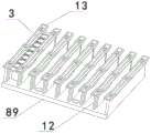
The diagnosis device in the embodiment of the present application may be described as follows by taking a fully automatic laser-activated chemiluminescence detector as an example, and then, the structure of the fully automatic laser-activated chemiluminescence detector is described as follows with reference to fig. 1, fig. 2, fig. 3, and fig. 4.
As shown in fig. 1, 2, 3 and 4, the fully automatic light-activated chemiluminescence detector may include: the device comprises a plate taking frame module 83, a pushing device 84, a sample adding arm module 4, a sample adding module 85, a sample frame module 86, an incubation module 87, a reagent module 5 and a detection module 88, wherein the plate strip 3 on the plate taking frame module 83 is pushed to the sample adding module 85 through the pushing device 84, a sample and a reagent are added into a reaction cup on the plate strip on the sample adding module 85 through the sample adding arm module 4, the plate strip on the sample adding module 85 is pushed into the incubation module 87 through the pushing device 84, and the plate strip enters the detection module 88 for detection after the incubation is finished.
Get the frame module 83 and locate the front portion of frame 2, be equipped with shell 1 in frame 2 outside, the carousel is located the rear of getting frame module 83, temperature culture module 87 is located carousel one side, sample frame module 86 and reagent module 5 are located the both sides of getting frame module 83 respectively, pusher 84 includes X to push mechanism 6 and Y to push mechanism 7, it pushes to carousel 19 through Y to push mechanism 7 to get the lath on the frame module 83, lath 3 on the carousel 19 passes through X to push mechanism 6 and gets into temperature culture module 87, get into detection module 88 after the temperature culture finishes and detect.
The incubation module 87 comprises an incubation plate 8 and a first slide mechanism by which the incubation plate 8 is slidably connected to the frame 2, the incubation plate 8 being provided with a slat clamping device 90.
The incubation module 87 comprises two incubation plates 8 arranged in parallel, and the two incubation plates are respectively connected with the frame 2 in a sliding manner through a set of first sliding mechanism, the first sliding mechanism comprises a first motor 9 and a first sliding rail 10, the incubation plates 8 are arranged on the first sliding rail 10, the first motor 9 is connected with the incubation plates 8 through a first synchronous belt 11, and the first motor 9 rotates to drive the incubation plates 8 to slide along the first sliding rail 10.
The incubation is divided into two incubation plates 87 to be respectively carried out, different times of incubation can be respectively realized, and the speed of the incubation plate 8 moving back and forth can be determined by the rotation speed of the first motor 9, so that the oscillation mixing in different degrees can be realized, and the operation is more flexible and changeable.
Next, the test method provided in the present application will be described in detail with reference to specific examples.
Referring to fig. 5, a flowchart illustrating steps of a testing method provided in an embodiment of the present application is shown, where the testing method may be applied to a diagnostic device or a terminal connected to the diagnostic device, and specifically includes the following steps:
step 101: and obtaining a test result signal value corresponding to the test item of the sample test solution.
In this embodiment of the application, the terminal may be a mobile electronic Device such as a mobile phone and a PAD (Portable Android Device), and may also be a Personal Computer (PC) terminal such as a desktop Computer and a notebook Computer, and specifically, may be determined according to a service requirement, which is not limited in this embodiment of the application.
The diagnostic device may be a device used in medical diagnosis or testing, including but not limited to: biochemical analyzer, chemiluminescence immunity analyzer, fluorescence immunity analyzer, immune turbidimetry analyzer, biochemical immunity integrated machine and gene sequencer. This embodiment is described in detail with a fully automatic light-activated chemiluminescent detector.
The communication connection is pre-established between the terminal and the full-automatic light-activated chemiluminescence detector, specifically, the terminal CAN be connected with the full-automatic light-activated chemiluminescence detector through a Controller Area Network (CAN) or a Network cable, and the CAN bus is connected through a serial data line through a CAN bus, a sensor, a Controller and an actuator. The network can detect and correct data errors caused by electromagnetic interference in the data transmission process according to the protocol, and the communication protocol of the network is equivalent to a data link layer in an ISO/OSI reference model.
After the terminal and the full-automatic light-activated chemical light-emitting detector are in communication connection through the CAN bus, data interaction between the terminal and the full-automatic light-activated chemical light-emitting detector CAN be realized.
The sample test solution refers to a test solution of a test user, and the sample test solution may be a test solution of blood, urine, or the like, specifically, the sample test solution may be determined according to a business requirement, which is not limited in this embodiment of the present application.
The test items refer to items which the test user needs to test, such as five items of hepatitis B and the like.
The diagnostic device is provided with a test module, for example, when the diagnostic device is a full-automatic light-activated chemiluminescence detector, the test module is the test module 88, a test line of the sample test solution can be tested by the test module, the test module tests the sample test solution, and the obtained signal value of the test item is a test result signal value.
The test procedure for the test items may be described in detail in connection with the following specific implementation.
In a specific implementation manner of the present application, the step 101 may include:
substep A1: and according to the test item, sucking a set amount of sample test solution and a test reagent corresponding to the sample test solution.
In the embodiment of the present application, the set amount refers to the amount of the sample test solution and the test reagent which are drawn when the test item of the test user is tested, which is preset by the service staff.
After the test item of the test user is obtained, a set amount of sample test solution of the test user and a test reagent corresponding to the sample test solution can be sucked according to the test item.
After the set amount of the sample test solution and the test reagent corresponding to the sample test solution are sucked according to the test item, sub-step a2 is performed.
Substep A2: and testing the set amount of sample testing solution and the testing reagent through a testing module of the diagnostic equipment to obtain a testing result signal value.
After the set amount of sample test solution and the test reagent corresponding to the sample test solution are sucked, the set amount of sample test solution and the test reagent can be tested through a test module on the diagnostic equipment, so that a test result signal value can be obtained.
After obtaining the test result signal value corresponding to the test item of the sample test solution, step 102 is executed.
Step 102: and converting the test result signal value into a test result data value.
The test result data value is a data value obtained by converting the test result signal value.
After the test result signal value is obtained, the test result signal value may be converted to obtain a test result data value corresponding to the test item. Specifically, the test result signal value may be converted into the test result data value according to a scaling index corresponding to a preset test item.
In the terminal system, a corresponding scaling index is preset for each test item, and a specific value of the scaling index may be determined according to an actual situation, which is not limited in the embodiment of the present application.
After obtaining the test result signal value, first, a calibration index corresponding to the test item may be obtained, and a test result data value may be obtained by calculation in combination with the calibration index, specifically, the test result signal value × the calibration index may be equal to the test result data value.
After converting the test result signal values into test result data values, step 103 is performed.
Step 103: and when the data value of the test result is determined to be abnormal, obtaining the liquid to be tested again according to the test item and the sample test liquid.
After the test result data value corresponding to the test result signal value is obtained, whether the test result data value is abnormal or not may be determined, specifically, when the test result data value is too large or too small, the test result may be abnormal due to the test abnormality, and the obtained test result data value is the abnormal data value.
The liquid to be tested refers to the test liquid obtained when the test item of the test user is tested again, and the liquid to be tested can simultaneously contain the sample test liquid and the test reagent of the test user.
When it is determined that the test result data value is abnormal, the fluid to be tested may be obtained again according to the test item and the sample test fluid, and specifically, the following specific implementation manner may be described in detail.
In a specific implementation manner of the present application, the step 103 may include:
substep B1: and when the data value of the test result is determined to be abnormal, adding a set amount of sample test solution and a test reagent again according to the test item to obtain the solution to be tested.
In the embodiment of the application, when the data value of the test result is determined to be abnormal, a set amount of sample test solution and a test reagent can be added into the reaction cup again according to the test item, so that the solution to be tested can be obtained.
After the fluid to be tested is retrieved based on the test item and the sample test fluid, step 104 is performed.
Step 104: and testing the liquid to be tested again.
After the liquid to be tested is obtained, the liquid to be tested can be tested again, specifically, the liquid to be tested can be tested through the testing module on the diagnostic equipment, so that a signal value of a testing result of the retest can be obtained, then, the signal value of the testing result is converted into a data value of the testing result by combining with the calibration index corresponding to the testing item, and whether the data value of the testing result is abnormal or not is judged.
And when the data value of the test result obtained by retesting is judged to be the normal data value, the test item of the test user is shown to be finished.
And when the data value of the test result obtained by retesting is judged to be an abnormal data value, the test is abnormal, and then the liquid to be tested of the test item of the test user can be obtained again, the next test process is carried out, and the like until the obtained data value of the test result is normal.
According to the embodiment of the application, manual management control is not required to be arranged, the liquid to be tested can be directly obtained to be tested for retesting when the test result is abnormal, a professional is not required to determine the abnormal result, and the test time is saved.
According to the test method provided by the embodiment of the application, the test result signal is converted into the test result data value by obtaining the test result signal value corresponding to the test item of the sample test solution, and when the test result data value is determined to be abnormal, the liquid to be tested is obtained again according to the test item and the sample test solution, and the liquid to be tested is tested again. According to the embodiment of the application, manual management control is not required to be arranged, the liquid to be tested can be directly obtained to be tested for retesting when the test result is abnormal, a professional is not required to determine the abnormal result, and the test time is saved.
While, for purposes of simplicity of explanation, the foregoing method embodiments have been described as a series of acts or combination of acts, it will be appreciated by those skilled in the art that the present application is not limited by the order of acts or acts described, as some steps may occur in other orders or concurrently with other steps in accordance with the application. Further, those skilled in the art should also appreciate that the embodiments described in the specification are preferred embodiments and that the acts and modules referred to are not necessarily required in this application.
Referring to fig. 6, a schematic structural diagram of a testing apparatus provided in an embodiment of the present application is shown, where the testing apparatus may be applied to a diagnostic device or a terminal connected to the diagnostic device, and specifically includes the following modules:
a signal value obtaining module 210, configured to obtain a test result signal value corresponding to a test item of the sample test solution;
a data value conversion module 220, configured to convert the test result signal value into a test result data value;
the to-be-tested liquid acquisition module 230 is configured to, when it is determined that the test result data value is abnormal, reacquire the to-be-tested liquid according to the test item and the sample test liquid;
and the test module 240 for the liquid to be tested is used for testing the liquid to be tested again.
Optionally, the signal value obtaining module 210 includes:
the test reagent sucking submodule is used for sucking a set amount of sample test solution and a test reagent corresponding to the sample test solution according to the test item;
and the signal value acquisition sub-module is used for testing the set amount of sample test solution and the test reagent through a test module of the diagnostic equipment to obtain a test result signal value.
Optionally, the data value conversion module 220 includes:
and the data value conversion submodule is used for converting the test result signal value into the test result data value according to the scaling index corresponding to the test item.
Optionally, the test solution obtaining module 230 includes:
and the to-be-tested liquid acquisition submodule is used for adding a set amount of sample test liquid and a test reagent again according to the test item when the test result data value is determined to be abnormal, so as to obtain the to-be-tested liquid.
Optionally, the terminal establishes a connection with the diagnostic device through a controller area network bus.
The test device provided by the embodiment of the application converts the test result signal into the test result data value by obtaining the test result signal value corresponding to the test item of the sample test solution, and obtains the solution to be tested again according to the test item and the sample test solution when determining that the test result data value is abnormal, and tests the solution to be tested again. According to the embodiment of the application, manual management control is not required to be arranged, the liquid to be tested can be directly obtained to be tested for retesting when the test result is abnormal, a professional is not required to determine the abnormal result, and the test time is saved.
Additionally, an embodiment of the present application further provides an electronic device, including: a processor, a memory and a computer program stored on the memory and executable on the processor, the processor implementing the above-described test method when executing the program.
Embodiments of the present application further provide a computer-readable storage medium, on which a computer program is stored, and when the computer program is executed by a processor, the computer program implements the testing method.
The embodiments in the present specification are described in a progressive manner, each embodiment focuses on differences from other embodiments, and the same and similar parts among the embodiments are referred to each other.
Finally, it should also be noted that, herein, relational terms such as first and second, and the like may be used solely to distinguish one entity or action from another entity or action without necessarily requiring or implying any actual such relationship or order between such entities or actions. Also, the terms "comprises," "comprising," or any other variation thereof, are intended to cover a non-exclusive inclusion, such that a process, method, article, or apparatus that comprises a list of elements does not include only those elements but may include other elements not expressly listed or inherent to such process, method, article, or apparatus. Without further limitation, an element defined by the phrase "comprising an … …" does not exclude the presence of other like elements in a process, method, article, or apparatus that comprises the element.
The above detailed description is provided for a testing method and a testing apparatus provided by the present application, and the principle and the implementation of the present application are explained by applying specific examples, and the description of the above examples is only used to help understanding the method and the core idea of the present application; meanwhile, for a person skilled in the art, according to the idea of the present application, there may be variations in the specific embodiments and the application scope, and in summary, the content of the present specification should not be construed as a limitation to the present application.