CN113118918B - Deformation grinding and polishing millstone based on thermoplastic material - Google Patents
Deformation grinding and polishing millstone based on thermoplastic material Download PDFInfo
- Publication number
- CN113118918B CN113118918B CN201911401657.8A CN201911401657A CN113118918B CN 113118918 B CN113118918 B CN 113118918B CN 201911401657 A CN201911401657 A CN 201911401657A CN 113118918 B CN113118918 B CN 113118918B
- Authority
- CN
- China
- Prior art keywords
- grinding
- polishing
- thermoplastic material
- deformation
- flexible layer
- Prior art date
- Legal status (The legal status is an assumption and is not a legal conclusion. Google has not performed a legal analysis and makes no representation as to the accuracy of the status listed.)
- Active
Links
Images


Classifications
-
- B—PERFORMING OPERATIONS; TRANSPORTING
- B24—GRINDING; POLISHING
- B24B—MACHINES, DEVICES, OR PROCESSES FOR GRINDING OR POLISHING; DRESSING OR CONDITIONING OF ABRADING SURFACES; FEEDING OF GRINDING, POLISHING, OR LAPPING AGENTS
- B24B13/00—Machines or devices designed for grinding or polishing optical surfaces on lenses or surfaces of similar shape on other work; Accessories therefor
- B24B13/01—Specific tools, e.g. bowl-like; Production, dressing or fastening of these tools
- B24B13/012—Specific tools, e.g. bowl-like; Production, dressing or fastening of these tools conformable in shape to the optical surface, e.g. by fluid pressure acting on an elastic membrane
-
- B—PERFORMING OPERATIONS; TRANSPORTING
- B24—GRINDING; POLISHING
- B24B—MACHINES, DEVICES, OR PROCESSES FOR GRINDING OR POLISHING; DRESSING OR CONDITIONING OF ABRADING SURFACES; FEEDING OF GRINDING, POLISHING, OR LAPPING AGENTS
- B24B37/00—Lapping machines or devices; Accessories
- B24B37/11—Lapping tools
Landscapes
- Engineering & Computer Science (AREA)
- Mechanical Engineering (AREA)
- Physics & Mathematics (AREA)
- Fluid Mechanics (AREA)
- Grinding And Polishing Of Tertiary Curved Surfaces And Surfaces With Complex Shapes (AREA)
- Polishing Bodies And Polishing Tools (AREA)
Abstract
本发明提供一种基于热塑性材料的变形研抛磨盘,通过在研抛磨盘结构中加入硬度随着温度升高而降低的柔性层,使研抛磨盘具备一定变形能力,在加工非球面光学元件过程中能够保证研抛磨盘的加工面与非球面光学元件的球面保持吻合,提高了材料去除的稳定性,因此可以增大研抛磨盘的变形基板直径尺寸,使得非球面光学加工过程中能够应用更大口径研抛盘,提高加工效率;同时,采用硬度随着温度升高而降低的热塑性材料制作柔性层,通过加热电加热片从而改变研抛磨盘的温度进而控制研抛磨盘的整体刚度,使研抛磨盘兼具面形误差去除和平滑作用,提高了研抛磨盘的适用范围,并且还具有结构较为简单,成本较低的优点。
The invention provides a deformable grinding disc based on thermoplastic material. By adding a flexible layer whose hardness decreases with the increase of temperature in the structure of the grinding disc, the grinding disc has a certain deformability, and can be used in the process of processing aspherical optical elements. It can ensure that the processing surface of the polishing disc and the spherical surface of the aspherical optical element are consistent, and improve the stability of material removal, so the diameter of the deformed substrate of the polishing disc can be increased, so that the aspherical optical processing can be applied. Large-diameter grinding and polishing discs improve processing efficiency; at the same time, the flexible layer is made of thermoplastic materials whose hardness decreases with increasing temperature, and the temperature of the grinding and polishing discs is changed by heating the electric heating sheet to control the overall rigidity of the grinding and polishing discs. The polishing disc has the functions of surface shape error removal and smoothing, which improves the application range of the polishing disc, and also has the advantages of simple structure and low cost.
Description
技术领域technical field
本发明属于光学器件加工技术领域,尤其涉及一种基于热塑性材料的变形研抛磨盘。The invention belongs to the technical field of optical device processing, and in particular relates to a deformation grinding and polishing disc based on thermoplastic materials.
背景技术Background technique
用非球面可以有效提升光学系统成像质量,简化系统结构,因此在现代光学系统中,非球面光学元件得到了广泛的应用。与球面或平面光学元件相比,非球面光学元件表面各点曲率都不相同,大尺寸刚性研抛盘无法与变化的非球面表面曲率相适应,因此无法满足非球面光学元件加工需求。目前,主要的非球面光学元件加工方法是采用计算机控制小研抛盘的计算机表面成型技术。该方法通常使用尺寸远小于非球面光学元件尺寸的研抛盘进行加工。这种方法通过减小研抛盘尺寸提高其与非球面表面吻合度,但是由于减小了研抛盘尺寸,因此材料去除效率大幅降低。无法满足非球面光学元件高效率加工需求。The use of aspherical surfaces can effectively improve the imaging quality of the optical system and simplify the system structure. Therefore, in modern optical systems, aspherical optical components have been widely used. Compared with spherical or flat optical elements, the curvature of each point on the surface of aspheric optical elements is different, and the large-sized rigid polishing disc cannot adapt to the changing curvature of the aspheric surface, so it cannot meet the processing requirements of aspheric optical elements. At present, the main processing method of aspherical optical components is the computer surface forming technology using computer-controlled small grinding and polishing discs. This method is typically processed using lapping disks that are much smaller in size than aspheric optics. This method improves the fit with the aspheric surface by reducing the size of the polishing disk, but the material removal efficiency is greatly reduced due to the reduced size of the polishing disk. It cannot meet the high-efficiency processing requirements of aspheric optical components.
现有技术中,为解决大尺寸研抛盘与镜面吻合问题而提出的是应力盘加工技术,其中,应力盘基本原理如图1所示,该技术通过使用力驱动器调节应力盘面形以达到研抛盘表面与非球面表面吻合的目的。由于应力盘背部必须使用力驱动器或相近的结构进行变形控制,需要额外加入控制系统,因此结构较为复杂。而且由于应力盘背部需要安装变形控制系统,研抛盘必须大于一定尺寸,因此很难制作小尺寸研抛盘,对于面形误差尺度较小的面形误差控制能力也较差,不适于加工中小口径非球面光学元件。In the prior art, in order to solve the problem of matching the large-size polishing disk with the mirror surface, the stress disk processing technology is proposed. The basic principle of the stress disk is shown in Figure 1. This technology adjusts the surface shape of the stress disk by using a force driver to achieve the polishing disk. The purpose for which the surface matches the aspherical surface. Since the back of the stress disk must use a force driver or a similar structure for deformation control, an additional control system needs to be added, so the structure is more complicated. Moreover, since a deformation control system needs to be installed on the back of the stress disk, the grinding and polishing disk must be larger than a certain size, so it is difficult to make a small-sized grinding and polishing disk. Spherical optics.
美国亚利桑那大学提出了另一种解决方案为非牛顿体研抛盘。该技术是在研抛盘中加入一种非牛顿体材料。非牛顿体是指不满足牛顿黏性实验定律的流体,即其剪应力与剪切应变率之间不是线性关系的流体。非牛顿体研抛盘使用搞得非牛顿体特性为:在瞬时力作用下,该材料表现出刚性,不易变形。在长时间力作用下该材料表现出柔性,可在力的作用下缓慢变形。通过该作用,使非牛顿体研抛盘兼具刚性研抛盘与柔性研抛盘特性,使研抛盘在非球面表面研抛过程中产生变形,从而满足吻合需求。该方法的问题是在加工过程中变形特性完全由非牛顿体提供,该性质无法根据不同非球面曲率进行改变,无法主动调节刚度和柔性。而通常情况下,针对不同陡度的非球面表面,其对磨头柔性要求不同。对于高陡度,曲率变化较大非球面表面要求柔性较高,对于低陡度,曲率变化较小的飞球面表面,对刚性要求较高,因此,同一个非牛顿体研抛的通用性较差。另外,由于非牛顿体本身变形特性,在非球面边缘处非牛顿体研抛盘探出镜面时,其非牛顿体会使研抛盘表面变形,可能导致边缘处产生较大的材料去除,形成塌边。Another solution proposed by the University of Arizona is a non-Newtonian disc. The technique involves adding a non-Newtonian material to the disc. A non-Newtonian body refers to a fluid that does not satisfy Newton's experimental law of viscosity, that is, a fluid whose shear stress and shear strain rate are not linearly related. The use of non-Newtonian grinding and throwing discs makes the non-Newtonian characteristics: under the action of instantaneous force, the material exhibits rigidity and is not easily deformed. The material exhibits flexibility under prolonged force and can slowly deform under force. Through this function, the non-Newtonian grinding and polishing disk has the characteristics of both rigid grinding and polishing disk and flexible grinding and polishing disk, so that the grinding and polishing disk is deformed during the grinding and polishing process of the aspheric surface, so as to meet the matching requirements. The problem with this method is that the deformation characteristics are completely provided by non-Newtonian bodies during processing, which cannot be changed according to different aspheric curvatures, and cannot actively adjust stiffness and flexibility. In general, for aspheric surfaces with different steepness, the requirements for the flexibility of the grinding head are different. For high steepness, the aspheric surface with large curvature change requires higher flexibility, and for low steepness, the flying spherical surface with small curvature change requires higher rigidity. Therefore, the same non-Newtonian body is more versatile in grinding and polishing. Difference. In addition, due to the deformation characteristics of the non-Newtonian body itself, when the non-Newtonian polishing disk protrudes from the mirror surface at the edge of the aspheric surface, the non-Newtonian body will deform the surface of the polishing disk, which may lead to large material removal at the edge, resulting in a slump.
发明内容SUMMARY OF THE INVENTION
为解决上述问题,本发明提供一种基于热塑性材料的变形研抛磨盘,具备一定变形能力,在加工非球面光学元件过程中能够保证研抛磨盘的加工面与非球面光学元件的球面保持吻合,提高了材料去除的稳定性,使得非球面光学加工过程中能够应用更大口径研抛磨盘,提高加工效率。In order to solve the above-mentioned problems, the present invention provides a deformation grinding disc based on thermoplastic material, which has a certain deformability, and can ensure that the processing surface of the grinding disc and the spherical surface of the aspheric optical element are kept consistent in the process of processing the aspheric optical element. The stability of material removal is improved, so that a larger diameter grinding and polishing disc can be used in the process of aspheric optical processing, and the processing efficiency is improved.
一种基于热塑性材料的变形研抛磨盘,包括两个以上的电加热片1、数控电源2以及均为圆盘结构且尺寸相同的刚性基底3、柔性层4、变形基板5;A deformation grinding and polishing disc based on thermoplastic material, comprising more than two electric heating sheets 1, a numerically controlled power supply 2, a
所述电加热片1布置在刚性基底3上;同时,刚性基底3的下方依次铺设柔性层4与变形基板5,其中,柔性层4的硬度随着温度升高而降低,变形基板5的下表面用于粘接研抛磨材料层;The electric heating sheet 1 is arranged on the
所述数控电源2用于为电加热片1供电。The numerical control power supply 2 is used to supply power to the electric heating plate 1 .
进一步地,一种基于热塑性材料的变形研抛磨盘,还包括密封圈6;Further, a deformation grinding and polishing disc based on thermoplastic material, further comprising a sealing ring 6;
所述密封圈6设置于刚性基底3、柔性层4以及变形基板5的外侧用于对三者的外沿进行密封。The sealing ring 6 is disposed on the outer sides of the
进一步地,所述刚性基底3上表面中心处设置有带螺纹的凹槽,所述凹槽用于连接所述变形研抛磨盘与外部数控机床。Further, a threaded groove is provided at the center of the upper surface of the
进一步地,所述刚性基底3的材质为金属。Further, the material of the
进一步地,所述刚性基底3的材质为铝。Further, the material of the
进一步地,所述柔性层4为热塑性材料。Further, the flexible layer 4 is a thermoplastic material.
进一步地,所述柔性层4为淀粉基塑料。Further, the flexible layer 4 is a starch-based plastic.
进一步地,所述变形基板5材质为铝。Further, the deformed substrate 5 is made of aluminum.
进一步地,所述变形基板5材质为尼龙。Further, the deformation substrate 5 is made of nylon.
有益效果:Beneficial effects:
本发明提供一种基于热塑性材料的变形研抛磨盘,通过在研抛磨盘结构中加入硬度随着温度升高而降低的柔性层,使研抛磨盘具备一定变形能力,在加工非球面光学元件过程中能够保证研抛磨盘的加工面与非球面光学元件的球面保持吻合,提高了材料去除的稳定性,因此可以增大研抛磨盘的变形基板直径尺寸,使得非球面光学加工过程中能够应用更大口径研抛盘,提高加工效率;同时,采用硬度随着温度升高而降低的热塑性材料制作柔性层,通过加热电加热片从而改变研抛磨盘的温度进而控制研抛磨盘的整体刚度,使研抛磨盘兼具面形误差去除和平滑作用,提高了研抛磨盘的适用范围,并且还具有结构较为简单,成本较低的优点。The invention provides a deformable polishing disc based on thermoplastic material. By adding a flexible layer whose hardness decreases with the increase of temperature in the structure of the polishing disc, the polishing disc has a certain deformability, and can be used in the process of processing aspherical optical elements. It can ensure that the processing surface of the polishing disc and the spherical surface of the aspherical optical element are consistent, and improve the stability of material removal, so the diameter of the deformed substrate of the polishing disc can be increased, so that the aspherical optical processing can be applied. Large-caliber grinding and polishing discs improve processing efficiency; at the same time, the flexible layer is made of thermoplastic materials whose hardness decreases with increasing temperature, and the temperature of the grinding and polishing discs is changed by heating the electric heating sheet to control the overall rigidity of the grinding and polishing discs. The polishing disc has the functions of surface shape error removal and smoothing, which improves the application range of the polishing disc, and also has the advantages of simple structure and low cost.
附图说明Description of drawings
图1为现有的应力盘的基本原理示意图;Fig. 1 is the basic principle schematic diagram of the existing stress disk;
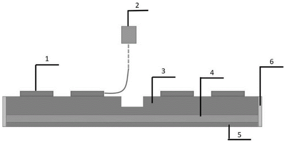
图2为本发明提供的基于热塑性材料的变形研抛磨盘的剖面示意图;Fig. 2 is the sectional schematic diagram of the deformation grinding disc based on thermoplastic material provided by the present invention;
图3为本发明提供的基于热塑性材料的变形研抛磨盘的圆盘结构的俯视图;Fig. 3 is the top view of the disc structure of the thermoplastic material-based deformation grinding disc provided by the present invention;
1-电加热片、2-数控电源、3-刚性基底、4-柔性层、5-变形基板、6-密封圈。1-Electric heating plate, 2-CNC power supply, 3-Rigid base, 4-Flexible layer, 5-Deformed substrate, 6-Sealing ring.
具体实施方式Detailed ways
为了使本技术领域的人员更好地理解本申请方案,下面将结合本申请实施例中的附图,对本申请实施例中的技术方案进行清楚、完整地描述。In order to make those skilled in the art better understand the solutions of the present application, the following will clearly and completely describe the technical solutions in the embodiments of the present application with reference to the accompanying drawings in the embodiments of the present application.
参见图2,该图为本实施例提供的一种基于热塑性材料的变形研抛磨盘的剖面示意图。一种基于热塑性材料的变形研抛磨盘,包括两个以上的电加热片1、数控电源2、密封圈6以及尺寸相同且均为圆盘结构的刚性基底3、柔性层4、变形基板5;Referring to FIG. 2 , this figure is a schematic cross-sectional view of a thermoplastic material-based deformed grinding disc provided in this embodiment. A deformation grinding and polishing disc based on thermoplastic material, comprising two or more electric heating sheets 1, a numerical control power supply 2, a sealing ring 6, and a
所述电加热片1均匀布置在刚性基底3上,并对刚性基底3进行加热;同时,刚性基底3的下方依次铺设柔性层4与变形基板5,其中,柔性层4的硬度随着温度升高而降低,变形基板5的下表面用于粘接研抛磨材料层;所述刚性基底3上表面中心处设置有带螺纹的凹槽,所述凹槽用于连接所述变形研抛磨盘与外部数控机床。The electric heating sheet 1 is evenly arranged on the
所述数控电源2用于为电加热片1供电。可选的,所述数控电源2为机床主轴预留接口,主轴内部通过滑环结构保证变形研抛磨盘旋转过程中数控电源电线不会发生缠绕。The numerical control power supply 2 is used to supply power to the electric heating plate 1 . Optionally, the numerical control power supply 2 reserves an interface for the main shaft of the machine tool, and a slip ring structure is used inside the main shaft to ensure that the numerical control power supply wires will not be entangled during the rotation of the deformed grinding and polishing disc.
所述密封圈6设置于刚性基底3、柔性层4以及变形基板5的外侧用于对三者的外沿进行密封,从而包裹整个变形研抛磨盘,避免柔性材料的露出。The sealing ring 6 is arranged on the outer sides of the
可选的,所述刚性基底3的材质为导热性良好的金属,如铝板。Optionally, the material of the
变形基板5另一面粘接的研抛磨材料层可以为抛光革或者其他研抛磨材料。The polishing material layer adhered to the other side of the deformed substrate 5 may be polished leather or other polishing materials.
可选的,所述柔性层4为热塑性材料,热塑性材料的材料性质是随温度升高材料硬度降低并具有一定变形能力,在温度降低后材料硬度恢复,优选淀粉基塑料,例如可以选用INPD3淀粉塑料,则柔性层4使研抛磨盘具备一定变形能力。Optionally, the flexible layer 4 is a thermoplastic material, and the material properties of the thermoplastic material are that the hardness of the material decreases with the increase of temperature and has a certain deformability, and the hardness of the material recovers after the temperature decreases, preferably starch-based plastics, for example, INPD3 starch can be selected. If it is plastic, the flexible layer 4 enables the polishing disc to have a certain deformability.
变形基板5要求其本身具备一定刚性,但是在压力作用下可以产生变形,具体材料选择、厚度由被加工非球面陡度以及研抛磨盘尺寸决定。变形基板5的材质优选铝或尼龙薄板,变形基板5的一面为平面,与柔性层4接触连接,另一面可以在压力作用下可以产生变形,变为与被加工非球面相接触的球面曲率一致的球面,与变形基板5粘接的研抛磨材料层也随之变为与被加工非球面相接触的球面曲率一致的球面,提高了材料加工去除的稳定性。The deformable substrate 5 requires itself to have a certain rigidity, but can be deformed under the action of pressure. The specific material selection and thickness are determined by the steepness of the processed aspheric surface and the size of the polishing disc. The material of the deformation substrate 5 is preferably aluminum or nylon sheet. One side of the deformation substrate 5 is flat and is in contact with the flexible layer 4. The other side can be deformed under the action of pressure, and the curvature of the spherical surface in contact with the processed aspheric surface is consistent. the spherical surface, the polishing material layer bonded to the deformed substrate 5 also becomes a spherical surface with the same curvature as the spherical surface in contact with the aspherical surface to be processed, which improves the stability of material processing and removal.
可选的,所述电加热片1的参数、数量及排列方式由所述柔性层4的材料性质及厚度、所述基于热塑性材料的变形研抛磨盘的变形基板5尺寸、被加工非球面的陡度决定。Optionally, the parameters, quantity and arrangement of the electric heating sheets 1 are determined by the material properties and thickness of the flexible layer 4, the size of the deformed substrate 5 of the thermoplastic material-based deformed polishing disc, the size of the processed aspheric surface. Steep decision.
可选的,所述电加热片1为PTC加热片,加热温度设置为80℃,额定电压为220V,功率为2-10W。Optionally, the electric heating sheet 1 is a PTC heating sheet, the heating temperature is set to 80° C., the rated voltage is 220V, and the power is 2-10W.
电加热片1可以通过机床预留导线与数控电源2相连,电加热片2的参数、数量及排列方式由柔性层4的材料性质及厚度、基于热塑性材料的变形研抛磨盘的变形基板5尺寸、被加工非球面的陡度决定,使得研抛磨盘能够均匀升温。如图2所述为本发明基于热塑性材料的变形研抛磨盘的结构的俯视图,在本实施例中,基于热塑性材料的变形研抛磨盘的变形基板5直径为300mm,柔性层4的材质为淀粉基塑料,该材料在温度达到50℃后开始变软,达到80℃时变为柔性材料,因此在本实施例中选择的是加热温度为80℃,额定电压220V,功率为2-10W的PTC加热片1,也就是说,只要为该PTC加热片通电,PTC加热器就能逐渐上升到80℃,如果需要其他加热温度,选用另一种规格的PTC加热片即可;如图3所示,PTC加热片1的数量为12个,沿径向由内向外均匀分布粘贴于刚性基底3的上方,使刚性基底3能均匀受热。The electric heating plate 1 can be connected to the numerical control power supply 2 through the reserved wire of the machine tool. The parameters, quantity and arrangement of the electric heating plate 2 are determined by the material properties and thickness of the flexible layer 4, and the size of the deformation substrate 5 of the deformation polishing disc based on thermoplastic materials. , The steepness of the processed aspheric surface is determined, so that the grinding and polishing discs can heat up evenly. FIG. 2 is a top view of the structure of the deformable polishing disc based on thermoplastic material of the present invention. In this embodiment, the diameter of the deformed substrate 5 of the deformable polishing disc based on thermoplastic material is 300 mm, and the material of the flexible layer 4 is starch Base plastic, the material starts to soften when the temperature reaches 50 °C, and becomes a flexible material when it reaches 80 °C. Therefore, in this embodiment, a PTC with a heating temperature of 80 °C, a rated voltage of 220V, and a power of 2-10W is selected Heating sheet 1, that is to say, as long as the PTC heating sheet is energized, the PTC heater can gradually rise to 80°C. If other heating temperatures are required, another type of PTC heating sheet can be selected; as shown in Figure 3 , the number of PTC heating sheets 1 is 12, which are uniformly distributed and pasted on the
数控电源2控制电加热片1的加热,通过改变电加热片1的加热时间可以实现控制基于热塑性材料的变形研抛磨盘中刚性基底3的温度,柔性层4的温度分布从与刚性基底3的接触面至与变形基板5的接触面呈现梯度分布。因此,可以通过控制刚性基底3的温度可实现柔性层4刚度调节,从而使研抛磨盘变形,满足研抛磨盘与非球面光学元件的吻合性要求,使大口径研抛磨盘的使用变为可能,从而有效提高了加工效率。The numerical control power supply 2 controls the heating of the electric heating plate 1. By changing the heating time of the electric heating plate 1, the temperature of the
变形研抛磨盘的工作原理为:The working principle of the deformation grinding and polishing disc is as follows:
首先数控电源1的导线通过滑环安装在机床主轴上,给电加热片1供电;电加热片1升温,从而加热刚性基底3;通过热传递的作用,电加热片1的热量传导到柔性层4上,柔性层4的硬度随着温度升高而降低,使研抛磨盘具备一定变形能力,满足研抛磨盘与非球面光学元件的吻合性要求;变形基板5的一面为平面,与柔性层4接触连接,另一面可以在压力作用下可以产生变形,变为与被加工非球面相接触的球面曲率一致的球面,与变形基板5粘接的研抛磨材料层也随之变为与被加工非球面相接触的球面曲率一致的球面。First of all, the wire of the numerical control power supply 1 is installed on the main shaft of the machine tool through a slip ring, and supplies power to the electric heating plate 1; 4, the hardness of the flexible layer 4 decreases with the increase of temperature, so that the polishing disc has a certain deformation ability, which meets the requirement of conformity between the polishing disc and the aspherical optical element; one side of the deformable substrate 5 is flat, and the flexible layer 4 Contact connection, the other side can be deformed under the action of pressure, and becomes a spherical surface with the same curvature as the spherical surface in contact with the aspheric surface to be processed, and the polishing material layer bonded to the deformed substrate A spherical surface with the same curvature as the spherical surfaces in contact with the aspheric surfaces are processed.
当然,本发明还可有其他多种实施例,在不背离本发明精神及其实质的情况下,熟悉本领域的技术人员当然可根据本发明作出各种相应的改变和变形,但这些相应的改变和变形都应属于本发明所附的权利要求的保护范围。Of course, the present invention can also have other various embodiments. Without departing from the spirit and essence of the present invention, those skilled in the art can of course make various corresponding changes and deformations according to the present invention, but these corresponding Changes and deformations should belong to the protection scope of the appended claims of the present invention.
Claims (9)
Priority Applications (1)
| Application Number | Priority Date | Filing Date | Title |
|---|---|---|---|
| CN201911401657.8A CN113118918B (en) | 2019-12-31 | 2019-12-31 | Deformation grinding and polishing millstone based on thermoplastic material |
Applications Claiming Priority (1)
| Application Number | Priority Date | Filing Date | Title |
|---|---|---|---|
| CN201911401657.8A CN113118918B (en) | 2019-12-31 | 2019-12-31 | Deformation grinding and polishing millstone based on thermoplastic material |
Publications (2)
| Publication Number | Publication Date |
|---|---|
| CN113118918A CN113118918A (en) | 2021-07-16 |
| CN113118918B true CN113118918B (en) | 2022-05-27 |
Family
ID=76769012
Family Applications (1)
| Application Number | Title | Priority Date | Filing Date |
|---|---|---|---|
| CN201911401657.8A Active CN113118918B (en) | 2019-12-31 | 2019-12-31 | Deformation grinding and polishing millstone based on thermoplastic material |
Country Status (1)
| Country | Link |
|---|---|
| CN (1) | CN113118918B (en) |
Citations (7)
| Publication number | Priority date | Publication date | Assignee | Title |
|---|---|---|---|---|
| JP2001267275A (en) * | 2000-03-23 | 2001-09-28 | Toshiba Ceramics Co Ltd | Silicon wafer polishing equipment |
| CN1562571A (en) * | 2004-04-09 | 2005-01-12 | 清华大学 | Temperature controllable polishing tool |
| CN101272883A (en) * | 2005-09-22 | 2008-09-24 | 3M创新有限公司 | Conformable abrasive articles and methods of making and using same |
| JP2009297879A (en) * | 2008-06-17 | 2009-12-24 | Chugoku Sarin Kigyo Kofun Yugenkoshi | Polishing tool |
| CN102794718A (en) * | 2012-07-30 | 2012-11-28 | 中国人民解放军国防科学技术大学 | Flexible passive adaptation type fairing disc and flexible sandwich layer thereof and method for operating flexible passive adaptation type fairing discs |
| CN103072077A (en) * | 2013-01-29 | 2013-05-01 | 中国科学院长春光学精密机械与物理研究所 | Double-flexible self-adaptive polishing grinding head |
| EP2676772A2 (en) * | 2012-06-21 | 2013-12-25 | Design Technologies LLC | Surface treating device |
Family Cites Families (1)
| Publication number | Priority date | Publication date | Assignee | Title |
|---|---|---|---|---|
| US6706319B2 (en) * | 2001-12-05 | 2004-03-16 | Siemens Westinghouse Power Corporation | Mixed powder deposition of components for wear, erosion and abrasion resistant applications |
-
2019
- 2019-12-31 CN CN201911401657.8A patent/CN113118918B/en active Active
Patent Citations (7)
| Publication number | Priority date | Publication date | Assignee | Title |
|---|---|---|---|---|
| JP2001267275A (en) * | 2000-03-23 | 2001-09-28 | Toshiba Ceramics Co Ltd | Silicon wafer polishing equipment |
| CN1562571A (en) * | 2004-04-09 | 2005-01-12 | 清华大学 | Temperature controllable polishing tool |
| CN101272883A (en) * | 2005-09-22 | 2008-09-24 | 3M创新有限公司 | Conformable abrasive articles and methods of making and using same |
| JP2009297879A (en) * | 2008-06-17 | 2009-12-24 | Chugoku Sarin Kigyo Kofun Yugenkoshi | Polishing tool |
| EP2676772A2 (en) * | 2012-06-21 | 2013-12-25 | Design Technologies LLC | Surface treating device |
| CN102794718A (en) * | 2012-07-30 | 2012-11-28 | 中国人民解放军国防科学技术大学 | Flexible passive adaptation type fairing disc and flexible sandwich layer thereof and method for operating flexible passive adaptation type fairing discs |
| CN103072077A (en) * | 2013-01-29 | 2013-05-01 | 中国科学院长春光学精密机械与物理研究所 | Double-flexible self-adaptive polishing grinding head |
Also Published As
| Publication number | Publication date |
|---|---|
| CN113118918A (en) | 2021-07-16 |
Similar Documents
| Publication | Publication Date | Title |
|---|---|---|
| US8552347B2 (en) | Method and a device for bonding a metal fairing to the leading edge of an airfoil | |
| TWI421148B (en) | Radiator with grinding and heating plane and grinding method and equipment thereof | |
| KR20010108076A (en) | Apparatus and method for polishiing | |
| KR20080065612A (en) | How to bind superabrasive particles to organic matrix | |
| CN102139465A (en) | High-efficiency ultra-precision machining method for parts with aspheric curved surfaces and high-efficiency ultra-precision machining device therefor | |
| CN107671605A (en) | A kind of optical mirror slip burnishing device and glossing | |
| US20120040590A1 (en) | Non-newtonian lap | |
| KR102304521B1 (en) | Ultrasonic fingerprint recognition display protective film | |
| SG189227A1 (en) | Abrasive articles | |
| CN113118918B (en) | Deformation grinding and polishing millstone based on thermoplastic material | |
| JP2001291690A (en) | Apparatus and method for polishing | |
| JP2015039742A (en) | Polishing head and polishing apparatus | |
| TWI658968B (en) | Thermoplastic film method of three-dimensional surface device | |
| US20140273764A1 (en) | Lapping carrier having hard and soft properties, and methods | |
| CN102581748A (en) | Float disc feeding method for planar wafer optical parts | |
| CN110091249A (en) | The method for dismounting and heating device of a kind of installation method of grinding pad, grinding pad | |
| CN115351662A (en) | A manipulator for aeroengine blade normal position is polished | |
| CN111482337A (en) | A kind of ultra-thin part asphalt bonding method | |
| JP4303860B2 (en) | Silicon wafer polishing equipment | |
| TWI531443B (en) | A method for manufacturing an elastic film for a grinding head and a manufacturing apparatus | |
| CN211916462U (en) | A flexible gel grinding wheel processing platform | |
| US9242441B1 (en) | Heating device for use with a clamp for laminating substrates | |
| KR102695958B1 (en) | Retainer ring used in polishing apparatus | |
| JP2005333100A (en) | Support plate | |
| CN110246782B (en) | Thermal bonding head for COF packaging and preparation method thereof |
Legal Events
| Date | Code | Title | Description |
|---|---|---|---|
| PB01 | Publication | ||
| PB01 | Publication | ||
| SE01 | Entry into force of request for substantive examination | ||
| SE01 | Entry into force of request for substantive examination | ||
| GR01 | Patent grant | ||
| GR01 | Patent grant |