CN113110048B - Nonlinear system output feedback adaptive control system and method adopting HOSM observer - Google Patents
Nonlinear system output feedback adaptive control system and method adopting HOSM observer Download PDFInfo
- Publication number
- CN113110048B CN113110048B CN202110392290.9A CN202110392290A CN113110048B CN 113110048 B CN113110048 B CN 113110048B CN 202110392290 A CN202110392290 A CN 202110392290A CN 113110048 B CN113110048 B CN 113110048B
- Authority
- CN
- China
- Prior art keywords
- actuator
- output
- observer
- hosm
- unknown
- Prior art date
- Legal status (The legal status is an assumption and is not a legal conclusion. Google has not performed a legal analysis and makes no representation as to the accuracy of the status listed.)
- Active
Links
- 230000003044 adaptive effect Effects 0.000 title claims abstract description 59
- 238000000034 method Methods 0.000 title claims abstract description 35
- 238000013461 design Methods 0.000 claims abstract description 25
- 239000013598 vector Substances 0.000 claims description 30
- 230000006978 adaptation Effects 0.000 claims description 11
- 239000011159 matrix material Substances 0.000 claims description 11
- 238000009738 saturating Methods 0.000 claims description 9
- 238000004364 calculation method Methods 0.000 claims description 6
- 238000012986 modification Methods 0.000 claims description 6
- 238000009499 grossing Methods 0.000 claims description 5
- 239000004576 sand Substances 0.000 claims 1
- 230000001360 synchronised effect Effects 0.000 abstract 1
- 238000010586 diagram Methods 0.000 description 10
- 238000013459 approach Methods 0.000 description 4
- 238000010276 construction Methods 0.000 description 3
- 230000001276 controlling effect Effects 0.000 description 3
- 238000011160 research Methods 0.000 description 3
- 238000004088 simulation Methods 0.000 description 3
- 238000013528 artificial neural network Methods 0.000 description 2
- 238000012938 design process Methods 0.000 description 2
- 230000001965 increasing effect Effects 0.000 description 2
- 238000012886 linear function Methods 0.000 description 2
- 229920006395 saturated elastomer Polymers 0.000 description 2
- RZVHIXYEVGDQDX-UHFFFAOYSA-N 9,10-anthraquinone Chemical compound C1=CC=C2C(=O)C3=CC=CC=C3C(=O)C2=C1 RZVHIXYEVGDQDX-UHFFFAOYSA-N 0.000 description 1
- 241001504469 Anthus Species 0.000 description 1
- 238000012369 In process control Methods 0.000 description 1
- 229910000831 Steel Inorganic materials 0.000 description 1
- JXASPPWQHFOWPL-UHFFFAOYSA-N Tamarixin Natural products C1=C(O)C(OC)=CC=C1C1=C(OC2C(C(O)C(O)C(CO)O2)O)C(=O)C2=C(O)C=C(O)C=C2O1 JXASPPWQHFOWPL-UHFFFAOYSA-N 0.000 description 1
- 230000003190 augmentative effect Effects 0.000 description 1
- 238000002485 combustion reaction Methods 0.000 description 1
- 230000002596 correlated effect Effects 0.000 description 1
- 230000007812 deficiency Effects 0.000 description 1
- 230000000694 effects Effects 0.000 description 1
- 230000002708 enhancing effect Effects 0.000 description 1
- 238000001914 filtration Methods 0.000 description 1
- 239000012530 fluid Substances 0.000 description 1
- 238000010965 in-process control Methods 0.000 description 1
- 239000002184 metal Substances 0.000 description 1
- 239000000203 mixture Substances 0.000 description 1
- 230000010355 oscillation Effects 0.000 description 1
- 238000005096 rolling process Methods 0.000 description 1
- 239000010959 steel Substances 0.000 description 1
- 238000006467 substitution reaction Methods 0.000 description 1
- 238000012546 transfer Methods 0.000 description 1
- 230000001052 transient effect Effects 0.000 description 1
- XLYOFNOQVPJJNP-UHFFFAOYSA-N water Substances O XLYOFNOQVPJJNP-UHFFFAOYSA-N 0.000 description 1
Images


Classifications
-
- G—PHYSICS
- G05—CONTROLLING; REGULATING
- G05B—CONTROL OR REGULATING SYSTEMS IN GENERAL; FUNCTIONAL ELEMENTS OF SUCH SYSTEMS; MONITORING OR TESTING ARRANGEMENTS FOR SUCH SYSTEMS OR ELEMENTS
- G05B13/00—Adaptive control systems, i.e. systems automatically adjusting themselves to have a performance which is optimum according to some preassigned criterion
- G05B13/02—Adaptive control systems, i.e. systems automatically adjusting themselves to have a performance which is optimum according to some preassigned criterion electric
- G05B13/04—Adaptive control systems, i.e. systems automatically adjusting themselves to have a performance which is optimum according to some preassigned criterion electric involving the use of models or simulators
- G05B13/042—Adaptive control systems, i.e. systems automatically adjusting themselves to have a performance which is optimum according to some preassigned criterion electric involving the use of models or simulators in which a parameter or coefficient is automatically adjusted to optimise the performance
Landscapes
- Engineering & Computer Science (AREA)
- Health & Medical Sciences (AREA)
- Artificial Intelligence (AREA)
- Computer Vision & Pattern Recognition (AREA)
- Evolutionary Computation (AREA)
- Medical Informatics (AREA)
- Software Systems (AREA)
- Physics & Mathematics (AREA)
- General Physics & Mathematics (AREA)
- Automation & Control Theory (AREA)
- Feedback Control In General (AREA)
Abstract
The embodiment of the application provides a nonlinear system output feedback adaptive control system and method adopting an HOSM (hyper extended synchronous compensator) observer, and relates to the technical field of adaptive control. Aiming at a single-input single-output uncertain nonlinear system with actuator limitation, particularly under the conditions of control gain uncertainty and actuator speed limitation, the characteristics of an HOSM observer are utilized, and the unmeasured state of the system can be accurately estimated under the condition of only needing the output quantity of the observed system. The design of the controller can be easier due to the design of the relatively independent observer, and when the method is applied to the roll dynamic control of the delta wing aircraft, the self-adaptive adjusting capacity of the delta wing aircraft to the external environment and the robustness of a self-adaptive control system are improved.
Description
Technical Field
The application relates to the technical field of adaptive control, in particular to a nonlinear system output feedback adaptive control system and method adopting an HOSM observer.
Background
Currently, there have been many studies on adaptive output feedback control with input constraint systems. In general, these methods require the construction of an observer to estimate the non-measurable variables in the system, and then design adaptive controllers using the observer to address these difficulties in actual system control, in conjunction with methods that have been validated to handle input constraints. However, it is very difficult to design a good observer for a nonlinear system with uncertainty, and the method proposed in the prior art is complex in design and not easy to implement, and has the problem that adaptive adjustment is not accurate enough.
For example, for controlling the dynamics of a delta wing aircraft under a large attack angle condition, the currently adopted model reference adaptive control method needs all the states of a controlled system to be measurable, and is not an output feedback adaptive control method. In addition, many other output feedback adaptive control methods do not take into account the fact that the system has uncertainty in control gain when the system has actuator velocity limitations. This may result in poor adaptive tuning and robustness of the system control.
Disclosure of Invention
In view of the above, embodiments of the present application provide a nonlinear system output feedback adaptive control system and method using a HOSM observer to improve the above problem.
In a first aspect, the present application provides a nonlinear system output feedback adaptive control system using an HOSM observer, including a state observer using an HOSM, a dynamic system of an object to be controlled, an adaptive law, and a control law;
a single input single output nonlinear system with input actuator limitations is proposed:

v=sat(η(u))
where x (t) is the measurable output, φiIs a known non-linear smoothing function that satisfies the consistent Lipschitz condition, θiAs an unknown constant, bcFor unknown constant control gain, v is actuator output, d1 is a bounded slow time-varying disturbance, and u is the controller output signal. sat (-) and η (-) are the amplitude saturation function and the rate saturation function of the actuator, respectively, and are defined as:
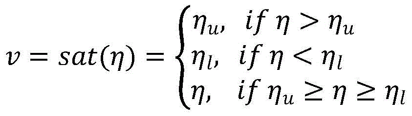

wherein eta isuAnd ηlSaturating the upper and lower limits for a known amplitude, and
and saturating the upper and lower limits for a known rate;
rewriting the nonlinear system with single input and single output limited by input actuators into the form of the following equation of state:


v=sat(η(u))
wherein, θ=[-θ1,-θ2,...-θr,d1]T,φ=[φ1,φ2,...,φr,1]T,x1being the only measurable output of the nonlinear system, bcFor unknown gain, v is the output of the actuator, u is the output signal of the controller, d1Is a bounded, slowly time-varying perturbation;
the state observer includes:


wherein, the 0 th time derivative of the time varying signal a (t),
 is the 1 st time derivative of the time varying signal a (t),
 is the n-1 order time derivative of the time varying signal a (t),
 is the nth order time derivative of the time-varying signal a (t), a (t) e [0, ∞), L, λ1...λnAre the HOSM observer parameters.
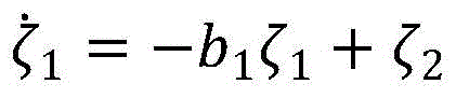
In an alternative embodiment, a dynamic system associated with the actuator saturation limit is configured for actuator saturation limits for the actuator, the dynamic system being driven by an actuator saturation error, the dynamic system generating a dynamic signal ζ for use in a subsequent controller design, the dynamic system comprising:
ζ=[ζ1,ζ2,...,ζn]T


wherein b isi1,2, n is an adjustable normal number, is an unknown gain bcIs updated by the adaptive law, Δ u is v-u, v is the output of the actuator, u is the output signal of the controller, and ζ is a dynamic signal having a correlation with the actuator saturation error.
In an alternative embodiment, the control law comprises:

wherein k is1> 0 is an optional normal number, for a vector of unknown parameters thetaTIs estimated by the estimation of (a) a,
 for estimation of the tracking error vector e, the tracking error vector
 Wherein,
 in order to track the error vector, zeta is the extended dynamic error term caused by actuator saturation deltau, where deltau is v-u, v is the output of the actuator, u is the output signal of the controller, and B is diag ([ B ] d)1,b2,…,bn]) Is a diagonal matrix, biN is an adjustable normal number, phi, 1,21,φ2,...,φr,1]T。
In an alternative embodiment, the estimation of the unknown parameter vector And estimation of unknown gain
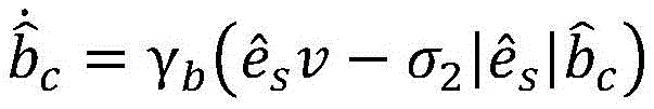
 The calculation is performed according to the following adaptation law:


wherein r ═ rT> 0 is a symmetric positive definite gain matrix, gammabA gain of a normal number > 0, σ1,σ2>0, And
And is the e-modification of the adaptation law.
In a second aspect, the present application provides a nonlinear system output feedback adaptive control method using a HOSM observer, comprising the steps of:
s1, a single input single output nonlinear system with input actuator constraints is proposed:

v=sat(η(u))
where x (t) is the measurable output, φiIs a known non-linear smoothing function that satisfies the consistent Lipschitz condition, θiAs an unknown constant, bcFor unknown constant control gain, v is actuator output, d1 is a bounded slow time-varying disturbance, and u is the controller output signal. sat (-) and η (-) are the amplitude saturation function and the rate saturation function of the actuator, respectively, and are defined as:
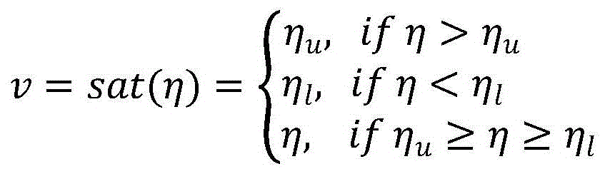

wherein eta isuAnd ηlSaturating the upper and lower limits for a known amplitude, and
and saturating the upper and lower limits for a known rate;
s2: the single input single output nonlinear system with input actuator limits is rewritten as the following equation of state form:


v=sat(η(u))
wherein, θ=[-θ1,-θ2,...-θr,d1]T,φ=[φ1,φ2,...,φr,1]T,x1being the only measurable output of said non-linear system, bcFor unknown gain, v is actuator output, u is controller output signal, d1Is a bounded, slowly time-varying perturbation;
s3: constructing a state observer adopting HOSM, a dynamic system of an object to be controlled, a self-adaptation law and a control law, wherein the state observer comprises:


wherein, the 0 th time derivative of the time varying signal a (t),
 is the 1 st time derivative of the time varying signal a (t),
 is the n-1 order time derivative of the time varying signal a (t),
 is the nth order time derivative of the time-varying signal a (t), a (t) e [0, ∞), L, λ1...λnAre the HOSM observer parameters.
In an alternative embodiment, a dynamic system associated with the actuator saturation limit is configured for actuator saturation limits of the actuator, the dynamic system being driven by actuator saturation errors, and generating dynamic signals for subsequent controller design, the dynamic system comprising:
ζ=[ζ1,ζ2,...,ζn]T


wherein b isi1,2, n is an adjustable normal number, is an unknown gain bcIs estimated value ofIn the adaptive law update, Δ u is v-u, v is an actuator output, u is a controller output signal, and ζ is a dynamic signal having a correlation with the actuator saturation error.
In an alternative embodiment, the control law comprises:

wherein k is1> 0 is an optional normal number, for a vector of unknown parameters thetaTIs estimated by the estimation of (a) a,
 for estimation of the tracking error vector e, the tracking error vector
 Wherein,
 for a conventional tracking error vector, - ζ is the extended dynamic error term caused by actuator saturation Δ u, Δ u being v-u, v being the actuator output, u being the controller output signal, B being diag ([ B)1,b2,…,bn]) Is a diagonal matrix, biN is an adjustable constant, phi is 1,21,φ2,...,φr,1]T。
In an alternative embodiment, the estimation of the unknown parameter vector And estimation of unknown gain
 The calculation is performed according to the following adaptation law:


wherein, Γ ═ ΓT> 0 is a symmetric positive definite gain matrix, gammabA gain of a normal number, sigma, greater than 01,σ2>0, And
And is the e-modification of the adaptation law.
The embodiment of the application provides a nonlinear system output feedback adaptive control system and method adopting an HOSM (hyper-adaptive streaming) observer, aiming at a Single Input Single Output (SISO) uncertain nonlinear system with actuator limitation, and especially under the conditions of control gain uncertainty and actuator speed limitation, the strong characteristic of the HOSM observer is utilized, and the unmeasured state of the system can be accurately estimated only under the condition of output of the observed system. The design of the controller can be easier due to the design of the relatively independent observer, and thus when the method is applied to the control of the roll dynamics of the delta wing aircraft, the self-adaptive adjusting capacity of the delta wing aircraft to the external environment and the robustness of the self-adaptive control system are improved.
In order to make the aforementioned objects, features and advantages of the present application more comprehensible, a flight control simulation example accompanied with figures is described in detail below.
Drawings
In order to more clearly illustrate the technical solutions of the embodiments of the present application, the drawings that are required to be used in the embodiments will be briefly described below, it should be understood that the following drawings only illustrate some embodiments of the present application and therefore should not be considered as limiting the scope, and for those skilled in the art, other related drawings can be obtained from the drawings without inventive effort.
Fig. 1 is a schematic structural diagram of a delta wing aircraft according to an embodiment of the present application.
Fig. 2(a) is one of schematic diagrams of a roll angle output signal and a target signal provided by an embodiment of the present application.
Fig. 2(b) is a schematic diagram of roll rate and roll rate estimation provided by an embodiment of the present application.
FIG. 2(c) is one of the control signals and actual aileron deflection diagrams provided by embodiments of the present application.
Fig. 2(d) is a schematic diagram of an estimated parameter provided in the embodiment of the present application.
Fig. 3(a) is a second schematic diagram of the roll angle output signal and the target signal provided in the embodiment of the present application.
Fig. 3(b) is a second schematic diagram of the control signal and the actual flap deflection provided by the embodiment of the present application.
Detailed Description
In order to make the objects, technical solutions and advantages of the embodiments of the present application clearer, the technical solutions in the embodiments of the present application will be clearly and completely described below with reference to the drawings in the embodiments of the present application, and it is obvious that the described embodiments are some embodiments of the present application, but not all embodiments. The components of the embodiments of the present application, generally described and illustrated in the figures herein, can be arranged and designed in a wide variety of different configurations.
Thus, the following detailed description of the embodiments of the present application, presented in the accompanying drawings, is not intended to limit the scope of the claimed application, but is merely representative of selected embodiments of the application. All other embodiments, which can be derived by a person skilled in the art from the embodiments given herein without making any creative effort, shall fall within the protection scope of the present application.
It should be noted that: like reference numbers and letters refer to like items in the following figures, and thus, once an item is defined in one figure, it need not be further defined and explained in subsequent figures.
It should be noted that the features of the embodiments of the present application may be combined with each other without conflict.
As introduced by the background, in most practical applications, the relative degree of freedom (relative degree of freedom) of the control system tends to be greater than 1, since in addition to the dynamics of the system itself, there are typically sensor and actuator dynamics, such as in flexible structures, fluid flow, combustion processes, control of aircraft, and the like. Also, in most cases, the state of the system is often not measurable except at the system output due to physical limitations or economic considerations. Uncertainties and disturbances are also common in practical devices or systems, especially unknown parameters with large uncertainties. In practical applications, it is very rare that the control system can be designed using a very accurate system model. Adaptive control methods developed over the past decades are powerful tools for resolving uncertainty in control system parameters. Moreover, many adaptive output feedback methods have been developed for use in systems where only the output is measurable.
However, when applying adaptive control methods to actual physical systems, another major difficulty, namely the constraints of the system input actuators, needs to be considered. Typically, these input constraints include amplitude and rate saturation of the actuators, such as control valve speed and travel limits in process control, control surface deflection limits in aircraft control systems, and the like. These input limitations, if not accounted for in the adaptive controller design, may result in degraded or unstable closed loop system performance.
The inventor researches to find that at present, a lot of researches are carried out on the adaptive output feedback control with an input constraint system. In general, these methods require the construction of an observer to estimate the non-measurable variables in the system, and then design adaptive controllers using the observer to address these difficulties in actual system control, in conjunction with methods that have been validated to handle input constraints. However, it is very difficult to design a good observer for a nonlinear system with uncertainty, and the method proposed in the prior art is complex in design, not easy to implement, and has the problem of inaccurate adjustment.
Further, the inventors have found that the HOSM observer can be designed independently of the dynamics of the system being controlled and is easier to design, making the adaptive control design process simpler. However, uncertainty in actuator velocity saturation control gain is not currently considered in this type of research.
For example, for controlling the dynamics of a delta-wing aircraft under a large attack angle condition, a model reference adaptive control method is often adopted at present, and all states of an adaptive control system adopting the method can be measured, but the adaptive control capability to the external environment and the robustness of the adaptive control system are poor.
In view of the above, embodiments of the present application provide a system and method for output feedback adaptive control of a nonlinear system using a HOSM observer, for a Single Input Single Output (SISO) uncertain nonlinear system with actuator constraints, including those with uncertain control gain and actuator rate constraints. The principle and implementation of this solution are explained in detail below. The embodiments described below and the keys in the embodiments can be combined with each other without conflict.
It should be noted that the above prior art solutions have drawbacks that are the results of practical and careful study by the applicant, and therefore, the discovery process of the above problems and the solutions proposed by the following embodiments of the present application for the above problems should be the contributions of the applicant to the present application in the course of the present application.
Consider a single input single output nonlinear system with input actuator constraints of the following type:

v=sat(η(u))
(1)
where x (t) is the measurable output, φiIs a known non-linear smoothing function that satisfies a consistent Lipschitz condition, θiAs an unknown constant, bcControl gain for unknown constants, v actuator output, d1 is a bounded slow time varying disturbance that is an ambient uncertain disturbance and that is bounded and slowly time varying. u is the controller output signal. sat (-) and η (-) are the amplitude saturation function and the rate saturation function of the actuator, respectively, and are defined as:

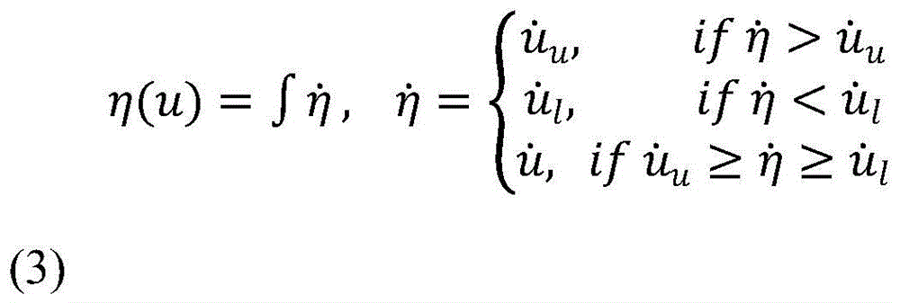
wherein etauAnd ηlSaturating the upper and lower limits for a known amplitude, and
and the upper and lower limits are saturated for a known rate.
Rewriting the system (1) into the form of a state equation:


v=sat(η(u))
(4)
wherein, θ=[-θ1,-θ2,...-θr,d1]T,φ=[φ1,φ2,...,φr,1]T,x1being the only measurable output of the nonlinear system, bcFor unknown gain, v is actuator output, u is controller output signal, d1Is a bounded, slowly time-varying perturbation;
the control objective is to design a control law using the available output x such that the output x of the system tracks a smooth reference trajectory x within a bounded error rangerAnd all other signals of the closed loop system are bounded.
It should be noted that the above equation of state (4) is a nonlinear system called Brunovsky type. Although the system covered by equation (4) appears to be limited compared to some other forms of nonlinear system, many strict feedback nonlinear systems can be converted to this standard form, and in practice many real physical systems can also be directly represented as models of this form.
Meanwhile, equation of state (4) contains uncertain control gain and control input rate constraints. The current prior art often adopts a neural network method to deal with the uncertainty. Although the neural network approach is not the focus of the discussion herein, it is also directly applicable to the approach herein. The approach herein is more practical and versatile since uncertain control gain and input rate constraints are common in practical applications.
In order to be able to effectively solve the above control problem, the system described by equation of state (4) is assumed as follows:
suppose 1. the state of equation of state (4) is only closedClosed compact set omegaXIn a variation of, i.e. [ x ]1,x2,...,xn]T∈ΩX∈RnAnd the system is controllable under control input constraints. The order n of the system is known.
Assumption 2. Direction or sign of high frequency control gain of Systemc) Are known.
Suppose 3. reference trajectory xrAnd its front p order derivative xr (ρ)(ρ ≦ n) is known and bounded.
For a system with control input constraints, it is reasonable to assume 1. In a sense, this can also be understood as the system being input-output stable, even though this feature is hard to see from equation of state (4) itself. Without this assumption, it is not practical to expect a control input to be able to control the system to a stable range when the state of the system has an arbitrarily large value and is outside the effectively controllable range for a system with constraints on the control input.
With the above problem explanation and assumption, the embodiment of the present application provides a nonlinear system output feedback adaptive control system using the HOSM observer, and the construction process and principle of this system are explained below.
Because only the output x is in the system (4)1Are measurable and therefore require the estimation of other states in the system by designing a suitable observer. The higher order sliding mode observer (HOSM observer) has some powerful characteristics that can be used for the estimation of the unmeasured states in (4).
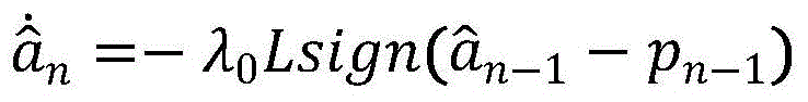
For a time-varying signal a (t) defined at [0, ∞ ], it consists of a bounded, unknown but Lebesgue-detectable interference signal and an unknown base signal a0(t) composition. a is a0The n-th derivative of (t) has a defined Lipschitz constant L0Is greater than 0. The HOSM observer of the following form can estimate the time derivatives of the various orders of a (t).


Wherein, the 0 th time derivative of the time varying signal a (t),
 is the 1 st time derivative of the time varying signal a (t),
 is the n-1 order time derivative of the time varying signal a (t),
 is the nth order time derivative of the time-varying signal a (t), a (t) e [0, ∞), L > 0 is a design constant, λiIs usually chosen to be λ0=1.1,λ1=1.5,λ2=3,λ3=5,λ4=8,λ512. The main characteristics of the state observer (5) are as in lemma 1:
1) in the absence of input noise, the parameters L and λ in equation (5) are appropriately selectediAnd a is a(n)(T) if a Lipschitz constant exists, then there exists a time T, for any T > T,

in this characteristic, the design constant L in the formula (5) must be sufficiently large as to be larger than the Lipschitz constant L0。
2) If the input noise satisfies the inequality | a (t) -a0(t) | < ε, then after a certain time, there is a normal number μi、vi(depending only on the parameters of equation (5)), the following inequality holds:


the HOSM observer in equation (5) can overcome some of the deficiencies of the standard sliding mode, such as signal buffeting and relative degree of freedom constraints. Property 1 shows that after a bounded time, a (t) and a can be obtained(i)(t) accurate estimation And
And this means that at any time T > T, the observation error is
 Or < deltai(δ is a small positive constant). This characteristic is generally satisfied
 Or < deltaiThe high gain observer of (2) has advantages.
The state observer using the HOSM observer can be designed independently of the system being estimated, only requiring the output of the system. Because of this feature, the controller and observer can be designed separately and the controller can be made to operateThe design is much easier as all states of the system can be measured. As described in and under assumption 1, the implementation of equation (5) requires an input signal a (t), i.e., x in system (4)iIs bounded, thereby ensuring the convergence of the observer. In practice, most physical systems operate in a limited interval and the rate of change of the signal is limited, so this constraint can be easily met.
Replacing a (t) in (5) with the system output x in (4)1Then (5) is a bounded observer of (4) with a bounded convergence time.
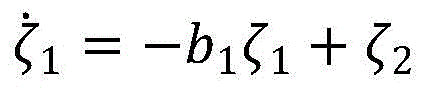
Before the control law is designed, in order to take into account the influence of the actuator saturation limit, a dynamic system is first constructed to generate a dynamic signal ζ [ ζ ] associated with the actuator saturation error1,ζ2,...,ζn]T。


Wherein b isi1,2, n is an adjustable normal number, is b in (4)cIt is updated by the following adaptation law (15). Δ u is v-u, v is the output of the actuator, u is the output signal of the controller, and ζ is a dynamic signal having a correlation with the actuator saturation error.
V is an output of the actuator, and may be an actual output of the controller. It is assumed here that v is available. If it is not measurable or accurate in a real system, the value of v can be obtained by numerical calculation using known upper and lower amplitude and rate saturation limits, as defined by (2) and (3).
In (8), an unknown gain b is includedcIs estimated by Δ u contains actuator errors due to actuator velocity saturation or other constraints. As such, this can be employed to improve the problem of inaccurate adaptive adjustment.
Further, the tracking error vector after being augmented by ζ is defined as:

wherein, in the step (9), the first step is carried out,
 being a conventional tracking error vector, - ζ is the extended dynamic error term caused by actuator saturation Δ u. When there is no actuator saturation, i.e., Δ u is 0, ζ → 0, 0]TEquation (9) is the conventional tracking error vector.
Due to the fact that In, only x1Are measurable and therefore in the following design, use is made of
 To replace
 Replacing a (t) in (5) with x1Then, then
 Can be obtained by the formula (5). According to (9), defining:

according to the main characteristics of the state observer (5), if the initial observation error is satisfied Or < deltai0Then, then
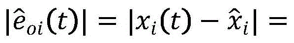 0 or < deltaiT > T means
 This means that
 (δ is a small normal number) and thus has
 t > 0. Since e includes an immeasurable amount, it is not available in the feedback control, and thus
 Will be used in the control law such that
 Or < deltac(δcA small positive constant). If in this case the actuator is not saturated, i.e. Δ u is 0, this is obtained
 Or < deltacThen the control target isThis can be achieved.
This is a method to solve the actuator constraint, and it also describes how to design the controller and observer separately using the features of the HOSM observer. Thus, estimation of the tracking error vector e Will be used in the following design process.
Defining scalar tracking errors es and is the error vector e and
 linear combination of medium elements:

wherein pi ═ pi1,π2,...,πn-1]TIs chosen as a constant vector such that the polynomial sn-1+πn-1sn-2+...+π1Is Hurwitz stable. Thus, it is clear that if es→0, Then e | | → 0,
defining observation errors And
And comprises the following steps:

and define

Wherein i 1. Due to phiiTo satisfy a smooth non-linear function of a consistent Lipschitz condition, and then
then t>0(δφA bounded normal number).
From the above relationship, the error e can be derivedsThe dynamic equation of (a) is:

wherein, is the unknown gain bcEstimate of (c), B ═ diag ([ B ])1,b2,…,bn]) Is a diagonal matrix, biIs defined in (8).
According to the error esThe adaptive control law of the system is designed as follows:

wherein k is1> 0 is an optional normal number, for a vector of unknown parameters thetaTIs estimated.
 For estimation of the tracking error vector e, the tracking error vector
 Wherein,
 as a conventional tracking error vector, - ζ is an extended dynamic error term caused by actuator saturation Δ u, Δ u being v-u, v being the output of the actuator, u being the output signal of the controller, B being diag ([ B)1,b2,…,bn]) Is a diagonal matrix, biN is an adjustable normal number, phi, 1,21,φ2,...,φr,1]T。


wherein, Γ ═ ΓT> 0 is a symmetric positive definite gain matrix, gammabA gain of a normal number > 0, σ1,σ2Is greater than 0. (15) In (1) And
And is the e-modification of the adaptive law and is used for enhancing the robustness of the adaptive law.
The following is a stability analysis of the adaptive control system described above.
2, leading: taking into account dynamic systems c, d > 0, μ (t) is a bounded smooth function, and | μ (t) | ≦ εηThen ψ (T) is also bounded and for some finite time TψLater, the method has | psi (T) | < d/c, T > Tψ。
Thus, according to lemma 2, in the adaptive law (16) And
And is bounded.
By substituting (14) the control law (15), the closed-loop dynamics of the error es can be obtained as follows:

wherein, in the above second step, equations (12) and (13) are employed.
As known to those skilled in the art, theorem 1: considering the system described by equation (4), using equation (5) as the observer, then using the adaptive control laws of (15) and (16) can be such that:
1) all signals in a closed loop system are consistently bounded;
2) the system output x can track a smooth reference track x within a limited error ranger。
The following was demonstrated:
consider the following Lyapunov candidate function:

deriving from (17) to obtain:

applying the adaptation law (16) and noting that Equation (18) can be converted to:

it is noted that And applying the Young's inequality to obtain:


according to the above guiding explanation (the system output x can track a smooth reference track x within a limited error ranger) And an Thus, it is possible to provide
 And
And is bounded.Since v is amplitude constrained and the system is input-output stable, phiiIs a smooth non-linear function with consistent Lipschitz conditions, then
 I phi i and
 is also bounded. Equation (19) can be rewritten as:

wherein, tau0Can be increased by increasing k1To reduce the error of the second term with the observer
 The value of this term is correlated and can be reduced by selecting appropriate observer parameters.
Therefore, according to the formula (20), when When the temperature of the water is higher than the set temperature,
 this proves the tracking error esIs consistently bounded, so that the output x of the system can track a smooth reference trajectory x with limited errorrAnd is and
 and
and is also bounded. According to hypothesis 1, system state xiAnd is also bounded, then ζ in equation (8) and u in equation (15) are also bounded.
The certification is over.
It should be noted that, if the adaptive control law (16) is designed as follows:


i.e., sigma-modification to enhance the robustness of the adaptive law, it can be shown that the transient state of the tracking error es and the final error magnitude can be adjusted by adjusting the parameters of the control law and the adaptive law.
In addition, if the observer (5) is operating in an ideal state, i.e. with a view to a large number of observer positions
 And using a standard conventional adaptation law,


the derivative of the previous Lyapunov function V can be shown to be The second derivative is
 Are consistently bounded. Therefore, the temperature of the molten metal is controlled,
 are consistently continuous. At the same timeIt can be seen that V, as a function of time, approaches a limit when t → ∞. According to the Barbalt theorem, there is
 This means that
 When the saturation limit of the actuator disappears at this time, this means that
The implementation principle of the nonlinear system output feedback adaptive control system adopting the HOSM observer is explained in detail below by using the adaptive control system to control the dynamic principle of the delta wing aircraft under the condition of a large attack angle.
Referring to fig. 1, fig. 1 is a schematic structural diagram of a delta wing aircraft according to an embodiment of the present application.
When the delta wing aircraft flies at a large angle of attack, the open loop roll dynamics of the delta wing aircraft is unstable at the origin balance point, and a limit loop (wing rolling problem) exists. This local roll angle oscillation is caused by asymmetrical unsteady aerodynamic effects acting on the delta wing. Thus, the roll dynamics of delta wing aircraft require active control.
The roll dynamics of a delta wing aircraft can be adjusted by means of bilaterally symmetrical movable surfaces (ailerons) located at the rear of the aircraft wings. The left aileron moves down (positive deflection) and the right aileron moves up (negative deflection), causing the aircraft to roll in the forward direction, i.e., the right wing rotates downward. The difference in the deflection of the left and right ailerons, referred to as the "differential ailerons," is the primary control input for adjusting the roll angle of the aircraft.
The general delta wing roll dynamics model is as follows:


wherein Is the roll angle; p (rad/s) is the roll rate; v (delta)c) For the actual aileron differential yaw angle (rad), which is also the actual control input, v (·) is defined in (4); deltac(rad) is the aileron differential control signal generated by the control law. (23) The actual values of the unknown constants are:
θ1=-0.018,θ2=0.015,θ3=-0.062,θ4=0.009,θ5=0.021,θ6=0.75,θ7=0.01。
compared with the prior art, the formula (23) adds the amplitude and the rate saturation of the differential deflection of the aileron and the constant disturbance theta7。θ6Corresponding to the indeterminate control gain b in (4)c. Here, it is assumed that only the roll angle is present Is measurable.
Note that in equation (23), the unit of angle is radian (rad), and the unit of angular velocity is radian/second (rad/s). For convenience, in the following simulation result curves, the angle is in degrees and the angular velocity is in degrees/sec.
The control aims to ensure that the roll angle of the delta wing aircraft can follow the proper roll angle command through active control under the condition that the input limit of the actuator exists
Based on the dynamic model of the delta wing aircraft, the principle that the nonlinear system output feedback adaptive control system adopting the HOSM observer controls the flight of the delta wing aircraft is explained in detail as follows:
amplitude sum of differential aileron deflection in equation (23)Rate saturation parameter set to ηu20 degrees, ηlThe temperature of the steel is-20 degrees, it should be noted that these values are only an optional embodiment, and can be set according to requirements in practical use.
Roll angle command Reference tracking trajectory for generating roll angle through filtering by following second-order transfer function

Wherein ω isn1, xi 0.95, for defining a smooth reference tracking function And derivatives thereof
 These values are used in the control law. Roll angle
 By following a reference tracking function
 To trace instructions
Replacing a (t) in (5) with the roll angle in formula (23) (23) The estimation of the state p in (b) can be provided by the HOSM observer. Then can obtain
 θ=[θ1,θ2,θ3,θ4,θ5,θ7]T,bc=θ6。
To reduce the disturbance in the estimated states, the order of the HOSM observer is taken to be 4 (i.e., in equation (5), n is 3), which is higher than the order of the system (23), but only the first two states are used for state estimation of (23). (5) The HOSM observer parameter in (1) is selected as L1000, lambda3=5,λ2=3,λ1=1.5,λ01.1, the observer has an initial value of

The adaptive control laws are designed according to (15) and (16). Wherein the design parameter is k1=1,ΠT=[4]T,B=diag([b1,b2]),b1=0.9,b2=0.9,Γ=diag([10,100,1000,100,40,10]),σ1=0.01,γb=400,σ2=0.01。
(16) Adaptive parameter of And
And has an initial value of
 These parametersThe values of (a) indicate that prior to roll angle closed-loop control, there is little known parameter information, excluding the assumed control efficiency
 Outside the initial value.
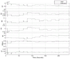
Roll angle command for a series of step changes The simulation results of the roll angle closed-loop control are shown in fig. 2.
It can be seen that the roll angle is at the beginning of the closed loop control even in the presence of uncertainty and actuator constraints in the system The reference track can be tracked within an appropriate range
 Thereby following the step instruction
 The estimated roll rate from the HOSM observer is substantially the same as the true roll rate. FIG. 2(c) shows that even though the control law signals are outside the range of actuator limits, the actual differential aileron deflection is well within the amplitude and velocity limits. The parameters estimated in FIG. 2(d) perform well throughout the control process, except for θ7And controlling the gain bcIn addition, most parameters do not converge to their true values.
The roll angle dynamic model in equation (23) has the same standard form as (4). To make the problem more challenging, embodiments of the present application can also be applied in a more complex kinetic model (25) where the states are paired Some imaginary direct input is added. The dynamical model (25) is still adaptively controlled using the adaptive control system designed as described above,without any changes, it is described in detail below:


referring to fig. 3, fig. 3(a) is a schematic diagram of a second roll angle output parameter and a second target parameter provided by the embodiment of the present application. Fig. 3(b) is a second schematic diagram of the control signal and the actual aileron deflection signal provided by the embodiment of the present application.
As can be seen by comparing FIG. 2 with FIG. 3, the roll angle in FIG. 3 The output response is almost the same as in fig. 2. Control signal deltacAnd the actual differential aileron deflection is somewhat different from that of figure 2. This is a natural consequence of the adaptive control system applying different dynamical models.
Therefore, it can be seen that the adaptive output feedback control method designed above has good robustness and adaptive capability to system changes.
In summary, the nonlinear system output feedback adaptive control system and method using the HOSM observer provided in the embodiments of the present application utilize the strong characteristics of the HOSM observer, and can accurately estimate the unmeasured state of the system only by the output of the observed system. This relatively independent observer design may make the controller design easier, as all states of the system can be measured. An auxiliary dynamic system driven by actuator saturation errors, with appropriate parameter selection, can effectively cope with the actuator constraints of the system. Stability analysis shows that the closed loop system is consistently bounded. The control results of the roll dynamics of the delta wing aircraft show that the proposed control method is effective and has good performance.
The above description is only for the specific embodiments of the present application, but the scope of the present application is not limited thereto, and any changes or substitutions that can be easily conceived by those skilled in the art within the technical scope of the present application should be covered within the scope of the present application. Therefore, the protection scope of the present application shall be subject to the protection scope of the claims.
Claims (4)
1. A nonlinear system output feedback self-adaptive control system adopting an HOSM observer is characterized by comprising a state observer adopting the HOSM, a dynamic system of an object to be controlled, a self-adaptive law and a control law;
a single input single output nonlinear system with input actuator limitations is proposed:

v=sat(η(u))
where x (t) is the measurable output, φiIs a known non-linear smoothing function that satisfies the consistent Lipschitz condition, θiAs an unknown constant, bcControlling gain for unknown constants, v being actuator output, d1For bounded slow time-varying disturbances, u is the controller output signal; sat (-) and η (-) are the amplitude saturation function and the rate saturation function of the actuator, respectively, and are defined as:


wherein eta isuAnd ηlSaturating the upper and lower limits for a known amplitude, and
and saturating the upper and lower limits for a known rate;
rewriting the nonlinear system with single input and single output limited by input actuators into the form of the following equation of state:


v=sat(η(u))
wherein x is x1, …,
…, θ=[-θ1,-θ2,…-θr,d1]T,φ=[φ1,φ2,…,φr,1]T,x1Being the only measurable output of the nonlinear system, bcFor unknown gain, v is the output of the actuator, u is the output signal of the controller, d1Is a bounded, slowly time-varying perturbation;
the state observer includes:


wherein, the 0 th time derivative of the time varying signal a (t),
 is the 1 st time derivative of the time varying signal a (t),
 is the n-1 order time derivative of the time varying signal a (t),
 is the time derivative of order n-1, L, λ, of the time-varying signal a (t)1…λnHOSM observer parameters;
the control law includes:

wherein k is1>0 is a selectable normal number which is a constant number, for a vector of unknown parameters thetaTIs estimated by the estimation of (a) a,
 for estimation of the tracking error vector e, the tracking error vector
 Wherein,
 as a conventional tracking error vector, - ζ is an extended dynamic error term caused by actuator saturation Δ u, Δ u being v-u, v being the output of the actuator, u being the output signal of the controller, B being diag ([ B)1,b2,…,bn]) Is a diagonal matrix, biI is 1,2, …, n is an adjustable normal number, phi is [ phi ]1,φ2,…,φr,1]T;
Estimation of unknown parameter vectors And estimation of unknown gain
 The calculation is performed according to the following adaptation law:


wherein, Γ ═ ΓT>0 is a symmetric positive definite gain matrix, gammab>0 is the normal number gain, σ1,σ2>0, And
And is the e-modification of the adaptation law.
2. The nonlinear system output feedback adaptive control system employing a HOSM observer of claim 1, wherein for actuator saturation limits of the actuator, a dynamic system related to the actuator saturation limits is constructed that is driven by actuator saturation errors, the dynamic system generating a dynamic signal ζ for use in subsequent controller design, the dynamic system comprising:
ζ=[ζ1,ζ2,…,ζn]T


wherein b isiI is 1,2, …, n is an adjustable normal number, is an unknown gain bcIs updated by the adaptive law, Δ u is v-u, v is actuator' sAnd the output u is an output signal of the controller, and zeta is a dynamic signal which has a correlation relation with the saturation error of the actuator.
3. A nonlinear system output feedback self-adaptive control method adopting an HOSM observer is characterized by comprising the following steps:
s1, a single input single output nonlinear system with input actuator constraints is proposed:

v=sat(η(u))
where x (t) is the measurable output, φiIs a known non-linear smoothing function that satisfies a consistent Lipschitz condition, θiAs an unknown constant, bcControl gain for unknown constants, v is actuator output, d1For bounded slow time-varying disturbances, u is the controller output signal; sat (-) and η (-) are the amplitude saturation function and the rate saturation function of the actuator, respectively, and are defined as:


wherein eta isuAnd ηlSaturating the upper and lower limits for a known amplitude, and
and saturating the upper and lower limits for a known rate;
s2: rewriting the nonlinear system with single input and single output limited by input actuators into the form of the following equation of state:


v=sat(η(u))
wherein x is x1, …,
…, θ=[-θ1,-θ2,…-θr,d1]T,φ=[φ1,φ2,…,φr,1]T,x1Being the only measurable output of the nonlinear system, bcFor unknown gain, v is the output of the actuator, u is the output signal of the controller, d1Is a bounded, slowly time-varying perturbation;
s3: constructing a state observer adopting HOSM, a dynamic system of an object to be controlled, an adaptive law and a control law, wherein the state observer comprises:


wherein, the 0 th time derivative of the time varying signal a (t),
 is the 1 st time derivative of the time varying signal a (t),
 is the n-1 order time derivative of the time varying signal a (t),
 is the n-1 time derivative, L, λ, of the time-varying signal a (t)1…λnHOSM observer parameters;
the control law includes:

wherein k is1>0 is a selectable normal number which is a constant number, for a vector of unknown parameters thetaTIs estimated by the estimation of (a) a,
 for estimation of the tracking error vector e, the tracking error vector
 Wherein,
 as a conventional tracking error vector, - ζ is an extended dynamic error term caused by actuator saturation Δ u, Δ u being v-u, v being the output of the actuator, u being the output signal of the controller, B being diag ([ B)1,b2,…,bn]) Is a diagonal matrix, biWhere i is 1,2, …, n is an adjustable constant, phi is [ phi ]1,φ2,…,φr,1]T;
Estimation of unknown parameter vectors And estimation of unknown gain
 The calculation is performed according to the following adaptive law:

wherein, Γ ═ ΓT>0 is a symmetric positive definite gain matrix, gammab>0 is the normal number gain, σ1,σ2>0, And
And is the e-modification of the adaptation law.
4. The nonlinear system output feedback adaptive control method using the HOSM observer of claim 3, wherein for actuator saturation limits of the actuators, a dynamic system related to the actuator saturation limits is constructed that is driven by actuator saturation errors, the dynamic system generating dynamic signals for use in subsequent controller design, the dynamic system comprising:
ζ=[ζ1,ζ2,…,ζn]T


wherein b isiI is 1,2, …, n is an adjustable normal number, is an unknown gain bcIs updated by the adaptive law, Δ u is v-u, v is the output of the actuator, u is the output signal of the controller, and ζ is a dynamic signal having a correlation with the actuator saturation error.
Priority Applications (1)
| Application Number | Priority Date | Filing Date | Title |
|---|---|---|---|
| CN202110392290.9A CN113110048B (en) | 2021-04-13 | 2021-04-13 | Nonlinear system output feedback adaptive control system and method adopting HOSM observer |
Applications Claiming Priority (1)
| Application Number | Priority Date | Filing Date | Title |
|---|---|---|---|
| CN202110392290.9A CN113110048B (en) | 2021-04-13 | 2021-04-13 | Nonlinear system output feedback adaptive control system and method adopting HOSM observer |
Publications (2)
| Publication Number | Publication Date |
|---|---|
| CN113110048A CN113110048A (en) | 2021-07-13 |
| CN113110048B true CN113110048B (en) | 2022-06-17 |
Family
ID=76716075
Family Applications (1)
| Application Number | Title | Priority Date | Filing Date |
|---|---|---|---|
| CN202110392290.9A Active CN113110048B (en) | 2021-04-13 | 2021-04-13 | Nonlinear system output feedback adaptive control system and method adopting HOSM observer |
Country Status (1)
| Country | Link |
|---|---|
| CN (1) | CN113110048B (en) |
Families Citing this family (4)
| Publication number | Priority date | Publication date | Assignee | Title |
|---|---|---|---|---|
| CN113885314B (en) * | 2021-10-22 | 2023-05-23 | 电子科技大学 | Nonlinear system tracking control method with unknown gain and interference |
| CN114063458B (en) * | 2021-11-19 | 2022-05-20 | 中国矿业大学 | A Preset Performance Control Method for Non-triangular Structure Systems Independent of Initial Conditions |
| CN114839882B (en) * | 2022-06-24 | 2024-09-17 | 中国空气动力研究与发展中心设备设计与测试技术研究所 | Nonlinear system composite self-adaptive control method under input constraint |
| CN116430737B (en) * | 2023-06-13 | 2023-08-18 | 中国空气动力研究与发展中心设备设计与测试技术研究所 | Self-adaptive control method of input delay nonlinear system |
Citations (1)
| Publication number | Priority date | Publication date | Assignee | Title |
|---|---|---|---|---|
| CN108303885A (en) * | 2018-01-31 | 2018-07-20 | 南京理工大学 | A kind of motor position servo system self-adaptation control method based on interference observer |
Family Cites Families (6)
| Publication number | Priority date | Publication date | Assignee | Title |
|---|---|---|---|---|
| US8436283B1 (en) * | 2008-07-11 | 2013-05-07 | Davidson Technologies Inc. | System and method for guiding and controlling a missile using high order sliding mode control |
| US20170207415A1 (en) * | 2014-09-10 | 2017-07-20 | Konica Minolta, Inc. | Gas barrier film and organic electroluminescent element |
| CN105022271A (en) * | 2015-06-09 | 2015-11-04 | 西北工业大学 | An unmanned aerial vehicle self-adaptive PID control method |
| MX2020006508A (en) * | 2017-12-18 | 2020-09-17 | Regeneron Pharma | Bispecific antigen binding molecules that bind leptin receptor and/or gp130, and methods of use thereof. |
| CN111506095B (en) * | 2020-04-24 | 2021-04-06 | 北京科技大学 | A saturated fixed-time relative pose tracking control method between feature points of two rigid bodies |
| CN112394639B (en) * | 2020-11-20 | 2021-08-24 | 西安热工研究院有限公司 | Nuclear power unit control rod adjusting method and system with incremental adjusting function |
-
2021
- 2021-04-13 CN CN202110392290.9A patent/CN113110048B/en active Active
Patent Citations (1)
| Publication number | Priority date | Publication date | Assignee | Title |
|---|---|---|---|---|
| CN108303885A (en) * | 2018-01-31 | 2018-07-20 | 南京理工大学 | A kind of motor position servo system self-adaptation control method based on interference observer |
Also Published As
| Publication number | Publication date |
|---|---|
| CN113110048A (en) | 2021-07-13 |
Similar Documents
| Publication | Publication Date | Title |
|---|---|---|
| CN113110048B (en) | Nonlinear system output feedback adaptive control system and method adopting HOSM observer | |
| Djordjevic et al. | Data-driven control of hydraulic servo actuator: An event-triggered adaptive dynamic programming approach | |
| Djordjevic et al. | Data-driven control of hydraulic servo actuator based on adaptive dynamic programming. | |
| Deng et al. | Time‐varying input delay compensation for nonlinear systems with additive disturbance: An output feedback approach | |
| Xu et al. | Global neural dynamic surface tracking control of strict-feedback systems with application to hypersonic flight vehicle | |
| Chen et al. | Adaptive neural output feedback control of uncertain nonlinear systems with unknown hysteresis using disturbance observer | |
| Xu et al. | Composite fuzzy control of a class of uncertain nonlinear systems with disturbance observer | |
| CN110673472B (en) | Adaptive Robust Control Method Based on Neural Network Compensation for Dead Zone Inversion Error | |
| CN106094530B (en) | The Design of non-linear controllers method of inverted pendulum | |
| CN103616818A (en) | Self-adaptive fuzzy neural global rapid terminal sliding-mode control method for micro gyroscope | |
| CN108363293B (en) | Cross coupling control algorithm and system based on PID control | |
| Shi et al. | Robust model reference adaptive control based on linear matrix inequality | |
| CN106774273A (en) | For the algorithm based on sliding mode prediction fault tolerant control method of time_varying delay control system actuator failures | |
| CN104614984A (en) | High-precision control method of motor position servo system | |
| Pan et al. | Online data‐driven composite adaptive backstepping control with exact differentiators | |
| Ghafarirad et al. | Observer-based sliding mode control with adaptive perturbation estimation for micropositioning actuators | |
| CN110286595A (en) | A Class of Adaptive Control Method for Fractional Order Systems Affected by Saturated Nonlinear Inputs | |
| CN115220467A (en) | An Attitude Control Method for Flying Wing Aircraft Based on Neural Network Incremental Dynamic Inverse | |
| CN114637318A (en) | Sliding mode control method for hypersonic aircraft | |
| Lee et al. | Composite adaptive control and identification of MIMO aeroelastic system with enhanced parameter excitation | |
| CN108469734A (en) | Consider the motor servo system Auto-disturbance-rejection Control of state constraint | |
| CN114839882B (en) | Nonlinear system composite self-adaptive control method under input constraint | |
| Jeon et al. | Adaptive sliding mode control of ball and plate systems for its practical application | |
| CN110829933B (en) | Neural network output feedback self-adaptive robust control method based on transmitting platform | |
| CN111776250A (en) | Error compensation control method of spacecraft assembly based on interferometric neural network |
Legal Events
| Date | Code | Title | Description |
|---|---|---|---|
| PB01 | Publication | ||
| PB01 | Publication | ||
| SE01 | Entry into force of request for substantive examination | ||
| SE01 | Entry into force of request for substantive examination | ||
| GR01 | Patent grant | ||
| GR01 | Patent grant |