CN113098406A - System and method for compensating for narrow-band distortion in power semiconductor devices - Google Patents
System and method for compensating for narrow-band distortion in power semiconductor devices Download PDFInfo
- Publication number
- CN113098406A CN113098406A CN202011537629.1A CN202011537629A CN113098406A CN 113098406 A CN113098406 A CN 113098406A CN 202011537629 A CN202011537629 A CN 202011537629A CN 113098406 A CN113098406 A CN 113098406A
- Authority
- CN
- China
- Prior art keywords
- filter network
- power amplifier
- nonlinear
- output
- filters
- Prior art date
- Legal status (The legal status is an assumption and is not a legal conclusion. Google has not performed a legal analysis and makes no representation as to the accuracy of the status listed.)
- Granted
Links
- 239000004065 semiconductor Substances 0.000 title claims abstract description 40
- 238000000034 method Methods 0.000 title claims abstract description 20
- 238000012937 correction Methods 0.000 claims abstract description 41
- 230000000694 effects Effects 0.000 claims abstract description 32
- 230000004044 response Effects 0.000 claims abstract description 12
- 239000000872 buffer Substances 0.000 claims description 28
- JMASRVWKEDWRBT-UHFFFAOYSA-N Gallium nitride Chemical compound [Ga]#N JMASRVWKEDWRBT-UHFFFAOYSA-N 0.000 claims description 17
- 238000005070 sampling Methods 0.000 claims description 11
- 150000001875 compounds Chemical class 0.000 claims description 9
- 230000009467 reduction Effects 0.000 claims description 8
- 230000006870 function Effects 0.000 description 44
- 238000012549 training Methods 0.000 description 27
- 229910002601 GaN Inorganic materials 0.000 description 13
- 239000013598 vector Substances 0.000 description 12
- 230000008569 process Effects 0.000 description 11
- 239000011159 matrix material Substances 0.000 description 8
- 238000005516 engineering process Methods 0.000 description 7
- 238000012545 processing Methods 0.000 description 7
- 238000004422 calculation algorithm Methods 0.000 description 6
- 230000001934 delay Effects 0.000 description 6
- XUIMIQQOPSSXEZ-UHFFFAOYSA-N Silicon Chemical compound [Si] XUIMIQQOPSSXEZ-UHFFFAOYSA-N 0.000 description 4
- 230000003111 delayed effect Effects 0.000 description 4
- 238000004519 manufacturing process Methods 0.000 description 4
- 229910052710 silicon Inorganic materials 0.000 description 4
- 239000010703 silicon Substances 0.000 description 4
- 238000004891 communication Methods 0.000 description 3
- 230000006872 improvement Effects 0.000 description 3
- 230000001052 transient effect Effects 0.000 description 3
- 238000013459 approach Methods 0.000 description 2
- 238000007599 discharging Methods 0.000 description 2
- 229910044991 metal oxide Inorganic materials 0.000 description 2
- 150000004706 metal oxides Chemical class 0.000 description 2
- 238000005406 washing Methods 0.000 description 2
- JBRZTFJDHDCESZ-UHFFFAOYSA-N AsGa Chemical compound [As]#[Ga] JBRZTFJDHDCESZ-UHFFFAOYSA-N 0.000 description 1
- GPXJNWSHGFTCBW-UHFFFAOYSA-N Indium phosphide Chemical compound [In]#P GPXJNWSHGFTCBW-UHFFFAOYSA-N 0.000 description 1
- 230000006978 adaptation Effects 0.000 description 1
- 230000032683 aging Effects 0.000 description 1
- 230000006399 behavior Effects 0.000 description 1
- 230000005540 biological transmission Effects 0.000 description 1
- 238000004364 calculation method Methods 0.000 description 1
- 230000010267 cellular communication Effects 0.000 description 1
- 230000001413 cellular effect Effects 0.000 description 1
- 238000012512 characterization method Methods 0.000 description 1
- 238000001816 cooling Methods 0.000 description 1
- 230000007812 deficiency Effects 0.000 description 1
- 239000006185 dispersion Substances 0.000 description 1
- 238000001035 drying Methods 0.000 description 1
- 238000010438 heat treatment Methods 0.000 description 1
- 230000008676 import Effects 0.000 description 1
- 239000012212 insulator Substances 0.000 description 1
- 238000012886 linear function Methods 0.000 description 1
- 230000007774 longterm Effects 0.000 description 1
- 239000000463 material Substances 0.000 description 1
- 238000012986 modification Methods 0.000 description 1
- 230000004048 modification Effects 0.000 description 1
- 230000002093 peripheral effect Effects 0.000 description 1
- 230000000644 propagated effect Effects 0.000 description 1
- HBMJWWWQQXIZIP-UHFFFAOYSA-N silicon carbide Chemical compound [Si+]#[C-] HBMJWWWQQXIZIP-UHFFFAOYSA-N 0.000 description 1
- 238000004088 simulation Methods 0.000 description 1
- 238000006467 substitution reaction Methods 0.000 description 1
- 238000012360 testing method Methods 0.000 description 1
- 230000007704 transition Effects 0.000 description 1
Images


Classifications
-
- H—ELECTRICITY
- H04—ELECTRIC COMMUNICATION TECHNIQUE
- H04B—TRANSMISSION
- H04B1/00—Details of transmission systems, not covered by a single one of groups H04B3/00 - H04B13/00; Details of transmission systems not characterised by the medium used for transmission
- H04B1/02—Transmitters
- H04B1/04—Circuits
- H04B1/0475—Circuits with means for limiting noise, interference or distortion
-
- H—ELECTRICITY
- H03—ELECTRONIC CIRCUITRY
- H03F—AMPLIFIERS
- H03F3/00—Amplifiers with only discharge tubes or only semiconductor devices as amplifying elements
- H03F3/189—High-frequency amplifiers, e.g. radio frequency amplifiers
- H03F3/19—High-frequency amplifiers, e.g. radio frequency amplifiers with semiconductor devices only
- H03F3/195—High-frequency amplifiers, e.g. radio frequency amplifiers with semiconductor devices only in integrated circuits
-
- H—ELECTRICITY
- H03—ELECTRONIC CIRCUITRY
- H03F—AMPLIFIERS
- H03F1/00—Details of amplifiers with only discharge tubes, only semiconductor devices or only unspecified devices as amplifying elements
- H03F1/32—Modifications of amplifiers to reduce non-linear distortion
- H03F1/3241—Modifications of amplifiers to reduce non-linear distortion using predistortion circuits
- H03F1/3247—Modifications of amplifiers to reduce non-linear distortion using predistortion circuits using feedback acting on predistortion circuits
-
- H—ELECTRICITY
- H03—ELECTRONIC CIRCUITRY
- H03F—AMPLIFIERS
- H03F1/00—Details of amplifiers with only discharge tubes, only semiconductor devices or only unspecified devices as amplifying elements
- H03F1/32—Modifications of amplifiers to reduce non-linear distortion
- H03F1/3241—Modifications of amplifiers to reduce non-linear distortion using predistortion circuits
- H03F1/3258—Modifications of amplifiers to reduce non-linear distortion using predistortion circuits based on polynomial terms
-
- H—ELECTRICITY
- H03—ELECTRONIC CIRCUITRY
- H03F—AMPLIFIERS
- H03F3/00—Amplifiers with only discharge tubes or only semiconductor devices as amplifying elements
- H03F3/20—Power amplifiers, e.g. Class B amplifiers, Class C amplifiers
- H03F3/21—Power amplifiers, e.g. Class B amplifiers, Class C amplifiers with semiconductor devices only
- H03F3/213—Power amplifiers, e.g. Class B amplifiers, Class C amplifiers with semiconductor devices only in integrated circuits
-
- H—ELECTRICITY
- H03—ELECTRONIC CIRCUITRY
- H03F—AMPLIFIERS
- H03F2200/00—Indexing scheme relating to amplifiers
- H03F2200/171—A filter circuit coupled to the output of an amplifier
-
- H—ELECTRICITY
- H03—ELECTRONIC CIRCUITRY
- H03F—AMPLIFIERS
- H03F2200/00—Indexing scheme relating to amplifiers
- H03F2200/451—Indexing scheme relating to amplifiers the amplifier being a radio frequency amplifier
-
- H—ELECTRICITY
- H03—ELECTRONIC CIRCUITRY
- H03F—AMPLIFIERS
- H03F2201/00—Indexing scheme relating to details of amplifiers with only discharge tubes, only semiconductor devices or only unspecified devices as amplifying elements covered by H03F1/00
- H03F2201/32—Indexing scheme relating to modifications of amplifiers to reduce non-linear distortion
- H03F2201/3224—Predistortion being done for compensating memory effects
-
- H—ELECTRICITY
- H04—ELECTRIC COMMUNICATION TECHNIQUE
- H04B—TRANSMISSION
- H04B1/00—Details of transmission systems, not covered by a single one of groups H04B3/00 - H04B13/00; Details of transmission systems not characterised by the medium used for transmission
- H04B1/02—Transmitters
- H04B1/04—Circuits
- H04B2001/0408—Circuits with power amplifiers
- H04B2001/0425—Circuits with power amplifiers with linearisation using predistortion
Landscapes
- Engineering & Computer Science (AREA)
- Power Engineering (AREA)
- Physics & Mathematics (AREA)
- Nonlinear Science (AREA)
- Microelectronics & Electronic Packaging (AREA)
- Signal Processing (AREA)
- Computer Networks & Wireless Communication (AREA)
- Algebra (AREA)
- General Physics & Mathematics (AREA)
- Mathematical Analysis (AREA)
- Mathematical Optimization (AREA)
- Pure & Applied Mathematics (AREA)
- Amplifiers (AREA)
Abstract
The present disclosure relates to systems and methods for compensating for narrowband distortion in power semiconductor devices. Some embodiments herein describe a radio frequency power semiconductor device for compensating low frequency noise of a power amplifier including a first nonlinear filter network. The first nonlinear filter network may include a plurality of infinite impulse response filters and corresponding correction elements to correct a nonlinear portion of the power amplifier. The radio frequency power semiconductor device may further include a second nonlinear filter network to compensate for the wideband distortion. The second nonlinear filter network may be connected in parallel with the first nonlinear filter network. The wide-band distortion may include digital predistortion and the narrow-band distortion may include charge trapping effects. The first nonlinear filter network may comprise a laguerre filter. The second nonlinear filter network may include a general purpose memory polynomial filter.
Description
Technical Field
The disclosed technology relates generally to semiconductor devices, and more particularly to power semiconductor devices in which narrow-band distortion effects are compensated.
Background
Radio transceivers may be used in a variety of Radio Frequency (RF) communication systems. For example, a transceiver may be included in a base station or mobile device to transmit and receive signals associated with a wide variety of communication standards, including, for example, cellular and/or Wireless Local Area Network (WLAN) standards. Transceivers may also be used in radar systems, instrumentation, industrial electronics, military electronics, portable computers, digital radios, and/or other electronic devices.
The RF communication system may further include a power amplifier for amplifying the RF transmit signal from the transceiver to a power level suitable for wireless transmission. There are various types of power amplifiers, including those utilizing silicon (Si) -based devices, gallium arsenide (GaAs) -based devices, indium phosphide (InP) -based devices, silicon carbide (SiC) -based devices, and gallium nitride (GaN) devices. Various types of power amplifiers may provide different advantages in terms of cost, performance, and/or operating frequency. For example, while silicon-based power amplifiers generally provide lower manufacturing costs, certain silicon-based power amplifiers are inferior to their compound semiconductor counterparts in terms of certain performance metrics.
Disclosure of Invention
Some embodiments include a Radio Frequency (RF) power semiconductor device, wherein the device comprises: a first non-linear filter network configured to compensate for narrowband distortion of a power amplifier, wherein the first non-linear filter network comprises a correction element configured to correct for a non-linear portion of the power amplifier; and a second nonlinear filter network configured to compensate for wideband distortion of the power amplifier.
In some implementations, the first nonlinear filter network includes a first plurality of Infinite Impulse Response (IIR) filters arranged in series.
In some implementations, a first filter of the first plurality of IIR filters includes a Low Pass Filter (LPF).
In some implementations, the second filter of the first plurality of IIR filters includes an all-pass filter.
In some implementations, the first plurality of IIR filters are orthogonal to each other.
In some embodiments, the first nonlinear filter network comprises a plurality of IIR filters 1 through N arranged in series, wherein the plurality of IIR filters 1 through N are arranged in parallel.
In some embodiments, the device further comprises 1 to N correction elements corresponding to the plurality of IIR filters 1 to N, wherein the 1 to N correction elements correct for the non-linear portion of the power amplifier before the correction signal propagates through the corresponding plurality of IIR filters.
In some embodiments, the correction of the non-linear portion of the power amplifier comprises applying an exponential to the amplitude of the signal for each of the 1 to N correction elements.
In some embodiments, the device further comprises: a power amplifier, wherein the power amplifier comprises a compound semiconductor power amplifier; and the narrow-band distortion is caused by a charge trapping effect when the compound semiconductor power amplifier is charged from low power to high power.
In some embodiments, the compound semiconductor power amplifier comprises a gallium nitride (GaN) power amplifier.
In some embodiments, the device further comprises: a down-sampler for down-sampling an input signal and transmitting the down-sampled signal to the first nonlinear filter network; and an upsampler to upsample an output of the first nonlinear filter network.
In some embodiments, the device further comprises: a mixer that mixes an output of the first nonlinear filter network with an input of the first nonlinear filter network; and a first buffer configured to delay an input of the first nonlinear filter network to match a timing of the signal with an output of the first nonlinear filter network.
In some embodiments, the device further comprises: a second buffer configured to delay an output of the mixer from the output to match the timing with an output of the FIR filter.
In some embodiments, the second nonlinear filter network comprises a plurality of Finite Infinite Response (FIR) filters.
In some implementations, the first nonlinear filter network includes a laguerre filter.
Some embodiments include a Radio Frequency (RF) power semiconductor device, wherein the device comprises: a first non-linear filter network configured to compensate for narrow-band distortion of a power amplifier, wherein the first non-linear filter network comprises a plurality of Infinite Impulse Response (IIR) filters and corresponding correction elements for correcting a non-linear portion of the power amplifier.
In some implementations, the plurality of IIR filters includes a laguerre filter.
In some embodiments, the device further comprises: a crest factor reduction function; and a second non-linear filter network configured to compensate for wideband distortion of the power amplifier, wherein the crest factor reduction function is in series with the second non-linear filter network.
In some embodiments, the second nonlinear filter network comprises a plurality of Finite Infinite Response (FIR) filters.
Some embodiments include a Digital Predistortion (DPD) method comprising: amplifying the transmit signal using a power amplifier; compensating for narrow-band distortion of the power amplifier by pre-distorting the transmit signal using a first non-linear filter network, including correcting a non-linear portion of the power amplifier using a correction element of a first non-linear filter; and compensating for wideband distortion of the power amplifier by pre-distorting the transmit signal using a second non-linear filter network.
Drawings
Fig. 1A depicts one example of a plot of Low Frequency (LF) gain over time, input amplitude modulation over time, and Error Vector Magnitude (EVM) over time without charge trapping Digital Predistortion (DPD).
FIG. 1B depicts an expanded portion of the graph of FIG. 1A.
FIG. 1C depicts one example of a plot of charge trapping gain versus time, charge trapping correction versus time, input amplitude modulation (in dB) versus time, and input amplitude modulation (in volts) versus time for a charge trapping DPD according to one embodiment.
Fig. 2A illustrates an RF semiconductor device including a first nonlinear filter network for correcting narrowband distortion and a second nonlinear filter network for correcting wideband distortion, in accordance with some embodiments.
Fig. 2B illustrates an example architecture of a first nonlinear filter network in accordance with some embodiments.
Fig. 3 illustrates an example architecture of a first nonlinear filter network including decimation and upsampling functions in accordance with some embodiments.
Fig. 4 illustrates an example architecture of a first nonlinear filter network including a crest factor reduction function and a delay matching function, according to some embodiments.
Fig. 5 illustrates an example architecture of an RF semiconductor device for training first and second nonlinear filter networks through a direct learning algorithm, in accordance with some embodiments.
Fig. 6 illustrates an example architecture for training a generalized storage polynomial (GMP) actuator, in accordance with some embodiments.
Fig. 7 illustrates an example architecture for training a laguerre actuator, according to some embodiments.
Fig. 8 illustrates an example architecture for identifying initial conditions for laguerre actuator training, in accordance with some embodiments.
Fig. 9 illustrates an example architecture for an RF semiconductor device to train both GMP and laguerre actuators simultaneously, in accordance with some embodiments.
Fig. 10 illustrates an RF semiconductor device according to some embodiments, including: a first nonlinear filter network comprising a FIR filter for correcting narrow band distortion; and a second nonlinear filter network for a FIR filter correcting the wide-band distortion.
Detailed Description
Charge trap and digital predistortion
Power devices, such as Radio Frequency (RF) power devices, are used in many applications, such as wireless technology. For various applications, power devices are based on silicon technology, such as Si-based Laterally Diffused Metal Oxide Semiconductor (LDMOS) devices. For certain applications, compound semiconductors (e.g., III-V materials) have advantages in high frequency operation. For example, gallium nitride (GaN) based power devices, such as DC/LF and RF power devices, have been proposed. In some applications, for example in process architectures where drain modulation is applied, it has been predicted that compound semiconductor power devices such as GaN-based power devices will have advantages over Si-based technologies. Expected advantages include improvements in efficiency and frequency range (e.g., higher unity gain cutoff frequency or f)T) And other advantages.
GaN has been widely used in a variety of applications, including Light Emitting Diode (LED) devices. Although interest in GaN RF power devices for various other commercial applications has been steadily increasing, the implementation of GaN-based power devices, including RF power devices, has been largely limited to small-scale applications such as military/aerospace. Part of the reason for the limited implementation is the manufacturing cost, which is currently significantly higher than Si-based technologies. There are currently two main types of GaN RF power devices, including GaN-on-insulator technology and GaN-on-Si technology. Although the former has higher performance, the wafer manufacturing cost is also higher.
In addition to cost considerations, certain technological improvements are sought in GaN-based power devices. One such improvement is related to addressing the relatively narrow-band distortion effects observed in GaN-based power devices. Without being bound to any particular theory, it is believed that charge trapping effects cause significant changes in device characteristics, including changes in gain linearity of GaN-based power devices. Charge trapping is considered a function of the long-term history of the input signal, which can last from milliseconds to seconds. The term used to denote this effect is "current collapse," which is used to describe an effect under which the drain current collapses to a level less than would be expected when a high power RF pulse is applied to a GaN transistor.
The effects of charge trapping include, but are not limited to, transconductance frequency dispersion, current collapse of the dc current consumption characteristics, gate lag transients, drain lag transients, and/or limited microwave power output.
Thus, when the power is modulated, charge can be trapped and then released at low frequencies, which results in low frequency modulation of the gain, which causes distortion. Accordingly, there is a need to mitigate or compensate for charge trapping effects in GaN-based power devices, as well as other types of power devices.
Fig. 1A, 1B, and 1C include graphs 102, 104, 106, 110, 112, and 114, 116, and 118 illustrating low frequency modulation of gain according to some embodiments. Graph 102 shows Error Vector Magnitude (EVM) over time. Graph 104 shows the input Amplitude Modulation (AM) signal in dB as a function of time. The input amplitude modulated signal is applied to a GaN amplifier, which produces a low frequency gain modulation. Graph 106 shows Low Frequency (LF) gain in dB as a function of time, with gain measured over a BW of 0Hz to 10 kHz. Graphs 110, 112, and 114 of FIG. 1B are close-up sections 108 of graphs 102, 104, and 106, respectively, of FIG. 1A.
As shown in graph 104, a pulse is generated in the input amplitude modulated signal. Graph 112 shows a low signal, e.g., between 6.5-7 milliseconds, and a high signal, e.g., between 7.1-7.2 milliseconds. However, when the signal is in both the high and low signal states, the signal is pulsating. Graph 106 shows the corresponding low frequency gain of the input amplitude modulated signal of graph 112. As shown, the low frequency gain shows the effect of the modulation.
The power amplifier is a non-linear device whose gain can be expanded and compressed depending on the current and past input amplitude. In Laterally Diffused Metal Oxide Semiconductor (LDMOS) devices, this gain modulation may comprise past amplitude values ranging from about 10ns to 100ns, while the non-linear memory of GaN devices may extend back by us, ms or even a few seconds. In some embodiments, the sampling frequency may be between 10-500 MHz. In some embodiments, the actuators of these systems may be trained in a time range of 1 nanosecond to 100 nanoseconds, 8 nanoseconds to 800 nanoseconds, 16 nanoseconds to 1600 nanoseconds, 32 nanoseconds to 3200 nanoseconds, 64 nanoseconds to 6400 nanoseconds, or the like.
A problem with the approach applied to low frequency charge trapping is that when these typical systems determine a correction for Digital Predistortion (DPD), the system may use a solver, such as a least squares solver. These least squares solvers use linear algebra in finite input impulse (FIR) filters. The FIR filter can use truncated Volterra series up to a general memory polynomial.
For charge trapping effects at low frequencies, the time constant can be 100 or 1,000 times longer. For example, if the charge trapping effect extends over 10 milliseconds in time at the power amplifier, these typical systems will have to store at least over 10 milliseconds of data. The vector and matrix for high frequency DPD distortion may require 300 to 400 columns. However, for low frequency charge trapping effects, the FIR filter computation will now have thousands of entries. A typical FIR filter uses a moving average of the weighted inputs and increases the number of taps in the FIR filter, which makes the process very complex.
Such calculations may result in numerical instability in the simulation, delays in latency to the antenna elements, and increases in circuit footprint and power consumption. Furthermore, linear algebra can be used to train and adapt DPD, and large systems of equations will be expensive and numerically unstable. Furthermore, if we use FIR to construct the DPD actuator and expand back to 100,000 samples in memory, the DPD actuator would be very expensive and require a large amount of power.
To be able to correct for charge trapping effects using a typical system, the FIR filter must filter out the time limit of thousands of samples. This would involve a significant amount of hardware to store each iteration of the FIR filter and a significant amount of power consumption. These typical systems are not suitable for transceiver and antenna processing chips where processing power and circuit footprint are limited. Moreover, the computer may not even have the ability to prove this concept in a simulator. The computations required for FIR filters become too complex and bulky from a numerical computation point of view.
Furthermore, another drawback of this approach is the use of non-linear terms at the input of the FIR filter to model the non-linear behavior of DPD. These typical systems may now have thousands of taps, where the system may send the absolute value of the signal to a first tap, the square of the absolute value of the signal to a second tap, the third square of the absolute value of the signal to a third tap, and so on, again resulting in the drawbacks described herein, such as increased circuit footprint and power consumption.
Nonlinear filter network capable of correcting narrowband and wideband frequency distortion
Systems and methods are described herein that address or mitigate the problem of charge trapping effects. Some embodiments include a Radio Frequency (RF) power semiconductor device configured to correct for charge trapping effects. In some embodiments, the RF semiconductor device can correct for charge trapping effects and broadband distortion of the power amplifier.
Fig. 2A illustrates an RF semiconductor device 200 including a first nonlinear filter network for correcting narrowband distortion and a second nonlinear filter network for correcting wideband distortion, in accordance with some embodiments. The device may include an actuator 202, a power amplifier 204 (including a FET, such as a GaN FET, in this example), a least squares module 206, and a feedback actuator 208.
As shown in fig. 2A, the actuator 202 may include a first nonlinear filter network 210 configured to compensate for narrow-band distortion of the power amplifier, such as frequencies from 10kHz to 0.1 Hz. The first nonlinear filter network 210 may include a plurality of nonlinear filters, such as Infinite Impulse Response (IIR) filters. In this embodiment, the IIR filter may be used collectively as a laguerre filter. The first nonlinear filter network 210 may include cascaded or IIR filter chains. In some embodiments, the first filter is a low pass filter and subsequent filters in the IIR filter chain are all pass filters. In some embodiments, the filters of the first nonlinear filter network 210 are orthogonal to each other. The use of IIR filters allows the system to use long time constants to account for narrow band charge trapping effects. The use of laguerre filters for correcting narrow band charge trapping effects is not known.
In some embodiments, the second nonlinear filter network 212 may be configured to compensate for wideband distortion of the power amplifier. The second nonlinear filter network 212 may include a plurality of nonlinear filters, such as Finite Impulse Response (FIR) filters. The FIR filters may collectively function as a Generalized Memory Polynomial (GMP) filter. In some embodiments, the second nonlinear filter network 212 may include a Digital Predistortion (DPD) system and/or a DPD filter network that compensates for wideband distortion.
In some implementations, the input signal x is fed to a first nonlinear filter network 210 to produce a signal to compensate for the narrow-band distortion. The same input signal may be fed into a second nonlinear filter network 212 to compensate for the wideband distortion. The combination of the outputs of the first nonlinear filter network 210 and the second nonlinear filter network 212 are summed by an adder 214. The output of the adder 214 is fed to the power amplifier 204. In some embodiments, the input signal x corresponds to a digital data stream (e.g., in-phase (I) and quadrature-phase (Q) data) provided by a baseband processor.
Although shown as being provided directly to power amplifier 204, the output of summer 214 may correspond to being processed by one or more, digital-to-analog converters (DACs), one or more mixers, one or more Variable Gain Amplifiers (VGAs), and/or other circuitry to generate an RF transmit signal that is provided to the input of power amplifier 204.
In some embodiments, the output and input of the power amplifier 204 are also used to fit an inverse model, such as the feedback actuator 208. The output of the power amplifier 204 may be fed into another first nonlinear filter network 218 and another second nonlinear filter network 216. In some embodiments, the input power and/or output power of the power amplifier 204 is captured by the directional coupler and then processed by the observation receiver to produce a digital representation of the observed power.
With continued reference to fig. 2A, the outputs of the further first nonlinear filter network 218 and the further second nonlinear filter network 216 are added by an adder 220. The input of the power amplifier 204 is then subtracted by the output of the adder 220 via another adder 222. The output of the further summer 222 is processed by a least squares module 206. The output of the least squares module 206 is used by another second nonlinear filter network 216.
In some embodiments, the feedback actuator may comprise: a first non-linear filter network, such as a laguerre filter; and a second nonlinear filter network, such as a GMP filter.
In some embodiments, the first nonlinear filter network is arranged in parallel with the second nonlinear filter network. In other embodiments, the first nonlinear filter network is arranged in series with the second nonlinear filter network. The first nonlinear filter network is disposed after the second nonlinear filter network, wherein the second nonlinear filter network accommodates high frequency distortion and the first nonlinear filter network accommodates low frequency charge trapping distortion.
The power amplifier 204 amplifies an RF signal having a carrier frequency. In addition, the narrow-band distortion corrected by the first nonlinear filter network 210 (e.g., a laguerre filter) may correspond to distortion that occurs around a limited bandwidth around the carrier frequency and over a longer time scale associated with charge trapping dynamics. For example, the bandwidth BW around the carrier frequency may be inversely proportional to the time constant τ (BW ∈ 1/τ), and thus the charge trapping effect is related to the long time constant and the narrow bandwidth. This narrow-band distortion is also referred to herein as the low-frequency noise of the power amplifier.
The wideband distortion corrected by the second nonlinear filter network 212 (e.g., GMP filter) may include non-linearities (non-charge trap non-linearities) that occur in the power amplifier that occur in a time much shorter than the narrowband distortion. Thus, the time constant associated with such non-linearity is small and the corresponding bandwidth is wide. This wide-band distortion is also referred to herein as high-frequency noise of the power amplifier.
Example architecture for a first nonlinear filter network
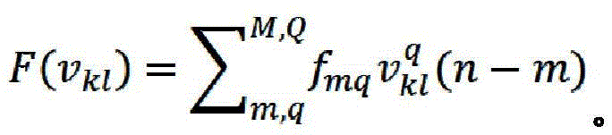
Fig. 2B illustrates an example architecture of a first nonlinear filter network in accordance with some embodiments. In some embodiments, the first nonlinear filter network 210 may includeAn absolute value block 252, correction elements 254A, 254B, 254N, a plurality of stages (1 to N)256A, 256B, 256N, an adder 258, and a multiplier 260. Each stage 256A, 256B, 256N may include multiple (1 to M) nonlinear filters. Each (or at least some) of the 1 to M filters may include a first non-linear Low Pass Filter (LPF)262A, 262B, 262N, and possibly one or more non-linear all- pass filters 264A, 264B, 264N, 266A, 266B, 266N. For each stage 256A, 256B, 256N, the LPF and possibly one or more all-pass filters may be arranged in series. The LPF filter may receive the signal, process the signal through the LPF, output the signal to a series of all-pass filters, and then process the signal through the all-pass filters. In some embodiments, the filters of the first nonlinear filter network are orthogonal to each other. For example, an LPF may allow signals with frequencies below a certain cutoff frequency to pass through the LPF, while a subsequent all-pass filter may allow signals to pass only phase modifications with little or no effect on amplitude. Non-linear function F (v) in FIGS. 2b and 3kl) May include vklOf stored polynomial expansion, e.g.
In some embodiments, the stages 256A, 256B, 256N (e.g., 1 to M filters, each stage may include an LPF and possibly one or more all-pass filters) are arranged in parallel with each other. In some embodiments, each of the 1 to M filters includes a correction element, described in further detail herein. Each of the stages 256A, 256B, 256N may account for a different time constant because charge trap distortion may occur in multiple responses over various time ranges.
In some embodiments, a complex baseband signal is received from a digital up-converter (x), which may include in-phase and quadrature-phase (I/Q) signals. The apparatus generates the envelope of the signal by determining the absolute signal of the complex baseband signal via the absolute value block 252. For example, coordinate rotation digital computation (CORDIC) circuitry may be used to process digital I and digital Q data to generate a digital envelope. The absolute value block 252 outputs the envelope of the signal.
In some embodiments, the device propagates the output of the absolute value block 252 to a plurality of correction elements 254A, 254B, 254N. The plurality of correction elements 254A, 254B, 254N introduce non-linearity into the signal. For example, a plurality of correction elements (e.g., 1 to N correction elements) 254A, 254B, 254N may be indexed to the output of the absolute value block 252. The first correction element 254A may take 1 times the output of the absolute value block 252. The second correction element 254B may take 2 times the output of the absolute value block 252. The N correction elements 254N may take N exponentials of the output of the absolute value block 252. For example, fig. 2B shows that the output of the absolute value block 252 (e.g., | |) is sent to three correction elements 254A, 254B, 254N. The first correction element 254A takes an index (()1) The exponent is substantially the same as the output of the absolute value block 252. The output is sent to a first plurality of nonlinear laguerre filters 256A. The second correcting element 254B takes an index (()2) And sends the output to a second plurality of nonlinear laguerre filters 256B. The third correction element 254N may take the nth index (()n) And sends the output to a third plurality of nonlinear laguerre filters 256N. Thus, the correction elements 254A, 254B, 254N have the nonlinear capability of an envelope.
In some embodiments, the outputs of the 1 to N correction elements 254A, 254B, 254N are propagated to a corresponding 1 to N plurality of nonlinear filters 256A, 256B, 256N, e.g., 1 to N laguerre filters. The first filter 262A, 262B, 262N may comprise a low pass filter and the remaining filters 264A, 264B, 264N, 266A, 266B, 266N may comprise all-pass filters. The following are digital representations of the Low Pass Filter (LPF) and the all pass filter (BPF). The number of stages 0: LPF, the
the stages 1 to L, BPF,

a1is the filter coefficient, FsIs the sampling rate (e.g., in the 100MHz range), and τ is the time constant of the charge trapping effect (e.g., microseconds, milliseconds). The time constant may be determined by looking at the charge trapping effect of the power amplifier. Then, a can be determined1The filter coefficients.
In some embodiments, the outputs of the 1 to N plurality of nonlinear filters 256A, 256B, 256N are added by an adder 258 to generate the low frequency gain term glag. Low frequency gain term glagRepresenting a narrow band frequency correction gain.
In some embodiments, the low frequency gain term glagMultiplied by the complex baseband signal input through the multiplier 260 to generate a correction signal to correct the charge trapping effect ulag。
In some embodiments, the first nonlinear network and/or the second nonlinear network are implemented at least in part in software (e.g., by a digital signal processor as an all-digital solution). In some embodiments, the first non-linear network and/or the second non-linear network are implemented at least in part in firmware.
Example architecture of a first non-linear filter network with decimation and upsampling
Fig. 3 illustrates an architecture of a first nonlinear filter network including decimation and upsampling functions according to some embodiments. Decimation enables processing of hundreds of megahertz of data in the device circuitry. Processing of such data may require very expensive components and require a significant amount of processing power if no decimation is performed.
In some embodiments, the digital up-converter 302 may feed a signal to the first nonlinear filter network 314. The first nonlinear filter network 314 may include an absolute value module 316 and a decimator, such as a cascaded integrator-comb (CIC) filter 318. The signal from the digital up-converter 302 may be processed by an absolute value block 316. The CIC filter 318 may decimate the output of the absolute value block 316 and send the output to 1 to N nonlinear filters 322, such as 1 to N laguerre filters. Decimation enables the architecture to reduce the data rate (e.g., by 100 orders of magnitude) to create an efficient and practical architecture in the actuator.
In some embodiments, summer 258 may sum the outputs of 1 to N nonlinear filters 322 to produce low frequency gain term glag. The low frequency gain term may be upsampled via an upsampler 324, such as a CIC filter, to interpolate the signal back to its original sampling frequency. Delay match 320 may match the signal from the output of digital up-converter 302 to the output of up-converter 324, and the output of delay match 320 (complex baseband input time matched to the output of the first nonlinear filter network) may be multiplied by the output of up-converter 302 by multiplier 312. Delay matching blocks (e.g., delay matching 320) are used to compensate for delays in processing data through various blocks (e.g., CIC filters).
In some embodiments, the digital up-converter 302 may also feed the signal to a second nonlinear filter network 304. The output of the second nonlinear filter network 314 may be delay matched with the output of the first nonlinear filter network 304 by a delay match 312. The output of the delay match 312 may be added to the output of the second nonlinear filter network 304 through the summer 306, and the output of the summer 306 may be input to the power amplifier 310.
Example architecture for a first non-linear filter network including crest factor reduction functionality
Fig. 4 illustrates an example architecture of a first nonlinear filter network including a crest factor reduction function, a first delay block, and a second delay block, in accordance with some embodiments. 4G/5G transmitters typically use a Crest Factor Reduction (CFR) function. The 4G/5G transmitter may be included in a user equipment (e.g., a mobile device). The 4G/5G transmitter may be included in a base station. The CFR function may include removing peaks from the envelope of the input signal to avoid or mitigate saturation in the power amplifier. However, the CFR function results in a long delay because the signal takes a lot of time to propagate through the CFR function. Furthermore, the decimator and upsampler (e.g., CIC) also have delays that together result in a significant delay. However, if the signal is to be delayed by the CFR function and the decimator/upsampler, the total latency of the transmitter may be too large. To eliminate or mitigate this problem, some embodiments include sending the output of the digital up-converter directly to a component associated with the first nonlinear filter network, and processing the second nonlinear filter network with the output of the CFR function.
In some embodiments, the output of digital up-converter (DUC)402 may be processed by absolute value block 414. The absolute value block 414 outputs the envelope of the signal to a down-converter (e.g., CIC filter 416). The outputs of the CIC filters 416 are processed through nonlinear laguerre filters and summed by an adder 420. The output of the summer 420 is processed by an up-converter (e.g., CIC filter 422) to match the frequency of the signal provided by the DUC 402. In an alternative embodiment, the output of the digital up-converter (DUC)402 may be processed by the CFR function 404, and the output of the CFR function 404 may be input to the absolute value module 414.
In some embodiments, the output of DUC402 is processed by CFR function 404. The output of the CFR function 404 may be sent to a first delay matching block 426 that delays the output of the CFR function 404 to match the output of the upsampler CIC 422. The multiplier may then multiply the output of the CFR function 404 with the output of the CIC filter 422.
In some embodiments, the output of the CFR function 303 may also be sent to a second nonlinear filter network 406, such as a GMP filter. In some embodiments, the second delay block 430 delays the output of the multiplier 428 to match the output of the second nonlinear filter network 406, such as a GMP filter. The output of the second delay block 430 may then be added to the output of the second nonlinear filter network 406 by an adder 408. The output of the summer 408 may then be sent to a power amplifier 412.
In some embodiments, the delay blocks, e.g., first and/or second delay blocks 426, 430, include one or more shift registers. The shift registers may be connected in series.
Example architecture for training first and second nonlinear filter networks through direct learning algorithm
Fig. 5 illustrates an example architecture of an RF semiconductor device for training first and second nonlinear filter networks through a direct learning algorithm, in accordance with some embodiments. The RF semiconductor device compares the observed output y of the power amplifier with the actual input signal x to generate an error signal. In this way, the direct learning algorithm can train the GMP actuator and then train the laquinier actuator using the input x and output y of the power amplifier 510. In an alternative embodiment, the GMP and laquinier actuators may be trained using an indirect learning algorithm, for example by using the difference between the input u of the power amplifier 510 (which is the combined signal of the GMP actuator 504 and the nonlinear Laguerre actuator 506 through the adder 508) and applying the same DPD (GMP and Laguerre) function to the power amplifier 510, y.
In some embodiments, the summer 514 outputs the difference between the input x to the system and the output y of the power amplifier. The difference is sent to a direct learning algorithm 512, which determines an error signal from the difference value. The system may then train the GMP actuator 504 and the Laguerre actuator 506, respectively. The system may process the input signal x and collect data (e.g., the output of the CFR block 502 and the output of the power amplifier y) to train the GMP actuator 504. The system may then switch the state machine to establish a system of equations to train Laguerre actuator 506.
Fig. 6 illustrates an example architecture for training a GMP actuator, in accordance with some embodiments. Fig. 7 illustrates an example architecture for training a laguerre actuator, according to some embodiments.
As shown in fig. 6 and 7, the RF semiconductor device may train a GMP actuator and a Laguerre actuator. The RF semiconductor device may perform a partial update on the GMP actuator (e.g., by using the architecture of fig. 6), then perform a partial update on the Laguerre actuator (e.g., by using the architecture of fig. 7), and then repeatedly perform the partial updates of the GMP and Laguerre actuators. Further, in the case of a training Laguerre actuator, the RF semiconductor device may down-sample the training vectors, allowing for a shallower training buffer to be used to capture the training vectors and capture data over an extended range. For example, a 4k shallow training buffer may be sampled at a 500MHz sampling frequency and then provide an effective buffer depth of 8 us.
The signal from the digital up-converter 402 may be processed by a CFR function 404, the output of the CFR function 404 may be processed by a second nonlinear filter network 406, and the output of the summer 408 may be input to a power amplifier 412.
In fig. 6, the output of the CFR function 404 and the output of the power amplifier 412 are employed to train the GMP actuator. The output of the CFR function 404 is processed by a delay matching block 614 to match the delay between the output of the CFR function 404 and the output of the power amplifier 412. The output of the delay matching block 614 and the output of the power amplifier 412 fill the respective capture buffers 612, 604, respectively. The time alignment block 606 aligns the outputs of the capture buffers 612, 604. Such time alignment may help compensate for the rate difference between the samples captured at the output of the power amplifier 412 (at RF frequencies) and the samples captured at the output of the CFR 404 (at baseband frequencies). In some embodiments, the delay matching block 614 may align the outputs within a particular precision window. The delay matching block 614 may be a preconfigured delay. The time alignment block 606 may further delay the signal by tracking time variations in the delay, such as analog circuit based delays that vary based on process, power, temperature, and/or aging. The time alignment block 606 may be dynamic, adjusting based on tracking of time changes.
System build matrix X of GMP features 610gmpWhich may include both linear and non-linear terms. The GMP features are sent to a correlation engine 618 to process the GMP features. Correlation engine 618 can determine feature XgmpAnd the error vector εgmpCross correlation vector r betweengε and an autocorrelation matrix RgmpFor application to partial update block 616, partial update block 616 may include a solver, such as a least squares solver. Partial update block 616 may be furtherThe actuator is new and the training can repeat again and/or continue to train the laguer actuator.
In some embodiments, the system may cycle the process multiple times. The system may capture another buffer of output data from the CFR function 404 and output data from the power amplifier 412, generate GMP characterization, determine errors, and generate another cross-correlation vector that may be added to the previous corrected sum.
In fig. 7, the output of the CFR function 404 and the output of the power amplifier 412 are used to train the laguerre actuator. The output of CIC down sampler 416, which may include the envelope of the input signal decimated to a lower sampling rate, may be used in Laguerre actuator training. The output may be delayed by a delay matching block 724 and a time alignment block 726 may time align the output of the delay matching block 724 to match the time aligned set of the time alignment block 708. The time-aligned signal is sent to the capture buffer 728 and then to the laguerre feature block 730 to generate the laguerre features. The capture buffer is approximately 5, 10, 50, 100, 500 samples in length. Because the signal has been down-sampled at the output of CIC down-sampler 416, the signal captured at the capture buffer captures data long enough that samples can be taken by the charge and/or discharge curves. As discussed herein, the time constant effects of charging and discharging, such as in fig. 1C, include narrow-band distortion over a longer period of time than typical digital predistortion.
In some embodiments, Laguerre characteristics 730 are sent to correlation engine 734 to process GMP characteristics to determine cross-correlation vector rlε and an autocorrelation matrix RlagAnd a partial update module 732, such as a least squares solver. The laguer feature 730, the correlation engine 734, and/or the partial update module 732 may be implemented in software, firmware, and/or a combination.
In some implementations, the initial conditions (e.g., v) of the nonlinear laguerre filter 4180) For training a laguerre actuator. The initial condition is to prevent transient effects in the system of equations from affecting other variables and equations, therebyLeading to erroneous results and solutions. In some embodiments, the initial state or condition may be predetermined. This method can be used for systems with one or two cascaded laguerre filters. However, if the system has three, four, five or more cascaded laguerre filters, the system of equations becomes complex and the charge trap correction becomes increasingly incorrect under assumed initial conditions.
To mitigate or eliminate the above-described deficiencies, some embodiments disclose taking actual initial state readings from a laguerre filter actuator. The initial condition of the nonlinear Laguerre filter 418 is delayed by a delay matching block 718 and a time alignment block 720 may time align the output of the delay matching block 718. The capture buffer 722 may capture samples of initial conditions, which may be sent to the laguerre features block 730 to generate laguerre features based on the production of the matrix of laguerre entries. The initial conditions and initial states of the nonlinear laguerre filter 418 are further described with reference to fig. 8.
In some implementations, the difference between the output of the CFR function 404 and the power amplifier 412 is used to train the laguer actuator. Similar to the embodiment of fig. 6, the output of CFR function 404 is delay matched 714 and stored in capture buffer 716. The output of the power amplifier 412 is also stored in a capture buffer 706. The outputs of the capture buffers 706, 716 are time aligned 708 and the difference via adder 710 is sent to a correlation engine 734 to determine a cross correlation vector rlε and an autocorrelation matrix Rlag。
In some implementations, the output of the CFR function 404 is downsampled by N via a downsampler 712. The down sampler 712 may down sample the output of the CFR function 404 to match the decimation rate of the envelope (e.g., the output of block 416). For example, the downsampler may have one input per 100 samples. In some embodiments, the output of the power amplifier 412 is downsampled M via the downsampler 704. The down sampler 704 may down sample the output of the power amplifier 412 to match the decimation rate of the envelope (e.g., the output of block 416). Thus, the inputs to the two capture buffers 716 and 706 may be at matching sample rates. In some embodiments, a downsampler is used instead of a decimation filter, because the downsampled signal is used to fit a model (rather than a reconstructed signal) in the correlation engine 734. Advantageously, the capture buffer can see the data for a longer period of time. For example, if the capture buffer can only capture 10,000 samples for a long time, and the downsampled factor is 100, then the capture buffer can now expand the 10,000 samples by a factor of 100. Thus, if only the capture buffer sees 1 microsecond of data, the capture buffer with downsampling can now hold more than 10 milliseconds of data. This down-sampling enables the system to capture narrow-band, slower transient effects.
In some embodiments, training for the GMP actuator (e.g., fig. 6) and training for the Laguerre actuator (e.g., fig. 7) occur in series and/or not at the same time. Thus, the capture buffer can be reused. For example, the system may turn on the power supply of the power amplifier and other hardware, capture data and train the GMP actuator, capture data and train the Laguerre actuator, and then repeat the training twice. Advantageously, the system may be smaller and use fewer components due to the reuse of certain components.
Determining initial conditions for Laguerre actuator training
Fig. 8 illustrates an example architecture for identifying initial conditions for laguerre actuator training, in accordance with some embodiments. The laguerre actuator 822 receives the signal, generates an envelope of the signal via the absolute value block 824, applies a non-linear correction (e.g., by applying power to the signal (e.g., signal squared or cubed)) via the correction element 826, and passes the signal through laguerre filters 828, 830, 832. One or more Laguerre filters may contain an autoregressive term, where the output of each filter is delayed by a TX-ORX delay 820 and fed into Laguerre training model 801 in a feedback loop. The term fed is the initial stage used in the Laguerre training model 801. The laguerre training model then receives the signal and again generates an envelope of the signal by the absolute value block 802, with non-linear correction by the correction element 804 (e.g., by applying work to the signal)Rate, e.g., signal squared or cubed), and then passes the signal through Laguerre filters 806, 808, 810. However, Laguerre filters 806, 808, 810 of Laguerre training model 801 receive initial conditions, which are weighted by equations 812, 816 and adders 814, 818. v. ofklDPD is the actuator internal state. DPD is the internal state of the training model. v. ofkl(n-D)=vklz-DIs the previous internal state of the Laguerre filter. z is a radical of-DIs a time delay.
 Stage 0 initialization for Laguerre actuator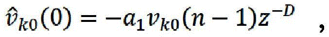 The rest of the stages are initialized to
 The term
 For generating Laguerre features as described herein with respect to fig. 7.
Simultaneous training of GMP and Laguerre actuators
Fig. 9 illustrates an example architecture for an RF semiconductor device to train both GMP and laguerre actuators simultaneously, in accordance with some embodiments. In some embodiments, the RF semiconductor device may use the architecture to train the Laguerre actuator without downsampling. The RF semiconductor device may capture data from the Laguerre actuator for a long time. The capture buffer will capture more data for a longer time than the buffer of the previous figure. For example, an RF semiconductor device may capture hundreds of megahertz of data that may fill a buffer and train within a data window of tens of microseconds. The RF semiconductor device may then train the Laguerre actuator over and over again, effectively scanning the millisecond data window. In some embodiments, the sampling frequency may be between 10-500 MHz. In some embodiments, the lagrange actuators can be trained in a time range of 100 nanoseconds to 1 millisecond, 1 millisecond to 10 milliseconds, and so on.
The output of the nonlinear laguerre filter 418, the CFR function 404 and the output of the power amplifier 412 are taken and aligned by delay matching blocks 910, 902 and time alignment blocks 912, 906. The capture buffers 904, 908 capture data. The difference between the output of the CFR function 404 and the output of the power amplifier 412 is determined via an adder 909. The difference signal from adder 909 is sent to GMP feature generator 916, Laguerre feature generator 914, and CIC delay matching block 918. Laguerre feature generator 914 also receives initial conditions from time alignment block 912. The GMP feature generator 916 and Laguerre feature generator 914 generate respective polynomials and send the polynomials to the correlation engine 924. The correlation engine 618 may determine a cross-correlation vector r for the GMP actuatorgε and an autocorrelation matrix RgmpAnd cross-correlation vector r for Laguerre actuatorlε and an autocorrelation matrix Rlag. The laguerre internal state 920 is an initialization function described above with reference to fig. 8, wherein the internal state of the actuator is identified and converted into the initial state of the laguerre adaptation.
Correcting low and wide band distortion using two non-linear filter networks
Fig. 10 illustrates an RF semiconductor device according to some embodiments, including: a first nonlinear filter network comprising a FIR filter for correcting narrow band distortion; and a second nonlinear filter network for a FIR filter correcting the wide-band distortion. The first nonlinear filter network 1012 may include a first nonlinear actuator and the second nonlinear filter may include a second nonlinear actuator 1014. The first nonlinear filter network 1012 may be connected in parallel with the second nonlinear filter network 1014. The first nonlinear filter network 1012 may include a GMP actuator, a laguerre actuator, and/or the like. The second nonlinear filter network 1014 may include a GMP actuator, a laguerre actuator, and/or the like. The outputs of the first nonlinear filter network 1012 and the second nonlinear filter network 1014 may be added by an adder 1016 and the combined signal may be sent to the power amplifier 1002.
In some embodiments, the device may further include a feedback actuator 1008 that further includes a first nonlinear filter network 1018 in parallel with a second nonlinear filter network 1020. The feedback actuator 1008 may receive the input and output of the power amplifier 1002 for fitting the inverse model. The output of the power amplifier 1002 may be fed to another first non-linear filter network 1018 and another second non-linear filter network 1020. The adder 1022 adds the outputs of the further first nonlinear filter network 1018 and the further second nonlinear filter network 1020. The input of power amplifier 1002 is then subtracted from the output of summer 1022 via another summer 1010. The output of the summer 1010 is processed by a least squares module 1006. The output of the least squares module 1006 is used by a second other non-linear filter network 1018. The system may use other solvers besides the least squares module 1006.
In some embodiments, the first nonlinear filter network 1012 may have a sampling rate to correct for narrow-band distortion by capturing samples under a longer time constraint. The second nonlinear filter network 1014 may have to have a higher sampling rate to correct for higher frequency noise.
Example embodiments compensate for ramp-up of a power amplifier
The power amplifier may exhibit different performance characteristics immediately after power-up (e.g., immediately after being enabled) relative to steady-state operation after the power amplifier is stabilized. The effect of such a power amplifier may be caused by various factors, such as self-heating of the power amplifier. For example, the initial operation of the power amplifier upon cooling may vary with respect to operation of the power amplifier after it reaches a steady state operating temperature.
In some applications, the power amplifier may be turned on for a long period of time and then turned off for a long period of time. For example, for a base station or mobile device using Time Division Duplexing (TDD), the power amplifier may be turned on in the transmit time slot and turned off in the receive time slot.
The DPD system herein can be implemented to compensate for transient changes in power amplifier performance after turn-on and steady state. For example, any of the embodiments herein may be used to store multiple sets of coefficients for a DPD (including coefficients for a charge trapping DPD). In addition, the DPD system may be configured to use one set of coefficients shortly after turning on the power amplifier (e.g., within a time period T after the power amplifier is turned on) and to use a second set of coefficients in steady state (e.g., after the time period T).
By using two (or more) sets of coefficients for the DPD, the power amplifier can be more effectively linearized, including the power amplifier for initial or start-up operation as well as for steady-state operation.
Any of the embodiments herein may be implemented with multiple sets of DPD coefficients, the selection of which depends on how long the power amplifier has been on/enabled.
Additional embodiments
In the foregoing, it will be appreciated that any feature of any one of the embodiments may be combined with or substituted for any other feature of any other of the embodiments.
Aspects of the present disclosure may be implemented in various electronic devices. Examples of electronic devices may include, but are not limited to, consumer electronics, a portion of consumer electronics, electronic test equipment, cellular communication infrastructure such as a base station, and the like. Examples of electronic devices may include, but are not limited to, mobile phones such as smart phones, wearable computing devices such as smart watches or headsets, telephones, televisions, computer monitors, computers, modems, handheld computers, laptop computers, tablets, Personal Digital Assistants (PDAs), microwave ovens, refrigerators, automotive electronic systems (e.g., car electronic systems), stereos, DVD players, CD players, digital music players (e.g., MP3 players), radios, camcorders, cameras such as digital cameras, portable memory chips, washing machines, dryers, washing/drying machines, peripherals, clocks, and the like. Further, the electronic device may include unfinished products.
Unless the context clearly requires otherwise, throughout the description and the claims, the words "comprise," "comprising," "have," "having," and the like are to be construed in an inclusive sense as opposed to an exclusive or exhaustive sense; that is, in the sense of "including, but not limited to". The term "coupled," as generally used herein, refers to two or more elements that may be connected directly or through one or more intermediate elements. Likewise, the term "connected," as generally used herein, refers to two or more elements that may be connected directly or through one or more intermediate elements. Additionally, the words "herein," "above," "below," and words of similar import, when used in this application, shall refer to this application as a whole and not to any particular portions of this application. Where the context permits, words in the above detailed description using the singular or plural number may also include the plural or singular number respectively. The word "or" refers to a list of two or more items that encompasses all of the following interpretations of the word: any item in the list, all items in the list, and any combination of items in the list.
Furthermore, conditional language, e.g., "can," might, "" e.g., "such as" used herein, is generally intended to convey that certain embodiments include but not certain features, elements, and/or states unless specifically stated otherwise, or otherwise understood in the context in which it is used. Thus, such conditional language is not generally intended to imply that features, elements, and/or states are in any way required for one or more embodiments or that these features, elements, and/or states are included or are to be performed in any particular embodiment.
While certain embodiments have been described, these embodiments have been presented by way of example only, and are not intended to limit the scope of the disclosure. Indeed, the novel apparatus, methods, and systems described herein may be embodied in a variety of other forms. Furthermore, various omissions, substitutions and changes in the form of the methods and systems described herein may be made without departing from the spirit of the disclosure. For example, while blocks are presented in a given arrangement, alternative embodiments may perform similar functions with different components and/or circuit topologies, and some blocks may be deleted, moved, added, subdivided, combined, and/or modified. Each of these blocks may be implemented in a variety of different ways. Any suitable combination of the elements and acts of the various embodiments described above can be combined to provide further embodiments. The various features and processes described above may be implemented independently of one another or may be combined in various ways. All possible combinations and sub-combinations of the features of the present disclosure are intended to fall within the scope of the present disclosure.
Claims (20)
1. A Radio Frequency (RF) power semiconductor device, wherein the device comprises:
a first non-linear filter network configured to compensate for narrowband distortion of a power amplifier, wherein the first non-linear filter network comprises a correction element configured to correct for a non-linear portion of the power amplifier; and
a second non-linear filter network configured to compensate for wideband distortion of the power amplifier.
2. The device of claim 1, wherein the first nonlinear filter network comprises a first plurality of Infinite Impulse Response (IIR) filters arranged in series.
3. The device of claim 2, wherein a first filter of the first plurality of IIR filters comprises a Low Pass Filter (LPF).
4. The device of claim 3, wherein a second filter of the first plurality of IIR filters comprises an all-pass filter.
5. The device of claim 2, wherein the first plurality of IIR filters are orthogonal to each other.
6. The device of claim 1, wherein the first non-linear filter network includes N sets of IIR filters, wherein each of the N sets of IIR filters has M IIR filters arranged in series, wherein the N sets of IIR filters are arranged in parallel.
7. The device of claim 6, further comprising 1 to N correction elements corresponding to the N sets of IIR filters, wherein the 1 to N correction elements correct for a non-linear portion of the power amplifier before the correction signal propagates through the corresponding N sets of IIR filters.
8. The device of claim 7, wherein the correction of the non-linear portion of the power amplifier comprises applying an exponential to the amplitude of the signal for each of the 1 to N correction elements.
9. The device of claim 1, wherein the device further comprises:
a power amplifier, wherein the power amplifier comprises a compound semiconductor power amplifier, an
The narrow-band distortion is caused by a charge trapping effect when the compound semiconductor power amplifier is charged from low power to high power.
10. The device of claim 9, wherein the compound semiconductor power amplifier comprises a gallium nitride (GaN) power amplifier.
11. The device of claim 1, further comprising:
a down-sampler for down-sampling an input signal and transmitting the down-sampled signal to the first nonlinear filter network; and
an upsampler to upsample an output of the first nonlinear filter network.
12. The device of claim 1, further comprising:
a mixer that mixes an output of the first nonlinear filter network with an input of the first nonlinear filter network; and
a first buffer configured to delay an input of the first nonlinear filter network to match a timing of the signal with an output of the first nonlinear filter network.
13. The device of claim 12, further comprising: a second buffer configured to delay an output of the mixer from the output to match the timing with an output of the FIR filter.
14. The device of claim 1, wherein the second nonlinear filter network comprises a plurality of Finite Infinite Response (FIR) filters.
15. The device of claim 1, wherein the first nonlinear filter network comprises a laguerre filter.
16. A Radio Frequency (RF) power semiconductor device, wherein the device comprises:
a first non-linear filter network configured to compensate for narrow-band distortion of a power amplifier, wherein the first non-linear filter network comprises a plurality of Infinite Impulse Response (IIR) filters and corresponding correction elements for correcting a non-linear portion of the power amplifier.
17. The device of claim 16, wherein the plurality of IIR filters comprises laguerre filters.
18. The device of claim 16, wherein the device further comprises:
a crest factor reduction function; and
a second non-linear filter network configured to compensate for wideband distortion of the power amplifier, wherein the crest factor reduction function is in series with the second non-linear filter network.
19. The device of claim 18, wherein the second nonlinear filter network comprises a plurality of Finite Infinite Response (FIR) filters.
20. A Digital Predistortion (DPD) method, comprising:
amplifying the transmit signal using a power amplifier;
compensating for narrow-band distortion of the power amplifier by pre-distorting the transmit signal using a first non-linear filter network, including correcting a non-linear portion of the power amplifier using a correction element of a first non-linear filter; and
compensating for wideband distortion of the power amplifier by pre-distorting the transmit signal using a second non-linear filter network.
Applications Claiming Priority (4)
| Application Number | Priority Date | Filing Date | Title |
|---|---|---|---|
| US201962952757P | 2019-12-23 | 2019-12-23 | |
| US62/952,757 | 2019-12-23 | ||
| US17/099,107 | 2020-11-16 | ||
| US17/099,107 US11533070B2 (en) | 2019-12-23 | 2020-11-16 | Systems and methods of compensating for narrowband distortion in power semiconductor devices |
Publications (2)
| Publication Number | Publication Date |
|---|---|
| CN113098406A true CN113098406A (en) | 2021-07-09 |
| CN113098406B CN113098406B (en) | 2024-08-09 |
Family
ID=73789983
Family Applications (1)
| Application Number | Title | Priority Date | Filing Date |
|---|---|---|---|
| CN202011537629.1A Active CN113098406B (en) | 2019-12-23 | 2020-12-23 | System and method for compensating narrowband distortion in power semiconductor devices |
Country Status (3)
| Country | Link |
|---|---|
| US (1) | US11533070B2 (en) |
| EP (1) | EP3843267B1 (en) |
| CN (1) | CN113098406B (en) |
Cited By (2)
| Publication number | Priority date | Publication date | Assignee | Title |
|---|---|---|---|---|
| CN119294311A (en) * | 2024-12-13 | 2025-01-10 | 北京航天驭星科技股份有限公司 | Shaping filter and coefficient generation method, device, medium and program product thereof |
| CN120950894A (en) * | 2025-10-15 | 2025-11-14 | 成都虹润制漆有限公司 | In-situ non-destructive assessment method for coating aging based on photoacoustic spectroscopy |
Families Citing this family (6)
| Publication number | Priority date | Publication date | Assignee | Title |
|---|---|---|---|---|
| US11533070B2 (en) | 2019-12-23 | 2022-12-20 | Analog Devices International Unlimited Company | Systems and methods of compensating for narrowband distortion in power semiconductor devices |
| US11563409B2 (en) * | 2020-10-26 | 2023-01-24 | Analog Devices International Unlimited Company | Configurable non-linear filter for digital pre-distortion |
| US11483018B1 (en) * | 2021-06-04 | 2022-10-25 | Xilinx, Inc. | Reconfigurable and scalable nonlinear filter for digital pre-distorters |
| EP4360211A1 (en) * | 2021-06-24 | 2024-05-01 | Analog Devices International Unlimited Company | Systems and methods of compensating a transmit signal for charge trapping effects of a power amplifier |
| US12231143B2 (en) | 2021-12-06 | 2025-02-18 | Analog Devices International Unlimited Company | Radio transmitter providing an analog signal with both radio frequency and baseband frequency information |
| US20230179455A1 (en) * | 2021-12-07 | 2023-06-08 | Meta Platforms, Inc. | Multi-stage sequential pim reduction via sequential training |
Citations (8)
| Publication number | Priority date | Publication date | Assignee | Title |
|---|---|---|---|---|
| US20020178138A1 (en) * | 2001-03-15 | 2002-11-28 | Semiconductor Components Industries, Llc | Synergistic directory-based information management system and method of using |
| CN1689295A (en) * | 2002-10-31 | 2005-10-26 | 中兴通讯股份有限公司 | Broadband predistortion linearization method and system |
| CN101720528A (en) * | 2007-04-23 | 2010-06-02 | 大力系统有限公司 | Digital hybrid mode power amplifier system |
| US20110255628A1 (en) * | 2008-01-09 | 2011-10-20 | Sprint Spectrum L.P. | Method And Apparatus For Interference Mitigation By Removing A Portion Of The Transmit Signal |
| CN103685108A (en) * | 2012-09-05 | 2014-03-26 | 美国亚德诺半导体公司 | System and method to implement a radio transmitter with digital predistortion having reduced noise |
| CN104883140A (en) * | 2015-06-03 | 2015-09-02 | 中国科学院微电子研究所 | Digital predistortion device based on broadband radio frequency power amplifier |
| US9866269B1 (en) * | 2016-11-17 | 2018-01-09 | Xilinx, Inc. | Method of and circuit for predistortion for a power amplifier |
| US20190356345A1 (en) * | 2018-05-17 | 2019-11-21 | Fujitsu Limited | Distortion compensation device and distortion compensation method |
Family Cites Families (46)
| Publication number | Priority date | Publication date | Assignee | Title |
|---|---|---|---|---|
| US6453308B1 (en) * | 1997-10-01 | 2002-09-17 | Aspen Technology, Inc. | Non-linear dynamic predictive device |
| US6298097B1 (en) | 1999-05-11 | 2001-10-02 | Wiseband Communications Inc. | Amplifier with wideband digital predistortion |
| US6828858B2 (en) | 2002-04-12 | 2004-12-07 | The Regents Of The University Of California | CMOS class AB power amplifier with cancellation of nonlinearity due to change in gate capacitance of a NMOS input transistor with switching |
| US7149257B2 (en) | 2003-07-03 | 2006-12-12 | Powerwave Technologies, Inc. | Digital predistortion system and method for correcting memory effects within an RF power amplifier |
| US7330517B2 (en) | 2003-11-24 | 2008-02-12 | P-Wave Ltd. | Amplifier linearization using non-linear predistortion |
| KR101058733B1 (en) | 2004-01-02 | 2011-08-22 | 삼성전자주식회사 | Precompensation Device Compensates for Nonlinear Distortion Characteristics of Power Amplifiers |
| US7366252B2 (en) | 2004-01-21 | 2008-04-29 | Powerwave Technologies, Inc. | Wideband enhanced digital injection predistortion system and method |
| US7577211B2 (en) | 2004-03-01 | 2009-08-18 | Powerwave Technologies, Inc. | Digital predistortion system and method for linearizing an RF power amplifier with nonlinear gain characteristics and memory effects |
| US7606322B2 (en) | 2004-10-07 | 2009-10-20 | Microelectronics Technology Inc. | Digital pre-distortion technique using nonlinear filters |
| CN100563225C (en) | 2005-05-27 | 2009-11-25 | 华为技术有限公司 | Universal device for predistortion processing of baseband digital signals |
| US7729446B2 (en) | 2006-12-01 | 2010-06-01 | Texas Instruments Incorporated | System and method for digitally correcting a non-linear element using a multiply partitioned architecture for predistortion |
| US7773692B2 (en) | 2006-12-01 | 2010-08-10 | Texas Instruments Incorporated | System and methods for digitally correcting a non-linear element using a digital filter for predistortion |
| US7822146B2 (en) | 2006-12-01 | 2010-10-26 | Texas Instruments Incorporated | System and method for digitally correcting a non-linear element |
| US9705477B2 (en) | 2008-04-30 | 2017-07-11 | Innovation Digital, LLC | Compensator for removing nonlinear distortion |
| JP5241921B2 (en) | 2008-07-29 | 2013-07-17 | ドルビー ラボラトリーズ ライセンシング コーポレイション | Methods for adaptive control and equalization of electroacoustic channels. |
| JP2011176689A (en) | 2010-02-25 | 2011-09-08 | Fujitsu Ltd | Calculating apparatus, distortion correcting apparatus, amplifying apparatus, and calculating method |
| KR101102465B1 (en) * | 2010-05-03 | 2012-01-05 | 한국과학기술원 | Digital Predistortion Apparatus and Method for Broadband Power Amplifier |
| US9363068B2 (en) | 2010-08-03 | 2016-06-07 | Intel Corporation | Vector processor having instruction set with sliding window non-linear convolutional function |
| US8410843B2 (en) | 2011-01-10 | 2013-04-02 | Massachusetts Institute Of Technology | Polyphase nonlinear digital predistortion |
| TWI556597B (en) * | 2011-03-31 | 2016-11-01 | Panasonic Corp | Wireless communication device |
| US8537041B2 (en) | 2011-05-12 | 2013-09-17 | Andrew Llc | Interpolation-based digital pre-distortion architecture |
| US9374044B2 (en) | 2011-12-21 | 2016-06-21 | Telefonaktiebolaget L M Ericsson (Publ) | Architecture of nonlinear RF filter-based transmitter |
| US8798559B2 (en) | 2012-02-28 | 2014-08-05 | Telefonaktiebolaget L M Ericsson (Publ) | FIR/IIR filter predistorter for power amplifiers exhibiting short-term and/or long-term memory effects |
| CN102893399B (en) | 2012-05-24 | 2015-09-09 | 华为技术有限公司 | Predistortion correction method, predistortion correction device, transmitter and base station |
| US9413298B2 (en) | 2012-12-28 | 2016-08-09 | Peregrine Semiconductor Corporation | Amplifier dynamic bias adjustment for envelope tracking |
| KR102065114B1 (en) | 2013-03-14 | 2020-01-10 | 삼성전자주식회사 | Operating method of reducing current collapse of power device |
| US9276617B2 (en) | 2013-03-15 | 2016-03-01 | Analog Devices, Inc. | Radio frequency domain digital pre-distortion |
| KR102112299B1 (en) | 2014-01-10 | 2020-05-18 | 삼성전자주식회사 | Driving method and driving circuit for power switching device |
| US9735741B2 (en) | 2014-08-28 | 2017-08-15 | Analog Devices Global | Receivers for digital predistortion |
| US9306506B1 (en) | 2014-11-24 | 2016-04-05 | Analog Devices Global | Apparatus and methods for dual loop power amplifier digital pre-distortion systems |
| US10324169B2 (en) | 2015-04-06 | 2019-06-18 | The United States Of America As Represented By The Secretary Of The Navy. | Digital compensation for amplifier-induced instability |
| EP3425794B1 (en) | 2015-06-17 | 2019-08-07 | Telefonaktiebolaget LM Ericsson (publ) | Least mean squares adaptation of a concurrent multi-band pre-distorter using overlapping spines |
| US9338039B1 (en) | 2015-08-26 | 2016-05-10 | Xilinx, Inc. | Efficient signal classification in digital pre-distortion systems |
| EP3166223B1 (en) | 2015-10-13 | 2020-09-02 | Analog Devices Global Unlimited Company | Ultra wide band digital pre-distortion |
| US9590668B1 (en) | 2015-11-30 | 2017-03-07 | NanoSemi Technologies | Digital compensator |
| US10033413B2 (en) | 2016-05-19 | 2018-07-24 | Analog Devices Global | Mixed-mode digital predistortion |
| US11082013B2 (en) | 2017-05-12 | 2021-08-03 | Mediatek Inc. | Method of reducing memory effect of power amplifier |
| WO2019070573A1 (en) | 2017-10-02 | 2019-04-11 | Nanosemi, Inc. | Digital predistortion adjustment based on determination of load condition characteristics |
| WO2019165621A1 (en) | 2018-03-01 | 2019-09-06 | Telefonaktiebolaget Lm Ericsson (Publ) | Envelope tracking supply modulator for power amplifier |
| US11387790B2 (en) * | 2019-01-24 | 2022-07-12 | Analog Devices International Unlimited Company | Power semiconductor device with charge trapping compensation |
| US10715702B1 (en) | 2019-03-12 | 2020-07-14 | Xilinx, Inc. | Method of and circuit for predistortion for a cable TV amplifier |
| US10763905B1 (en) | 2019-06-07 | 2020-09-01 | Micron Technology, Inc. | Wireless devices and systems including examples of mismatch correction scheme |
| US11533070B2 (en) | 2019-12-23 | 2022-12-20 | Analog Devices International Unlimited Company | Systems and methods of compensating for narrowband distortion in power semiconductor devices |
| US11108364B1 (en) | 2020-05-21 | 2021-08-31 | Xilinx, Inc. | System and method for digital pre-distortion circuits |
| US12003225B2 (en) | 2020-06-04 | 2024-06-04 | Intel Corporation | Method and apparatus for nonlinear signal processing |
| US11563409B2 (en) | 2020-10-26 | 2023-01-24 | Analog Devices International Unlimited Company | Configurable non-linear filter for digital pre-distortion |
-
2020
- 2020-11-16 US US17/099,107 patent/US11533070B2/en active Active
- 2020-12-09 EP EP20212838.5A patent/EP3843267B1/en active Active
- 2020-12-23 CN CN202011537629.1A patent/CN113098406B/en active Active
Patent Citations (8)
| Publication number | Priority date | Publication date | Assignee | Title |
|---|---|---|---|---|
| US20020178138A1 (en) * | 2001-03-15 | 2002-11-28 | Semiconductor Components Industries, Llc | Synergistic directory-based information management system and method of using |
| CN1689295A (en) * | 2002-10-31 | 2005-10-26 | 中兴通讯股份有限公司 | Broadband predistortion linearization method and system |
| CN101720528A (en) * | 2007-04-23 | 2010-06-02 | 大力系统有限公司 | Digital hybrid mode power amplifier system |
| US20110255628A1 (en) * | 2008-01-09 | 2011-10-20 | Sprint Spectrum L.P. | Method And Apparatus For Interference Mitigation By Removing A Portion Of The Transmit Signal |
| CN103685108A (en) * | 2012-09-05 | 2014-03-26 | 美国亚德诺半导体公司 | System and method to implement a radio transmitter with digital predistortion having reduced noise |
| CN104883140A (en) * | 2015-06-03 | 2015-09-02 | 中国科学院微电子研究所 | Digital predistortion device based on broadband radio frequency power amplifier |
| US9866269B1 (en) * | 2016-11-17 | 2018-01-09 | Xilinx, Inc. | Method of and circuit for predistortion for a power amplifier |
| US20190356345A1 (en) * | 2018-05-17 | 2019-11-21 | Fujitsu Limited | Distortion compensation device and distortion compensation method |
Non-Patent Citations (1)
| Title |
|---|
| ANDING ZHU: "RF power amplifier behavioral modeling using Volterra expansion with Laguerre functions", 《 IEEE MTT-S INTERNATIONAL MICROWAVE SYMPOSIUM DIGEST, 2005.》, pages 1 - 4 * |
Cited By (3)
| Publication number | Priority date | Publication date | Assignee | Title |
|---|---|---|---|---|
| CN119294311A (en) * | 2024-12-13 | 2025-01-10 | 北京航天驭星科技股份有限公司 | Shaping filter and coefficient generation method, device, medium and program product thereof |
| CN119294311B (en) * | 2024-12-13 | 2025-04-01 | 北京航天驭星科技股份有限公司 | Shaping filter and coefficient generation method, device, medium and program product thereof |
| CN120950894A (en) * | 2025-10-15 | 2025-11-14 | 成都虹润制漆有限公司 | In-situ non-destructive assessment method for coating aging based on photoacoustic spectroscopy |
Also Published As
| Publication number | Publication date |
|---|---|
| EP3843267A1 (en) | 2021-06-30 |
| US20210194521A1 (en) | 2021-06-24 |
| CN113098406B (en) | 2024-08-09 |
| US11533070B2 (en) | 2022-12-20 |
| EP3843267C0 (en) | 2025-03-05 |
| EP3843267B1 (en) | 2025-03-05 |
Similar Documents
| Publication | Publication Date | Title |
|---|---|---|
| CN113098406B (en) | System and method for compensating narrowband distortion in power semiconductor devices | |
| US11563409B2 (en) | Configurable non-linear filter for digital pre-distortion | |
| CN106572039B (en) | System and method for driving a load with a broadband signal | |
| US8854128B2 (en) | Amplifying device and signal processing device | |
| WO2007046370A1 (en) | Non-linear distortion detection method and distortion compensation amplification device | |
| US7792214B2 (en) | Polar modulation transmitter circuit and communications device | |
| WO2003017466A2 (en) | An adaptive pre-distortion method and apparatus for digital rf transmitters | |
| JP5708417B2 (en) | Amplifier | |
| EP4277127A1 (en) | Digital predistortion with neural-network-assisted physical modeling of envelope features | |
| JP7719895B2 (en) | System and method for compensating a transmit signal for charge trapping effects in a power amplifier | |
| US8437424B2 (en) | Robust transmit/feedback alignment | |
| US9065425B2 (en) | Feed-forward linearization without phase shifters | |
| US20220311462A1 (en) | Distortion compensation apparatus and distortion compensation method | |
| US20240305323A1 (en) | Digital pre-distortion corrector for power amplifier | |
| CN118631185A (en) | Digital Predistortion Corrector for Power Amplifiers | |
| JP2015220739A (en) | Distortion compensation apparatus and distortion compensation method | |
| Guan | FPGA-based Nonlinear Convolution | |
| van Bezooijen et al. | Adaptive RF Front-Ends |
Legal Events
| Date | Code | Title | Description |
|---|---|---|---|
| PB01 | Publication | ||
| PB01 | Publication | ||
| SE01 | Entry into force of request for substantive examination | ||
| SE01 | Entry into force of request for substantive examination | ||
| GR01 | Patent grant | ||
| GR01 | Patent grant |