CN113092588A - Ultrasonic phased array detection device and detection method - Google Patents
Ultrasonic phased array detection device and detection method Download PDFInfo
- Publication number
- CN113092588A CN113092588A CN202010016927.XA CN202010016927A CN113092588A CN 113092588 A CN113092588 A CN 113092588A CN 202010016927 A CN202010016927 A CN 202010016927A CN 113092588 A CN113092588 A CN 113092588A
- Authority
- CN
- China
- Prior art keywords
- detected
- workpiece
- detection
- phased array
- contour
- Prior art date
- Legal status (The legal status is an assumption and is not a legal conclusion. Google has not performed a legal analysis and makes no representation as to the accuracy of the status listed.)
- Pending
Links
- 238000001514 detection method Methods 0.000 title claims abstract description 144
- 239000000523 sample Substances 0.000 claims abstract description 43
- 230000007547 defect Effects 0.000 claims abstract description 18
- 230000007246 mechanism Effects 0.000 claims abstract description 17
- 238000000034 method Methods 0.000 claims description 44
- 230000000007 visual effect Effects 0.000 claims description 12
- 238000013136 deep learning model Methods 0.000 claims description 6
- 239000000463 material Substances 0.000 claims description 6
- 238000012360 testing method Methods 0.000 claims description 5
- 238000003466 welding Methods 0.000 description 30
- 230000008569 process Effects 0.000 description 12
- 238000010586 diagram Methods 0.000 description 11
- 238000007689 inspection Methods 0.000 description 8
- 238000004458 analytical method Methods 0.000 description 6
- 238000005259 measurement Methods 0.000 description 5
- 238000011217 control strategy Methods 0.000 description 4
- 238000013135 deep learning Methods 0.000 description 4
- 238000005516 engineering process Methods 0.000 description 4
- 230000006870 function Effects 0.000 description 4
- 238000012545 processing Methods 0.000 description 3
- 230000008859 change Effects 0.000 description 2
- 238000013527 convolutional neural network Methods 0.000 description 2
- 230000000694 effects Effects 0.000 description 2
- 238000003384 imaging method Methods 0.000 description 2
- 238000004519 manufacturing process Methods 0.000 description 2
- VNWKTOKETHGBQD-UHFFFAOYSA-N methane Chemical compound C VNWKTOKETHGBQD-UHFFFAOYSA-N 0.000 description 2
- 238000002360 preparation method Methods 0.000 description 2
- 230000035945 sensitivity Effects 0.000 description 2
- 238000002604 ultrasonography Methods 0.000 description 2
- 235000012431 wafers Nutrition 0.000 description 2
- 230000001133 acceleration Effects 0.000 description 1
- 230000000295 complement effect Effects 0.000 description 1
- 239000002131 composite material Substances 0.000 description 1
- 238000011156 evaluation Methods 0.000 description 1
- 230000005284 excitation Effects 0.000 description 1
- 239000006247 magnetic powder Substances 0.000 description 1
- 239000002184 metal Substances 0.000 description 1
- 239000003345 natural gas Substances 0.000 description 1
- 230000035515 penetration Effects 0.000 description 1
- 239000003208 petroleum Substances 0.000 description 1
- 230000000750 progressive effect Effects 0.000 description 1
- 238000013441 quality evaluation Methods 0.000 description 1
- 238000011160 research Methods 0.000 description 1
- 230000009466 transformation Effects 0.000 description 1
Images


Classifications
-
- G—PHYSICS
- G01—MEASURING; TESTING
- G01N—INVESTIGATING OR ANALYSING MATERIALS BY DETERMINING THEIR CHEMICAL OR PHYSICAL PROPERTIES
- G01N29/00—Investigating or analysing materials by the use of ultrasonic, sonic or infrasonic waves; Visualisation of the interior of objects by transmitting ultrasonic or sonic waves through the object
- G01N29/04—Analysing solids
- G01N29/07—Analysing solids by measuring propagation velocity or propagation time of acoustic waves
-
- G—PHYSICS
- G01—MEASURING; TESTING
- G01B—MEASURING LENGTH, THICKNESS OR SIMILAR LINEAR DIMENSIONS; MEASURING ANGLES; MEASURING AREAS; MEASURING IRREGULARITIES OF SURFACES OR CONTOURS
- G01B17/00—Measuring arrangements characterised by the use of infrasonic, sonic or ultrasonic vibrations
- G01B17/06—Measuring arrangements characterised by the use of infrasonic, sonic or ultrasonic vibrations for measuring contours or curvatures
-
- G—PHYSICS
- G01—MEASURING; TESTING
- G01N—INVESTIGATING OR ANALYSING MATERIALS BY DETERMINING THEIR CHEMICAL OR PHYSICAL PROPERTIES
- G01N29/00—Investigating or analysing materials by the use of ultrasonic, sonic or infrasonic waves; Visualisation of the interior of objects by transmitting ultrasonic or sonic waves through the object
- G01N29/22—Details, e.g. general constructional or apparatus details
- G01N29/24—Probes
- G01N29/2456—Focusing probes
-
- G—PHYSICS
- G01—MEASURING; TESTING
- G01N—INVESTIGATING OR ANALYSING MATERIALS BY DETERMINING THEIR CHEMICAL OR PHYSICAL PROPERTIES
- G01N29/00—Investigating or analysing materials by the use of ultrasonic, sonic or infrasonic waves; Visualisation of the interior of objects by transmitting ultrasonic or sonic waves through the object
- G01N29/22—Details, e.g. general constructional or apparatus details
- G01N29/26—Arrangements for orientation or scanning by relative movement of the head and the sensor
- G01N29/265—Arrangements for orientation or scanning by relative movement of the head and the sensor by moving the sensor relative to a stationary material
-
- G—PHYSICS
- G01—MEASURING; TESTING
- G01N—INVESTIGATING OR ANALYSING MATERIALS BY DETERMINING THEIR CHEMICAL OR PHYSICAL PROPERTIES
- G01N2291/00—Indexing codes associated with group G01N29/00
- G01N2291/10—Number of transducers
- G01N2291/105—Number of transducers two or more emitters, two or more receivers
-
- G—PHYSICS
- G01—MEASURING; TESTING
- G01N—INVESTIGATING OR ANALYSING MATERIALS BY DETERMINING THEIR CHEMICAL OR PHYSICAL PROPERTIES
- G01N2291/00—Indexing codes associated with group G01N29/00
- G01N2291/26—Scanned objects
- G01N2291/267—Welds
Landscapes
- Physics & Mathematics (AREA)
- General Physics & Mathematics (AREA)
- Health & Medical Sciences (AREA)
- Life Sciences & Earth Sciences (AREA)
- Chemical & Material Sciences (AREA)
- Analytical Chemistry (AREA)
- Biochemistry (AREA)
- General Health & Medical Sciences (AREA)
- Immunology (AREA)
- Pathology (AREA)
- Acoustics & Sound (AREA)
- Investigating Or Analyzing Materials By The Use Of Ultrasonic Waves (AREA)
Abstract
The invention relates to an ultrasonic phased array detection device and a detection method. The detection platform of the detection device is arranged on the platform moving guide rail and is used for driving a workpiece to be detected; the fixed end of the clamping mechanism is fixed on the moving device, and the clamping end of the clamping mechanism is used for clamping the phased array probe and the vision sensor; the position encoder is integrated on the wedge block, and the wedge block and the phased array probe are fixed into a whole; the output ends of the vision sensor, the position encoder and the phased array probe are connected with a controller, and the output end of the controller is connected with a driving motor of the mobile device; the controller is used for adjusting the moving parameters of the moving device according to the parameters of the workpiece to be detected, the image acquired by the vision sensor and the position data acquired by the position encoder, and obtaining the detection result of the workpiece to be detected according to the detection data of the phased array probe. The invention can improve the precision of defect detection.
Description
Technical Field
The invention relates to the field of ultrasonic detection, in particular to an ultrasonic phased array detection device and a detection method.
Background
The traditional nondestructive detection method for the weld defects comprises ray detection, ultrasonic detection, magnetic powder detection, penetration detection and the like. When the method is used for detecting the welding seam, the limitations of large blind area, low precision, long time consumption, large harm and the like often exist. When the conventional ultrasonic is used for detecting a welding seam with a complex external structure and internal defects, the movement of a probe is greatly limited by space, and the detection omission is easily caused. And the imaging of the flaw detection result is not visual, and the flaw identification and analysis are not easy.
Ultrasonic phased array detection is an important branch of ultrasonic detection, and the medical field jumps into the industrial field in the early 80 s of the 20 th century. The phased array ultrasonic technology is based on conventional ultrasound, a phased array radar principle is applied, a group of piezoelectric wafers are excited according to a certain focusing and delay rule, the deflection and focusing of an acoustic beam are controlled by adjusting the time, sequence and number of the excited wafers, and the purpose of performing sound wave full-coverage scanning on a welding line with a complicated geometric shape under the condition of not moving or slightly moving a probe is achieved. Compared with the traditional ultrasonic detection, the ultrasonic phased array detection has good beam guiding capability, and can greatly improve the detection efficiency, the resolution, the signal-to-noise ratio, the sensitivity and other properties. Meanwhile, the detection in various different occasions such as manufacturing and in-service is met, the labor intensity of ultrasonic nondestructive detection is effectively reduced, and the operation range is extended.
At present, ultrasonic phased array detection has obvious advantages in the aspects of flexibility, rapidness, safety, reliability, real-time imaging and the like, and is increasingly and widely applied to weld joint detection in the fields of natural gas and petroleum pipelines, nuclear power rotors and blades, nuclear power station end sockets, large-scale all-welded valves, aerospace composite materials and the like. However, the analysis of defect signals in complex ultrasound data after inspection has heretofore relied heavily on experienced inspectors. The conventional automatic system using simple decisions (such as signal amplitude threshold) cannot meet the requirement of identifying and classifying defects, and a deep learning network which makes breakthrough progress since 2012 brings a new exploration direction to the problem of automatic weld defect identification.
In the domestic ultrasonic phased array detection technology, the related research application is lagged, the automatic detection software, the automatic detection equipment and the like are not perfect, so that the measurement speed and precision in engineering application cannot meet the requirements, and the internal and external structures of a detected workpiece are complex, so that the defect identification processing in a flaw detection result is not accurate enough.
Disclosure of Invention
The invention aims to provide an ultrasonic phased array detection device and a detection method, so as to improve the precision of defect detection.
In order to achieve the purpose, the invention provides the following scheme:
an ultrasonic phased array inspection apparatus comprising: the device comprises a detection platform, a moving device, a clamping mechanism, a phased array probe, a visual sensor, a position encoder, a wedge block and a controller;
the detection platform is arranged on the platform moving guide rail and is used for driving a workpiece to be detected; the fixed end of the clamping mechanism is fixed on the moving device, and the clamping end of the clamping mechanism is used for clamping the phased array probe and the vision sensor; the position encoder is integrated on the wedge block, and the wedge block and the phased array probe are fixed into a whole; the output ends of the vision sensor, the position encoder and the phased array probe are all connected with the controller, and the output end of the controller is connected with a driving motor of the mobile device; the controller is used for adjusting the moving parameters of the moving device according to the parameters of the workpiece to be detected, the image acquired by the vision sensor and the data acquired by the position encoder, and obtaining the detection result of the workpiece to be detected according to the detection data of the phased array probe.
Optionally, the clamping end of the clamping mechanism is fixed to the phased array probe and the visual sensor, and the fixed end of the clamping mechanism is movably fixed to the moving device.
Optionally, the visual sensor is a camera.
The invention also provides an ultrasonic phased array detection method, which is applied to the ultrasonic phased array detection device and comprises the following steps:
acquiring parameters of a workpiece to be detected; the parameters include shape model, material, weld size and surface condition;
determining an array element group corresponding to each detection angle and delay time of each array element in the array element group according to the parameters of the workpiece to be detected;
and controlling a moving device to track the workpiece to be detected by adopting an automatic tracking method according to the parameters of the workpiece to be detected, and detecting the workpiece to be detected.
Optionally, the determining, according to the parameter of the workpiece to be detected, an array element group corresponding to each detection angle and a delay time of each array element in the array element group specifically includes:
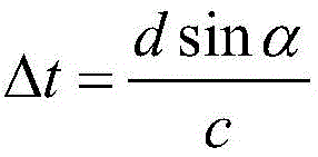
using formulas Determining the delay time delta t between two adjacent array elements; wherein d is the center distance between two adjacent array elements, alpha is the deflection angle of the acoustic beam, and c is the wave velocity of the ultrasonic wave in the medium;
using formulas Determining the delay time t of the ith array elementi(ii) a Wherein R is the vertical distance from the focal point to the plane of the array element group, and LiThe distance from the ith array element to the center of the array,
 n is the number of array elements in the array element group; t is t0Is a time constant, t0Greater than the minimum amount of delay in the focus delay.
Optionally, the controlling, by using an automatic tracking method, the moving device to track the workpiece to be detected according to the parameter of the workpiece to be detected, and detecting the workpiece to be detected specifically includes:
when the workpiece to be detected is a linear welding seam, a moving device is controlled to track the workpiece to be detected by adopting a method of adjacent point linear interpolation, and the workpiece to be detected is detected;
and when the workpiece to be detected is a nonlinear welding seam, controlling the mobile device to track the workpiece to be detected by adopting a pre-measurement tracking method, and detecting the workpiece to be detected.
Optionally, when the workpiece to be detected is a linear weld joint, the moving device is controlled to track the workpiece to be detected by using an adjacent point linear interpolation method, and the detecting of the workpiece to be detected specifically includes:
acquiring the contour of the linear welding seam;
and controlling the mobile device to track the contour of the linear welding seam by adopting a distance interpolation algorithm, and detecting the linear welding seam.
Optionally, when the workpiece to be detected is a nonlinear welding seam, the moving device is controlled to track the workpiece to be detected by using a pre-measurement tracking method, and the detection of the workpiece to be detected specifically includes:
acquiring the outline of the nonlinear weld joint; the non-linear contour comprises a plurality of contour points;
identifying inflection points of the contour of the nonlinear weld joint according to the contour;
determining a corresponding corner according to the inflection point; the corner is an area covered by the first five contour points and the last five contour points adjacent to the inflection point;
controlling a moving device to track the workpiece to be detected by adopting a method of adjacent point linear interpolation to the contour of a non-corner in the contour of the nonlinear welding seam, and detecting the workpiece to be detected;
and comparing the detection points with the point data at the corners of the contour of the nonlinear welding seam, updating the contour at the current corner, controlling a moving device at the current corner to track the workpiece to be detected according to the updated contour, and detecting the workpiece to be detected.
Optionally, the identifying an inflection point of the contour of the nonlinear weld according to the contour specifically includes:
obtaining any plurality of uniformly distributed contour points on a straight line part in the contour to form a reference straight line in a fitting manner;
sequentially acquiring the distance from each contour point behind the reference straight line to the reference straight line;
and when the distance from the ith contour point to the reference straight line is greater than a distance threshold value and the distance from the (i-1) th contour point to the reference straight line is less than or equal to the distance threshold value, determining the ith contour point as an inflection point corresponding to the reference straight line.
Optionally, the method includes, according to the parameter of the workpiece to be detected, controlling a moving device to track the workpiece to be detected by using an automatic tracking method, and detecting the workpiece to be detected, and then:
acquiring detection data of a phased array probe;
extracting feature information of defects in the detection data by adopting a deep learning model according to the detection data;
and determining the detection result of the workpiece to be detected according to the characteristic information of the defect.
According to the specific embodiment provided by the invention, the invention discloses the following technical effects:
the ultrasonic phased array detection device can meet the use requirements on different occasions in manufacturing and in service, breaks through the condition limitation that the field environment cannot work manually, greatly lightens the labor intensity of manual ultrasonic detection, and extends the working range. The automation of the whole set of intelligent detection equipment improves the detection efficiency and the accuracy of the detection result, and the detection operation can be flexibly carried out according to the environment. The detection device is provided with a high-precision encoder recording system, and can accurately position the position of the defect. The whole system improves the automation and intelligence level of ultrasonic phased array detection.
The invention adopts advanced phased array ultrasonic detection and automatic control technology, and the advantages of the two technologies complement each other. Compared with the traditional ultrasonic detection, the phased array ultrasonic detection has the functions of controlling the focusing and deflection of sound wave beams, realizes the full-coverage scanning of sound waves under the condition of not moving or slightly moving a probe, can probe workpieces with complex geometric shapes, and improves the detection speed; by optimizing the focusing rule and the probe, the detection resolution, the signal-to-noise ratio, the sensitivity and other properties can be greatly improved. The detection precision and reliability are improved, the evaluation on the welding seam is improved, and the problem that the detection is easy to miss when the traditional ultrasonic detection is used is avoided.
Drawings
In order to more clearly illustrate the embodiments of the present invention or the technical solutions in the prior art, the drawings needed to be used in the embodiments will be briefly described below, and it is obvious that the drawings in the following description are only some embodiments of the present invention, and it is obvious for those skilled in the art to obtain other drawings without inventive exercise.
FIG. 1 is a schematic structural diagram of an ultrasonic phased array inspection apparatus according to the present invention;
FIG. 2 is a schematic diagram illustrating the control of a mobile device in the ultrasonic phased array inspection apparatus according to the present invention;
FIG. 3 is a schematic diagram of the phased array acoustic wave deflection focusing of the present invention;
FIG. 4 is a schematic diagram of a phased array inspection process of the present invention;
FIG. 5 is a schematic flow chart of the tracking detection of the present invention;
FIG. 6 is a phased array ultrasonic testing control software interface of the present invention;
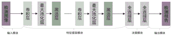
FIG. 7 is a schematic diagram of a deep learning convolutional neural network model according to the present invention;
FIG. 8 is a schematic flow chart of defect analysis using a deep learning model according to the present invention.
Detailed Description
The technical solutions in the embodiments of the present invention will be clearly and completely described below with reference to the drawings in the embodiments of the present invention, and it is obvious that the described embodiments are only a part of the embodiments of the present invention, and not all of the embodiments. All other embodiments, which can be derived by a person skilled in the art from the embodiments given herein without making any creative effort, shall fall within the protection scope of the present invention.
In order to make the aforementioned objects, features and advantages of the present invention comprehensible, embodiments accompanied with figures are described in further detail below.
Fig. 1 is a schematic structural diagram of an ultrasonic phased array detection apparatus of the present invention. As shown in fig. 1, the ultrasonic phased array inspection apparatus of the present invention includes: the device comprises a detection platform 1, a moving device 2, a clamping mechanism 3, a phased array probe 4, a vision sensor 5, a position encoder, a wedge block 6 and a controller. The detection platform 1 is arranged on the platform moving guide rail, the detection platform 1 is used for driving the welding line of the workpiece to be detected 7, 7-1, and 7-2 is the central line of the welding line. The stiff end of fixture 3 is fixed in on the mobile device 2, fixture 3's exposed core is used for the centre gripping phased array probe 4 with vision sensor 5. The position encoder is integrated on the wedge block 6 and used for recording the distance detected by the phased array probe 4, and the wedge block 6 and the phased array probe 4 are fixed into a whole. The output ends of the vision sensor 5, the position encoder and the phased array probe 4 are all connected with the controller, and the output end of the controller is connected with a driving motor of the mobile device 2. The controller is used for adjusting the moving parameters of the moving device 2 according to the parameters of the workpiece to be detected, the image acquired by the vision sensor 5 and the data acquired by the position encoder, and obtaining the detection result of the workpiece to be detected 7 according to the detection data of the phased array probe 4.
When the ultrasonic phased array detection device is used for detection, the phased array probe 4 is clamped by the clamping mechanism 3 at the tail end of the moving device 2, and a relative position encoder is adopted, so that a driving program in a controller is combined to drive a driving motor of the moving device 2, and an automatic control function is realized. The detection platform 1 moves on the guide rail, and the moving distance is accurately adjustable, so that the position of the carried workpiece to be detected is adjusted, and the workpiece to be detected is kept at an accurate distance from the relative position of the moving device 2.
The controller of the present invention employs a servo control strategy to control the movement parameters of the mobile device 2. Fig. 2 is a schematic control diagram of a mobile device in the ultrasonic phased array inspection apparatus according to the present invention. As shown in fig. 2, the basic principle of the servo control strategy is to calculate the pose information of the mobile device 2 after the image processing of the three-dimensional coordinate change of the probe in the working space by the vision sensor 5, and feed back the pose information to the mobile device controller. The self attitude and the motion parameters of the mobile device 2 are adjusted through the kinematics theory of the mobile device, and the attitude information is used as the input quantity of a joint controller to control the movement of the mobile device 2. The control strategy can complete the operation task accurately, flexibly and stably in real time. Specifically, the control accuracy of the mobile device 2 is improved by adopting a position-based visual servo method and a mounting mode of the visual sensor 5 for hand-eye synchronization. The position-based visual servo method can be accurate, specifically, the controller obtains three-dimensional coordinates of the intermediate point through characteristic points identified by the visual sensor 5 and by using a fixed distance interpolation algorithm, and the position and attitude information of the mobile device 2 at the corresponding position is obtained from the point coordinates through the kinematic principle of the mobile device 2. The image processing process and the motion control process of the mobile device 2 are processed separately in the controller, so that the complexity of the whole system is reduced. The hand-eye synchronization means that the position relationship between the visual sensor 5 and the clamping mechanism 3 at the tail end of the mobile device 2 is kept unchanged, the visual sensor 5 can move along with the tail end of the mobile device 2, the movement space is not limited, the system stability is good after the hand-eye calibration, and a complex work task can be completed.
As a specific embodiment, the relative position of the clamping end of the clamping mechanism 3 and the phased array probe 4 and the vision sensor 5 is fixed, and the fixed end of the clamping mechanism 3 is movably fixed on the moving device 2. The visual sensor 5 in the present invention may be a camera.
The invention also provides an ultrasonic phased array detection method, which adopts the ultrasonic phased array detection device shown in FIG. 1 to carry out detection and comprises the following specific steps:
step 100: and acquiring parameters of the workpiece to be detected. The parameters include shape, material, size and surface condition. The user needs to input parameters such as the shape, material, size, surface state and the like of the workpiece to be detected, and select a proper ultrasonic array transducer and wedge from the probe library.
Step 200: and determining the array element group corresponding to each detection angle and the delay time of each array element in the array element group according to the parameters of the workpiece to be detected. Fig. 3 is a schematic diagram of acoustic wave deflection focusing of the phased array, and a specific process of determining an array element group corresponding to a detection angle and a delay time of each array element in the array element group is specifically described with reference to fig. 3.
Calculating the deflection time delay of the phased array acoustic beam: the method can be deduced by a geometrical optics principle, and when the deflection angle of the sound beam is alpha, the excitation delay fixed difference delta t of adjacent array elements under the time sequence of the equal difference meets the following requirements:
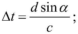
in the formula, d is the center distance between two adjacent array elements, alpha is the deflection angle of the sound beam, and c is the wave velocity of the ultrasonic wave in the medium.
Calculating the deflection focusing time delay of the phased array acoustic beam: as shown in FIG. 3, the focal point P, the focal length R, the deflection angle α, the delay time t of the ith array element is determined by the trigonometric cosine theoremi:
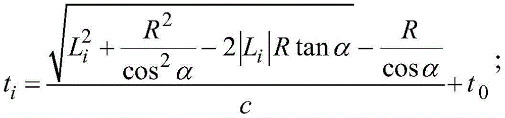
Wherein R is the vertical distance from the focal point P to the plane of the array element group, and LiThe distance from the ith array element to the center of the array, n is the number of array elements in the array element group; t is t0Is a time constant, t0Greater than the minimum delay in the focus delay, such that tiPositive values.
Fig. 4 is a schematic diagram of a phased array detection process of the present invention, and as shown in fig. 4, necessary parameters such as a detection distance, a deflection angle, a wedge position, and the like in a detection process can be automatically set, and data can be recorded.
Step 300: and controlling the moving device to track the workpiece to be detected by adopting an automatic tracking method according to the parameters of the workpiece to be detected, and detecting the workpiece to be detected.
FIG. 5 is a flow chart of the tracking detection according to the present invention. As shown in fig. 5, in a portion where the weld line contour is a straight line segment, the contour between the start points of the segment can be approximated to a straight line, and interpolation motion is performed by linear interpolation. In order to avoid the deformation distortion, the system at the corner of the welding seam outline compares the detection point with the corner data point on the welding seam central line in the model, and selects a part of the current corner data point in the model as the moving device to be controlled to move before the next detection cycle comes. The detection point of the invention is a point which is obtained by adding a compensation value to the characteristic point, wherein the position of the detection point meets the full coverage of the probe transmitting sound field to the welding seam, and the value is determined by the three-dimensional size of the welding seam and the coverage condition of the sound field. The detection process of the present invention is specifically described with reference to fig. 5.
For a linear welding seam, because any two adjacent detection points on the contour line are straight line segments, a linear interpolation method can be adopted to control the mobile device to track the contour line of the welding seam in real time. In order to ensure the motion stability of the mobile device and realize a better tracking effect, the number of interpolation points of each section of linear interpolation is changed correspondingly along with the increase of the tracking motion speed, specifically, a timing linear interpolation method can be adopted, the motion speed can be changed, and when the distance between two interpolation points is ensured to be less than or equal to 2mm, the interpolation time of the section corresponding to different speeds is calculated so as to ensure the track precision.
For non-linear welds, the present invention uses a model-based predictive mobile device weld tracking method due to the presence of one or more intermittent or continuous corners on the contour. The method has the basic principle that the contour line information in the three-dimensional model of the welding line is effectively utilized through pretreatment, different control strategies are adopted according to different contour segments, and good tracking accuracy is guaranteed when the speed is high. The specific implementation process is carried out according to the following steps:
1) and (6) performing weld seam outline pre-measurement. And matching the pre-measured value of the workpiece with the three-dimensional model imported in the system through the vision system. The method comprises the steps of firstly controlling a mobile device to move along the extending direction of a welding seam at a low speed, then enabling a camera fixed at the tail end of the mobile device to start capturing images, carrying out coordinate transformation on identified characteristic points (such as a starting point and an end point on an edge line between the welding seam and a parent metal) and transmitting space coordinate information to a mobile device controller. In addition, in order to obtain more welding seam contour points for obtaining more accurate contour information, the movement speed of the moving device is controlled in a lower range (1-3 mm/s). And finally, the spatial position of the weld contour line obtained by pre-measurement is stored in a data memory of the mobile device controller in the form of point data.
2) An inflection point identification method. In order to identify the location of the corner region, the inflection point needs to be identified quickly and efficiently. Firstly, randomly selecting five uniformly distributed points on a contour line and fitting the points into a straight line, and then sequentially calculating the distance from each other characteristic point to the fitted straight line. When the distance between a certain characteristic point and the fitted straight line is greater than a set threshold value, and the distance between the previous characteristic point adjacent to the certain characteristic point and the fitted straight line is less than or equal to the set threshold value, the point is identified as an inflection point, and the areas covered by the first five points and the last five points adjacent to the inflection point are regarded as corner areas.
3) And (5) real-time weld seam tracking. The mobile device will perform weld tracking movements based on the detection and judgment of the vision system. Each detection cycle identifies a feature point, which is also referred to as a detection point in the process. In the straight line section, a straight line interpolation method is adopted; in the part with the inflection point, the position of the corner area is firstly identified, the system compares the detection point with the corner data point on the central line of the welding line in the model, and selects a part of the data point at the current corner in the model as the moving device to be controlled to move before the next detection cycle comes.
FIG. 6 is a phased array ultrasonic inspection control software interface of the present invention. As shown in fig. 6, the software part of the present invention is an automated program integrating functions of detection focusing rule setting, motion control, data acquisition, real-time result analysis, etc. based on MFC programming. The control software may export a signal data file received from the probe into microsoft excel, MATLAB, or other external analysis program. The device can be used for quickly and accurately detecting workpieces with simple or complex shapes, and the flexibility and high-end function of the device can enable users to finish detection with strict detection standards and detection with continuously improved industrial requirements. On the premise of ensuring the detection quality, a plurality of probes are installed as far as possible in one detection process so as to reduce the labor intensity and shorten the working time.
When the ultrasonic signals are acquired, the data needs to be analyzed and processed. Improvements in current deep learning algorithms and computational tools (particularly GPU acceleration) enable more complex, more powerful models to achieve near human-level performance in image recognition and classification tasks. In actual detection, a manual inspector cannot describe the working experience accumulated for many years in an algorithm mode, and the characteristic information of the defect can be automatically extracted by building a deep learning model and used for automatically calculating and judging the size, the position and the type of the defect.
Fig. 7 is a schematic diagram of a deep learning convolutional neural network model of the present invention, and fig. 8 is a schematic diagram of a process of performing defect analysis by using the deep learning model of the present invention. As shown in FIGS. 7 and 8, the invention adopts a deep learning model to provide quality evaluation support for inspectors in the detection process and provide a defect detection report. And verifying the analysis result and the actual result, and establishing a database of the ultrasonic phased array detection of the workpiece, so that the reliability and the accuracy of the ultrasonic phased array detection are improved.
The following provides a detailed description of the embodiments of the invention.
The hardware part of the ultrasonic phased array detection device in the specific embodiment comprises a computer, an automatic moving device and a detection equipment system, and the software part comprises phased array ultrasonic detection control software. After the device is started, phased array control software is opened on a computer, a file corresponding to a workpiece to be detected is selected to be loaded, if the welding seam is detected, a three-dimensional model corresponding to the welding seam needs to be loaded, the file content comprises the number of probes, a scanning mode, a detection material, a sound wave mode, sound velocity, voltage, pulse repetition frequency, frequency bands, probe related information (such as type, frequency, total number of array elements, initial array elements, effective array element number, array element center distance and array element size), wedge related information (such as type, wedge sound velocity, wedge angle, center height and probe front distance) and the like. The system automatically calibrates the probe and wedge based on the loaded and entered information.
The control software judges whether the current space meets the requirement of detecting fan scanning or line scanning according to the distance and image information uploaded by the sensor in real time, controls the robot to adjust the distance between the probe and the central line of the welding seam through an automatic setting module in the control software after the scanning mode is determined, simulates and displays the covering condition of the deflected sound beam in the three-dimensional model of the workpiece in real time according to the change of the distance until the primary wave and the secondary wave meet the requirement of fully covering the welding seam, and automatically sets the focusing range and records the current position. The method comprises the steps that a corresponding test block is identified by a system through a machine vision method according to the material and size parameters of a workpiece, a probe is automatically moved and placed on the test block, the range and the gain are properly adjusted, then, a gate starting point or a gate width is automatically moved to select an echo corresponding to an aperture 1, the reflection time of the aperture 1 is obtained, then, the gate starting point or the gate width is moved to select an echo corresponding to an aperture 2, the reflection time of the aperture 2 is automatically obtained, and the system can automatically calculate the current sound velocity of the test block. The angle calibration and TCG preparation are completed according to the respective requirements of the angle calibration and TCG curve preparation. After the debugging of the phased array detection system is completed, the robot moves the probe to return to the previous recorded position, the system calculates a detection path according to the three-dimensional model of the workpiece, and the detection is automatically started and data is recorded in real time until all detection of the welding seam is completed.
The specific implementation can solve the problems of low automation degree, low detection efficiency, low reliability of detection results and the like in the conventional ultrasonic phased array industrial detection.
The embodiments in the present description are described in a progressive manner, each embodiment focuses on differences from other embodiments, and the same and similar parts among the embodiments are referred to each other.
The principles and embodiments of the present invention have been described herein using specific examples, which are provided only to help understand the method and the core concept of the present invention; meanwhile, for a person skilled in the art, according to the idea of the present invention, the specific embodiments and the application range may be changed. In view of the above, the present disclosure should not be construed as limiting the invention.
Claims (10)


Priority Applications (1)
| Application Number | Priority Date | Filing Date | Title |
|---|---|---|---|
| CN202010016927.XA CN113092588A (en) | 2020-01-08 | 2020-01-08 | Ultrasonic phased array detection device and detection method |
Applications Claiming Priority (1)
| Application Number | Priority Date | Filing Date | Title |
|---|---|---|---|
| CN202010016927.XA CN113092588A (en) | 2020-01-08 | 2020-01-08 | Ultrasonic phased array detection device and detection method |
Publications (1)
| Publication Number | Publication Date |
|---|---|
| CN113092588A true CN113092588A (en) | 2021-07-09 |
Family
ID=76663241
Family Applications (1)
| Application Number | Title | Priority Date | Filing Date |
|---|---|---|---|
| CN202010016927.XA Pending CN113092588A (en) | 2020-01-08 | 2020-01-08 | Ultrasonic phased array detection device and detection method |
Country Status (1)
| Country | Link |
|---|---|
| CN (1) | CN113092588A (en) |
Cited By (2)
| Publication number | Priority date | Publication date | Assignee | Title |
|---|---|---|---|---|
| CN114137085A (en) * | 2021-12-01 | 2022-03-04 | 仲恺农业工程学院 | Ultrasonic flaw detection robot based on vision-assisted positioning and detection method thereof |
| CN118731181A (en) * | 2024-09-03 | 2024-10-01 | 浙江理工大学 | Automated ultrasonic phased array detection device and detection method thereof |
Citations (8)
| Publication number | Priority date | Publication date | Assignee | Title |
|---|---|---|---|---|
| US6249718B1 (en) * | 1995-01-04 | 2001-06-19 | Malcolm T. Gilliland | Method for tracking joints and edges for welding operations |
| US20100106431A1 (en) * | 2008-10-29 | 2010-04-29 | Hitachi, Ltd. | Apparatus and method for ultrasonic testing |
| CN103753015A (en) * | 2013-12-27 | 2014-04-30 | 深圳市光大激光科技股份有限公司 | Welding seam tracking system and method of laser welding machine |
| CN106353410A (en) * | 2016-08-22 | 2017-01-25 | 南京越辰智能科技有限公司 | Ultrasonic phased array imaging detection device for aluminum alloy friction stir weldment |
| CN107424144A (en) * | 2017-04-26 | 2017-12-01 | 哈尔滨理工大学 | Weld joint tracking image processing algorithm based on laser vision |
| CN108169331A (en) * | 2017-12-04 | 2018-06-15 | 北京星航机电装备有限公司 | Thin plate lattice fin construction joint phased array ultrasonic detection device and detection method |
| US10324066B1 (en) * | 2015-12-31 | 2019-06-18 | VeriPhase, Inc. | System and method for the improved analysis of ultrasonic weld data |
| CN110530877A (en) * | 2019-09-16 | 2019-12-03 | 西安中科光电精密工程有限公司 | A kind of welding shape quality inspection robot and its detection method |
-
2020
- 2020-01-08 CN CN202010016927.XA patent/CN113092588A/en active Pending
Patent Citations (8)
| Publication number | Priority date | Publication date | Assignee | Title |
|---|---|---|---|---|
| US6249718B1 (en) * | 1995-01-04 | 2001-06-19 | Malcolm T. Gilliland | Method for tracking joints and edges for welding operations |
| US20100106431A1 (en) * | 2008-10-29 | 2010-04-29 | Hitachi, Ltd. | Apparatus and method for ultrasonic testing |
| CN103753015A (en) * | 2013-12-27 | 2014-04-30 | 深圳市光大激光科技股份有限公司 | Welding seam tracking system and method of laser welding machine |
| US10324066B1 (en) * | 2015-12-31 | 2019-06-18 | VeriPhase, Inc. | System and method for the improved analysis of ultrasonic weld data |
| CN106353410A (en) * | 2016-08-22 | 2017-01-25 | 南京越辰智能科技有限公司 | Ultrasonic phased array imaging detection device for aluminum alloy friction stir weldment |
| CN107424144A (en) * | 2017-04-26 | 2017-12-01 | 哈尔滨理工大学 | Weld joint tracking image processing algorithm based on laser vision |
| CN108169331A (en) * | 2017-12-04 | 2018-06-15 | 北京星航机电装备有限公司 | Thin plate lattice fin construction joint phased array ultrasonic detection device and detection method |
| CN110530877A (en) * | 2019-09-16 | 2019-12-03 | 西安中科光电精密工程有限公司 | A kind of welding shape quality inspection robot and its detection method |
Non-Patent Citations (2)
| Title |
|---|
| 王军: "超声相控线阵换能器的几何优化设计", 《工程科技Ⅱ辑》 * |
| 邓汛: "基于线结构光视觉的六轴机器人焊缝跟踪研究", 《信息科技辑》 * |
Cited By (3)
| Publication number | Priority date | Publication date | Assignee | Title |
|---|---|---|---|---|
| CN114137085A (en) * | 2021-12-01 | 2022-03-04 | 仲恺农业工程学院 | Ultrasonic flaw detection robot based on vision-assisted positioning and detection method thereof |
| CN118731181A (en) * | 2024-09-03 | 2024-10-01 | 浙江理工大学 | Automated ultrasonic phased array detection device and detection method thereof |
| CN118731181B (en) * | 2024-09-03 | 2024-12-13 | 浙江理工大学 | Automated ultrasonic phased array detection device and detection method thereof |
Similar Documents
| Publication | Publication Date | Title |
|---|---|---|
| CN109142533B (en) | A kind of rapid detection method and equipment for casting internal defects | |
| US8365602B2 (en) | Weld seam tracking system using phased array ultrasonic devices | |
| CN104985289B (en) | Laser sensor-based welding seam automatic tracking test device and test method thereof | |
| CN103969336B (en) | Automatic detecting and imaging method of hyper-acoustic phased array of weld joint in complex space | |
| CN103822970B (en) | A kind of portable resistor spot welding Automatic ultrasonic testing instrument and detection method | |
| CN102539532B (en) | An ultrasonic C-scan imaging method based on two-dimensional neighborhood synthetic aperture focusing | |
| CN211825860U (en) | Automatic flaw detection device guided by vision | |
| CN108318581B (en) | An automatic detection method of ultrasonic C-scanning of arc surface workpiece without clamping and positioning | |
| WO1992018862A1 (en) | Method and device for detecting flaw with ultrasonic wave | |
| CN114295728A (en) | Ultrasonic three-dimensional tomography method for internal defects of complex curved surface workpiece | |
| CA1270940A (en) | Method for classification of point and elongated single defects in workpieces by means of ultrasonics | |
| CN105699487A (en) | Manipulator detection device and method for residual stress of complex component | |
| CN107953336A (en) | Measured piece is loaded the modification method and system of deviation in manipulator Ultrasonic NDT | |
| CN114019024A (en) | A method and system for measuring the penetration depth of the lower layer of the weld in lap welding | |
| Xiao et al. | An optimized robotic scanning scheme for ultrasonic NDT of complex structures | |
| CN109342561A (en) | Ultrasonic testing device and method for curved surface weldment | |
| CN113075297A (en) | Titanium alloy phased array linear array ultrasonic detection sound field model construction method | |
| CN114674927B (en) | A method for detecting brazing defects by water immersion ultrasonic C with refracted waves perpendicular to the brazing surface | |
| CN113588798A (en) | Real-time automatic focusing method of ultrasonic scanning microscope | |
| CN113092588A (en) | Ultrasonic phased array detection device and detection method | |
| JP2016095238A (en) | Eddy current flaw detector and eddy current flaw detection method | |
| CN118893000B (en) | A control system for mobile phone frame BEND ultrasonic detection machine | |
| JPS63309852A (en) | Ultrasonic flaw detection equipment | |
| CN117871676B (en) | A non-scanning weld defect location method based on ultrasonic TOFD | |
| CN102749884A (en) | Light transmission scanning-detecting controlling method for ceramic antenna cover |
Legal Events
| Date | Code | Title | Description |
|---|---|---|---|
| PB01 | Publication | ||
| PB01 | Publication | ||
| SE01 | Entry into force of request for substantive examination | ||
| SE01 | Entry into force of request for substantive examination |