CN113081387A - Covered stent, covered stent conveying system and covered stent loading method - Google Patents
Covered stent, covered stent conveying system and covered stent loading method Download PDFInfo
- Publication number
- CN113081387A CN113081387A CN201911338818.3A CN201911338818A CN113081387A CN 113081387 A CN113081387 A CN 113081387A CN 201911338818 A CN201911338818 A CN 201911338818A CN 113081387 A CN113081387 A CN 113081387A
- Authority
- CN
- China
- Prior art keywords
- stent
- exposed
- graft
- support
- sheath
- Prior art date
- Legal status (The legal status is an assumption and is not a legal conclusion. Google has not performed a legal analysis and makes no representation as to the accuracy of the status listed.)
- Granted
Links
- 238000011068 loading method Methods 0.000 title claims description 21
- 238000004873 anchoring Methods 0.000 claims description 43
- 238000000034 method Methods 0.000 claims description 11
- 239000011248 coating agent Substances 0.000 claims description 9
- 238000000576 coating method Methods 0.000 claims description 9
- 210000002489 tectorial membrane Anatomy 0.000 claims description 4
- 230000000149 penetrating effect Effects 0.000 claims description 2
- 230000007423 decrease Effects 0.000 claims 2
- 239000012528 membrane Substances 0.000 abstract description 8
- 210000004204 blood vessel Anatomy 0.000 description 14
- 230000017531 blood circulation Effects 0.000 description 9
- 208000027418 Wounds and injury Diseases 0.000 description 7
- 238000002513 implantation Methods 0.000 description 7
- 230000006378 damage Effects 0.000 description 5
- 208000014674 injury Diseases 0.000 description 5
- 208000002251 Dissecting Aneurysm Diseases 0.000 description 4
- 210000002376 aorta thoracic Anatomy 0.000 description 4
- 206010002895 aortic dissection Diseases 0.000 description 4
- 230000000694 effects Effects 0.000 description 4
- 239000000463 material Substances 0.000 description 4
- 230000003213 activating effect Effects 0.000 description 3
- 239000008280 blood Substances 0.000 description 3
- 210000004369 blood Anatomy 0.000 description 3
- 208000037265 diseases, disorders, signs and symptoms Diseases 0.000 description 3
- 238000009958 sewing Methods 0.000 description 3
- 238000004804 winding Methods 0.000 description 3
- 208000007474 aortic aneurysm Diseases 0.000 description 2
- 230000006835 compression Effects 0.000 description 2
- 238000007906 compression Methods 0.000 description 2
- 238000005520 cutting process Methods 0.000 description 2
- 201000010099 disease Diseases 0.000 description 2
- 238000006073 displacement reaction Methods 0.000 description 2
- 229920000295 expanded polytetrafluoroethylene Polymers 0.000 description 2
- 210000003128 head Anatomy 0.000 description 2
- 210000003090 iliac artery Anatomy 0.000 description 2
- 238000011084 recovery Methods 0.000 description 2
- 238000001356 surgical procedure Methods 0.000 description 2
- 238000002560 therapeutic procedure Methods 0.000 description 2
- 230000008733 trauma Effects 0.000 description 2
- 238000003466 welding Methods 0.000 description 2
- 229920002799 BoPET Polymers 0.000 description 1
- 208000001750 Endoleak Diseases 0.000 description 1
- 229910000640 Fe alloy Inorganic materials 0.000 description 1
- 206010061218 Inflammation Diseases 0.000 description 1
- 208000034693 Laceration Diseases 0.000 description 1
- 239000004677 Nylon Substances 0.000 description 1
- 208000025865 Ulcer Diseases 0.000 description 1
- 210000000709 aorta Anatomy 0.000 description 1
- 210000000702 aorta abdominal Anatomy 0.000 description 1
- 239000002473 artificial blood Substances 0.000 description 1
- 230000004323 axial length Effects 0.000 description 1
- 239000000560 biocompatible material Substances 0.000 description 1
- 230000015572 biosynthetic process Effects 0.000 description 1
- 230000036772 blood pressure Effects 0.000 description 1
- 230000036770 blood supply Effects 0.000 description 1
- 230000004087 circulation Effects 0.000 description 1
- -1 cobalt-chromium-nickel-titanium-magnesium-iron Chemical compound 0.000 description 1
- 230000008602 contraction Effects 0.000 description 1
- 230000018109 developmental process Effects 0.000 description 1
- 238000010586 diagram Methods 0.000 description 1
- 238000002224 dissection Methods 0.000 description 1
- 238000005516 engineering process Methods 0.000 description 1
- 230000002349 favourable effect Effects 0.000 description 1
- 210000001105 femoral artery Anatomy 0.000 description 1
- 239000007943 implant Substances 0.000 description 1
- 230000004054 inflammatory process Effects 0.000 description 1
- 238000001746 injection moulding Methods 0.000 description 1
- 230000007794 irritation Effects 0.000 description 1
- 230000003902 lesion Effects 0.000 description 1
- 238000002844 melting Methods 0.000 description 1
- 239000002184 metal Substances 0.000 description 1
- 229910052751 metal Inorganic materials 0.000 description 1
- 239000007769 metal material Substances 0.000 description 1
- 229910001000 nickel titanium Inorganic materials 0.000 description 1
- HLXZNVUGXRDIFK-UHFFFAOYSA-N nickel titanium Chemical compound [Ti].[Ti].[Ti].[Ti].[Ti].[Ti].[Ti].[Ti].[Ti].[Ti].[Ti].[Ni].[Ni].[Ni].[Ni].[Ni].[Ni].[Ni].[Ni].[Ni].[Ni].[Ni].[Ni].[Ni].[Ni] HLXZNVUGXRDIFK-UHFFFAOYSA-N 0.000 description 1
- 229920001778 nylon Polymers 0.000 description 1
- 231100000915 pathological change Toxicity 0.000 description 1
- 230000036285 pathological change Effects 0.000 description 1
- 229920001343 polytetrafluoroethylene Polymers 0.000 description 1
- 239000004810 polytetrafluoroethylene Substances 0.000 description 1
- 230000002980 postoperative effect Effects 0.000 description 1
- 239000010935 stainless steel Substances 0.000 description 1
- 229910001220 stainless steel Inorganic materials 0.000 description 1
- 238000006467 substitution reaction Methods 0.000 description 1
- 231100000397 ulcer Toxicity 0.000 description 1
- 238000009941 weaving Methods 0.000 description 1
Images


Classifications
-
- A—HUMAN NECESSITIES
- A61—MEDICAL OR VETERINARY SCIENCE; HYGIENE
- A61F—FILTERS IMPLANTABLE INTO BLOOD VESSELS; PROSTHESES; DEVICES PROVIDING PATENCY TO, OR PREVENTING COLLAPSING OF, TUBULAR STRUCTURES OF THE BODY, e.g. STENTS; ORTHOPAEDIC, NURSING OR CONTRACEPTIVE DEVICES; FOMENTATION; TREATMENT OR PROTECTION OF EYES OR EARS; BANDAGES, DRESSINGS OR ABSORBENT PADS; FIRST-AID KITS
- A61F2/00—Filters implantable into blood vessels; Prostheses, i.e. artificial substitutes or replacements for parts of the body; Appliances for connecting them with the body; Devices providing patency to, or preventing collapsing of, tubular structures of the body, e.g. stents
- A61F2/02—Prostheses implantable into the body
- A61F2/04—Hollow or tubular parts of organs, e.g. bladders, tracheae, bronchi or bile ducts
- A61F2/06—Blood vessels
- A61F2/07—Stent-grafts
-
- A—HUMAN NECESSITIES
- A61—MEDICAL OR VETERINARY SCIENCE; HYGIENE
- A61F—FILTERS IMPLANTABLE INTO BLOOD VESSELS; PROSTHESES; DEVICES PROVIDING PATENCY TO, OR PREVENTING COLLAPSING OF, TUBULAR STRUCTURES OF THE BODY, e.g. STENTS; ORTHOPAEDIC, NURSING OR CONTRACEPTIVE DEVICES; FOMENTATION; TREATMENT OR PROTECTION OF EYES OR EARS; BANDAGES, DRESSINGS OR ABSORBENT PADS; FIRST-AID KITS
- A61F2/00—Filters implantable into blood vessels; Prostheses, i.e. artificial substitutes or replacements for parts of the body; Appliances for connecting them with the body; Devices providing patency to, or preventing collapsing of, tubular structures of the body, e.g. stents
- A61F2/95—Instruments specially adapted for placement or removal of stents or stent-grafts
- A61F2/962—Instruments specially adapted for placement or removal of stents or stent-grafts having an outer sleeve
- A61F2/966—Instruments specially adapted for placement or removal of stents or stent-grafts having an outer sleeve with relative longitudinal movement between outer sleeve and prosthesis, e.g. using a push rod
Landscapes
- Health & Medical Sciences (AREA)
- Engineering & Computer Science (AREA)
- Biomedical Technology (AREA)
- Heart & Thoracic Surgery (AREA)
- Public Health (AREA)
- Transplantation (AREA)
- Cardiology (AREA)
- Veterinary Medicine (AREA)
- Oral & Maxillofacial Surgery (AREA)
- Vascular Medicine (AREA)
- Life Sciences & Earth Sciences (AREA)
- Animal Behavior & Ethology (AREA)
- General Health & Medical Sciences (AREA)
- Gastroenterology & Hepatology (AREA)
- Pulmonology (AREA)
- Prostheses (AREA)
- Media Introduction/Drainage Providing Device (AREA)
Abstract
The invention discloses a covered membrane bracket which comprises a main body bracket and a skirt edge bracket, wherein the skirt edge bracket is sleeved on the outer surface of the main body bracket and is close to the near end of the main body bracket, the far end of the skirt edge bracket is connected with the outer surface of the main body bracket, the main body bracket comprises a plurality of first supporting bodies and first covered membranes connected with the plurality of first supporting bodies, the skirt edge bracket comprises a plurality of second supporting bodies and second covered membranes connected with the plurality of second supporting bodies, the first supporting bodies and the second supporting bodies both comprise a plurality of wave crests, the near end of the first supporting body closest to the near end of the main body bracket comprises a first exposed part, the near end of the second supporting body closest to the near end of the skirt edge bracket comprises a second exposed part, and the first exposed part and the second exposed part both comprise a plurality of exposed wave crests.
Description
Technical Field
The invention belongs to the field of medical instruments, and particularly relates to a covered stent, a covered stent conveying system and a covered stent loading method.
Background
This section provides background information related to the present disclosure only and is not necessarily prior art.
The aortic blood vessels of human body can cause damage to the intima or the vessel wall of the aortic blood vessels due to various pathological changes, such as inflammation, ulcer and the like, and aortic aneurysm or aortic dissection diseases are easily caused under the combined action of blood flow impact force. For diseases related to aortic dissection and the like, surgical treatment and interventional therapy are mainly used as treatment modes at present. The traditional surgical treatment is an operation, after blood circulation outside a built body is established, diseased blood vessels such as an aortic dissection are cut off, and then an artificial blood vessel is connected with the blood vessels to realize normal circulation of arterial blood. Because the traditional operation treatment has the problems of high risk, large trauma to people, long postoperative recovery time and the like, the interventional therapy method is more and more favored by doctors and patients.
With the continuous development of interventional technology, the advantages of adopting the covered stent to treat aortic aneurysm and arterial dissection diseases are prominent day by day. For the covered stent to be implanted into the thoracic aorta, the covered stent is used by the following steps: the stent is compressed into a sheath tube of a stent conveyor, a blood vessel is generally punctured at the position of a femoral artery or an iliac artery, a guide wire is utilized to establish a track, the conveyor establishes a conveying path through the iliac artery, an abdominal aorta, a thoracic aorta, an aortic arch and an ascending aorta, and after the conveying sheath tube with the pre-installed stent reaches a proper lesion position, the outer sheath tube is withdrawn through an external control mechanism, and the stent is released.
Particularly, when a chimney parallel stent treatment scheme is selected (namely, the branch stent is implanted outside the main stent and in parallel with the main stent), at least two stents are required to be implanted in the aortic arch part to isolate the lacerations, so that the aim of minimally invasive treatment is fulfilled. Therefore, at least two puncture holes need to be punctured on the body surface of a human body, the human body has large trauma and slow recovery, and meanwhile, the surgical complications are increased.
Disclosure of Invention
In view of the above problems, an object of the present invention is to at least solve the problem of the need to puncture a plurality of puncture holes on the body surface of a human body in a chimney parallel rack treatment scheme. The purpose is realized by the following technical scheme:
the utility model provides a tectorial membrane support, includes main part support and shirt rim support, the shirt rim support cup joints main part support's surface and being close to main part support's near-end, the distal end of shirt rim support with main part support's surface links to each other, main part support includes a plurality of first supporter and connects the first tectorial membrane of a plurality of first supporter, the shirt rim support includes a plurality of second supporters and connects the second tectorial membrane of a plurality of second supporters, first supporter with the second supporter all includes a plurality of crests, is the closest to main part support near-end the near-end of first supporter includes first exposed portion, is the closest to the shirt rim support near-end the near-end of second supporter includes the exposed portion of second, first exposed portion with the exposed portion of second all includes a plurality of exposed crests.
In one embodiment, the body stent includes a first stent section, a second stent section, and a connecting section connecting a distal end of the first stent section to a proximal end of the second stent section, the first stent section having an outer diameter smaller than an outer diameter of the second stent section, and the distal end of the skirt stent being connected to an outer surface of the first stent section.
In one embodiment, a proximal portion of the first cover covers a distal portion of the first support that is closest to the proximal end of the main stent.
In one embodiment, the first support and the second support each include a screw rod, and a diameter of the screw rod constituting the second support is at least smaller than a diameter of a portion of the screw rod constituting the first support.
A stent graft conveying system comprises a conveyor and any one of the stent grafts, wherein the conveyor is used for conveying the stent graft, the conveyor comprises a sheath core and an anchoring part, when the stent graft is loaded in the conveyor, the first exposed part is connected with the anchoring part, and the near end of the stent graft is closer to the near end of the conveyor than the far end of the stent graft.
In one embodiment, the anchoring portion includes a fixing member fixed to the sheath core and an anchoring member protruding from an outer surface of the fixing member, and a thickness of the anchoring member is gradually reduced from a proximal end to a distal end and/or a width of the anchoring member is gradually reduced from the proximal end to the distal end.
In one embodiment, the delivery device further comprises a bump structure disposed on the sheath core and protruding from the outer surface of the sheath core, the bump structure being closer to the distal end of the delivery device than the anchoring portion.
A loading method of a covered stent comprises the conveying system, the conveyor further comprises a sheath, and the sheath loading method comprises the following steps:
and sequentially penetrating a plurality of exposed wave crests on the first exposed part along the circumferential direction of the covered stent by using a pull wire, hanging the exposed wave crests on the first exposed part on the anchoring part, enabling the covered stent to move towards the near end of the conveyor, and taking the near end of the main stent into the conveyor.
In one embodiment, the loading method comprises the steps of:
and using a pull wire to penetrate through the second exposed part along the circumferential direction of the covered stent and move towards the proximal end of the conveyor, so that the proximal end of the skirt stent is retracted into the conveyor.
In one embodiment, when the first exposed portion and the second exposed portion are threaded with the pull wires, the first exposed portion and the second exposed portion are respectively threaded with the two pull wires.
In an embodiment, when the first exposed portion and the second exposed portion are threaded and wound by using a pull wire, the pull wire is simultaneously threaded and wound, and one end of the pull wire is firstly threaded and wound on a half circumference of the first exposed portion in the circumferential direction, then threaded to the second exposed portion, threaded and wound on the whole circumference along the circumferential direction of the second exposed portion, and then threaded to the other half circumference of the first exposed portion in the circumferential direction of the first exposed portion.
In one embodiment, the outer surface of the sheath core of the delivery device is provided with a bump structure, the bump structure is closer to the distal end of the delivery device than the anchoring part, and when the inner surface of the main body support is in contact with the bump structure, the pull wire is drawn out.
The invention has the advantages that:
the near ends of the main body support and the skirt edge support of the covered stent provided by the invention are respectively provided with the exposed part, so that reverse assembly can be realized during stent assembly, the exposed parts and the covered portion form small steps, the compressed section size of the exposed parts is smaller than that of the near end part of the covered stent, and the covered stent is more favorable for being assembled into a sheath. The delivery device of the covered stent delivery system provided by the invention is provided with an anchoring part at the proximal end of the sheath core, and the delivery device can load the stent on the delivery device in a reverse assembly mode. When the conveyor is used for implanting the chimney parallel support, the support on the conveyor is reversely assembled, so that the conveyor can convey the branch support to the position of the branch blood vessel through the puncture caused by implanting the main support, the injury of the puncture to a patient is reduced, and the influence of implantation of the branch blood vessel support on the safety and reliability of the aortic support can be reduced.
Drawings
The drawings are only for purposes of illustrating the preferred embodiments and are not to be construed as limiting the invention. Also, like reference numerals are used to refer to like parts throughout the drawings.
In the drawings:
FIG. 1 is a schematic diagram of a conveyor according to an embodiment of the invention;
FIG. 2 is a schematic view of an anchor portion according to an embodiment of the present invention;
FIG. 3 is a schematic view of another anchor portion of an embodiment of the present invention;
FIG. 4 is a schematic view of a bracket according to an embodiment of the invention;
FIGS. 5a to 5c are schematic views illustrating a stent assembling process in the stent delivery system according to an embodiment of the present invention;
FIG. 6 is a schematic view of a stent delivery system according to an embodiment of the present invention in use in a chimney parallel stent treatment protocol;
fig. 7 is a schematic view of the stent in the configuration of fig. 6 after deployment.
Detailed Description
Exemplary embodiments of the present disclosure will be described in more detail below with reference to the accompanying drawings. While exemplary embodiments of the present disclosure are shown in the drawings, it should be understood that the present disclosure may be embodied in various forms and should not be limited to the embodiments set forth herein. Rather, these embodiments are provided so that this disclosure will be thorough and complete, and will fully convey the scope of the disclosure to those skilled in the art.
It is to be understood that the terminology used herein is for the purpose of describing particular example embodiments only, and is not intended to be limiting. As used herein, the singular forms "a", "an" and "the" may be intended to include the plural forms as well, unless the context clearly indicates otherwise. The terms "comprises," "comprising," "including," and "having" are inclusive and therefore specify the presence of stated features, steps, operations, elements, and/or components, but do not preclude the presence or addition of one or more other features, steps, operations, elements, components, and/or groups thereof. The method steps, processes, and operations described herein are not to be construed as necessarily requiring their performance in the particular order described or illustrated, unless specifically identified as an order of performance. It should also be understood that additional or alternative steps may be used.
Although the terms first, second, third, etc. may be used herein to describe various elements, components, regions, layers and/or sections, these elements, components, regions, layers and/or sections should not be limited by these terms. These terms may be only used to distinguish one element, component, region, layer or section from another region, layer or section. Terms such as "first," "second," and other numerical terms when used herein do not imply a sequence or order unless clearly indicated by the context. Thus, a first element, component, region, layer or section discussed below could be termed a second element, component, region, layer or section without departing from the teachings of the example embodiments.
For convenience of description, spatially relative terms, such as "inner", "outer", "lower", "below", "upper", "above", and the like, may be used herein to describe one element or feature's relationship to another element or feature as illustrated in the figures. Such spatially relative terms are intended to encompass different orientations of the device in use or operation in addition to the orientation depicted in the figures. For example, if the device in the figures is turned over, elements described as "below" or "beneath" other elements or features would then be oriented "above" or "over" the other elements or features. Thus, the example term "below … …" can include both an orientation of above and below. The device may be otherwise oriented (rotated 90 degrees or at other orientations) and the spatially relative descriptors used herein interpreted accordingly.
In addition, when describing the implant, the orientation may be defined according to the blood flow direction, and the blood flow is defined to flow from the proximal end to the distal end, for example, for a stent, the end where the blood flows in is defined as the "proximal end" and the end where the blood flows out is defined as the "distal end"; for devices that require direct operator action, such as conveyors, the present invention defines the end closer to the operator as the "proximal end" and the end further from the operator as the "distal end".
As shown in FIG. 1, an embodiment of the first aspect of the present invention provides a transporter 100 for loading and transporting a stent graft 200. Specifically, the transporter 100 includes a sheath 10, a sheath core 20 axially movably disposed through the sheath 10, and an anchoring portion 40 disposed at a distal end portion of the sheath core 20.
In some embodiments of the present invention, the anchoring portion 40 includes a fixing member 41 and an anchoring member 42, the fixing member 41 is fixed to the sheath core 20, the anchoring member 42 protrudes from the outer surface of the fixing member 41, and the anchoring member 42 is used for anchoring the proximal end of the stent 200.
The fixing member 41 may be a hollow ring structure, which may be fixed to the sheath core 20 by means of bonding, welding, or injection molding.
In a specific embodiment, as shown in fig. 2, the anchoring element 42 is a wedge-shaped structure having a proximal thickness greater than a distal thickness, wherein the thickness of the anchoring element 42 refers to the dimension of the anchoring element 42 in the radial direction of the sheath core 20. In this embodiment, the formation of the sloped region between the proximal and distal ends of the anchor 42 reduces the overall volume of the anchor 42, making it easier for the covered portion of the stent 200 to enter the sheath 10. In addition, when the covered stent is loaded, the exposed wave crest is hooked at the near end of the anchoring piece, the supporting body close to the wave crest on the covered stent and the covering film can be accumulated at the far end of the anchoring piece when being compressed, and the thickness of the far end of the anchoring piece is small, so that the size of the covered stent after being compressed can be reduced on the whole, and the size of the outer sheath tube can be reduced to a certain extent. Moreover, the distal end of the anchoring element is thin and flat, and will not resist the compression of the stent and burst the covering membrane.
In another specific embodiment, as shown in fig. 3, the anchoring elements 42 have a triangular structure, wherein the proximal ends of the anchoring elements 42 have a larger circumferential dimension than the distal ends, i.e., the proximal ends of the anchoring elements 42 are the bottom edges of the triangular structure, and the distal ends of the anchoring elements 42 have the top angles β of the triangular structure, so that the overall volume of the anchoring elements 42 can be reduced, and the covered portion of the stent 200 can enter the sheath 10 more easily. Preferably, the apex angle β may range from 30 ≦ β ≦ 60. It will be appreciated that in other embodiments, both the thickness and the width of the anchor may taper from the proximal end to the distal end.
The number of anchors 42 can be between 1 and 5 on the same circumference of the fixture 41.
In some embodiments of the invention, the delivery device 100 further comprises a bump structure 50 disposed on the sheath core 20 and protruding from the outer surface of the sheath core 20, the bump structure 50 being closer to the proximal end of the delivery device than the anchor. When the stent 200 is contracted to a certain extent, the bump structures 50 can be brought into contact with the inner wall of the stent 200, thereby increasing the frictional force between the stent 200 and the sheath core 20, and in addition, the stent 200 can be prevented from being shortened when the stent 200 is released.
In some embodiments of the present invention, the delivery device 100 further comprises a pusher 60 coupled to the proximal end of the sheath core 20, and the proximal end of the stent 200 can be abutted by the distal end of the pusher 60, so that the stent 200 is not moved proximally when being received in the sheath 10 or when releasing the stent 200 from the sheath 10.
In some embodiments of the invention, the delivery device 100 further comprises a guide tip 70 attached to the distal end of the sheath core 20, the guide tip 70 being used to guide the delivery device 100 along the guidewire 300 into the blood vessel. In order to reduce the scratch of the guiding head 70 on the blood vessel, the guiding head 70 can be arranged in a conical shape.
In some embodiments of the present invention, when loading the stent, the guiding sheath 80 is further used in combination, the guiding sheath 80 is sleeved on the distal end of the sheath tube 10, and both ends of the guiding sheath 80 are in a gradually expanding trumpet-shaped structure. During loading of the stent 200 into the transporter 100, the proximal opening of the stent 200 may be compressed once by the introducer sheath 80 before entering the sheath 10, and then further contracted by the pull wire 30 before entering the sheath 10.
In some embodiments of the present invention, the pull wire 30 may be suture or nylon thread commonly used in medical devices, which has a certain strength and does not damage the supporting structure and the covering structure of the stent 200. In other embodiments, the pulling wire 30 may also be a material with a certain rigidity to ensure that the pulling wire 30 does not detach or break from the sheath tube 10 and the sheath core 20. As long as it is difficult to guarantee the stayguy to split or the stayguy material is difficult to drop. Further, the wire diameter of the pulling wire 30 may be between 0.07mm and 0.1 mm.
Embodiments of the second aspect of the present invention provide a stent graft delivery system that includes a stent graft 200 and the conveyor 100 of any of the above embodiments.
According to the stent graft conveying system of the embodiment of the invention, the conveyor 100 of the embodiment of the first aspect of the invention is provided, so that the stent graft conveying system of the embodiment of the invention has all the technical effects of the conveyor 100.
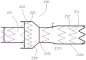
Specifically, as shown in FIG. 4, the stent graft 200 includes a body stent 210 and a skirt stent 220, the skirt stent 220 being sleeved on the outer surface of the body stent 210 near the proximal end of the body stent. The distal end of skirt hanger 220 is attached to the outer surface of body hanger 210, i.e., skirt hanger 220 has a proximally facing opening. The main body support 210 includes a plurality of first supports 211 and a first cover 212 connecting the plurality of first supports 211. The skirt hanger 220 includes a plurality of second supports 221 and a second cover 222 connecting the plurality of second supports 221. The proximal end of the body bracket 210 forms a first proximal opening and the distal end of the body bracket 210 forms a first distal opening. The proximal end of skirt hanger 220 is formed with a second proximal opening. The proximal end of a first support 211 closest to the proximal end of the body frame 210 has a first exposed portion not covered by the first cover 212, and the proximal end of a second support 221 closest to the proximal end of the skirt frame 220 has a second exposed portion not covered by the second cover 222.
In the present embodiment, the stent graft 200 is a double-layered stent comprising a main stent 210 and a skirt stent 220, wherein the main stent 210 has a large radial force and can resist the contraction of the blood vessel and keep the blood flow smooth, and when the stent graft 200 is used for branch blood supply, the skirt stent 220 can be squeezed and deformed to eliminate the implanted aortic stent and the gap between the main stent and the blood vessel wall. In addition, a first exposed part and a second exposed part are respectively formed at the first proximal opening and the second proximal opening, one purpose is to facilitate the threading and winding of the pull wire 30, the second purpose is to form a small step with the initial position of the covering film, so that the covering film part can be more easily contracted and enter the sheath tube 10, the third purpose is to easily expand and unfold by self when the covered stent 200 is released, and the constraint between the covering film on the skirt stent and the covering film on the main stent is reduced.
The first supporting body 211 and the second supporting body 221 both comprise a plurality of wave rings arranged along the length direction of the stent, the wave ring structure is W-shaped, and the wave ring structure has a plurality of turning vertexes. Accordingly, the first exposed portion is a portion of one wave ring at the nearest end on the first supporting body 211, the second exposed portion is a portion of one wave ring at the nearest end on the second supporting body 221, and both the first exposed portion and the second exposed portion include a plurality of exposed wave peaks. That is, the coating only covers a part of one wave circle at the nearest end, so that the wave crest is exposed. Thus, a small step is formed between the exposed peak and the proximal end of the cover.
In addition, the outer diameter of the first stent section of the present invention is smaller than that of the second stent section, and when the supporters of the first and second stent sections have the same number of peaks and valleys and the wire diameters of the lead screws constituting the supporters are the same, the radial deformability of the first stent section is greater than that of the second stent section. When the stent graft of the invention is implanted close to the aortic stent, the proximal opening of the first stent section is not excessively pressed by the aortic stent, thereby influencing the blood inflow branch. It can be understood that when the radial deformability of the first stent section is large, the difficulty of loading the stent is increased, so that the first exposed part is arranged at the proximal end part of the first stent section, so that a small step is formed between the exposed part and the proximal end of the covering membrane, when the covered stent is loaded into the sheath, the exposed part with the smaller compressed section size enters the sheath firstly, and then the part, which is slightly larger than the exposed part and is provided with the covering membrane, enters the sheath, so that the loading difficulty of the covered stent is reduced.
When the covered stent is compressed and transferred, the skirt stent and the main stent have a partial overlapping area, and if the diameter of the screw rod forming the first support body is the same as that of the screw rod forming the second support body, the cross-sectional dimension of the overlapping area is larger than that of the rest of the covered stent after the covered stent is compressed. To reduce the effect of this overlap region on the overall delivered size of the stent graft, in other embodiments, the wire diameter of the struts in this region may be suitably reduced such that the compressed cross-sectional dimension of the overlap region is at least no greater than the compressed cross-sectional dimension of the second stent segment. That is, the diameter of the lead screw constituting the second support body in the skirt hanger is at least smaller than the diameter of a part of the lead screw of the first support body, and more preferably, the diameter of the lead screw of the first support body in the region of the main body hanger overlapping with the skirt hanger is smaller than the diameter of the lead screw of the first support body in the remaining part of the main body hanger.
In some embodiments of the present invention, the distal end of the first coating 212 matches the shape of the distal end of the main stent 210, that is, the wave rod of the most distal wave ring of the first support 211 is completely covered by the first coating 212, but there is no coating between two adjacent wave troughs, so that the friction force with the delivery device during stent assembly can be increased, and the irritation to the vessel wall can be reduced.
The skirt hanger 220 and the body hanger 210 can be connected by sewing or welding.
To ensure that the stent graft 200 will not obstruct blood flow from the end of the implanted aortic stent after implantation, the distance between the proximal end of the skirt stent 220 and the proximal end of the body stent 210 is preferably 10mm to 15 mm.
Both the first support 211 and the second support 221 may be made of various biocompatible materials, including materials known in implantable medical devices or combinations of materials, such as 316L stainless steel, cobalt-chromium-nickel-titanium-magnesium-iron alloy, nitinol, and the like, or other biocompatible metallic materials. The first support 211 and the second support 221 may be formed by winding or cutting metal wires, or the connection between the support structures may be achieved by sewing, winding, weaving, cutting, or coating. The first and second cover films 212 and 222 may be ePTFE films or PET films, and may cover the first and second supports 211 and 221 by sewing or heat-melting, etc.
When a stent having a multi-layered structure similar to the stent graft 200 of the present invention is double-layered PTFE or ePTFE membrane, the membrane tends to adhere between the layers, which can interfere with the expansion of the stent after compression. In the present invention, the proximal end of the skirt stent 220 is configured as a half-bare structure (i.e., a second bare portion is formed), and since the half-bare wave ring is not adhered to the first coating of the main stent 210, when the stent graft 200 is expanded, the proximal edge expands and expands itself, thereby driving other coating portions to expand, and preventing the outer skirt stent 220 from failing to expand.
In some embodiments of the present invention, the pull wire 30 includes a first pull wire 301 for circumferentially wrapping around the first exposed portion and a second pull wire 302 for circumferentially wrapping around the second exposed portion when the stent is loaded. In yet other embodiments, the pull wire 30 may be only one, and the pull wire may be threaded through both the first exposed portion and the second exposed portion, and the first proximal opening and the second proximal opening may be contracted simultaneously when the pull wire is moved in the proximal direction.
Embodiments of the third aspect of the present invention provide a loading method of a lumen stent, which is implemented based on the stent delivery system in any one of the above embodiments. As shown in fig. 5a to 5c, specifically, the loading method includes:
s101: sheathing the guide sheath 80 at the distal end of the sheath tube 10, and sheathing the covered stent 200 on the sheath core 20;
s102: after the pull wire 30 is threaded around the first exposed part of the covered stent 200, the free end of the pull wire 30 is threaded out from the proximal end of the sheath tube 10;
s103: hanging the first exposed portion on the protruding portion 42 of the anchoring portion 40, activating the pull wire 30 to contract the first proximal opening of the stent graft 200;
s104: controlling the sheath 10 to move towards the distal end of the conveyor, and pulling the pull wire 30 to gradually accommodate the proximal end of the main body bracket 210 in the sheath 10;
s105: after the pull wire 30 is threaded around the second exposed part of the covered stent 200, the free end of the pull wire 30 is threaded out from the proximal end of the sheath tube 10;
s106: activating the pull wire 30 to contract the second proximal opening of the stent graft 200;
s107: controlling the sheath 10 to move towards the far end of the conveyor, and pulling the pull wire 30 to gradually accommodate the near end of the skirt stent 220 in the sheath 10;
s108: the sheath 10 continues to be controlled to move toward the distal end of the transporter until the stent graft 200 is fully received within the sheath 10.
Before the proximal end of the main stent 210 is pulled into the sheath 10, the stent graft 200 is anchored by hooking the first exposed portion on the protrusion 42 of the anchoring portion 40. After the covered portion of the stent graft 200 contacts a portion of the bump structure 50, the puller wire 30 is withdrawn in order to anchor the proximal portion of the main stent graft 210, without affecting subsequent assembly after withdrawal of the puller wire 30. When the pull wire passes through the sheath, the pull wire can conveniently pass through the sheath due to certain hardness, and other tools can be used, so that the invention is not described in detail.
In addition, after the proximal end of the skirt stent 220 is pulled into the sheath 10, when the skirt stent 220 completely enters the sheath 10, the pull wire 30 is pulled out, and subsequent assembly is not affected after the pull wire 30 is pulled out.
In some other embodiments, steps S102 to S108 may be replaced with:
s102': after the pull wire 30 is threaded around the first exposed part and the second exposed part of the covered stent 200, the free end of the pull wire 30 is threaded out from the proximal end of the sheath tube 10;
s103': activating the pull wire 30 to contract the first proximal opening and the second proximal opening of the stent graft 200;
s104', the sheath 10 is controlled to move towards the distal end of the conveyer, and the pull wire 30 is pulled, so that the covered stent 200 is gradually accommodated in the sheath from the proximal end to the distal end.
In this embodiment, the half-turn of the first exposed portion may be sequentially threaded by the pull wire 30, one free end of the pull wire 30 led out may be threaded through the second exposed portion counterclockwise, the free end is pulled back to the first exposed portion to continue to thread around the remaining half-turn, and then the free end is led out from the proximal end of the sheath 10. The first proximal opening and the second proximal opening of the stent graft 200 may be contracted simultaneously by pulling the pull wire 30 in this embodiment.
According to the loading method provided by the invention, the pull wire is used for binding and tightening the proximal end of the covered stent, and the covered stent can be quickly loaded into the sheath even if the radial supporting force of the proximal end of the covered stent is large. In addition, when the guiding sheath is matched for use, the guiding sheath can also play a role in pre-compressing and dispersing the stress of the sheath tube to a certain extent.
After loading according to the loading method of the present invention, the proximal end of the stent graft is adjacent the proximal end of the conveyor and the distal end of the stent graft is adjacent the distal end of the conveyor. So that the stent graft can be implanted reversely when released from the delivery device and implanted into the human body.
The effects of the present invention will be described below with reference to specific examples:
as shown in fig. 6, the chimney parallel stent implantation procedure for the delivery device is set forth below:
As shown in FIG. 7, the stent graft 200 is released from the first distal opening, anchored with the branch vessel 802 first, and then released to the first proximal opening of the stent graft 200. As shown in FIG. 7, the gap formed by the stent graft 200 and the large stent 803 being squeezed is blocked by the skirt stent 220, effectively preventing endoleaks.
The above description is only for the preferred embodiment of the present invention, but the scope of the present invention is not limited thereto, and any changes or substitutions that can be easily conceived by those skilled in the art within the technical scope of the present invention are included in the scope of the present invention. Therefore, the protection scope of the present invention shall be subject to the protection scope of the appended claims.
Claims (12)
1. A tectorial membrane stent comprises a main body stent and a skirt stent, wherein the skirt stent is sleeved on the outer surface of the main body stent and is close to the near end of the main body stent, the far end of the skirt edge support is connected with the outer surface of the main body support, the main body support comprises a plurality of first supporting bodies and a first coating connected with the plurality of first supporting bodies, the skirt stent comprises a plurality of second supporting bodies and a second coating film connected with the plurality of second supporting bodies, the first supporting bodies and the second supporting bodies both comprise a plurality of wave crests, the near-end of the first support body closest to the near-end of the main body support comprises a first exposed portion, the near-end of the second support body closest to the near-end of the skirt edge support comprises a second exposed portion, and the first exposed portion and the second exposed portion both comprise a plurality of exposed wave crests.
2. The stent graft of claim 1, wherein the body stent comprises a first stent section, a second stent section, and a connecting section connecting a distal end of the first stent section to a proximal end of the second stent section, wherein the first stent section has an outer diameter smaller than the outer diameter of the second stent section, and wherein the distal end of the skirt stent is attached to the outer surface of the first stent section.
3. The stent-graft of claim 1, wherein a proximal portion of the first stent-graft covers a distal portion of the first support that is closest to the proximal end of the main stent-graft.
4. The stent graft as recited in claim 1, wherein the first support and the second support each comprise a lead screw, the lead screw comprising the second support having a wire diameter at least smaller than a wire diameter of a portion of the lead screw comprising the first support.
5. A stent graft delivery system, comprising a delivery device for delivering the stent graft and the stent graft of any one of claims 1-4, the delivery device comprising a sheath core and an anchoring portion, the first exposed portion being coupled to the anchoring portion when the stent graft is loaded in the delivery device, and the proximal end of the stent graft being closer to the proximal end of the delivery device than the distal end of the stent graft.
6. The stent graft delivery system of claim 5, wherein the anchoring portion includes a fixing element fixed to the sheath core and an anchoring element protruding from an outer surface of the fixing element, and wherein the anchoring element has a thickness that decreases gradually from a proximal end to a distal end and/or a width that decreases gradually from a proximal end to a distal end.
7. The stent graft delivery system of claim 6, wherein the delivery device further comprises a bump structure disposed on the sheath core and protruding from an outer surface of the sheath core, the bump structure being closer to the distal end of the delivery device than the anchoring portion.
8. A method of loading a stent graft, comprising the delivery system of claim 5, the transporter further comprising a sheath, the method of loading the sheath comprising the steps of:
and sequentially penetrating a plurality of exposed wave crests on the first exposed part along the circumferential direction of the covered stent by using a pull wire, hanging the exposed wave crests on the first exposed part on the anchoring part, enabling the covered stent to move towards the near end of the conveyor, and taking the near end of the main stent into the conveyor.
9. The method of loading a stent graft of claim 8, comprising the steps of:
and using a pull wire to penetrate through the second exposed part along the circumferential direction of the covered stent and move towards the proximal end of the conveyor, so that the proximal end of the skirt stent is retracted into the conveyor.
10. The method of loading a stent graft of claim 9, wherein the first exposed portion and the second exposed portion are threaded using two pull wires, one each.
11. The method of loading a stent graft of claim 9, wherein the first and second exposed portions are threaded with a pull wire, wherein the pull wire is threaded with a pull wire, and wherein one end of the pull wire is threaded circumferentially around one half of the first exposed portion, then threaded to the second exposed portion, threaded circumferentially around the second exposed portion for the entire circumference, and then threaded to the first exposed portion for the other half of the first exposed portion.
12. The method of claim 8, wherein the outer surface of the sheath core of the delivery device is provided with a bump structure, the bump structure is closer to the distal end of the delivery device than the anchoring portion, and the pull wire is withdrawn when the inner surface of the main stent body is in contact with the bump structure.
Priority Applications (1)
| Application Number | Priority Date | Filing Date | Title |
|---|---|---|---|
| CN201911338818.3A CN113081387B (en) | 2019-12-23 | 2019-12-23 | Covered stent, covered stent conveying system and covered stent loading method |
Applications Claiming Priority (1)
| Application Number | Priority Date | Filing Date | Title |
|---|---|---|---|
| CN201911338818.3A CN113081387B (en) | 2019-12-23 | 2019-12-23 | Covered stent, covered stent conveying system and covered stent loading method |
Publications (2)
| Publication Number | Publication Date |
|---|---|
| CN113081387A true CN113081387A (en) | 2021-07-09 |
| CN113081387B CN113081387B (en) | 2023-12-05 |
Family
ID=76663009
Family Applications (1)
| Application Number | Title | Priority Date | Filing Date |
|---|---|---|---|
| CN201911338818.3A Active CN113081387B (en) | 2019-12-23 | 2019-12-23 | Covered stent, covered stent conveying system and covered stent loading method |
Country Status (1)
| Country | Link |
|---|---|
| CN (1) | CN113081387B (en) |
Cited By (1)
| Publication number | Priority date | Publication date | Assignee | Title |
|---|---|---|---|---|
| WO2024139844A1 (en) * | 2022-12-30 | 2024-07-04 | 先健科技(深圳)有限公司 | Double-layer lumen stent |
Citations (19)
| Publication number | Priority date | Publication date | Assignee | Title |
|---|---|---|---|---|
| US20050049674A1 (en) * | 2003-09-03 | 2005-03-03 | Berra Humberto A. | Stent graft |
| US20070250069A1 (en) * | 2006-04-19 | 2007-10-25 | Cook Incorporated | Delivery device for an endoluminal prosthesis |
| US20080262592A1 (en) * | 2007-04-23 | 2008-10-23 | Boston Scientific Scimed, Inc. | Intraluminary stent relocating apparatus |
| CN201445575U (en) * | 2009-04-29 | 2010-05-05 | 天健医疗科技(苏州)有限公司 | Artery tectorial membrane support and conveyer thereof |
| US20110125244A1 (en) * | 2009-11-18 | 2011-05-26 | Roeder Blayne A | Stent graft and introducer assembly |
| CN102462565A (en) * | 2011-10-25 | 2012-05-23 | 张石江 | Recoverable adjustable interventional stent for constriction in blood vessel |
| CN104644293A (en) * | 2014-12-30 | 2015-05-27 | 上海百心安生物技术有限公司 | Pressing and holding method and pressing and holding structure of intravascular stent |
| CN105496603A (en) * | 2015-12-30 | 2016-04-20 | 先健科技(深圳)有限公司 | Pipe cavity bracket |
| CN205494093U (en) * | 2015-12-30 | 2016-08-24 | 先健科技(深圳)有限公司 | Tubular cavity stent |
| US20160270935A1 (en) * | 2015-03-16 | 2016-09-22 | Cook Medical Technologies Llc | System and method for the sequential expansion of a medical device |
| WO2016173553A1 (en) * | 2015-04-30 | 2016-11-03 | 微创心脉医疗科技(上海)有限公司 | Support and drug delivery device |
| CN106687074A (en) * | 2014-09-23 | 2017-05-17 | 波顿医疗公司 | Vascular repair device and method of use |
| CN108261252A (en) * | 2016-12-30 | 2018-07-10 | 先健科技(深圳)有限公司 | Intraluminal stent and transport system |
| CN109091274A (en) * | 2018-09-04 | 2018-12-28 | 浦易(上海)生物技术有限公司 | A method of bracket is held for pressing |
| CN109152638A (en) * | 2016-04-12 | 2019-01-04 | 美敦力瓦斯科尔勒公司 | trench fill stent graft and method |
| CN109464212A (en) * | 2018-12-14 | 2019-03-15 | 东莞先健畅通医疗有限公司 | Overlay film frame |
| CN109498211A (en) * | 2018-11-27 | 2019-03-22 | 东莞先健畅通医疗有限公司 | Intraluminal stent |
| CN109700570A (en) * | 2018-12-28 | 2019-05-03 | 东莞先健畅通医疗有限公司 | Overlay film frame |
| CN109700568A (en) * | 2018-12-28 | 2019-05-03 | 东莞先健畅通医疗有限公司 | Overlay film frame |
-
2019
- 2019-12-23 CN CN201911338818.3A patent/CN113081387B/en active Active
Patent Citations (19)
| Publication number | Priority date | Publication date | Assignee | Title |
|---|---|---|---|---|
| US20050049674A1 (en) * | 2003-09-03 | 2005-03-03 | Berra Humberto A. | Stent graft |
| US20070250069A1 (en) * | 2006-04-19 | 2007-10-25 | Cook Incorporated | Delivery device for an endoluminal prosthesis |
| US20080262592A1 (en) * | 2007-04-23 | 2008-10-23 | Boston Scientific Scimed, Inc. | Intraluminary stent relocating apparatus |
| CN201445575U (en) * | 2009-04-29 | 2010-05-05 | 天健医疗科技(苏州)有限公司 | Artery tectorial membrane support and conveyer thereof |
| US20110125244A1 (en) * | 2009-11-18 | 2011-05-26 | Roeder Blayne A | Stent graft and introducer assembly |
| CN102462565A (en) * | 2011-10-25 | 2012-05-23 | 张石江 | Recoverable adjustable interventional stent for constriction in blood vessel |
| CN106687074A (en) * | 2014-09-23 | 2017-05-17 | 波顿医疗公司 | Vascular repair device and method of use |
| CN104644293A (en) * | 2014-12-30 | 2015-05-27 | 上海百心安生物技术有限公司 | Pressing and holding method and pressing and holding structure of intravascular stent |
| US20160270935A1 (en) * | 2015-03-16 | 2016-09-22 | Cook Medical Technologies Llc | System and method for the sequential expansion of a medical device |
| WO2016173553A1 (en) * | 2015-04-30 | 2016-11-03 | 微创心脉医疗科技(上海)有限公司 | Support and drug delivery device |
| CN205494093U (en) * | 2015-12-30 | 2016-08-24 | 先健科技(深圳)有限公司 | Tubular cavity stent |
| CN105496603A (en) * | 2015-12-30 | 2016-04-20 | 先健科技(深圳)有限公司 | Pipe cavity bracket |
| CN109152638A (en) * | 2016-04-12 | 2019-01-04 | 美敦力瓦斯科尔勒公司 | trench fill stent graft and method |
| CN108261252A (en) * | 2016-12-30 | 2018-07-10 | 先健科技(深圳)有限公司 | Intraluminal stent and transport system |
| CN109091274A (en) * | 2018-09-04 | 2018-12-28 | 浦易(上海)生物技术有限公司 | A method of bracket is held for pressing |
| CN109498211A (en) * | 2018-11-27 | 2019-03-22 | 东莞先健畅通医疗有限公司 | Intraluminal stent |
| CN109464212A (en) * | 2018-12-14 | 2019-03-15 | 东莞先健畅通医疗有限公司 | Overlay film frame |
| CN109700570A (en) * | 2018-12-28 | 2019-05-03 | 东莞先健畅通医疗有限公司 | Overlay film frame |
| CN109700568A (en) * | 2018-12-28 | 2019-05-03 | 东莞先健畅通医疗有限公司 | Overlay film frame |
Cited By (1)
| Publication number | Priority date | Publication date | Assignee | Title |
|---|---|---|---|---|
| WO2024139844A1 (en) * | 2022-12-30 | 2024-07-04 | 先健科技(深圳)有限公司 | Double-layer lumen stent |
Also Published As
| Publication number | Publication date |
|---|---|
| CN113081387B (en) | 2023-12-05 |
Similar Documents
| Publication | Publication Date | Title |
|---|---|---|
| US20230240872A1 (en) | Controlled deployable medical device and method of making the same | |
| US7699883B2 (en) | Vascular graft and deployment system | |
| EP1061985B1 (en) | Delivery system for deployment and endovascular assembly of multi-stage stent graft | |
| EP3040054B1 (en) | Low profile prosthesis delivery device | |
| US9056001B2 (en) | Method of producing low profile stent and graft combination | |
| US9907683B2 (en) | Controlled deployable medical device and method of making the same | |
| US8226701B2 (en) | Stent and delivery system for deployment thereof | |
| US6331191B1 (en) | Layered endovascular graft | |
| US6921414B2 (en) | Endoluminal prosthesis and tissue separation condition treatment method | |
| EP2470114B1 (en) | Curve forming stent graft | |
| US10080674B2 (en) | Branched stent graft, delivery system comprising same and method of fabricating same | |
| US20040106978A1 (en) | Thoracic aortic aneurysm stent graft | |
| US20070168013A1 (en) | Vascular graft and deployment system | |
| US20060089704A1 (en) | Vascular graft and deployment system | |
| CN113081387A (en) | Covered stent, covered stent conveying system and covered stent loading method | |
| CN114642525A (en) | Covered stent |
Legal Events
| Date | Code | Title | Description |
|---|---|---|---|
| PB01 | Publication | ||
| PB01 | Publication | ||
| SE01 | Entry into force of request for substantive examination | ||
| SE01 | Entry into force of request for substantive examination | ||
| TA01 | Transfer of patent application right | ||
| TA01 | Transfer of patent application right |
Effective date of registration: 20221222 Address after: 518063 8th floor, Xianjian technology building, No. 22, Keji South 12th Road, community, high tech Zone, Yuehai street, Nanshan District, Shenzhen, Guangdong Applicant after: LIFETECH SCIENTIFIC (SHENZHEN) Co.,Ltd. Address before: 1607, Xianjian technology building, 22 Keji South 12th Road, high tech community, Yuehai street, Nanshan District, Shenzhen, Guangdong 518000 Applicant before: Shenzhen Xianjian Changtong Medical Co.,Ltd. |
|
| GR01 | Patent grant | ||
| GR01 | Patent grant |