CN113074402B - Optimization method of high back pressure heat supply for thermal power units - Google Patents
Optimization method of high back pressure heat supply for thermal power units Download PDFInfo
- Publication number
- CN113074402B CN113074402B CN202110408696.1A CN202110408696A CN113074402B CN 113074402 B CN113074402 B CN 113074402B CN 202110408696 A CN202110408696 A CN 202110408696A CN 113074402 B CN113074402 B CN 113074402B
- Authority
- CN
- China
- Prior art keywords
- back pressure
- unit
- temperature
- max
- water
- Prior art date
- Legal status (The legal status is an assumption and is not a legal conclusion. Google has not performed a legal analysis and makes no representation as to the accuracy of the status listed.)
- Active
Links
- 238000000034 method Methods 0.000 title claims abstract description 27
- 238000005457 optimization Methods 0.000 title claims abstract description 22
- XLYOFNOQVPJJNP-UHFFFAOYSA-N water Substances O XLYOFNOQVPJJNP-UHFFFAOYSA-N 0.000 claims abstract description 66
- 238000005265 energy consumption Methods 0.000 claims abstract description 10
- 238000009834 vaporization Methods 0.000 claims description 8
- 230000008016 vaporization Effects 0.000 claims description 8
- 230000000704 physical effect Effects 0.000 claims description 3
- 101100410811 Mus musculus Pxt1 gene Proteins 0.000 claims 1
- 239000011541 reaction mixture Substances 0.000 claims 1
- 238000010438 heat treatment Methods 0.000 abstract description 23
- 238000010248 power generation Methods 0.000 abstract description 7
- 238000001816 cooling Methods 0.000 description 9
- 239000002826 coolant Substances 0.000 description 7
- 238000000605 extraction Methods 0.000 description 2
- 238000010586 diagram Methods 0.000 description 1
- 230000007613 environmental effect Effects 0.000 description 1
- 239000012530 fluid Substances 0.000 description 1
- 230000002195 synergetic effect Effects 0.000 description 1
Images

Classifications
-
- F—MECHANICAL ENGINEERING; LIGHTING; HEATING; WEAPONS; BLASTING
- F24—HEATING; RANGES; VENTILATING
- F24D—DOMESTIC- OR SPACE-HEATING SYSTEMS, e.g. CENTRAL HEATING SYSTEMS; DOMESTIC HOT-WATER SUPPLY SYSTEMS; ELEMENTS OR COMPONENTS THEREFOR
- F24D3/00—Hot-water central heating systems
- F24D3/10—Feed-line arrangements, e.g. providing for heat-accumulator tanks, expansion tanks ; Hydraulic components of a central heating system
- F24D3/1058—Feed-line arrangements, e.g. providing for heat-accumulator tanks, expansion tanks ; Hydraulic components of a central heating system disposition of pipes and pipe connections
-
- F—MECHANICAL ENGINEERING; LIGHTING; HEATING; WEAPONS; BLASTING
- F01—MACHINES OR ENGINES IN GENERAL; ENGINE PLANTS IN GENERAL; STEAM ENGINES
- F01K—STEAM ENGINE PLANTS; STEAM ACCUMULATORS; ENGINE PLANTS NOT OTHERWISE PROVIDED FOR; ENGINES USING SPECIAL WORKING FLUIDS OR CYCLES
- F01K17/00—Using steam or condensate extracted or exhausted from steam engine plant
- F01K17/02—Using steam or condensate extracted or exhausted from steam engine plant for heating purposes, e.g. industrial, domestic
-
- F—MECHANICAL ENGINEERING; LIGHTING; HEATING; WEAPONS; BLASTING
- F24—HEATING; RANGES; VENTILATING
- F24D—DOMESTIC- OR SPACE-HEATING SYSTEMS, e.g. CENTRAL HEATING SYSTEMS; DOMESTIC HOT-WATER SUPPLY SYSTEMS; ELEMENTS OR COMPONENTS THEREFOR
- F24D19/00—Details
- F24D19/10—Arrangement or mounting of control or safety devices
- F24D19/1006—Arrangement or mounting of control or safety devices for water heating systems
- F24D19/1009—Arrangement or mounting of control or safety devices for water heating systems for central heating
- F24D19/1015—Arrangement or mounting of control or safety devices for water heating systems for central heating using a valve or valves
-
- F—MECHANICAL ENGINEERING; LIGHTING; HEATING; WEAPONS; BLASTING
- F24—HEATING; RANGES; VENTILATING
- F24D—DOMESTIC- OR SPACE-HEATING SYSTEMS, e.g. CENTRAL HEATING SYSTEMS; DOMESTIC HOT-WATER SUPPLY SYSTEMS; ELEMENTS OR COMPONENTS THEREFOR
- F24D2200/00—Heat sources or energy sources
- F24D2200/13—Heat from a district heating network
Landscapes
- Engineering & Computer Science (AREA)
- Chemical & Material Sciences (AREA)
- Combustion & Propulsion (AREA)
- Mechanical Engineering (AREA)
- General Engineering & Computer Science (AREA)
- Physics & Mathematics (AREA)
- Thermal Sciences (AREA)
- Engine Equipment That Uses Special Cycles (AREA)
- Control Of Steam Boilers And Waste-Gas Boilers (AREA)
Abstract
本发明公开了一种热电机组高背压供热优化方法,所述方法是在热电厂两台机组高背压串联供热时,在当前1#机组排汽量、2#机组排汽量、循环水量及回水温度下,协同优化1#、2#机组背压,保障供水温度。具体是首先优化1#机组在最佳背压下运行,调节2#机组背压至保障供水温度的最经济背压;若2#机组背压pc2已经调到最高背压pc2max时依然不能满足供水温度要求,则2#机组维持最高背压运行,调节1#机组背压至保障供水温度的最经济背压;本发明提供的两台机组高背压串联供热优化方法,在保供热的条件下,使发电量最大化,供热能耗最小化。

The invention discloses a high-back pressure heating optimization method for a thermal power unit. The method is: when two units in a thermal power plant are connected in series with high back pressure for heating, the current 1# unit exhaust volume, 2# unit exhaust volume, cycle Under the condition of water volume and return water temperature, the back pressure of 1# and 2# units is optimized collaboratively to ensure the water supply temperature. Specifically, firstly optimize the operation of the 1# unit under the best back pressure, and adjust the back pressure of the 2# unit to the most economical back pressure to ensure the water supply temperature; if the back pressure p c2 of the 2# unit has been adjusted to the highest back pressure p c2max , it still cannot If the water supply temperature requirements are met, the 2# unit maintains the highest back pressure operation, and adjusts the back pressure of the 1# unit to the most economical back pressure to ensure the water supply temperature; the high back pressure series heat supply optimization method for two units provided by the present invention can ensure the supply of Under hot conditions, the power generation is maximized and the heating energy consumption is minimized.
Description
技术领域technical field
本发明涉及一种热电机组供热优化方法,特别是一种热电机组高背压供热时使发电量最大化、供热能耗最小化的优化方法。The invention relates to a heat supply optimization method for a thermoelectric unit, in particular to an optimization method for maximizing power generation and minimizing heating energy consumption when a thermoelectric unit supplies heat with high back pressure.
背景技术Background technique
热电厂集中供热是城镇主要供热方式,在初末寒期,热电厂一般采取高背压运行供热,提高汽轮机排汽压力增加排汽热量供热,由于少了冷源损失,高背压供热是能耗较小的供热模式。Central heating of thermal power plants is the main heating method in cities and towns. In the early and late cold periods, thermal power plants generally operate with high back pressure for heating, and increase the exhaust pressure of the steam turbine to increase the exhaust heat for heating. Heat is a heating mode with less energy consumption.
目前,热电厂高背压供热时都是定背压运行,一般背压设计为28-32kPa,运行中维持设计高背压基本不变,而没有根据供水温度的要求实时在线优化机组背压,特别是热电厂两台机组高背压串联供热时,如何协同优化两台机组的背压还未见相关研究报道。两台机组高背压串联供热时,一次热网循环回水依次经过1#、2#机组的热网凝汽器,如说明书附图1所示;1#、2#机组的背压与热网循环水流量、回水温度、供水温度、热网凝汽器进汽流量、乏汽凝汽器冷却工质流量及环境温度等有关,当这些参量变化时,应当协同优化控制1#、2#机组背压,以在保障供热的基础上使发电量最大化、供热能耗最小化。At present, thermal power plants are operated with constant back pressure when supplying heat with high back pressure. Generally, the back pressure is designed to be 28-32kPa. The design high back pressure is basically unchanged during operation, and the unit back pressure is not optimized online in real time according to the requirements of water supply temperature. Especially when two units in a thermal power plant are connected in series with high back pressure for heat supply, there is no relevant research report on how to synergistically optimize the back pressure of the two units. When two units are heated in series with high back pressure, the circulating return water of the primary heat network passes through the heat network condensers of the 1# and 2# units in turn, as shown in Figure 1 of the manual; The flow rate of circulating water in the heat network, the temperature of the return water, the temperature of the water supply, the flow rate of the inlet steam of the condenser of the heat network, the flow rate of the cooling medium of the exhausted steam condenser, and the ambient temperature are related. When these parameters change, the 1#, 2# unit back pressure to maximize power generation and minimize heating energy consumption on the basis of ensuring heating.
因此,本发明提出一种热电机组高背压供热优化方法,具有重要的节能环保意义和工程应用价值。Therefore, the present invention proposes an optimization method for heat supply with high back pressure of a thermoelectric unit, which has important energy saving and environmental protection significance and engineering application value.
发明内容SUMMARY OF THE INVENTION
本发明所要解决的具体技术问题是在热电厂两台机组高背压串联供热时,提供一种2台机组背压协同优化方法,在保障供热量的条件下,使发电量最大化,供热能耗最小化。The specific technical problem to be solved by the present invention is to provide a method for co-optimizing the back pressure of two units when two units in a thermal power plant supply heat in series with high back pressure. Thermal energy consumption is minimized.
本发明解决上述问题的技术方案如下。The technical solutions of the present invention to solve the above problems are as follows.
一种热电机组高背压供热优化方法,其特征在于:所述优化方法是在热电厂两台机组高背压串联供热时,当1#机组排汽量为D c1、2#机组排汽量D c2、循环水量D w及回水温度t w0下,协同优化1#机组背压p c1和2#机组背压p c2,保障供水温度t w2,使发电量最大化,供热能耗最小化;具体优化方法如下:An optimization method for heat supply with high back pressure of a thermal power unit, characterized in that: the optimization method is that when two units in a thermal power plant are connected in series with high back pressure for heat supply, when the steam exhaust volume of the 1# unit is D c1 and the steam exhaust of the 2# unit Under the conditions of D c2 , circulating water volume D w and return water temperature t w0 , the back pressure p c1 of 1# unit and the back pressure p c2 of 2# unit are synergistically optimized to ensure the water supply temperature t w2 , so as to maximize the power generation and heat energy consumption. Minimize; the specific optimization method is as follows:
(1)首先优化1#机组最佳背压下运行,调节2#机组背压至保障供水温度的最经济背压;(1) First, optimize the operation of the 1# unit under the best back pressure, and adjust the back pressure of the 2# unit to the most economical back pressure to ensure the water supply temperature;
(2)若2#机组背压已经调节到最高背压p c2,max仍不能满足供水温度要求,则2#机组在最高背压下运行,调节1#机组背压至保障供水温度的最经济背压。(2) If the back pressure of the 2# unit has been adjusted to the highest back pressure p c2,max and still cannot meet the water supply temperature requirements, then the 2# unit will operate under the highest back pressure, and adjust the back pressure of the 1# unit to the most economical way to ensure the water supply temperature. back pressure.
进一步的技术特征方案如下。Further technical feature solutions are as follows.
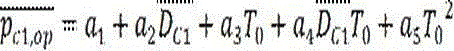
一种热电机组高背压供热优化方法,其特征在于:所述1#机组最佳背压p c1,op是根据机组排汽流量D c1和环境温度T 0如下确定:A method for optimizing heat supply with high back pressure of a thermal power unit, characterized in that: the optimal back pressure p c1 of the 1# unit, op is determined as follows according to the exhaust steam flow D c1 of the unit and the ambient temperature T 0 :

其中,a 1=0.29-0.31; a 2=0.139-0.141;a 3=0.0169-0.0171;a 4=0.0080-0.0081;a 5=0.00068-0.000684Among them, a 1 =0.29-0.31; a 2 =0.139-0.141; a 3 =0.0169-0.0171; a 4 =0.0080-0.0081; a 5 =0.00068-0.000684
T 0为环境温度 T 0 is the ambient temperature


p c1,d和D c1,d分别为1#机组设计背压和设计排汽流量。 p c1,d and D c1,d are the design back pressure and the design exhaust flow of the 1# unit, respectively.
一种热电机组高背压供热优化方法,其特征在于:所述调节2#机组背压至保障供水温度的最经济背压是根据供水温度t w2确定:A method for optimizing heat supply with high back pressure of a thermal power unit, characterized in that: the most economical back pressure for adjusting the back pressure of the 2# unit to ensure the water supply temperature is determined according to the water supply temperature t w2 :
t c2=t w2+δt 2 t c2 = t w2 + δt 2

其中,t c2为p c2对应的饱和温度,2#热网凝汽器传热端差δt 2=2℃-3℃。Among them, t c2 is the saturation temperature corresponding to p c2 , and the heat transfer end difference of the 2# heat network condenser is δt 2 =2℃-3℃.
一种热电机组高背压供热优化方法,其特征在于:所述2#机组在最高背压下运行是当2#机组所有排汽D c2都进入热网凝汽器时的最高背压,其根据如下公式求得:A method for optimizing heat supply with high back pressure of a thermal power unit, characterized in that: the operation of the 2# unit under the highest back pressure is the highest back pressure when all the exhaust steam D c2 of the 2# unit enters the heat network condenser, It is obtained according to the following formula:
1#机组最佳排汽温度t c1,op:Optimal exhaust steam temperature t c1,op of 1# unit:

1#机组热网凝汽器出口循环水温t w1:1# unit heat network condenser outlet circulating water temperature t w1 :

其中,1#热网凝汽器传热端差δt 1=2℃-3℃Among them, 1# heat network condenser heat transfer end difference δt 1 =2℃-3℃
2#机组最高排汽温度t c2,max:The maximum exhaust

t c2,max对应的汽化潜热和压力分别为:The latent heat and pressure of vaporization corresponding to t c2,max are:


一种热电机组高背压供热优化方法,其特征在于:所述调节1#机组背压至保障供水温度的最经济背压是根据供水温度t w2和2#机组最高背压p c2,max确定;A method for optimizing heat supply with high back pressure of a thermal power unit, characterized in that: the most economical back pressure for adjusting the back pressure of the 1# unit to the guaranteed water supply temperature is based on the water supply temperature t w2 and the maximum back pressure p c2,max of the 2# unit Sure;
首先,根据t w2、r 2,max(由p c2,max唯一确定),求2#热网凝汽器进口水温t w1:First, according to t w2 , r 2,max (determined by p c2,max uniquely), find the inlet water temperature t w1 of 2# heat network condenser:

然后根据t w1求1#机组排汽温度t c1和排汽压力p c1:Then find the exhaust steam temperature t c1 and exhaust steam pressure p c1 of 1# unit according to t w1 :

实施本发明上述所提供的一种热电机组高背压供热优化方法,与现有的定背压运行相比,在两台机组高背压串联供热时,在线协同优化两台机组的背压,既保障了热负荷需求,也增加了发电量,实现了供热能耗最小化。By implementing the above-mentioned method for optimizing heat supply of thermal power units provided by the present invention with high back pressure, compared with the existing constant back pressure operation, when two units are connected in series with high back pressure for heat supply, the back pressure of the two units is optimized online collaboratively. It not only guarantees the heat load demand, but also increases the power generation and minimizes the energy consumption for heating.
附图说明Description of drawings
图1是两台热电机组高背压串联供热系统结构示意图。Figure 1 is a schematic diagram of the structure of the high back pressure series heating system of two thermal power units.
具体实施方式Detailed ways
下面对本发明的具体实施方式作出进一步的说明。The specific embodiments of the present invention will be further described below.
如附图1所示,具体实施一种热电机组高背压供热优化方法,该方法的高背压供热系统包括1#热网凝汽器、1#乏汽凝汽器、2#热网凝汽器、2#乏汽凝汽器、蝶阀FC1,1、FC1,2、FC2,1和FC2,2,及1#机排汽装置和2#机排汽装置;温度为tw0、流量为Dw的一次热网循环回水依次流经1#热网凝汽器和2#热网凝汽器,在1#热网凝汽器中被压力为pc1、流量为Dc1,1的1#机排汽加热至tw1,在2#热网凝汽器中被压力为pc2、流量为Dc2,1的2#机排汽加热至供水温度tw2。As shown in FIG. 1, a method for optimizing heat supply with high back pressure of a thermal power unit is specifically implemented. The high back pressure heating system of this method includes 1# heat grid condenser, 1# spent steam condenser, 2# heat Grid condenser, 2# exhausted steam condenser, butterfly valve F C1,1 , F C1,2 , F C2,1 and F C2,2 , and 1# machine exhaust device and 2# machine exhaust device; temperature The circulating return water of the primary heat network with t w0 and flow rate Dw flows through the 1# heat network condenser and the 2# heat network condenser in turn. In the 1# heat network condenser, the pressure is p c1 and the flow rate is The 1# machine exhaust steam of D c1,1 is heated to tw1 , and is heated to the water supply temperature t w2 by the 2 # machine exhaust steam with pressure p c2 and flow rate D c2,1 in the 2# heat network condenser.
在两台机组高背压串联供热时,在1#机组排汽量为D c1、2#机组排汽量D c2、循环水量D w及回水温度t w0下,协同优化1#、2#机组背压p c1和p c2,保障供水温度t w2,并使发电量最大化、供热能耗最小化。When two units are heated in series with high back pressure, when the exhaust steam volume of the 1# unit is D c1 , the exhaust steam volume D c2 of the 2# unit, the circulating water volume D w and the return water temperature t w0 , the 1#, 2 #The unit back pressure p c1 and p c2 ensures the water supply temperature t w2 , maximizes the power generation and minimizes the heating energy consumption.
上述热电机组高背压供热下的协同优化方法包括两大部分:The collaborative optimization method for the above-mentioned thermal power unit under high back pressure heating includes two parts:
一、首先优化1#机组背压为最佳背压,多发电,调节2#机组背压p c2保障供水温度t w2,具体优化计算如下:1. First, optimize the back pressure of the 1# unit to be the best back pressure, generate more power, and adjust the back pressure p c2 of the 2# unit to ensure the water supply temperature t w2 . The specific optimization calculation is as follows:
(1)确定1#机组的最佳背压p c1,op ,其与1#机组排汽量D c1和环境温度T 0有关:(1) Determine the optimal back pressure p c 1 ,op of the 1# unit, which is related to the exhaust steam volume D c1 of the 1# unit and the ambient temperature T 0 :
其中,a 1=0.29-0.31; a 2=0.139-0.141; a 3=0.0169-0.0171; a 4=0.0080-0.0081;a 5=0.00068-0.000684Among them, a 1 =0.29-0.31; a 2 =0.139-0.141; a 3 =0.0169-0.0171; a 4 =0.0080-0.0081; a 5 =0.00068-0.000684
T 0为环境温度 T 0 is the ambient temperature


p c1,d和D c1,d分别为1#机组设计背压和设计排汽流量。 p c1,d and D c1,d are the design back pressure and the design exhaust flow of the 1# unit, respectively.
(2)根据p c1,op 确定对应的排汽温度t c1,op 和汽化潜热r 1:(2) Determine the corresponding exhaust steam temperature t c 1 ,op and the latent heat of vaporization r 1 according to p c 1 ,op :

f 1、f 2函数根据水蒸气物性可直接获得。The f 1 and f 2 functions can be directly obtained from the physical properties of water vapor.
(3)1#热网凝汽器出口水温t w1:(3) 1# heat network condenser outlet water temperature t w1 :

1#热网凝汽器传热端差δt 1 =2℃~3℃1# heat network condenser heat transfer end difference δt 1 =2℃~3℃
(4)1#热网凝汽器进汽热量为(4) 1# heat network condenser inlet steam heat is

(5)1#热网凝汽器进汽量D c1,1 (5) 1# heat network condenser steam intake D c1,1
D c1,1=D c1,1·r 1/r 1 D c1,1 = D c1,1 · r 1 / r 1
(6)1#乏汽凝汽器进汽流量为(6) The inlet steam flow of the 1# exhausted steam condenser is

(7)1#乏汽凝汽器冷却工质流量D a1,op:(7) Cooling medium flow rate D a1,op of 1# exhausted steam condenser:

其中,δt a为乏汽凝汽器的传热端差,空冷取5℃,湿冷取3℃,t a1为环境温度或乏汽冷却循环水入口温度,D a1,op为1#乏汽凝汽器的冷却空气量或循环水量,可根据上式直接求得。Among them, δt a is the heat transfer end difference of the spent steam condenser, 5℃ for air cooling and 3℃ for wet cooling, t a 1 is the ambient temperature or the inlet temperature of the spent steam cooling circulating water, D a1,op is the 1# spent steam The cooling air volume or circulating water volume of the condenser can be directly obtained according to the above formula.
(8)2#热网凝汽器进汽热量(8) Inlet steam heat of 2# heat network condenser

(9)2#机组排汽压力p c2、汽化潜热r 2及热网凝汽器进汽量D c2,1 (9) Exhaust steam pressure p c2 of 2# unit, latent heat of vaporization r 2 and inlet steam volume D c2,1 of the heat network condenser
首先,根据供水温度t w2确定2#机组排汽温度t c2:First, determine the exhaust steam temperature t c2 of the 2# unit according to the water supply temperature t w2 :
t c2=t w2+δt 2 t c2 = t w2 + δt 2
其中,2#热网凝汽器传热端差δt 2=2℃~3℃Among them, 2# heat network condenser heat transfer end difference δt 2 =2℃~3℃
排汽压力p c2和汽化潜热r 2是排汽温度t c2的单一函数:Exhaust steam pressure p c2 and latent heat of vaporization r 2 are a single function of exhaust steam temperature t c2 :


热网凝汽器进汽量D c2,1:Inlet steam volume D c2,1 of the heat network condenser:
D c2,1=D c2,1·r 2/r 2 D c2,1 = D c2,1 · r 2 / r 2
(10)2#乏汽凝汽器冷却工质流量D a2,op:(10) Cooling medium flow rate D a2,op of 2# exhausted steam condenser:

D a2,op为2#乏汽凝汽器的冷却空气量或循环水量,可根据上式直接求得。 D a2,op is the cooling air volume or circulating water volume of the 2# exhausted steam condenser, which can be directly obtained according to the above formula.
(11)2#机组最高背压p c2,max及其对应的温度t c2,max及汽化潜热r 2,max (11) The maximum back pressure p c2,max of the 2# unit and its corresponding temperature t c2,max and the latent heat of vaporization r 2,max
2#机组所有排汽D c2都进入热网凝汽器时的最高背压为p c2,max,其根据t c2,max单一确定:When all the exhaust steam D c2 of the 2# unit enters the condenser of the heat grid, the maximum back pressure is p c2,max , which is determined according to t c2,max :

r 2=

二、当根据供水温度确定的2#机组背压p c2大于p c2,max,则调节1#机组背压p c1至保障供水温度的最经济背压,具体优化计算如下:2. When the back pressure p c2 of the 2# unit determined according to the water supply temperature is greater than p c2,max , adjust the back pressure p c1 of the 1# unit to the most economical back pressure to ensure the water supply temperature. The specific optimization calculation is as follows:
(1)进行判断,若p c2>p c2,max,则调节p c1保证供水温度t w2。(1) Judging, if p c2 > p c2,max , adjust p c1 to ensure the water supply temperature t w2 .
(2)根据供水温度t w2和2#机组最高背压p c2,max确定1#机组背压p c1:(2) Determine the back pressure p c1 of the 1# unit according to the water supply temperature t w2 and the maximum back pressure p c2,max of the 2# unit:
首先,根据t w2、p c2,max求2#热网凝汽器进口水温t w1:First of all, according to t w2 , p c2,max to find the inlet water temperature t w1 of 2# heat network condenser:

然后根据t w1求1#机组排汽温度t c1和排汽压力p c1:Then find the exhaust steam temperature t c1 and exhaust steam pressure p c1 of 1# unit according to t w1 :

r 1=f 2(t c1) r 1 = f 2 ( t c1 )
(3)1#机组最高背压p c1,max及其对应的温度t c1,max及汽化潜热r 1,max为:(3) The maximum back pressure p c1,max of the 1# unit and its corresponding temperature t c1,max and the latent heat of vaporization r 1,max are:


(4)判断是否可通过调p c1满足供水温度t w2 (4) Determine whether the water supply temperature t w2 can be satisfied by adjusting p c1
若|t c1-t c1,max|≤1.5,满足,进行下面(5)式计算;If | t c1 - t c1,max | ≤ 1.5, the following formula (5) is performed;
若|t c1-t c1,max|>1.5,不满足,切换至抽汽供热模式;If | t c1 - t c1,max | > 1.5, it is not satisfied, switch to extraction steam heating mode;
(5)1#热网凝汽器进汽流量D c1,1:(5) Inlet steam flow D c1,1 of 1# heat network condenser:

(6)1#乏汽凝汽器冷却工质流量D a1,op:(6) Cooling medium flow rate D a1,op of 1# exhausted steam condenser:

上述具体实施方式,实现了两台机组高背压串联供热时,在线协同优化两台机组的背压,保障了热负荷需求,也增加了发电量,实现了供热能耗最小。The above-mentioned specific embodiment realizes that when two units are connected in series with high back pressure for heating, the back pressure of the two units is optimized online, which ensures the heat load demand, increases the power generation, and realizes the minimum heating energy consumption.
具体实施例1Specific Example 1
如附图1所示,具体实施一种两台热电机组高背压供热协同优化方法,温度为t w0、流量为D w的一次热网循环回水依次流经1#热网凝汽器和2#热网凝汽器,在1#热网凝汽器中被压力为p c1、流量为D c1,1的1#机排汽加热至t w1,在2#热网凝汽器中被压力为p c2、流量为D c2,1的2#机排汽加热至t w2,本发明的高背压供热优化实施方案如下:As shown in accompanying drawing 1, a kind of synergistic optimization method for high back pressure heating supply of two thermal power units is specifically implemented, and the circulating return water of the primary heat network with temperature t w0 and flow rate D w flows through the 1# heat network condenser in turn And 2# heat network condenser, in 1# heat network condenser, it is heated to t w1 by 1# machine exhaust steam with pressure p c1 and flow rate D c1,1 , in 2# heat network condenser It is heated to t w2 by the exhaust steam of 2# machine with pressure p c2 and flow rate D c2,1 . The optimized implementation of high back pressure heat supply of the present invention is as follows:
首先,实施1#机组在最佳背压下运行、调节2#机组背压p c2保障供水温度t w2的优化方案;根据1#机组排汽流量D c1和环境温度T 0计算得到1#机最佳背压p c1,op,然后根据热平衡计算得到1#热网凝汽器进汽流量D c1,1、1#机乏汽凝汽器进汽流量D c1,2及1#乏汽凝汽器冷却工质流量D a1,op,依据D c1,2确定蝶阀Fc1,2开度,蝶阀Fc1,1开度不调整,处于全开状态,再依据D a1,op调整1#机组冷却空气量或循环水量,获得最佳背压pc1,op;根据供水温度t w2计算得到2#机背压p c2,再通过热平衡计算得到2#热网凝汽器进汽流量D c2,1、2#机乏汽凝汽器进汽流量D c2,2及2#乏汽凝汽器冷却工质流量D a2,op,依据D c2,2确定蝶阀Fc2,2开度,蝶阀Fc2,1开度不调整,处于全开状态,再依据Da2,op调整2#机冷却空气量或循环水量,实时获得保障供水温度t w2的经济背压p c2。First, implement the optimization scheme of running the 1# unit under the optimal back pressure and adjusting the back pressure p c2 of the 2# unit to ensure the water supply temperature t w2 ; according to the exhaust steam flow D c1 of the 1# unit and the ambient temperature T 0 , the 1# unit is calculated. The optimal back pressure p c1,op , and then according to the heat balance calculation, the inlet steam flow D c1,1 of the 1# heat grid condenser, the inlet steam flow D c1,2 of the 1# exhaust steam condenser and the 1# exhaust steam condenser are obtained. The cooling medium flow rate D a1,op of the steam generator is determined according to D c1,2 to determine the opening degree of butterfly valve F c1,2 , the opening degree of butterfly valve F c1,1 is not adjusted and is in a fully open state, and then adjust the 1# unit according to D a1,op Cooling air volume or circulating water volume to obtain the optimal back pressure p c1,op ; calculate the 2# machine back pressure p c2 according to the water supply temperature t w2 , and then obtain the 2# heat network condenser inlet steam flow D c2 through heat balance calculation, 1. The inlet steam flow D c2,2 of the 2# exhausted steam condenser and the cooling medium flow D a2,op of the 2# exhausted steam condenser, determine the opening degree of the butterfly valve F c2,2 according to D c2,2 , and the butterfly valve F The opening of c2,1 is not adjusted, it is in the fully open state, and then the cooling air volume or circulating water volume of the 2# machine is adjusted according to D a2,op , and the economic back pressure p c2 that guarantees the water supply temperature t w2 is obtained in real time.
计算确定当2#机组所有排汽都进入热网凝汽器时的最高背压p c2,max。若根据供水温度t w2确定的2#机组背压p c2大于最高背压p c2,max时,则2#机组维持最高背压运行,调节1#机组背压p c1保供热;优化计算中,首先判断p c2是否大于p c2,max,若否,则实施上述的1#机组在最佳背压下运行、调节2#机组背压p c2保障供水温度t w2的优化方案;若是,则实施下述的2#机组最高背压p c2,max运行、调节1#机组背压p c1保证供水温度t w2的优化方案。The calculation determines the maximum back pressure p c2,max when all the exhaust steam of the 2# unit enters the condenser of the heat grid. If the back pressure p c2 of the 2# unit determined according to the water supply temperature t w2 is greater than the maximum back pressure p c2,max , the 2# unit will maintain the highest back pressure operation, and the back pressure p c1 of the 1# unit will be adjusted to ensure heat supply; in the optimization calculation , first determine whether p c2 is greater than p c2,max , if not, implement the above-mentioned optimization scheme of running the 1# unit under the optimal back pressure and adjusting the back pressure p c2 of the 2# unit to ensure the water supply temperature t w2 ; if so, then Implement the following optimization scheme of running the maximum back pressure p c2,max of the 2# unit and adjusting the back pressure p c1 of the 1# unit to ensure the water supply temperature t w2 .
实施2#机组最高背压p c2,max运行,调节1#机组背压p c1保障供水温度t w2的优化方案;根据供水温度t w2和2#机组最高背压p c2,max计算得到1#机背压p c1及其对应的温度t c1,然后通过热平衡计算得到1#机组最高背压p c1,max对应的t c1,max,若|t c1-t c1,max|>1.5,表示高背压供热不能满足供热负荷需求,切换至抽汽供热模式,若|t c1-t c1,max|≤1.5,则根据热平衡计算得到1#热网凝汽器进汽流量D c1,1、1#机乏汽凝汽器进汽流量D c1,2及1#乏汽凝汽器冷却工质流量D a1,op,根据D c1,2确定蝶阀Fc1,2开度,蝶阀Fc1,1开度不调整,处于全开状态,再依据Da1,op调整1#机冷却空气量或循环水量,获得保障供水温度t w2的背压p c1;此时,2#机背压为最高背压p c2,max,2#机排汽全部进入2#热网凝汽器,蝶阀Fc2,2全关,蝶阀Fc2,1全开,2#乏汽凝汽器冷却工质流量D a2,op为0。Implement the maximum back pressure p c2,max operation of the 2# unit, and adjust the back pressure p c1 of the 1# unit to ensure the optimal plan of the water supply temperature t w2 ; according to the water supply temperature t w2 and the maximum back pressure p c2,max of the 2# unit, calculate the 1# machine back pressure p c1 and its corresponding temperature t c1 , and then obtain the t c1 ,max corresponding to the highest back pressure p c1,max of the 1# unit through heat balance calculation, if | t c1 - t c1,max |>1.5, it means high If the back pressure heating cannot meet the heating load demand, switch to the steam extraction heating mode, if | t c1 - t c1 , max | 1. The inlet steam flow D c1,2 of the 1# exhaust steam condenser and the cooling working fluid flow D a1,op of the 1# exhaust steam condenser, determine the opening degree of the butterfly valve F c1,2 according to D c1,2 , and the butterfly valve F The opening of c1,1 is not adjusted, it is in a fully open state, and then the cooling air volume or circulating water volume of the 1# machine is adjusted according to D a1,op to obtain the back pressure p c1 that guarantees the water supply temperature t w2 ; at this time, the back pressure of the 2# machine It is the highest back pressure p c2,max , the exhaust steam of 2# machine all enters the 2# heat grid condenser, the butterfly valve F c2,2 is fully closed, the butterfly valve F c2,1 is fully opened, and the cooling medium of the 2# exhaust steam condenser The flow rate D a2,op is zero.
Claims (1)


Priority Applications (1)
| Application Number | Priority Date | Filing Date | Title |
|---|---|---|---|
| CN202110408696.1A CN113074402B (en) | 2021-04-16 | 2021-04-16 | Optimization method of high back pressure heat supply for thermal power units |
Applications Claiming Priority (1)
| Application Number | Priority Date | Filing Date | Title |
|---|---|---|---|
| CN202110408696.1A CN113074402B (en) | 2021-04-16 | 2021-04-16 | Optimization method of high back pressure heat supply for thermal power units |
Publications (2)
| Publication Number | Publication Date |
|---|---|
| CN113074402A CN113074402A (en) | 2021-07-06 |
| CN113074402B true CN113074402B (en) | 2022-07-19 |
Family
ID=76617659
Family Applications (1)
| Application Number | Title | Priority Date | Filing Date |
|---|---|---|---|
| CN202110408696.1A Active CN113074402B (en) | 2021-04-16 | 2021-04-16 | Optimization method of high back pressure heat supply for thermal power units |
Country Status (1)
| Country | Link |
|---|---|
| CN (1) | CN113074402B (en) |
Citations (6)
| Publication number | Priority date | Publication date | Assignee | Title |
|---|---|---|---|---|
| JP2010275925A (en) * | 2009-05-28 | 2010-12-09 | Toshiba Corp | Steam turbine power generation facility and operation method thereof |
| CN206683027U (en) * | 2017-03-30 | 2017-11-28 | 华北电力大学 | A kind of high back pressure two-stage heating system system that vapour source is adjusted using injector |
| CN110005488A (en) * | 2019-02-22 | 2019-07-12 | 华电电力科学研究院有限公司 | A kind of high back pressure energy saving in heating system optimization method |
| CN110220234A (en) * | 2019-03-11 | 2019-09-10 | 华电电力科学研究院有限公司 | A kind of heating system and its working method optimized based on heat supply network circulating water flow and the temperature difference |
| CN111352400A (en) * | 2020-03-13 | 2020-06-30 | 中国大唐集团科学技术研究院有限公司华东电力试验研究院 | A sliding pressure operation optimization method and sliding pressure operation control system of a heating unit |
| CN211119594U (en) * | 2019-11-25 | 2020-07-28 | 中国大唐集团科学技术研究院有限公司西北电力试验研究院 | An air-cooled unit double back pressure series cascade heating system |
Family Cites Families (3)
| Publication number | Priority date | Publication date | Assignee | Title |
|---|---|---|---|---|
| KR20180132777A (en) * | 2016-03-31 | 2018-12-12 | 인벤티스 써멀 테크놀로지스 인코포레이티드 | Combustion systems including temperature swing adsorption gas separation |
| CN107366560B (en) * | 2017-08-30 | 2019-08-13 | 中国大唐集团科学技术研究院有限公司西北分公司 | A kind of exhaust steam pressure optimization method of wet type cooling unit steam turbine |
| CN112554980B (en) * | 2020-11-25 | 2022-03-22 | 西安交通大学 | A kind of double back pressure supercritical carbon dioxide polygeneration system and operation method |
-
2021
- 2021-04-16 CN CN202110408696.1A patent/CN113074402B/en active Active
Patent Citations (6)
| Publication number | Priority date | Publication date | Assignee | Title |
|---|---|---|---|---|
| JP2010275925A (en) * | 2009-05-28 | 2010-12-09 | Toshiba Corp | Steam turbine power generation facility and operation method thereof |
| CN206683027U (en) * | 2017-03-30 | 2017-11-28 | 华北电力大学 | A kind of high back pressure two-stage heating system system that vapour source is adjusted using injector |
| CN110005488A (en) * | 2019-02-22 | 2019-07-12 | 华电电力科学研究院有限公司 | A kind of high back pressure energy saving in heating system optimization method |
| CN110220234A (en) * | 2019-03-11 | 2019-09-10 | 华电电力科学研究院有限公司 | A kind of heating system and its working method optimized based on heat supply network circulating water flow and the temperature difference |
| CN211119594U (en) * | 2019-11-25 | 2020-07-28 | 中国大唐集团科学技术研究院有限公司西北电力试验研究院 | An air-cooled unit double back pressure series cascade heating system |
| CN111352400A (en) * | 2020-03-13 | 2020-06-30 | 中国大唐集团科学技术研究院有限公司华东电力试验研究院 | A sliding pressure operation optimization method and sliding pressure operation control system of a heating unit |
Also Published As
| Publication number | Publication date |
|---|---|
| CN113074402A (en) | 2021-07-06 |
Similar Documents
| Publication | Publication Date | Title |
|---|---|---|
| CN109854313B (en) | A flexible coal-fired power generation system and operation method | |
| CN110469835A (en) | Thermoelectric decoupling system and operation method based on absorption heat pump and heat storage equipment | |
| CN112611010B (en) | A kind of regulation method for flexible regulation system of power generation load of multi-heat source cogeneration unit | |
| CN108317767B (en) | Proton exchange membrane fuel cell waste heat utilization system and method | |
| CN111649372A (en) | A back pressure heating system and method suitable for small circulating water flow | |
| CN110159371B (en) | System and method for cylinder cutting operation of multi-low pressure cylinder steam turbine under partial load | |
| CN112283697B (en) | Direct air-cooling unit cold end exhaust steam waste heat utilization system combined with absorption heat pump | |
| CN109441577A (en) | Absorption heat pump cogeneration units recirculated cooling water tower operation method above freezing | |
| CN111256204B (en) | Heat supply optimization method of coupled absorption heat pump in thermal power plant | |
| CN115218247A (en) | Low-grade waste heat recovery system for steel plant for central heating | |
| CN113074402B (en) | Optimization method of high back pressure heat supply for thermal power units | |
| KR100821960B1 (en) | Energy Saving District Heating Method Using Recovery Hot Water for Heating | |
| CN112484129B (en) | Thermoelectric decoupling system of thermoelectric unit and operation method | |
| WO2023029404A1 (en) | Efficient and flexible heat supply and power generation system capable of achieving energy cascade recycling | |
| CN114837812B (en) | Gas turbine air inlet temperature regulating system and method for distributed energy back pressure unit | |
| CN116344863B (en) | Combined heat and power thermal management system of multi-fuel cell system and control method thereof | |
| CN116398296B (en) | A precise heat extraction combined cycle intake cooling and heating circulation system | |
| CN112902501B (en) | Direct-fired lithium bromide absorption heat pump unit with load balancing condenser | |
| EP4431829A1 (en) | Heat recovery device, heat recovery method, and steel sheet manufacturing method | |
| CN106401679A (en) | Thermoelectric unit with peak regulation and heat storage functions | |
| CN214468562U (en) | A chemical water cascade heating system utilizing waste heat | |
| CN213574260U (en) | An energy saving and emission reduction system using urban water supply as condenser cooling water | |
| CN214221275U (en) | An extraction steam cogeneration unit suitable for primary frequency modulation of large extraction steam | |
| CN214247506U (en) | Device for increasing air inlet temperature of combustion engine by using closed cooling water | |
| CN111347838B (en) | A waste heat recovery air treatment device |
Legal Events
| Date | Code | Title | Description |
|---|---|---|---|
| PB01 | Publication | ||
| PB01 | Publication | ||
| SE01 | Entry into force of request for substantive examination | ||
| SE01 | Entry into force of request for substantive examination | ||
| GR01 | Patent grant | ||
| GR01 | Patent grant |