CN113065296B - Different-modal stable switching control algorithm based on order reduction - Google Patents
Different-modal stable switching control algorithm based on order reduction Download PDFInfo
- Publication number
- CN113065296B CN113065296B CN202110338100.5A CN202110338100A CN113065296B CN 113065296 B CN113065296 B CN 113065296B CN 202110338100 A CN202110338100 A CN 202110338100A CN 113065296 B CN113065296 B CN 113065296B
- Authority
- CN
- China
- Prior art keywords
- order
- zero
- follows
- poles
- pole
- Prior art date
- Legal status (The legal status is an assumption and is not a legal conclusion. Google has not performed a legal analysis and makes no representation as to the accuracy of the status listed.)
- Active
Links
Images


Classifications
-
- G—PHYSICS
- G06—COMPUTING OR CALCULATING; COUNTING
- G06F—ELECTRIC DIGITAL DATA PROCESSING
- G06F30/00—Computer-aided design [CAD]
- G06F30/30—Circuit design
-
- G—PHYSICS
- G06—COMPUTING OR CALCULATING; COUNTING
- G06F—ELECTRIC DIGITAL DATA PROCESSING
- G06F17/00—Digital computing or data processing equipment or methods, specially adapted for specific functions
- G06F17/10—Complex mathematical operations
- G06F17/11—Complex mathematical operations for solving equations, e.g. nonlinear equations, general mathematical optimization problems
Landscapes
- Engineering & Computer Science (AREA)
- Physics & Mathematics (AREA)
- General Physics & Mathematics (AREA)
- Theoretical Computer Science (AREA)
- Mathematical Physics (AREA)
- Pure & Applied Mathematics (AREA)
- Computer Hardware Design (AREA)
- Data Mining & Analysis (AREA)
- General Engineering & Computer Science (AREA)
- Computational Mathematics (AREA)
- Mathematical Analysis (AREA)
- Mathematical Optimization (AREA)
- Geometry (AREA)
- Operations Research (AREA)
- Algebra (AREA)
- Evolutionary Computation (AREA)
- Databases & Information Systems (AREA)
- Software Systems (AREA)
- Feedback Control In General (AREA)
Abstract
The invention discloses a different-mode stable switching control algorithm based on order reduction, which comprises the following steps: (1) the second-order over-damping controllable system firstly configures two poles and a zero of the second-order over-damping controllable system through a transfer function G (S); (2) the value of one of the poles is identical to that of the zero, cancellation is realized, one pole which is not cancelled is left, zero-pole cancellation is achieved, reduction of the second-order over-damping controllable system is completed, and the second-order over-damping controllable system is reduced to a first-order system; (3) after order reduction, the first-order system realizes zero-error switching of modes. The invention aims at a second-order over-damping controllable system, can realize the random configuration of poles, and can reduce the order of the system into a first-order system by offsetting the zero pole through state feedback. Therefore, the mode and the stable conversion between the modes are conveniently realized, and the stable conversion can be realized by combining master-slave control, prediction control and the like.
Description
Technical Field
The invention relates to the field of intelligent control, in particular to a different-mode stable switching control algorithm based on order reduction.
Background
The control system performance is mainly embodied in two aspects: the first is response speed and the second is control accuracy. If the intelligent control multi-mode is considered, the intelligent control multi-mode can be completely divided into two modes, wherein one mode is a mode for improving the response speed, and the other mode is a mode for improving the control precision. The core of intelligent control is multi-modal control, and the difficulty of multi-modal control is smooth conversion between modes.
Some studies have been conducted on smooth transition between different modes in various countries, for example, a weighting method is adopted to make the fluctuation generated when the modes are transitioned smaller. A second or higher order system, without reduction, is difficult to smoothly transition from a first mode of speed emphasis to a second mode of accuracy emphasis without fluctuations, whereas a first order system may smoothly transition from a first mode of speed emphasis to a second mode of accuracy emphasis without fluctuations.
In view of this, the invention provides a reduced-order based different-mode stable switching control algorithm.
Disclosure of Invention
The invention aims to provide a different-mode stable switching control algorithm based on reduced order aiming at the defects of the prior art.
In order to solve the technical problems, the following technical scheme is adopted:
a different modal stability switching control algorithm based on order reduction comprises the following steps:
(1) the second-order over-damping controllable system firstly configures two poles and a zero of the second-order over-damping controllable system through a transfer function G (S);
(2) the value of one of the poles is identical to that of the zero, cancellation is achieved, a pole which is not cancelled is left, zero-pole cancellation is achieved, reduction of the second-order over-damping controllable system is completed, and the second-order over-damping controllable system is reduced to a first-order system;
(3) after order reduction, the first-order system realizes zero-error switching of modes.
Further, in step (1), the pole allocation step is as follows:
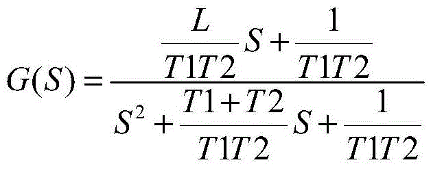
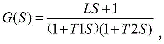
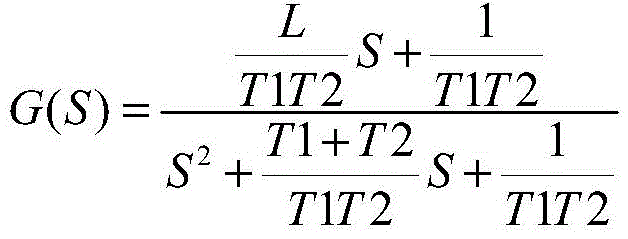
(a) firstly, the transfer function of the second-order over-damping controllable system is assumed as follows:

(b) and then converting the second-order system of the transfer function G (S) into a standard energy control type as follows:
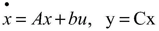
(c) then, a dynamic equation is converted into
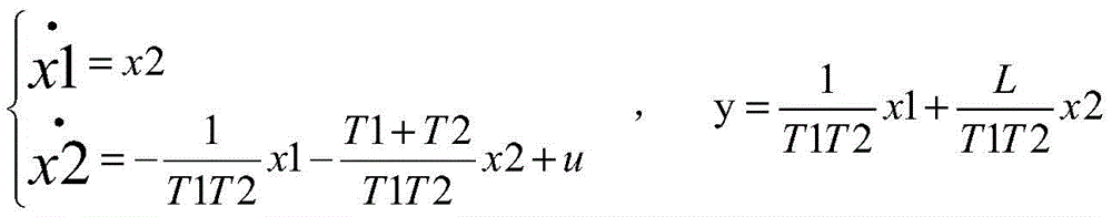
Wherein x1 and x2 are a group of state variables of a second-order over-damping controllable system, u is an input quantity, and y is an output quantity;
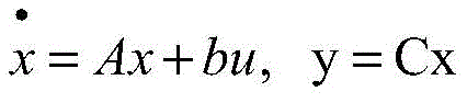
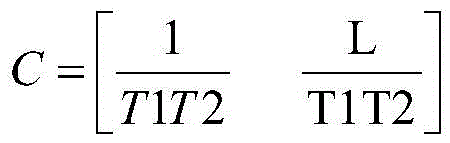
if the dynamic equation is expressed as follows

Then the user can either, for example,

(d) and finally introducing state feedback K ═ K1K 2, wherein a characteristic equation after introducing the state feedback is as follows:
det(SI-A+bK)=0
wherein I is an identity matrix, det represents a determinant of the matrix SI-A + bK
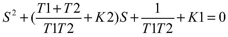
And (3) after simplification:

if the poles required to be configured are β 1, β 2, the characteristic equation thus formed is:
(S- β 1) (S- β 2) ═ 0, i.e.: s2-(β1+β2)S+β1β2=0
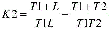
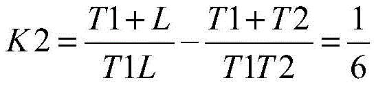
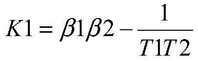
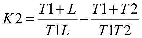
This gives the value of K1, K2:
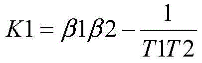
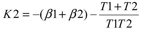
k1 and K2 are determined, and β 1 and β 2 are obtained to realize arbitrary arrangement of poles.
Further, in the step (2), the step of reducing the second-order over-damping controllable system to a first-order system is as follows:
(a) needleFor the transfer function G (S), two poles are provided, respectively And
And zero point has one, is
(b) In order to realize zero-pole cancellation, the value of one pole is the same as that of the zero, cancellation is realized, and the other pole which is not cancelled is left;
(c) after state feedback, the allocated poles are respectively And
And and (3) solving a state feedback matrix according to the formula of the obtained K1 and K2 values:

obtaining a transfer function T (S) after state feedback as follows:

and solving the transfer function T (S) after state feedback, thereby realizing order reduction.
Further, in step (3), the step of the first-order system implementing zero-error switching of the modality is as follows:
(a) at the beginning, assume the output is 0; for the said channel state inverseIf the control target value is Y0, the control value in steady state is calculated as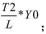
(b) The start control amount is determined to be P0, and the larger | P0| is, the faster the response speed is;
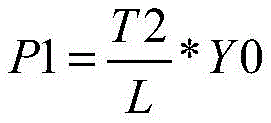
(c) when the output value is Y0, the control amount is switched to P1, and the P1 value is as follows:
(d) and on the basis of successful switching, fine adjustment control is performed to realize zero-error switching of the modes.
Further, in step (3), the modalities are divided according to a state space.
Further, the mode is divided according to the state space according to the error size.
Due to the adoption of the technical scheme, the method has the following beneficial effects:
the invention relates to a different modal stable switching control algorithm based on order reduction, which can realize arbitrary pole allocation aiming at a second-order over-damping controllable system, and can cancel the zero pole through state feedback so as to reduce the order of the system into a first-order system. Therefore, the mode and the stable conversion between the modes are conveniently realized, and the stable conversion can be realized by combining master-slave control, prediction control and the like.
Aiming at a second-order over-damping system, the system is divided into two modes firstly, the first mode emphasizes to improve the response speed, the second mode emphasizes to improve the control precision, and the order of the second-order over-damping controllable system is reduced, so that the mode is switched without fluctuation.
Drawings
The invention will be further described with reference to the accompanying drawings in which:
FIG. 1 is a block diagram of smooth switching of different modes of a second-order over-damping controllable system based on order reduction in the invention;
FIG. 2 is a block diagram of a verification example of a smooth switching control algorithm between different modes of a second-order over-damping system based on order reduction according to the present invention;
FIG. 3 is an output diagram of an example of a reduced order based verification of a smooth transition control algorithm between different modes in accordance with the present invention;
FIG. 4 is a second output diagram of a verification example of a smooth handover control algorithm between different modes based on reduced order in the present invention.
Detailed Description
In order to make the objects, technical solutions and advantages of the present invention more apparent, the present invention is further described in detail below with reference to the accompanying drawings and examples. It should be understood, however, that the description herein of specific embodiments is only intended to illustrate the invention and not to limit the scope of the invention. Moreover, in the following description, descriptions of well-known structures and techniques are omitted so as to not unnecessarily obscure the concepts of the present invention.
As shown in fig. 1 to 4, a reduced-order based stable switching control algorithm with different modes can realize arbitrary configuration of poles for a second-order over-damping controllable system, and reduce the order of the system into a first-order system by canceling the zero pole through state feedback. The method and the device are convenient to realize the mode and the stable conversion between the modes, and the stable conversion can be realized by combining master-slave control, prediction control and the like.
The second-order or high-order over-damping system can not realize error-free switching between the two modes without reducing the order. The second-order over-damping controllable system enables the zero-pole to be offset through the configuration of the poles, so that the order reduction of the second-order over-damping system is completed, and the second-order over-damping system is reduced to a first-order system. While a first order system can achieve error-free switching between the two modes.
Aiming at a second-order over-damping system, the system is divided into two modes firstly, the first mode emphasizes to improve the response speed, the second mode emphasizes to improve the control precision, and the order of the second-order over-damping controllable system is reduced, so that the mode is switched without fluctuation.
Specifically, the realization of error-free switching between the two modes enables the fluctuation in the mode switching process to be small, and the control algorithm is favorable for improving the control precision of a second-order over-damping control system.
Specifically, the first order system can implement ripple-free switching between two simple modalities without feedback, while the second order system can hardly implement ripple-free switching between two modalities without feedback. In order to achieve ripple-free switching between the two modes at the second order, the second order system must be reduced. One of the methods of order reduction is to cancel the pole-zero by arbitrarily configuring the pole. The energy control system can completely realize the arbitrary configuration of poles through state feedback, and achieve the cancellation of zero poles, thereby finishing the purpose of order reduction.
The algorithm specifically comprises the following steps:
step (1): the second-order over-damping controllable system firstly configures two poles and a zero of the second-order over-damping controllable system through a transfer function G (S).
Specifically, in step (1), the pole arrangement steps are as follows:
(a) firstly, the transfer function of the second-order over-damping controllable system is assumed as follows:
(b) and then converting the second-order system of the transfer function G (S) into a standard energy control type as follows:

(c) then, a dynamic equation is converted into

Wherein x1 and x2 are a group of state variables of a second-order over-damping controllable system, u is an input quantity, and y is an output quantity;
if the dynamic equation is expressed as follows
Then the user can either, for example,

(d) and finally introducing state feedback K ═ K1K 2, wherein a characteristic equation after introducing the state feedback is as follows:
det(SI-A+bK)=0
wherein I is an identity matrix, det represents a determinant of the matrix SI-A + bK
And (3) after simplification:

if the poles required to be configured are β 1, β 2, the characteristic equation thus formed is:
(S- β 1) (S- β 2) ═ 0, i.e.: s2-(β1+β2)S+β1β2=0
This gives the value of K1, K2:

k1 and K2 are determined, and β 1 and β 2 are obtained to realize arbitrary arrangement of poles.
Step (2): the value of one of the poles is identical to that of the zero, cancellation is realized, one pole which is not cancelled is left, zero-pole cancellation is achieved, reduction of the second-order over-damping controllable system is completed, and the second-order over-damping controllable system is reduced to a first-order system;
specifically, in this embodiment, in the step (2), the step of reducing the second-order over-damping controllable system to the first-order system is as follows:
(a) for the transfer function G (S), there are two poles, respectively And
And zero point has one, is
(b) In order to realize zero-pole cancellation, the value of one pole is the same as that of the zero, cancellation is realized, and the other pole which is not cancelled is left;
(c) after state feedback, the allocated poles are respectively And
And and (3) solving a state feedback matrix according to the formula of the obtained K1 and K2 values:


the transfer function after state feedback is obtained as follows:
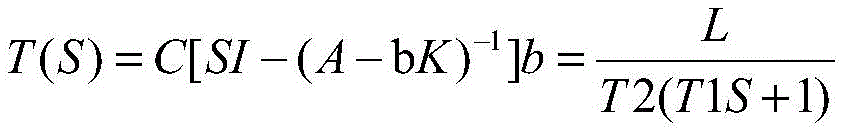
and solving the transfer function T (S) after state feedback, thereby realizing order reduction.
And (3): after order reduction, the first-order system realizes zero-error switching of modes.
Specifically, in this embodiment, in step (3), the step of the first-order system implementing zero-error switching of the modality is as follows:
(a) at the beginning, assume the output is 0; for the reduced-order first-order system of the transfer function T (S) after the state feedback, if the control target value is Y0, the control value in the steady state is calculated as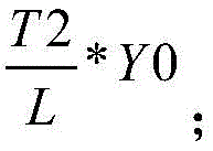
(b) The start control amount is determined to be P0, and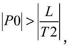 the larger | P0| is, the faster the response speed is;
(c) when the output value is Y0, the control amount is switched to P1, and the P1 value is as follows:
(d) and on the basis of successful switching, fine adjustment control is performed to realize zero-error switching of the modes.
Specifically, in the present embodiment, the modalities are divided according to a state space.
More specifically, the modes are divided according to the state space according to the error size. When the absolute value of the error is larger, entering a mode of improving the response speed; and when the absolute value of the error is smaller, entering a mode of improving the control precision.
No matter how large the first mode control quantity is, the error-free switching between the two modes can be realized, so that the control algorithm of the invention can improve the response speed of the second-order over-damping control system.
Under the condition of interference, the control algorithm can be combined with another control algorithm, the response speed of a second-order over-damping control system is increased, and the control precision is improved.
Specifically, the application to the present embodiment is as follows:
aiming at a second-order over-damping system, if the order is not reduced among different modes, the fluctuation-free switching is difficult to realize. Therefore, a control algorithm for smooth switching between different modes of a second-order over-damping system based on reduced order is needed.
If the controlled object is: wherein, T1 is 1, T2 is 3 and L is 2.
If the dynamic equation is expressed by the formula (4), that is
Wherein,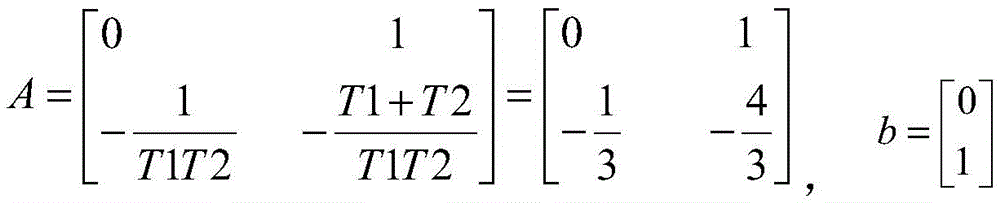

for the controlled object shown in the above formula, there are two poles, each being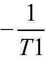 And
And namely-1 and
 and only one zero point is provided, is
 Namely, it is
 To implement zero-pole cancellation, assume the poles after state feedback are-1 and-1, respectively
 According to the formula of the obtained K1 and K2 values, the elements of the state feedback matrix are obtained as follows:

the transfer function after state feedback is obtained as follows:
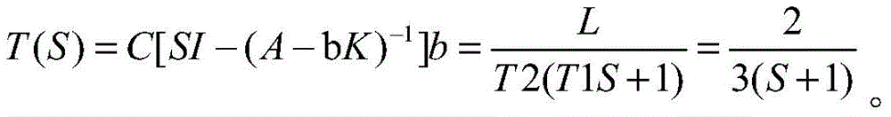
in the above feedback-based transfer function, has already been cancelled, leaving only the-1 pole.
See in particular fig. 2. FIG. 2 is a block diagram of an example of verification of a smooth switching control algorithm between different modes of a second-order over-damping system based on order reduction. Smooth transitions between modalities are mainly considered. The second-order system is difficult to realize the non-fluctuation conversion among different modes, so the first step is carried out with the step reduction; and step two, respectively controlling according to the modes.
Referring to fig. 3 and 4, in the first mode, the control amount of the first mode is 20 and 60, respectively, mainly considering the response time, and since the target value is set to 1, when the output value reaches 1, the control is switched to the second mode, which focuses on the condition of satisfying robustness, and the control accuracy is improved as much as possible. The control model after order reduction is as follows: therefore, when the output is 1, the control amount must be around 1.5.
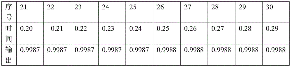
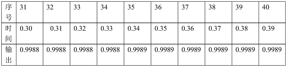
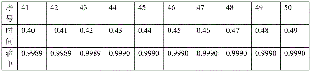
Referring to fig. 3 and 4, fig. 3 shows an output when the initial state is 0 and the first-mode control amount P0 is 20, and fig. 4 shows an output when the initial state is 0 and the first-mode control amount P0 is 60. From the output result, it is effective to smoothly switch the control algorithm between different states based on the reduced order, and in addition, the response speed is faster when the first-modality control amount is larger.
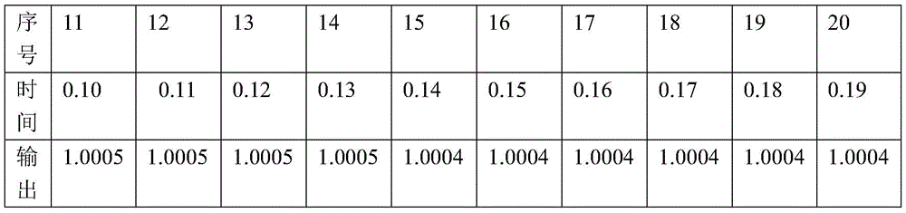
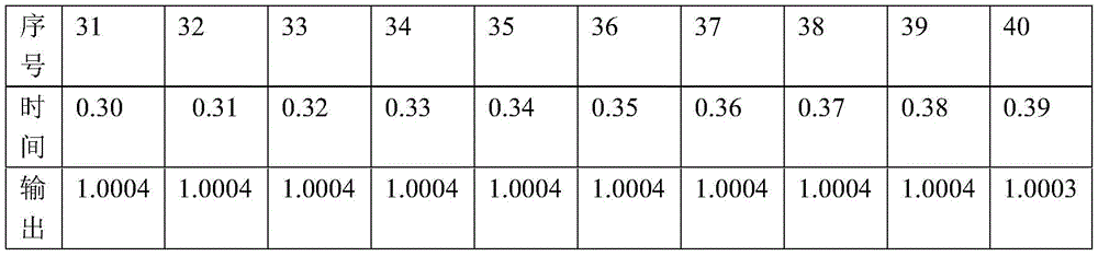
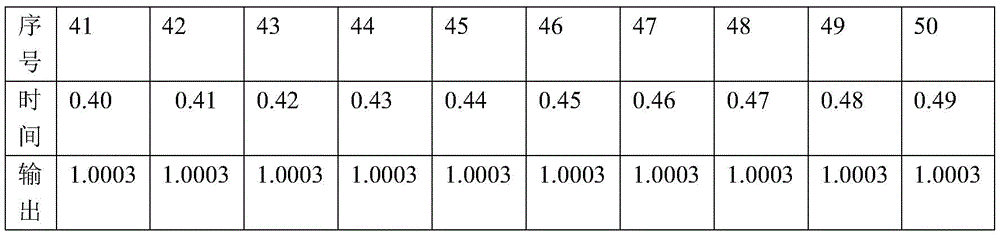
Referring to table 1, table 1 verifies example data (corresponding to fig. 3) for the smooth transition control algorithm between different modalities based on order reduction.
TABLE 1


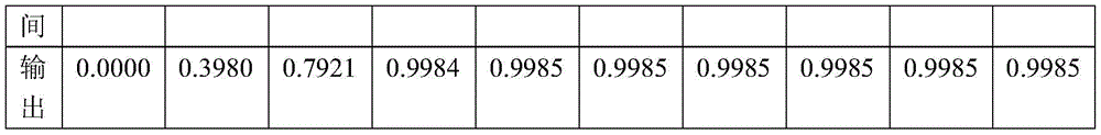
Referring to Table 2, Table 2 shows example data for the control algorithm verification for smooth transition between different modes based on order reduction (corresponding to FIG. 4)
TABLE 2


The above is only a specific embodiment of the present invention, but the technical features of the present invention are not limited thereto. Any simple changes, equivalent substitutions or modifications made on the basis of the present invention to solve the same technical problems and achieve the same technical effects are all covered in the protection scope of the present invention.
Claims (5)
1. A reduced-order based different-mode stable switching control algorithm is characterized by comprising the following steps:
(1) the second-order over-damping controllable system firstly configures two poles and a zero of the second-order over-damping controllable system through a transfer function G (S);
in step (1), the pole allocation step is as follows:
(a) firstly, the transfer function of the second-order over-damping controllable system is assumed as follows:
(b) and then converting the second-order system of the transfer function G (S) into a standard energy control type as follows:
(c) then, a dynamic equation is converted into

Wherein x1 and x2 are a group of state variables of a second-order over-damping controllable system, u is an input quantity, and y is an output quantity;
if the dynamic equation is expressed as follows
Then it is determined that,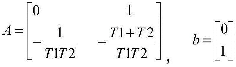
(d) and finally introducing state feedback K ═ K1K 2, wherein a characteristic equation after introducing the state feedback is as follows:
det(SI-A+bK)=0
wherein I is an identity matrix, det represents a determinant of the matrix SI-A + bK
And (3) after simplification:
if the poles required to be configured are β 1, β 2, the characteristic equation thus formed is:
(S- β 1) (S- β 2) ═ 0, i.e.: s. the2-(β1+β2)S+β1β2=0
This gives the value of K1, K2:

k1 and K2 are determined, beta 1 and beta 2 are solved, and arbitrary arrangement of poles is realized;
(2) the value of one of the poles is identical to that of the zero, cancellation is realized, one pole which is not cancelled is left, zero-pole cancellation is achieved, reduction of the second-order over-damping controllable system is completed, and the second-order over-damping controllable system is reduced to a first-order system;
(3) after order reduction, the first-order system realizes zero-error switching of modes.
2. The reduced order based different modal stationary switching control algorithm of claim 1, wherein: in the step (2), the step of reducing the second-order over-damping controllable system to a first-order system is as follows:
(a) for the transfer function G (S), there are two poles, respectively And
And zero point has one, is
(b) In order to realize zero-pole cancellation, the value of one pole is the same as that of the zero, cancellation is realized, and the other pole which is not cancelled is left;
(c) after state feedback, the allocated poles are respectively And
And and (3) solving a state feedback matrix according to the formula of the obtained K1 and K2 values:

obtaining a transfer function T (S) after state feedback as follows:

and solving the transfer function T (S) after state feedback, thereby realizing order reduction.
3. The reduced order based different modal graceful handoff control algorithm of claim 2, wherein: in step (3), the step of the first-order system implementing zero-error switching of the modality is as follows:
(a) at the beginning, assume the output is 0; aiming at the reduced-order first-order system of the transfer function T (S) after state feedback, if the control target value is Y0, the control value in the steady state is calculated to be
(b) The start control amount is determined to be P0, and the larger the | P0| is, the faster the response speed is;
(c) when the output value is Y0, the control amount is switched to P1, and the P1 value is as follows:

(d) and on the basis of successful switching, fine adjustment control is performed to realize zero-error switching of the modes.
4. The reduced order based different modal graceful handoff control algorithm of claim 1, wherein: in step (3), the modalities are divided according to a state space.
5. The reduced order based different modal graceful handoff control algorithm of claim 4, wherein: the mode is divided according to the state space according to the error size.
Priority Applications (1)
| Application Number | Priority Date | Filing Date | Title |
|---|---|---|---|
| CN202110338100.5A CN113065296B (en) | 2021-03-30 | 2021-03-30 | Different-modal stable switching control algorithm based on order reduction |
Applications Claiming Priority (1)
| Application Number | Priority Date | Filing Date | Title |
|---|---|---|---|
| CN202110338100.5A CN113065296B (en) | 2021-03-30 | 2021-03-30 | Different-modal stable switching control algorithm based on order reduction |
Publications (2)
| Publication Number | Publication Date |
|---|---|
| CN113065296A CN113065296A (en) | 2021-07-02 |
| CN113065296B true CN113065296B (en) | 2022-07-01 |
Family
ID=76564740
Family Applications (1)
| Application Number | Title | Priority Date | Filing Date |
|---|---|---|---|
| CN202110338100.5A Active CN113065296B (en) | 2021-03-30 | 2021-03-30 | Different-modal stable switching control algorithm based on order reduction |
Country Status (1)
| Country | Link |
|---|---|
| CN (1) | CN113065296B (en) |
Families Citing this family (1)
| Publication number | Priority date | Publication date | Assignee | Title |
|---|---|---|---|---|
| CN114609968B (en) * | 2022-03-09 | 2023-08-08 | 扬州大学 | A Simple Modeling Method for Geometric Errors of CNC Machine Tool Without Error Higher-order Term |
Family Cites Families (5)
| Publication number | Priority date | Publication date | Assignee | Title |
|---|---|---|---|---|
| JP4860277B2 (en) * | 2005-06-30 | 2012-01-25 | Juki株式会社 | Vibration suppression control method and apparatus for multi-inertia resonance system |
| US9991707B2 (en) * | 2015-07-24 | 2018-06-05 | Battelle Memorial Institute | Aggregate Load Controllers and Associated Methods |
| CN106786647B (en) * | 2016-12-27 | 2019-05-14 | 三峡大学 | A kind of non-linear composite control method of three-phase four-wire system parallel connection APF two close cycles |
| CN109308003A (en) * | 2017-07-28 | 2019-02-05 | 南京理工大学 | A Construction Method of Discrete Domain Complex Coefficient Vector Proportional-Integral Current Controller |
| CN110266045B (en) * | 2019-06-30 | 2022-07-01 | 东北电力大学 | Order reduction method for LCL-T module of photovoltaic power generation system |
-
2021
- 2021-03-30 CN CN202110338100.5A patent/CN113065296B/en active Active
Also Published As
| Publication number | Publication date |
|---|---|
| CN113065296A (en) | 2021-07-02 |
Similar Documents
| Publication | Publication Date | Title |
|---|---|---|
| Fu et al. | Adaptive finite-time stabilization of a class of uncertain nonlinear systems via logic-based switchings | |
| CN102109822B (en) | Variable structure two-degrees-of-freedom intelligent integration control method for servo motor | |
| CN106500702B (en) | The smoothing method and device of continuous path planning migration path | |
| CN110943468B (en) | Control method, device and system for dual-mode energy storage converter | |
| CN113065296B (en) | Different-modal stable switching control algorithm based on order reduction | |
| Ajami et al. | Application of the direct Lyapunov method for robust finite-time power flow control with a unified power flow controller | |
| CN118938958A (en) | Fixed-time formation control method for dynamic observation of heterogeneous unmanned boat-unmanned aerial vehicle system | |
| CN105226711A (en) | A kind of control method of grid-connected inverter based on fuzzy control | |
| CN115036929A (en) | Parallel APF control method and device | |
| CN113690944A (en) | Predictive discrete complex variable resonance control method for inverter | |
| CN118282163A (en) | UPS inverter control method and system | |
| Wang et al. | Non-affine nonlinear systems adaptive optimal trajectory tracking controller design and application | |
| CN115473277B (en) | Impedance shaping method and device for near-power-frequency doubly-fed wind turbine generator | |
| Yang et al. | Improved weighted average current control of LCL grid‐connected inverter and analysis of its order reduction characteristics | |
| Hoang et al. | Research and implementation of h-infinity balanced truncation algorithm for high-order unstable systems | |
| Liu et al. | Low‐computation‐burden model predictive current control for the grid‐tied quasi‐Z‐source inverter | |
| CN110445411B (en) | A H∞ decentralized coordinated control method for multiple bidirectional converters in AC and DC microgrids | |
| Liu et al. | Comprehensive performance-orianted control for grid-forming converters | |
| CN112671038A (en) | Multivariable and multi-target PI double closed-loop control method and computer readable storage medium | |
| Zhao et al. | Hybrid synchronization of hyperchaotic lü system based on global sliding mode controller | |
| CN119030346B (en) | Complex variable-based voltage control type three-phase inverter dominant dynamic elimination control method | |
| Novak et al. | Adaptive Control Design for Power Electronics Converters Using Kolmogorov-Arnold Networks | |
| Yuan et al. | Function block-based pipelined controller | |
| Alam et al. | Computationally Scalable Model-Free Predictive Control of Multi-Active Bridge Converters with Inherent Power Flow Decoupling | |
| Du et al. | A fuzzy-based dual-port virtual inertia controller for enhancing dynamic performance in hybrid microgrids |
Legal Events
| Date | Code | Title | Description |
|---|---|---|---|
| PB01 | Publication | ||
| PB01 | Publication | ||
| SE01 | Entry into force of request for substantive examination | ||
| SE01 | Entry into force of request for substantive examination | ||
| GR01 | Patent grant | ||
| GR01 | Patent grant |