This application claims U.S. provisional patent application serial No. 62/749,509 filed on day 10, 23, 2018 and U.S. provisional patent application serial No. 62/884,351 filed on day 8, 2019, the disclosures of which are incorporated herein by reference in their entireties.
Drawings
The following description may be further understood with reference to the accompanying drawings, in which:
FIG. 1 shows an illustrative diagrammatic view of an object shipping system including an object handling system in accordance with an embodiment of the present invention;
FIG. 2 shows an illustrative diagrammatic view of an object handling system relating to vehicle-to-vehicle handling in accordance with an embodiment of the invention;
FIG. 3 shows an illustrative diagrammatic view of a receiving station of the object handling system of FIG. 2;
FIG. 4 shows an illustrative diagrammatic view of a dispensing station of the object handling system of FIG. 2;
FIG. 5 shows an illustrative diagrammatic view of a processing station of the object processing system of FIG. 2;
FIG. 6 shows an illustrative diagrammatic bottom view of the detection system and capture system of the processing station of FIG. 5;
7A-7D show illustrative diagrammatic plan views of a container undergoing a volume and/or density analysis for homogeneous objects, prior to analysis (FIG. 7A), prior to picking objects (FIG. 7B), after picking objects (FIG. 7C), and isolating the volume of the picked objects from the container volume (FIG. 7D);
FIG. 8 shows an illustrative diagrammatic view of a plurality of sensing units located around a scan volume;
FIG. 9 shows a diagrammatic view of the plurality of sensing units of FIG. 8 positioned around a scan volume with the sensing units and illumination source pairs engaged;
FIG. 10 shows an illustrative diagrammatic side view of the pair of sensing units and illumination sources of FIG. 8;
FIG. 11 shows the illustrative diagrammatic side view of FIG. 10 with a pair of sensing units and a pair of illumination sources engaged;
FIG. 12 shows an illustrative diagrammatic view of an object from a first sensing unit;
FIG. 13 shows an illustrative diagrammatic view of the object of FIG. 12 from a second sensing unit;
FIG. 14 shows an illustrative diagrammatic view of the object of FIG. 12 from a third sensing unit;
FIG. 15 shows an illustrative diagrammatic view of the object of FIG. 12 from a third sensing unit;
FIG. 16 shows an illustrative diagrammatic view of a 3D scanner and scan field used in the system in accordance with an embodiment of the invention;
17A-17D show illustrative diagrammatic views as isometric (FIG. 17B), top (FIG. 17C), and side (FIG. 17D) views of a system including three 3D scanners at the same height (FIG. 17A) and three 3D scanners at multiple heights in accordance with an embodiment of the invention;
FIG. 18 shows an illustrative diagrammatic view of a 3D scanning system used in accordance with an embodiment of the invention to scan an object and to grasp a portion of an end effector of the object;
FIG. 19 shows an illustrative diagrammatic side view of a scanned object and scanned portion of an end effector to be subtracted from an entire scan volume;
fig. 20 shows an illustrative diagrammatic view of an end effector system used in accordance with an embodiment of the present invention that includes sensors for detecting potential errors in a grasp (such as, for example, multiple picks);
FIG. 21 shows an illustrative diagrammatic view of a weight-sensing carriage used in the system in accordance with an embodiment of the invention;
FIG. 22 shows an illustrative diagrammatic side view of the weight-sensing carriage of FIG. 21;
FIG. 23 shows an illustrative diagrammatic top view of the weight-sensing carriage of FIG. 21;
FIG. 24 shows an illustrative diagrammatic end view of the weight-sensing carriage of FIG. 21;
FIG. 25 shows an illustrative diagrammatic end view of the weight-sensing carriage of FIG. 24 tilted to empty the contents of the carriage;
FIG. 26 shows an illustrative diagrammatic view of another weight-sensing carriage used in the system in accordance with another embodiment of the invention;
FIG. 27 shows an illustrative diagrammatic side view of the weight-sensing carriage of FIG. 26;
FIG. 28 shows an illustrative diagrammatic view of a further weight-sensing carriage for use in the system in accordance with a further embodiment of the invention;
FIG. 29 shows an illustrative diagrammatic view of the weight-sensing carriage of FIG. 28 with the V-shaped plate removed for ease of illustration;
FIG. 30 shows an illustrative diagrammatic end view of the weight-sensing carriage of FIG. 28 with the end walls removed for ease of illustration;
FIG. 31 shows an illustrative diagrammatic view of yet a further weight-sensing carriage system for use in the system in accordance with a further embodiment of the invention;
FIG. 32 shows an illustrative diagrammatic view of a portion of the weight-sensing carriage system of FIG. 31;
FIG. 33 shows an illustrative diagrammatic view of another processing station for use in the system in accordance with another embodiment of the invention;
FIG. 34 shows an illustrative diagrammatic view of an object being dropped by the drop scanner of the processing station of FIG. 33;
35A-35D show illustrative diagrammatic plan views of a container undergoing a volumetric and/or density analysis of dissimilar objects before analysis is performed (FIG. 35A), before objects are picked (FIG. 35B), after objects are picked (FIG. 35C), and the volume of the picked objects is isolated from the volume of the container (FIG. 35D);
FIG. 36 shows an illustrative diagrammatic front view of a drop scanner used in accordance with an embodiment of the invention;
FIG. 37 shows an illustrative diagrammatic rear view of the drop scanner of FIG. 36;
FIG. 38 shows an illustrative diagrammatic view of a portion of the dispensing station of FIG. 4 in accordance with an embodiment of the present invention;
FIG. 39 shows an illustrative diagrammatic view of a portion of the dispensing station shown in FIG. 38 with the carriage moved along the track and tilted to drop an object from the carriage;
FIG. 40 shows an illustrative diagrammatic view of a portion of the dispensing station shown in FIG. 38, with the output bin having been moved to the output conveyor 66;
FIG. 41 shows an illustrative diagrammatic view of a processing system including a U-shaped conveyor and a programmable motion system in accordance with a further embodiment of the present invention;
FIG. 42 shows an illustrative diagrammatic view of a portion of the processing system of FIG. 41;
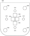
FIG. 43 shows an illustrative diagrammatic view of the bottom of the sensing unit of FIG. 42;
FIG. 44 shows an illustrative diagrammatic view of a system including the plurality of processing systems of FIG. 41;
FIG. 45 shows an illustrative diagrammatic view of a processing system including a programmable motion device positioned between an endless input conveyor and a reciprocating shuttle system in accordance with a further embodiment of the present invention;
fig. 46 shows an illustrative diagrammatic view of the handling system of fig. 45 with the reciprocating carriage moved along the rails between rows of output containers;
FIG. 47 shows an illustrative diagrammatic top view of the system of FIG. 45;
FIG. 48 shows an illustrative diagrammatic top view of the system of FIG. 48; and
FIG. 49 shows an illustrative diagrammatic view of a system according to a further embodiment including a plurality of processing stations as shown in FIG. 45.
The drawings are shown for illustrative purposes only.
Detailed Description
According to an embodiment, the present invention provides an object handling system that not only tracks objects (e.g., packages, envelopes, boxes, etc.), but also detects data about the objects at multiple points during processing, e.g., for pick verification and place verification. The detected data is checked against a set of reference pre-recorded data provided by a manifest (generated manually or automatically) or shipping label or the like. While the detected data may represent an estimated mass, weight, size, or volume, if a significant spread is found, the object may be held until the spread is resolved or rerouted to return to its original sender.
More specifically, the system can determine the identity of an object and access previously recorded data about the object. The previously recorded data may be provided by a manifest that provides for each object unique identification data, its mass or weight and its size or volume or density, as well as its delivery information, such as a delivery address or destination location. An identification tag (such as a barcode, QR code, or RFID tag) representing the identity data is applied to the object. The previously recorded data may also be provided by the sender, for example if the sender (or shipping company personnel) provides data on the mass or weight or size or volume of the object, density, etc. The shipping company personnel may then assign unique identity data to the object and apply an identifying indicia, such as a barcode, QR code, or RFID tag, representing the identity data. The destination information (such as an address or destination location) is then associated with the identity data of the object.
During processing, the system will determine the identity data of the object, and will then determine the mass, weight, size, volume, density, etc. of the object. The system then compares the determined data (e.g., mass, weight, size, or volume) to previously recorded data associated with the identity of the object. If a spread is found (e.g., over 2% -5% or 10%), the object will be internally rerouted to the holding station until the spread is resolved. The spread can be resolved by having the shipping network contact the sender via the shipping company, and having the sender's billing account information posted or debited the correct amount to make up the spread. If the spread is not resolved, the item may be returned to the sender, for example, by assigning the sender's address as the destination address associated with the item's identity data. In this case, the system may overwrite the pre-recorded data and assign the address of the sender as the destination address of the object. This will provide that the object is subsequently returned to the sender and may further include an explanation of the reason for the return, for example, by including a stamp or adhesive label reporting the determined mass, weight, size or volume.
According to some embodiments, the system may update the manifest if it is determined that the captured data more accurately reflects the characteristics of the object. For example, the system may record the known size and weight of the same object, and after multiple encounters with the object, the system may know that the sensed data is more accurate than the raw data in the manifest. For example, the system may employ learning in the sense of improving over time. The performance of the pick-up as the object, pick-up station and process parameters change may not be known a priori. Furthermore, objects that have not been picked up will be encountered periodically. However, it is possible that the new object is similar to the previously picked item and will have similar performance characteristics. For example, object X may be a shampoo in a twenty ounce bottle, and object Y may be a conditioner in a twenty ounce bottle. The shape of the bottles may be the same if dispensed by the same company. The system comprises the following processes: predicting future performance using observations of past performance of similar objects; and learning what characteristics of objects available to the system are reliable predictors of future performance. Learning is specifically a learning process that (a) extrapolates the performance of newly viewed objects, (b) continuously updates the data it learns to extrapolate in order to continuously improve performance.
Fig. 1 shows a system 10 according to an embodiment of the invention in which a sender 12 of a package, box or flat object fills out information about the package on a shipping form 14 and pays for the shipping via the sender's billing account 16. The information provided may include the mass and/or weight and/or size and/or volume of the object, etc., as well as the shipping address or destination location of the object. The package is then delivered to the shipping company 18 where it is received and tagged with an identifying indicia associated with the identity data of the object, which in turn is associated with the information provided by the sender (previously recorded data). The objects are then provided to the shipping network 20 for processing and distribution.
During this process, data about the package is acquired and recorded. If the data is incorrect (e.g., the package weight is much heavier or more voluminous than originally recorded), the sender will be notified (via the shipping company) and a further fee will be charged to the sender's billing account 16. In an embodiment, the package is not initially returned, but is provided to the delivery company 22 only when the account 16 is paid for a full payment (or credited if multiple payments) and the spread is subsidized. The package is then provided by the delivery company 22 to the recipient 24. If the spread is not subsidized (e.g., within 24 hours), the object will return to the sender's address (e.g., by assigning the sender's address to the shipping address).
The shipping network may include various distribution systems, such as distribution system 30 shown in FIG. 2. The delivery system 30 includes: a plurality of receiving stations 32 for receiving, for example, cargo containers from vehicles 34; a plurality of processing stations 36 capable of processing articles from the article container from the receiving station 32; a plurality of dispensing stations 38 may then provide the processed items in the cassette to a vehicle 40. The system may be controlled by one or more computer processing systems 42. Containers and boxes may be loaded into and removed from the vehicle by racks provided in the vehicle (e.g., a five-tiered set of three racks with rollers) and ramps from the vehicle to the receiving station and from the dispensing station 38 to the vehicle. The receiving station 32 and the dispensing station 38 also include a frame for receiving and supporting the containers and boxes, and a conveyor for moving the containers and boxes.
For example, fig. 3 shows a receiving station 32, which receiving station 32 includes a plurality of storage racks 44 (which may be provided as conveyors) for receiving a plurality of containers 46 containing objects to be processed. According to embodiments, the order of the containers on each conveyor may be known, and the contents of each container may be known. The receiving station 32 also includes a plurality of source conveyors 48, the source conveyors 48 providing selected containers to the processing station 34 via directional routing stations 52, the directional routing stations 52 routing containers between levels of the receiving station 36 (e.g., via lifts or ramps) so that containers may be provided to the processing conveyors 54. Thus, the source conveyors 48 may each serve more than one row of containers. For example, fig. 3 shows three source conveyors 48 that serve two sets of two rows of containers 46. Each set of rows of containers further includes a container displacement mechanism 50, the container displacement mechanism 50 being adapted to displace containers along a set of two rows of containers and to selectively displace containers onto adjacent source conveyors 48. In this way, the selected container is provided to the source conveyor 48 and the handling conveyor 54 via the directional routing station 52.
Referring to fig. 4, the processing station 36 includes a processing conveyor 54 and a programmable motion device 56. A container from the receiving station 32 is provided to the programmable movement apparatus 56 and the programmable movement apparatus 56 picks up the article from the container 46 and places the article into a first pallet 58, the first pallet 58 being mounted on an X-Y moveable stage 60 of the dispensing station 38. The order of each of the cassettes 64 on the rack or conveyor 65 is known. The first carriage 58 is then moved to the selected level and the second carriage 62 is positioned at the processing end of a set of rows of cassettes 64 (as shown, the cassettes are disposed on a conveyor 65). The destination station 38 also includes a plurality of output conveyors 66 for providing the boxes from the groups of two rows of boxes to a dispensing end 68 of the destination station 38, again by selectively displacing the boxes onto adjacent output conveyors 66 using a displacement mechanism (e.g., as discussed above with reference to fig. 3).
As shown in fig. 5, the programmable motion device 56 (e.g., a mechanical articulated arm) of the processing station 36 includes an end effector 70 (e.g., a vacuum cup, a grasping fixture, or other retention device) and a detection system 72. As further shown in fig. 6, the detection system may include a light 74 and one or more sensing units 76 (e.g., scanners or cameras) for detecting any identifying indicia (e.g., bar codes, QR codes, RFID, labels, etc.) on objects within the cargo box 46 and for directing the programmable motion device 56 to grasp objects within the cargo box with the end effector 70 (shown in fig. 5). With this system, the selected object is taken from the cargo box and transported via carrier 58 and then via carrier 62 to the desired box 64.
Such robotic pickers are used in many different types of applications for material handling. In one case, a robotic picker may be employed to pick individual objects from a collection of objects of the same type, and then transport the picked objects to a container or conveyor or other destination location. In some cases, robotic pick-up technology uses cameras and 3D scanners to sense and analyze the pick-up surface before it automatically selects the best position to pick up the object based on various criteria. In some cases, the robotic pick-up system may erroneously pick up two or more objects. This is an undesirable action as it can affect the accounting of the goods at the receiver and result in an erroneous count of the goods when tracking the number of objects remaining in inventory. It is desirable that the method senses whether the robot has picked up more than one object before the object is placed in the output container or conveyor, or after the object is placed, to prevent the transfer of multiple objects so that the inventory count can be updated. In certain further embodiments, likewise, such as when a robotic picker picks up from a handbag of a homogeneous object, the system may route the double pick to an output destination intended to receive two such objects when the double pick is detected.
The processing unit 36 also includes a capture system 78, the capture system 78 including scanning and receiving units 80, 82, and an edge detection unit 84 for capturing various characteristics of selected objects throughout the cargo box. Fig. 7A shows a view from the capture system 78 that may include a set of similar or dissimilar objects 90, 92, 94, 96, 98, according to an embodiment. The volume difference between the scans shown in fig. 7B and 7C is the estimated volume V of the removed object 9494. The volume is compared to the recorded data or recorded object data for the object identified by the identification mark provided by the detection system 72.
In particular, the contents of the cargo box are volumetrically scanned prior to removing the object from the cargo box 46, as shown in fig. 7B, and after removing the object 94 from the cargo box 46, the contents of the cargo box are volumetrically scanned, as shown in fig. 7C. The volume scan may be accomplished using a scanning and receiving unit 80, 82, which scanning and receiving unit 80, 82 sends and receives signals (e.g., infrared signals), and the processing system 42. According to an embodiment, the volume captured in fig. 7C is subtracted from the volume captured in fig. 7B, and the difference is evaluated as the estimated volume (V) of the removed object 9494). According toOther embodiments, a system that knows that an object 94 is to be acquired may capture volumetric data about the object 94 while the object 94 is still in the cargo box (as shown in fig. 7B). This may be done instead of or in addition to volume subtraction (between fig. 7B and 7C) as discussed above. According to a further embodiment, the scanning and receiving units 80, 82 may also be used to determine the density D of the object by knowing the mass and volume of the object94. The volumetric data may be obtained, for example, using any of a light detection and ranging (LIDAR) scanner, a pulse time-of-flight camera, a continuous wave time-of-flight camera, a structured light camera, or a passive stereo camera.
According to further embodiments, the system may additionally employ an edge detection sensor 84, the edge detection sensor 84 (again with the processing system 42) being used to detect an edge of any object in the cargo box, e.g., using data regarding any of intensity, shadow detection, or echo detection, etc., and may be used to determine any of a size, shape, and/or contour, e.g., as shown in fig. 7D. The system may also alter the illumination source position to assist in edge detection by, for example, cycling through the lamps 74 on the detection system 72 to highlight different edges, or use volume scanning or surface scanning to measure depth or surface discontinuities.
If the captured data (e.g., volume, density, size, etc.) is thus confirmed to be within a reliable tolerance range, the object will continue to be processed according to the manifest or shipping label. However, if not, the object may be directed to a holding location (e.g., a box designated as a holding location), and the object may remain in the holding location until the spread is resolved. For example, in certain embodiments, a weight measurement may be provided by a certified postal weight that will have a high reliability value and may be trusted for rerouting decisions of measurements near a tolerance threshold. On the other hand, for similar measurements close to the tolerance threshold using less reliable weight measurements (such as measurements made with a possibly unauthenticated postal calibrated machine), the object would have to be rerouted in order to verify the weight manually (and for appropriate further charges).
Referring again to fig. 5, the object is placed in the carriage 58 and delivered to any one of the carriages 62 by moving the carriage 58 along the X-Y movable stage 60 and then tilting the carriage 58 to drop the object into the carriage 62.
According to further embodiments, the system may estimate the volume of the object while the object is held by the end effector. While for some types of object handling systems (e.g., parcel sorting for shipment/mailing), volume may not be helpful (e.g., when shipping deformable plastic bags), in other systems, such as store replenishment or e-commerce applications, volume scanning would be very valuable. In particular, the system may estimate a volume of the picked-up object(s) while the picked-up object(s) are held by the end effector and compare the estimated volume to a known volume. To capture the estimated volume, in an embodiment, one or more sensing units (e.g., cameras or 3D scanners) are placed around the scanned volume to capture the volumetric data.
Referring to fig. 8 and 9, one or more sensing units 152, 154, 156, 158 (e.g., cameras or 3D scanners) are positioned around the scanning volume (including the end effector 70 and the object 94), each sensing unit being positioned opposite an illumination source 162, 164, 166, 168 and optionally including a diffusive screen 172, 174, 176, 178. As shown in fig. 9, the illumination source and sensing unit pairs (e.g., 158, 168, and 178) may be engaged simultaneously. With further reference to fig. 10 and 11, opposite each sensing element is an illumination source 162, 164, 166, 168 and optionally a diffuser screen 172, 174, 176, 178 in front of the respective illumination source.
As shown in fig. 11, perception data regarding the object 94 backlit by the illumination source (e.g., 168) and the diffuser (e.g., 178) will be captured by each perception unit (e.g., 158). FIG. 12 shows a view of the object 94 from the camera 158, the view showing the lower rear end; FIG. 13 shows a view of an object from camera 154, showing the lower front end; FIG. 14 shows a view of an object from camera 152, the view showing the lower left side; and figure 15 shows a view of the object from camera 156 showing the lower right side. According to various embodiments, three sensing units may be used, spaced 120 degrees apart, and according to further embodiments, fewer sensing units (e.g., one or two) may be used, and the object may be rotated between data acquisition captures.
The scan volume may be a volume above the region from which the object is picked up; or the scan volume may be strategically placed between the pick-up and placement locations to minimize travel time. Within the scan volume, the system takes a snapshot of the volume of the object held by the fixture. As discussed above, the volume may be estimated in a variety of ways depending on the sensor type.
For example, if the sensors are cameras, two or more cameras may be placed in a ring around the volume and facing slightly upwards towards a backlight screen (as discussed above), possibly in the cross-sectional shape of a circular ring, with the clip volume held between all cameras and a brightly lit white screen. The brightly lit screen backlight illuminates one or more held objects so that the interior volume appears black. Each sensing unit and associated illumination source may be activated in sequence such that no two illumination sources are turned on simultaneously. This allows easy segmentation of the retained volume in the image.
The object may be illuminated with ambient light, which may be provided as a specific wavelength not present in the room, which may be modulated and the detector may demodulate the received perception data such that only illumination from the associated source is provided. The black areas become truncated cones once projected back into space, and the object is known to be located in a stereoscopic viewing cone. Each camera generates a separate viewing cone with the property that the volume of the object is a subset of all viewing cones. The intersection of all the cones yields the upper boundary of the volume of the object(s). The addition of a camera improves the accuracy of the volume estimation. The fixture may be visible within the camera and, since its position and size are known, its volume may be subtracted from the viewing cone or volume estimate.
Conversely, if a 3D scanner that acquires a 3D image of the scanned volume is acquired, a volume estimate is acquired in a similar manner by fusing together the point clouds received from each sensor, but without the need to segment the image from the background using backlighting. Each 3D scanner returns a 3D image, returning depth for each pixel in the image.
According to other embodiments, a 3D scanner that acquires a 3D image of the scanned volume may be used, and then the volume estimate is obtained in a similar manner by fusing together the point clouds received from each sensor, but without the need to segment the image from the background using backlighting. Each 3D scanner returns a 3D image, returns depth for each pixel in the image, and again any of a light detection and ranging (LIDAR) scanner, a pulse time-of-flight camera, a continuous wave time-of-flight camera, a structured light camera, or a passive stereo camera, etc. may be used.
Thus, the system can compare the object volume with the difference in volume of the pick-up area before and after pick-up. Another approach is to analyze the pick or place volume or both the pick and place volumes using a 3D scanner and then estimate the amount of additional or subtracted volume observed in the sensing region. For example, first, a pickup area is scanned with a 3D scanner, which recovers a 3D point cloud of the area. Second, the robot picker picks up objects with the purpose of picking up a single object. Third, the pick-up area is rescanned and an estimate of how much volume is taken away from the pick-up area is formed. Fourth, as described above, using the volume estimate, it is decided whether the volume difference is deemed to exceed a predetermined threshold of the volume of a single number of objects, based on one or more defined thresholds.
According to a further embodiment, the system may scan the pick-up volume before and after pick-up and compare the estimated volumes. In this case, the volume of the pick or place area may be estimated in the following manner. Assume that the 3D scanner views the pickup area generally downward, or at a small angle. The 3D scanner provides an image of the area and, for each pixel in the image, a range of geometry in the pixel direction. A point cloud may be formed using such an array of range measurements. The point cloud represents a point in three-dimensional space that is estimated to be on the top surface of the pickface, which is the topmost surface of the object to be picked. The regions of the pickface may be discretized into a grid of vertical columns, and for each vertical column, an estimate of the height of the geometry within the vertical column may be obtained by taking the maximum, average, median, minimum, or some other robust statistic of the heights of the points located within the column. The volume of the pick-up area is then the sum of the values of the height values estimated for each vertical column.
For various reasons, such as resolution, reflection or transparency, some vertical columns may not have any cloud points, in which case the resolution may be adaptively changed so that the vertical columns are wide enough that none have cloud points. Various types of statistics may be obtained to determine the boundaries of the volume, such as using the variance of the heights of the points within a column (variance) to obtain the overall variance of the pick-up region volume. In this way, an estimate of the differential volume can be obtained in the pick-up area, the volume of which would be reduced by a single pick-up if a single object was indeed picked up; or, if a single object is indeed placed, the volume of the area will increase for a single pick; alternatively, the difference volumes picked and placed may be estimated and combined to prevent noise and errors in the estimation.
For example, fig. 16 shows a structured light 3D scanner 182 projecting a grid 188 onto a field of view. The 3D scanner 182 may be used in the system 180 shown in fig. 17A with one, two, or three other 3D scanners (two more shown at 184, 186). The 3D scanner is directed to a common volume in which the object 94 is positioned while attached to the end effector 70. With three such 3D scanners, the scanners can be positioned 120 degrees apart (90 degrees apart if four are used; and opposite each other if only two are used). Fig. 17B-17D show a system 189 having upper sensing units 183a, 185a, 187a located above the object 94 held by the end effector 70 and lower sensing units 183B, 185B, 187B located below the object 94 held by the end effector 70 to provide even further perspective and greater reliability of the volume estimation provided to the system. As shown in fig. 17C, the upper and lower sensing units are disposed at different angles to capture more data points about the held item. Fig. 17D shows the vertical separation and different viewing angles of the upper sensing unit 183a and the lower sensing unit 187 b. Although system 189 is shown with 6 sensing units, a single sensing unit, or a single upper sensing unit and a single lower sensing unit, may be used if rotated around the object to view all sides.
Referring to fig. 18 and 19, each 3D scanner (e.g., 182) captures 3D data about an object. When the grid is displayed on an object, the lines will become distorted when viewed from different perspectives. The warped view may then be used for geometric reconstruction to determine the surface profile of the object. Once the volume of the end effector is identified during reconstruction, the volume may be removed from the captured data. The displayed grid or other line pattern may be provided as coherent laser light or incoherent light, and have a static or dynamic pattern.
In either or any of the methods of obtaining a volume estimate, the volume estimate is then compared to a known volume of the object. Since the sensor data may be noisy and since the various algorithms used to estimate the volume may result in small errors, depending on the application, the threshold used to decide whether more than one pick occurred is adjusted to balance the number of false positives (a pick is estimated to contain more than one object but only one is actually held) and false negatives (a pick is estimated to contain a single object but in fact contains more than one object). The adjusted threshold may also depend on the object in question, and each object may have its own threshold. If it is determined that the threshold has been exceeded, the objects may be placed back in the area where they were picked so that the robot may again attempt to pick a single object.
According to further embodiments, the system may detect multiple pickups by automatically sensing leaks from flow or pressure data. Referring to fig. 20, the system may use an end effector 170, the end effector 170 including a sensor 160 (such as a flow sensor or pressure sensor). For example, the system may detect a much larger flow rate (or increase in vacuum pressure) than predicted for the object 94, possibly because two objects (92, 94) are grabbed, causing a large amount of air to be drawn into the end effector 170 from between the two objects.
Thus, the system can detect multiple pickups by automatically sensing leaks from flow or pressure data. Another approach is to calculate statistical information from observations of flow and pressure while holding an object to compare it to statistical information collected when the same object was previously collected. In a further embodiment, the system may calculate a variance and other statistics from the time series data of flow and/or pressure while holding the object to compare with statistics from previous picks of the same or similar objects. In a further embodiment, the system may also compare the obtained values and if the difference exceeds a certain threshold, the system may specify that it is an instance of picking up more than one object. In further embodiments, the system may employ a linear classifier, support vector machine, or other machine learning based classifier to distinguish between single or multiple pickups using flow or pressure data. Additionally, the system may combine any subset of the above methods. The system may also use a performance model of any of the above, where the system knows the probability of single or multiple picks given the detected output, and may then combine any or all of the above methods.
In some applications, such as picking from a homogenous bag of objects, the system may identify an activation sequence (e.g., from a manifest) that requires two such objects (and not yet having a total number of such objects, requiring at least two or more). The system may then route the identified dual pickups to the identified locations, noting that two such objects have been delivered to the identified locations. However, such systems must maintain active monitoring of grasping, and can learn over time which types of objects may be more likely to result in multiple picks, and which such multiple picks may be reliably delivered by the end effector, and further may be further processed together in the processing system. In particular, if a shuttle tray is used, the system must know that two such objects will be loaded into the tray at the same time. If the shuttle carriage includes weight sensing, the presence of two such object pickups will be confirmed, as discussed herein with reference to FIGS. 21-32. Since the system can learn not only the type of object that can be handled as multi-pick, the system can also learn the type of grab that can be handled reliably as multi-pick (e.g., double pick).
According to a further embodiment, the system may compare the weight held or transferred to the weight of the known object. In such systems, the method is to measure the weight of the picked-up object and compare the measured weight to an a priori known weight of the object. Weighing of the objects may be accomplished in any of a number of ways, including at the clamp, by a force or load sensing mechanism in the clamp, continuously weighing by gauges at the pick or place area, or at an underlying pick area container or conveyor, to measure weight changes before and after pick or place, or on an auxiliary transport mechanism (such as a shuttle that transports individual picked objects to other locations), or on a temporary weighing mechanism within the workspace of the robotic pick unit, where the robot places one or more objects on a holding pallet, weighs the objects on the holding pallet and the robot re-picks the objects.
Fig. 21-25 illustrate a cradle 100 (e.g., any of the cradles 58, 62) according to an embodiment of the present invention, the cradle 100 including a generally V-shaped body 103 for receiving an object, and a pair of beam-disrupting emitters and receivers 102, 104 (e.g., infrared emitters and receivers) of the body 103 for detecting when an object enters or exits. Referring to fig. 21, the carrier also includes a support frame 106 for supporting the body 103, and an actuating means for moving the carrier along the track and selectively tilting the carrier to drop the contents of the carrier into another carrier, cassette or other container. The drive may be any of a pneumatic or electrical control system 108, and the communication to and from the carriage may be wireless communication from an electronic processing system 110 (as shown in fig. 22).
The cradle also includes a pair of load cells 112, 114 coupled to the frame 106, and the cradle body 103 is mounted to (and suspended by) the load cells. By positioning the load cell on the body of the carrier close to the object(s) held therein, a highly reliable weight measurement can be obtained. Once an object is detected, for example by the beam break transmitter and receiver pair 102, 104, the system will determine the weight of the object. According to an embodiment, the system compares the weight values (W) of the two load units1,W2) The weight of the body 100 is added and subtracted. In this way, it is also possible to take the weight of the object and check it with the manifest or shipping information (within a tolerance range of, for example, 2% to 5%). According to other embodiments, the load cell itself may register a change, indicating that the carrier has received or ejected an object.
The carrier body 103 is adapted to be rotatable about an axis 117 (to empty its contents), and the carrier body 103 is attached to the top 119 of the load cell 112, 114 above the axis of rotation 117. Fig. 23 shows a top view of the carriage, and fig. 24 shows an end view of the carriage on the side opposite the actuation system 108. Fig. 25 shows the tray tilted (rotated about axis 117) to empty its contents, and this movement can continue until stop plate 115 contacts stop 116 (as shown in fig. 21).
Weight detection is very important for many industrial tasks. If the object in the pallet has a weight that is significantly different from the weight in the manifest or shipping label, the object may be held until resolved as discussed above (e.g., for additional cost). According to other embodiments, the pallet may be used for transporting a plurality of objects as objects of the same weight. Where the same weight is known, the number of objects in the carrier can be determined by dividing the total weight measured by the weight of the known object.
Fig. 26 and 27 (in a view similar to fig. 21 and 22) show a pallet 100 'according to another embodiment of the invention similar to the embodiment shown in fig. 21-25, the pallet 100' having a body 103 ', the body 103' comprising a higher back wall 101 against which an object can be redirected into the generally V-shaped body of the pallet. In particular, particularly with respect to the cradle 62, the first cradle 58 may drop an object into the cradle having a body 100 'such that the first cradle 58 is located on the side of the cradle 100' of fig. 26 and 27 opposite the higher rear wall 101.
The carriage 100' is similarly mounted on the frame 106 via load cells 112, 114, and its movement along the track and tilting is controlled by an actuation system 108. Communication and electronic control is provided by an electronic processing and communication system 110 (shown in fig. 27). Again, the load cells 112, 114 may be used to determine the weight of the contents of the carrier, as discussed above with reference to fig. 21-25. For example, once the beam break transmitter and receiver pair 102, 104 detects an object, the system according to an embodiment will measure the weight value (W) of both load cells1,W2) Add and subtract the weight of the body 103'. According to other embodiments, the load cell itself may register a change, indicating that the carrier has received or ejected an object.
Fig. 28-30 show a cradle 120 according to another embodiment of the invention, the cradle 120 comprising a main body 122 and a V-shaped plate 124 mounted on the main body 122 by a load cell 126 (the V-shaped plate has been removed as shown in fig. 29). Load cells 126 may each acquire weight data through the other four load cells, e.g., W as shown in FIG. 263、W4、W5、W6And W7、W8、W9、W10. Fig. 30 shows a bracket 120 including body walls not shown in fig. 29 and also removed from fig. 28. The remainder of the carriage 120 includes a support frame for movement along the track, as well as an actuation system and electronic processing and communication system, as discussed above. Again, as discussed above, the load cell 126 may be used to determine the weight of the contents of the cradle. For example, upon detecting (e.g., by beam-disrupting transmitter and receiver pairs as discussed above) that an object has entered the cradle 120, a system according to embodiments will be eight negativesWeight value (W) of load cell3、-W10) Add and subtract the weight of V-shaped plate 124.
Fig. 31 and 32 show a bracket 140 according to another embodiment of the invention, the bracket 140 comprising a main body 142 and a mounting bracket 144 mounted to a support bracket 146 by a load cell 148. Load cells 148 may each acquire weight-bearing data, e.g., W as shown in FIG. 3111、W12. Fig. 32 shows an enlarged view of the load cell 148 coupled between the bracket mounting bracket 144 and the support frame 146. The remainder of the carriage 120 includes the remainder of the support frame for movement along the rails, as well as the actuation system and electronic processing and communication system for selectively rotating the carriage body about the axis 145, as discussed above. Again, as discussed above, the load cell 148 may be used to determine the weight of the contents of the cradle. For example, upon detecting (e.g., by beam-disrupting transmitter and receiver pairs as discussed above) that an object has entered the carriage 140, the system according to embodiments will measure the weight values (W) of the two load cells11、-W12) The combined weight of the main body 142 and the two bracket mounting brackets 144 is added and subtracted.
FIG. 33 shows a processing station 36 'according to another embodiment of the present invention, the processing station 36' including a drop-sensing system 200 by which an object (e.g., 194) may be dropped into a first carriage 58 mounted on an X-Y moveable stage 60. The object (194) is identified by a perception device (e.g., a camera or scanner) that detects any identifying indicia (e.g., barcode, QR code, RFID, etc.) on the object. With further reference to fig. 34, the object then falls through the drop scanner 200 via the guide 202 and into the first carriage 58 via the chute 204. As described above, the carriage 58 includes an object detection system (such as a load cell or beam break detection system) that detects when the carriage 58 receives an object, and the carriage 58 then moves to the appropriate row and carriage 62 based on the detected markers.
The processing unit 36 also includes a capture system 78, the capture system 78 including scanning and receiving units 80, 82, and an edge detection unit 84 (as discussed above with reference to fig. 6) for capturing various characteristics of the selected object or the entire container. Fig. 35A shows a view from a volume detection system 78, which volume detection system 78 may include a set of similar or dissimilar objects 190, 192, 194, 196, 198 according to an embodiment. The contents of the cargo box are volume scanned by the scanning and receiving units 80, 82 prior to removal of the objects from the cargo box 46, as shown in fig. 35B, and after removal of the objects 194 from the cargo box 46, as shown in fig. 35C.
According to an embodiment, the volume captured in fig. 35C is subtracted from the volume captured in fig. 35B, and the difference is evaluated as the volume (V) of the removed object 194194). According to other embodiments, a system that knows that an object 194 is to be captured may capture volumetric data about the object 194 while the object 194 is still in the cargo box (as shown in fig. 35B). This may be done instead of or in addition to volumetric subtraction (between fig. 35B and fig. 35C) as discussed above. According to a further embodiment, the scanning and receiving units 80, 82 may also be used to determine the density D of the object by knowing the mass and volume of the object194。
The volume difference between the scans shown in FIG. 35B and FIG. 35C is the volume V of the removed object 194194. The volume is compared to the recorded data or recorded data about the object identified by the identification mark provided by the perception system 200. If the volume is confirmed to be within tolerance, the object continues to be handled as a manifest or shipping label. However, if the volume is not within tolerance, the object may be directed to a holding location (e.g., a box designated as the holding location) where the object may remain until the spread is resolved. As discussed above with reference again to fig. 5, the object is dropped into the carriage 58 and delivered to any one of the carriages 62 by moving the carriage 58 along the X-Y movable stage 60 and then tilting the carriage 58 to drop the object into the carriage 58.
In accordance with further embodiments and with reference to fig. 35D, the system may additionally employ an edge detection sensor 84, the edge detection sensor 84 (again with the processing system 42) being used to detect an edge of any object in the cargo box, for example using an image of any of intensity data, shadow detection, or echo detection, etc. This information may be used to determine or verify any of the identity, position, orientation, size, shape, and/or contour of the object. For example, edge detection may be performed before or after the volume scan, and thereafter a volume may be calculated for each identified object within the container.
Fig. 36 and 37 show the fall detection system 200 in more detail. In particular, the fall detection system 200 includes a structure 242 having a top opening 244 and a bottom opening 246, and may be covered by a closure material 248 (e.g., a colored covering such as orange plastic) to protect humans from potentially dangerous glare within the secondary detection system. The structure 242 includes a plurality of rows of sources (e.g., illumination sources such as LEDs) 250 and a plurality of image sensing units (e.g., cameras) 252. The sources 250 are arranged in rows and each point to the center of the opening. Sensing units 252 are also generally pointed at the openings, although some are pointed horizontally, others are pointed upward, and some are pointed downward. The system 228 also includes an entrance source (e.g., infrared source) 254 and an entrance detector (e.g., infrared beam break detector 256) for detecting when an object enters the perception system 228. Thus, the LEDs and camera surround the interior of the structure 242, and the sensing unit is positioned to view the interior via a window that may include a glass or plastic cover (e.g., 258). The perception unit may include a camera (e.g., 2D or 3D) or a scanner (e.g., a light reflection or radio frequency scanner), and the processing system 20 may include associated software to process the perception data. The scanner looks for various codes, such as a mark (e.g., a bar code, radio frequency tag, Stock Keeping Unit (SKU), Universal Product Code (UPC), digital identification DW code (Digimarc DWCode), etc.).
Fig. 38-40 show a representative set of two rows of output boxes 64 adjacent to the output conveyor 66 of the destination station 38. In particular, as discussed above and as shown in fig. 38, each carriage 62 receives an object 160 from the first carriage 58, and each carriage 62 is reciprocally movable between output cassettes 64. As further shown in fig. 39, each carriage 62 moves along a track 170 and can be actuated to drop an object 160 into a desired output cassette 64 by tilting as shown.
The output box may be disposed in a conveyor (e.g., rollers or belts) and may be biased (e.g., by gravity) to push all destination containers toward one end 680, as shown. Referring to fig. 40, when an output box 64 is selected for removal (e.g., because the container is full or otherwise ready for further processing), the system will push the completed box onto an output conveyor 66 for taking to a further processing or shipping station. This may be accomplished, for example, using the displacement mechanism 50 as discussed above. The conveyor 66 may be biased (e.g., by gravity or power) such that any containers on the conveyor are brought to an output position at a second end 682 opposite the first end 680. The destination container may be provided as a box or container or any other type of device that can receive and hold objects, including a box pallet assembly.
After displacing the cassettes onto the conveyor, each of the output cassettes may be pushed together and the system will register the change in position of any of the moved cassettes. In this way, new empty boxes can be added at the end, and the system will record the correct location and identified processing details for each of the destination boxes.
Each of the above-described detection systems for detecting or estimating any of weight, size, mass, volume, density, etc. may be used with various object handling systems. For example, fig. 41 shows a processing system 302 that includes a programmable motion system 300. The programmable motion system 302 includes an articulated arm 304 and an end effector 306. The system 300 may retrieve objects from containers 310 disposed on a conveyor 312 and place the retrieved objects in reciprocating carriages 314, the reciprocating carriages 314 traveling along tracks 316 between rows of cassettes 320. The completed cassette may be pushed onto an output conveyor 322, which output conveyor 322 directs the completed cassette to a collected output conveyor 324.
The system 302 includes a sensing unit 308, and with further reference to fig. 42 and 43, the sensing unit 308 combines the functions of the detection system 72 and the capture system 78 discussed above, and includes a light 374 and sensing unit 376, scanning and receiving units 380, 382, and an edge detection unit 384. Each sensing unit 308 may thus capture the identification marker and provide a volumetric 3D scan as discussed above.
The cradle 314 may be any of the cradles discussed above with reference to fig. 21-32, and thus the estimated weight or mass of the object(s) in the cradle may be determined. The system may also check all of the detected/estimated data against the manifest or original shipping record and process the object as discussed above, selecting the appropriate box 320, and placing the object into that box 320 in response to the data. As shown in fig. 44, the system can be scaled so that multiple programmable motion systems 302 can process objects into multiple carriages 314 and output boxes 320.
Further, fig. 45 shows a processing system 400 including a programmable motion system 402. Programmable motion system 402 includes an articulated arm 404 and an end effector 406. Fig. 46 shows a top view of the system of fig. 45. The system 400 may retrieve objects from containers 410 disposed on a conveyor 412 and place the retrieved objects in reciprocating carriages 414, which reciprocating carriages 414 travel along tracks 416 between rows of cassettes 420, as shown in fig. 47 (showing a view similar to fig. 45) and fig. 48 (showing a top view similar to fig. 46). The containers 410 may be provided by a conveyor 424 and a circulating conveyor 430, the conveyor 424 and circulating conveyor 430 using one or more diverters 432 to provide the containers 410. The completed cassette may be pushed onto an output conveyor 422, which output conveyor 422 directs the completed cassette to a collected output conveyor 424.
The system 402 includes a sensing unit 408 identical to the sensing unit 308 discussed above that combines the functions of the detection system 72 and the capture system 78, and includes a light and sensing unit, a scanning and receiving unit, and an edge detection unit. Each sensing unit 408 may thus capture the identification marker and provide a volumetric 3D scan as discussed above.
The carriage 414 may be any of the carriages discussed above with reference to fig. 21-32, and thus the estimated weight or mass of the object(s) in the carriage may be determined. The system may also check all detected/estimated data against the manifest or original shipping record and process the object as discussed above, selecting the appropriate box 420 into which the object is placed in response to the data 420. As shown in fig. 49, the system can be scaled so that multiple programmable motion systems 402 can process objects into multiple carriages 414 and output boxes 420.
Those skilled in the art will appreciate that numerous modifications and variations may be made to the above disclosed embodiments without departing from the spirit and scope of the invention.