CN113038354A - Head tracking for parametric binaural output systems and methods - Google Patents
Head tracking for parametric binaural output systems and methods Download PDFInfo
- Publication number
- CN113038354A CN113038354A CN202110229741.7A CN202110229741A CN113038354A CN 113038354 A CN113038354 A CN 113038354A CN 202110229741 A CN202110229741 A CN 202110229741A CN 113038354 A CN113038354 A CN 113038354A
- Authority
- CN
- China
- Prior art keywords
- audio
- dominant
- component
- representation
- estimate
- Prior art date
- Legal status (The legal status is an assumption and is not a legal conclusion. Google has not performed a legal analysis and makes no representation as to the accuracy of the status listed.)
- Granted
Links
Images


Classifications
-
- H—ELECTRICITY
- H04—ELECTRIC COMMUNICATION TECHNIQUE
- H04S—STEREOPHONIC SYSTEMS
- H04S3/00—Systems employing more than two channels, e.g. quadraphonic
-
- G—PHYSICS
- G10—MUSICAL INSTRUMENTS; ACOUSTICS
- G10L—SPEECH ANALYSIS TECHNIQUES OR SPEECH SYNTHESIS; SPEECH RECOGNITION; SPEECH OR VOICE PROCESSING TECHNIQUES; SPEECH OR AUDIO CODING OR DECODING
- G10L19/00—Speech or audio signals analysis-synthesis techniques for redundancy reduction, e.g. in vocoders; Coding or decoding of speech or audio signals, using source filter models or psychoacoustic analysis
- G10L19/008—Multichannel audio signal coding or decoding using interchannel correlation to reduce redundancy, e.g. joint-stereo, intensity-coding or matrixing
-
- H—ELECTRICITY
- H04—ELECTRIC COMMUNICATION TECHNIQUE
- H04R—LOUDSPEAKERS, MICROPHONES, GRAMOPHONE PICK-UPS OR LIKE ACOUSTIC ELECTROMECHANICAL TRANSDUCERS; DEAF-AID SETS; PUBLIC ADDRESS SYSTEMS
- H04R5/00—Stereophonic arrangements
- H04R5/033—Headphones for stereophonic communication
-
- H—ELECTRICITY
- H04—ELECTRIC COMMUNICATION TECHNIQUE
- H04S—STEREOPHONIC SYSTEMS
- H04S3/00—Systems employing more than two channels, e.g. quadraphonic
- H04S3/002—Non-adaptive circuits, e.g. manually adjustable or static, for enhancing the sound image or the spatial distribution
- H04S3/004—For headphones
-
- H—ELECTRICITY
- H04—ELECTRIC COMMUNICATION TECHNIQUE
- H04S—STEREOPHONIC SYSTEMS
- H04S3/00—Systems employing more than two channels, e.g. quadraphonic
- H04S3/008—Systems employing more than two channels, e.g. quadraphonic in which the audio signals are in digital form, i.e. employing more than two discrete digital channels
-
- H—ELECTRICITY
- H04—ELECTRIC COMMUNICATION TECHNIQUE
- H04S—STEREOPHONIC SYSTEMS
- H04S7/00—Indicating arrangements; Control arrangements, e.g. balance control
- H04S7/30—Control circuits for electronic adaptation of the sound field
- H04S7/302—Electronic adaptation of stereophonic sound system to listener position or orientation
- H04S7/303—Tracking of listener position or orientation
- H04S7/304—For headphones
-
- H—ELECTRICITY
- H04—ELECTRIC COMMUNICATION TECHNIQUE
- H04S—STEREOPHONIC SYSTEMS
- H04S2400/00—Details of stereophonic systems covered by H04S but not provided for in its groups
- H04S2400/01—Multi-channel, i.e. more than two input channels, sound reproduction with two speakers wherein the multi-channel information is substantially preserved
-
- H—ELECTRICITY
- H04—ELECTRIC COMMUNICATION TECHNIQUE
- H04S—STEREOPHONIC SYSTEMS
- H04S2400/00—Details of stereophonic systems covered by H04S but not provided for in its groups
- H04S2400/11—Positioning of individual sound objects, e.g. moving airplane, within a sound field
-
- H—ELECTRICITY
- H04—ELECTRIC COMMUNICATION TECHNIQUE
- H04S—STEREOPHONIC SYSTEMS
- H04S2420/00—Techniques used stereophonic systems covered by H04S but not provided for in its groups
- H04S2420/01—Enhancing the perception of the sound image or of the spatial distribution using head related transfer functions [HRTF's] or equivalents thereof, e.g. interaural time difference [ITD] or interaural level difference [ILD]
-
- H—ELECTRICITY
- H04—ELECTRIC COMMUNICATION TECHNIQUE
- H04S—STEREOPHONIC SYSTEMS
- H04S2420/00—Techniques used stereophonic systems covered by H04S but not provided for in its groups
- H04S2420/03—Application of parametric coding in stereophonic audio systems
Landscapes
- Engineering & Computer Science (AREA)
- Physics & Mathematics (AREA)
- Acoustics & Sound (AREA)
- Signal Processing (AREA)
- Multimedia (AREA)
- Computational Linguistics (AREA)
- Audiology, Speech & Language Pathology (AREA)
- Human Computer Interaction (AREA)
- Health & Medical Sciences (AREA)
- Mathematical Physics (AREA)
- Stereophonic System (AREA)
- Golf Clubs (AREA)
- Measurement Of The Respiration, Hearing Ability, Form, And Blood Characteristics Of Living Organisms (AREA)
- Massaging Devices (AREA)
- Stereophonic Arrangements (AREA)
Abstract
The present disclosure relates to head tracking for parametric binaural output systems and methods. A method of encoding channel-based or object-based input audio for playback, the method comprising the steps of: (a) first rendering channel-based or object-based input audio into an initial output representation; (b) determining an estimate of a dominant audio component from the channel-based or object-based input audio, and determining a series of dominant audio component weighting factors for mapping the initial output representation to the dominant audio component; (c) determining an estimate of a dominant audio component direction or position; and (d) encoding the initial output representation, the dominant audio component weighting factor, the dominant audio component direction or position as an encoded signal for playback.
Description
This application is a divisional patent application of the invention patent application having application number 201680075037.8, filed 2016, 11/17 entitled "head tracking for parametric binaural output system and method".
Technical Field
The present invention provides systems and methods that optionally utilize an improved form of parametric binaural output at head tracking.
Reference to the literature
Gundry, k., "a New Matrix Decoder for Surround Sound (a New Matrix Decoder for Surround Sound)," AES 19th International conf., "Schloss Elmau, germany, 2001.
Vinton, m., McGrath, d., Robinson, c., Brown, p., "Next generation surround decoding and upmixing for consumer and professional applications", AES 57th International Conf, Hollywood, CA, USA, 2015.
Wightman, F.L. and Kistler, D.J, (1989), "Headphone simulation of free-field listening," I.Stimulus synthesis, "J.Acoust. Soc.am.85, 858-867.
ISO/IEC 14496-3: 2009-information technology-encoding of audiovisual objects-part 3: audio (Information technology-Coding of Audio-visual objects-Part 3: Audio), 2009.
Mania, Katerina et al, "Perceptual sensitivity to head tracking delays in virtual environments with varying degrees of scene complexity" Proceedings of the 1st Symposium on Applied performance in graphics and visualization. ACM 2004.
Allison, r.s., Harris, l.r., Jenkin, m., jasioboedzka, u, and Zacher, j.e. (2001, March.) Tolerance of time delay In Virtual environments (Tolerance of temporal delay In visual environments) In visual Reality, 2001. proceedings.ieee (pp.247-254).
Van de Par, Steven and Armin Kohlrausch, "Sensitivity to auditory-visual dyssynchrony and jitter to jitter in auditory-visual timing," Electronic imaging, International Society for Optics and Photonics, 2000.
Background
Any discussion of the background art throughout the specification should in no way be considered as an admission that such art is widely known or forms part of common general knowledge in the field.
Content creation, encoding, distribution and reproduction of audio content has traditionally been channel-based. That is, a particular target playback system is contemplated for the content of the entire content ecosystem. Examples of such target playback systems are mono, stereo, 5.1, 7.1, 7.1.4, etc.
If the content is to be reproduced on a playback system different from the intended playback system, then downmix or upmix may be applied. For example, 5.1 content can be reproduced on a stereo playback system by employing certain known downmix equations. Another example is playback of stereo content on a 7.1 speaker setup, which 7.1 speaker setup may comprise a so-called upmix process, which may or may not be guided by information present in the stereo signal, such as the stereo signal used by a so-called matrix encoder, such as Dolby Pro Logic. To direct the upmix process, information about the original position of the signal before the downmix can be implicitly signaled (signal) by including a specific phase relation in the downmix equation, or in other words by applying a complex-valued downmix equation. A well-known example of such a downmix method using complex-valued downmix coefficients for content with loudspeakers placed in two dimensions is LtRt (Vinton et al 2015).
The resulting (stereo) downmix signal may be reproduced on a stereo loudspeaker system or may be upmixed to a loudspeaker setup with surround loudspeakers and/or height loudspeakers. The expected positioning of the signal may be derived from the inter-channel phase relation by an upmixer. For example, in an LtRt stereo representation, a signal that is out of phase (e.g., has an inter-channel waveform normalization cross-correlation coefficient close to-1) should ideally be reproduced by one or more surround speakers, while a positive correlation coefficient (close to +1) indicates that the signal should be reproduced by speakers in front of the listener.
Various upmix algorithms and strategies have been developed which differ in their strategy of recreating a multi-channel signal from a stereo downmix. In a relatively simple upmixer, the normalized cross-correlation coefficients of the stereo waveform signal are tracked over time, and the signal(s) are directed (steer) to the front or rear speakers according to the values of the normalized cross-correlation coefficients. This method works well for relatively simple content where only one auditory object is present at the same time. Higher level upmixers are based on statistical information derived from specific frequency regions to control the signal flow from stereo input to multi-channel output (Gundry 2001, Vinton et al 2015). In particular, a signal model based on a pilot or dominant component and a stereo (diffuse) residual signal may be employed in each time/frequency tile (tile). In addition to estimating the dominant component and the residual signal, a direction (in azimuth, possibly supplemented by elevation) angle is also estimated, the dominant component signal then being directed to one or more loudspeakers to reconstruct the (estimated) position during playback.
The use of matrix encoders and decoders/upmixers is not limited to channel-based content. Recent developments in the audio industry are based on audio objects, rather than channels, in which one or more objects contain an audio signal and associated metadata that, among other things, indicates the expected location of the audio signal as a function of time. For such object-based audio content, a matrix encoder may also be used, as outlined in the Vinton et al 2015 document. In such a system, the object signal is downmixed into a stereo signal representation having downmix coefficients dependent on the object position metadata.
The upmix reproduction of matrix-encoded content is not necessarily limited to playback on loudspeakers. The pilot component or a representation of the pilot component containing the dominant component signal and the (expected) position makes it possible to reproduce on headphones by means of convolution with the head-related impulse response (HRIR) (wihtman et al, 1989). A simple schematic of a system implementing the method is shown in fig. 1. The input signal 2 in matrix coded format is first analyzed 3 to determine the dominant component direction and magnitude. The dominant component signal is convolved 4, 5 by means of a pair of HRIRs derived from a look-up table 6 based on the dominant component direction to compute an output signal for headphone playback 7 such that the playback signal is perceived as coming from the direction determined by the dominant component analysis stage 3. This scheme can be applied on a wideband signal as well as on individual subbands and can be supplemented with various ways of dedicated processing of the residual (or diffuse) signal.
The use of matrix encoders is well suited for distribution to and reproduction on AV receivers, but can be problematic for mobile applications requiring low transmission data rates and low power consumption.
Whether channel-based content or object-based content is used, matrix encoders and decoders rely on the fairly accurate inter-channel phase relationship of the signal distributed from the matrix encoder to the decoder. In other words, the distribution format should be largely waveform-preserving. Such dependency on waveform preservation can be problematic in bitrate constrained conditions, where the audio codec employs a parametric approach rather than waveform coding tools to achieve better audio quality. Examples of such parametric tools, which are generally known for waveform non-retention, are commonly referred to as spectral band replication, parametric stereo, spatial audio coding, etc., as implemented in MPEG-4 audio codecs (ISO/IEC 14496-3: 2009).
As outlined in the previous section, the upmixer contains the analysis and guidance (or HRIR convolution) of the signal. For powered devices, such as AV receivers, this generally does not cause problems, but for battery operated devices, such as mobile phones and tablets, the computational complexity and corresponding memory requirements associated with these processes are generally undesirable because their impact on battery life is negative.
The foregoing analysis also typically introduces additional audio delay. Such audio latency is undesirable because (1) it requires video delay to maintain audio-video edge (lip) synchronization, which requires a large amount of memory and processing power, and (2) in the case of head tracking, it may cause asynchrony/latency between head movement and audio rendering.
The matrix-coded downmix may also not be acoustically optimal over stereo loudspeakers or headphones, since strongly out-of-phase signal components may be present.
Disclosure of Invention
It is an object of the invention to provide an improved form of parameterized binaural output.
According to a first aspect of the present invention, there is provided a method of encoding channel-based or object-based input audio for playback, the method comprising the steps of: (a) first rendering channel-based or object-based input audio into an initial output representation (e.g., an initial output representation); (b) determining an estimate of a dominant audio component from the channel-based or object-based input audio, and determining a series of dominant audio component weighting factors for mapping the initial output representation to the dominant audio component; (c) determining an estimate of a dominant audio component direction or position; and (d) encoding the initial output representation, the dominant audio component weighting factor, the dominant audio component direction or position as an encoded signal for playback. Providing a series of dominant audio component weighting factors for mapping the initial output representation to the dominant audio component may enable an estimate of the dominant component to be determined using the dominant audio component weighting factors and the initial output representation.
In some embodiments, the method further comprises determining an estimate of a residual mix, the residual mix being a rendering of the initial output representation minus the dominant audio component or an estimate thereof. The method may further comprise: an anechoic binaural mix of channel-based or object-based input audio is generated, and an estimate of a residual mix is determined, where the estimate of the residual mix may be the anechoic binaural mix minus a rendering of the dominant audio component or an estimate thereof. Furthermore, the method may comprise determining a series of residual matrix coefficients for mapping the initial output representation to an estimate of the residual mix.
The initial output representation may comprise an earphone or loudspeaker representation. The channel-based or object-based input audio may be sliced in time and frequency, and the encoding steps may be repeated for a series of time steps and a series of frequency bands. The initial output representation may comprise a stereo speaker mix.
According to a further aspect of the present invention, there is provided a method of decoding an encoded audio signal, the encoded audio signal comprising: a first (e.g., initial) output representation (e.g., first/initial output representation), a dominant audio component direction, and a dominant audio component weighting factor; the method comprises the following steps: (a) determining an estimated dominant component using the dominant audio component weighting factor and the initial output representation; (b) rendering the estimated dominant component by binauralizing at a spatial location relative to an intended listener according to a dominant audio component direction to form a rendered binauralized estimated dominant component; (c) representing a reconstructed residual component estimate from a first (e.g., initial) output; and (d) combining the rendered binauralized estimated dominant and residual component estimates to form an output spatialized audio encoded signal.
The encoded audio signal further may comprise a series of residual matrix coefficients representing the residual audio signal, and step (c) further may comprise: (c1) the residual matrix coefficients are applied to a first (e.g., initial) output representation to reconstruct a residual component estimate.
In some embodiments, the residual component estimate may be reconstructed by subtracting the dominant component of the rendered binauralized estimate from the first (e.g., initial) output representation. Step (b) may comprise making an initial rotation of the estimated dominant component in dependence on an input head tracking signal indicative of the head orientation of the intended listener.
According to a further aspect of the present invention, there is provided a method for decoding and reproducing an audio stream for a listener using headphones, the method comprising: (a) receiving a data stream containing a first audio representation and additional audio transform data; (b) receiving head orientation data representing an orientation of a listener; (c) creating one or more auxiliary signals based on the first audio representation and the received transform data; (d) creating a second audio representation comprising a combination of the first audio representation and the ancillary signal(s), in which second audio representation one or more of the ancillary signal(s) has been modified in response to the head orientation data; and (e) outputting the second audio representation as an output audio stream.
In some embodiments, the modification of the secondary signal may further comprise a simulation of an acoustic path from the sound source location to the listener's ear. The transform data may comprise matrixed coefficients and at least one of: sound source location or sound source direction. The transform process may be applied according to time or frequency. The auxiliary signal may represent at least one dominant component. The sound source position or direction may be received as part of the transformation data and may be rotated in response to the head orientation data. In some embodiments, the maximum amount of rotation is limited to a value less than 360 degrees in azimuth or elevation. The second representation may be obtained from the first representation by matrixing in a transform domain or a filter bank domain. The transform data further may comprise additional matrixing coefficients, and step (d) further may comprise modifying the first audio representation in response to the additional matrixing coefficients prior to combining the first audio representation and the auxiliary audio signal(s).
Drawings
Embodiments of the invention will now be described, by way of example only, with reference to the accompanying drawings, in which:
fig. 1 schematically shows a headphone decoder for matrix encoded content;
fig. 2 schematically shows an encoder according to an embodiment;
FIG. 3 is a schematic block diagram of a decoder;
FIG. 4 is a detailed visualization of an encoder; and
figure 5 shows one form of decoder in more detail.
Detailed Description
Embodiments provide a system and method of representing object-based or channel-based audio content that is (1) compatible with stereo playback, (2) enables binaural playback including head tracking, (3) has low decoder complexity, and (4) does not rely on matrix coding, but is still compatible with matrix coding.
This is achieved by an encoder-side analysis combining one or more dominant components (or dominant objects or combinations thereof) comprising weights combined with additional parameters to predict these dominant components from the downmix, the weights minimizing the error between a binaural rendering based only on the dominant components or the dominant components and a desired binaural representation of the entire content.
In an embodiment, the analysis of the dominant component (or components) is provided in the encoder, not in the decoder/renderer. The audio stream is then supplemented with metadata indicating the direction of the dominant component and information on how the dominant component(s) may be obtained from the associated downmix signal.
Fig. 2 shows one form of the encoder 20 of the preferred embodiment. The object-based or channel-based content 21 is analyzed 23 to determine the dominant component(s). This analysis may occur in terms of time and frequency (assuming that the audio content is broken down into time slices and frequency sub-slices). The result of this processing is a dominant component signal 26 (or dominant component signals) and associated position(s) or direction information(s) 25. Subsequently, weights are estimated 24 and output 27 so that the dominant component signal(s) can be reconstructed from the transmitted downmix. The downmix generator 22 does not necessarily have to comply with the LtRt downmix rule but may be a standard itu (lore) downmix using non-negative real-valued downmix coefficients. Finally, the output downmix signal 29, weights 27 and position data 25 are packed by the audio encoder 28 and are ready for distribution.
Turning now to fig. 3, a corresponding decoder 30 of the preferred embodiment is shown. The audio decoder reconstructs the downmix signal. The signal is input 31 and unpacked (unpackack) by the audio decoder 32 into the downmix signal, the direction and the weights of the dominant component. The dominant component estimation weights are then used to reconstruct (34) the guidance component(s) that are rendered 36 using the transmitted position or orientation data. The position data may optionally be modified 33 according to head rotation or translation information 38. In addition, the reconstructed dominant component(s) may be subtracted (35) from the downmix. Optionally, there is a subtraction of the dominant component(s) within the downmix path, but alternatively, as described below, this subtraction may also occur at the encoder.
To improve the removal or cancellation of the reconstructed dominant component in subtractor 35, the dominant component output may first be rendered using the transmitted position or direction data prior to subtraction. This optional rendering stage 39 is shown in fig. 3.
Returning now to describing the encoder in greater detail initially, fig. 4 illustrates one form of an encoder 40 for processing object-based (e.g., Dolby Atmos) audio content. The audio objects are initially stored as Atmos objects 41 and are first divided into time slices and frequency slices by using a hybrid complex-valued quadrature mirror filter (HCQMF) bank 42. When in useWhen we omit the corresponding time index and frequency index, the input object signal can be xi[n]Represents; the corresponding position within the current frame is represented by a unit vector Given, index i refers to the object number and index n refers to time (e.g., subband sample index). Input object signal xi[n]Are examples of channel-based or object-based input audio.
Using a complex-valued scalar Hl,i、Hr,i(e.g., single tap HRTF 48) to create 43 a binaural mix Y (Y) of the silenced sub-bandsl,yr) Complex-valued scalar Hl,i、Hr,iThe representation corresponds to a position The sub-band representation of HRIR of (a):


alternatively, the binaural mix Y (Y) may be created by using a head-related impulse response (HRIR)l,yr). In addition, an amplitude translation gain factor g is usedl,i、gr,iTo create 44 a stereo downmix zl、zr(an initial output representation is illustratively implemented):


the dominant component may be estimated in the following manner Direction vector (illustratively implementing the dominant audio component direction or position): the
 dominant component 45 is calculated by first calculating a weighted sum of the unit direction vectors for each object:

wherein, is the signal xi[n]Energy of (2):

wherein, ()*Is a complex conjugate operator.
The dominant/pilot signal d [ n ] (illustratively implementing the dominant audio component) is then given by the following equation:

wherein, is to generate a vector with a unit
 The distance between increases and decreases as a function of gain. For example, to create a virtual microphone with a directional pattern based on higher order spherical harmonics, one implementation would correspond to:

wherein, denotes a unit direction vector in a two-or three-dimensional coordinate system, (-) denotes a dot product operator of two vectors, and a, b, and c denote exemplary parameters (e.g., a ═ b ═ 0.5; c ═ 1).
Calculating 46 a weight or prediction coefficient wl,d、wr,dAnd use these weights or prediction coefficients wl,d、wr,dTo calculate 47 an estimated pilot signal

Wherein the weight wl,d、wr,dMinimizing the signal z in the downmixl、zrGiven case d [ n ]]And mean square error between. Weight wl,d、wr,dIs used to represent the initial output (e.g., z)l、zr) Is mapped to the dominant audio component (e.g.,
 ) Examples of dominant audio component weighting factors. A known method of deriving these weights is by applying a Minimum Mean Square Error (MMSE) predictor:
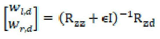
wherein R isabIs the covariance matrix between the signals for signal a and signal b, and e is the regularization parameter.
We can then mix y from anechoic binaural soundl、yrSubtracting 49 the dominant component signal So as to use the dominant component signal
 Direction/position of
 Associated HRTF (HRIR) Hl,D、
H r,D50 to create residual binaural mixes


Finally, another set of prediction coefficients or weights w is estimated 51i,jThese prediction coefficients or weights wi,jSo that a minimum mean square error estimate can be used to derive z from the stereo mixl、zrReconstructing residual binaural mix
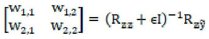
Wherein R isabIs the covariance matrix between the signals representing a and b, and e is the regularization parameter. Prediction coefficient or weight wi,jIs used to represent the initial output (e.g., z)l、zr) Mapping to residual binaural mix Of estimated residual matrix coefficientsExamples are given. Additional level constraints may be imposed on the above expression to overcome any prediction penalty. The encoder outputs the following information:
stereo audio mixing zl、zr(an initial output representation is illustratively implemented);
estimating coefficients w of the dominant componentl,d、wr,d(illustratively implementing dominant audio component weighting factors);
position or direction of dominant component
And optionally, a residual weight wi,j(residual matrix coefficients are implemented exemplarily).
Although the above description relates to rendering based on a single dominant component, in some embodiments the encoder may be adapted to detect a plurality of dominant components, determine a weight and direction for each of the plurality of dominant components, render each of the plurality of dominant components and subtract each of the plurality of dominant components from the anechoic binaural mix Y, and then determine a residual weight after each of the plurality of dominant components has been subtracted from the anechoic binaural mix Y.
Decoder/renderer
Fig. 5 shows one form of the decoder/renderer 60 in more detail. The decoder/renderer 60 applies the input information z intended to be unpacked neverl、zr;wl,d、wr,d; wi,jReconstructing binaural mix yl、yrFor output to the
 listener 71. Here, the stereo mix zl、zrIs an example of a first audio representation, a prediction coefficient or weight wi,jAnd/or dominant component signals Direction/position of
 Is an example of additional audio transform data.
First, the stereo downmix is divided into time/frequency tiles using a suitable filter bank or transform 61, such as an HCQMF analysis bank 61. Other transforms such as discrete fourier transforms, (modified) cosine or sine transforms, time domain filter banks or wavelet transforms may equally be applied. Then, the prediction coefficient weight w is usedl,d、wr,dTo calculate 63 an estimated dominant component signal

Estimated dominant component signal Is an example of an auxiliary signal. Thus, this step may be said to correspond to the creation of one or more auxiliary signals based on said first audio representation and the received transformation data.
The dominant component signal is then rendered 65 and based on the transmitted position/direction data Modified 68 with
 HRTF 69, the transmitted position/orientation data Possibly modified (rotated) based on information obtained from the
 head tracker 62. Finally, the total anechoic binaural output includes and is based on the prediction coefficient weights wi,jReconstructed residual error of The dominant component signal of summation 66:
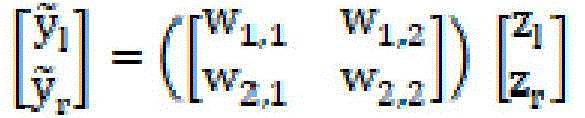

the total silenced binaural output is an example of the second audio representation. Thus, this step may be said to correspond to creating a second audio representation comprising a combination of said first audio representation and said auxiliary signal(s), in which second audio representation one or more of said auxiliary signal(s) has been modified in response to said head orientation data.
It should further be noted that if information on more than one dominant signal is received, each dominant signal may be rendered and added to the reconstructed residual signal.
Outputting a signal as long as head rotation or translation is not applied Should be very close (in terms of root mean square error) to the reference binaural signal yl、yrAs long as

Key Properties
As can be observed from the above equation formulation, an efficient operation for constructing an anechoic binaural representation from a stereo representation comprises a 2x2 matrix 70 in which the matrix coefficients depend on the transmitted information wl,d、wr,d; wi,jAnd head tracker rotation and/or translation. This means that the complexity of the processing is relatively low, since the analysis of the dominant componentIs applied in the encoder rather than in the decoder.
If the dominant component is not estimated (e.g., w)l,d、wr,d0), the described solution is equivalent to a parametric binaural approach.
In the case where it is desired to exclude certain objects from head rotation/head tracking, these objects may be excluded from (1) dominant component direction analysis and (2) dominant component signal prediction. As a result, these objects will pass through the coefficient wi,jFrom stereo to binaural and is therefore not affected by any head rotation or translation.
In a similar approach, objects can be set to a "pass through" mode, which means that in a binaural representation, they will be amplitude translated instead of HRIR convolved. This can be done by simply aligning the coefficients Using amplitude panning gains instead of single-tap HRTFs, or using any other suitable binaural processing.
Extension
Embodiments are not limited to the use of stereo downmix, as other channel counts may be employed.
The decoder 60 described with reference to fig. 5 has an output signal containing the direction of the dominant component of the rendering, plus the matrix coefficients wi,jThe matrixed input signals. The latter coefficients may be derived in various ways, for example:
1. can be assisted in the encoder by means of signals To determine the coefficient wi,j. In other words, in this implementation, the coefficient wi,jAiming at faithfully reconstructing a binaural signal yl、yrThese binaural signals would have been obtained when the original input objects/channels were rendered binaural; in other words, the coefficient wi,jIs content driven.
2. The coefficient w can bei,jFrom the encoder to the decoder to represent the HRTF for a fixed spatial position (e.g., a spatial position at +/-45 degrees in azimuth). In other words, the residual signal is processed to simulate reproduction on two virtual loudspeakers at certain locations. When these coefficients representing the HRTFs are sent from the encoder to the decoder, the location of the virtual speakers may change over time and frequency. If the method is used to represent the residual signal by using a static virtual loudspeaker, the coefficient wi,jNeed not be sent from the encoder to the decoder and may instead be hardwired in the decoder. A variant of this approach would include a limited set of static positions available in the decoder and their corresponding coefficients wi,jAnd the choice of which static position to use for processing the residual signal is indicated from the encoder to the decoder.
Signal More than 2 signals may be reconstructed via a so-called upmixer by means of statistical analysis of these signals at the decoder, followed by binaural rendering of the resulting upmixed signals.
The described method can also be applied in systems where the transmitted signal Z is a binaural signal. In this particular case, the decoder 60 of fig. 5 remains intact, while the block 44 labeled "generate stereo (LoRo) mix" in fig. 4 should be replaced by the same "generate anechoic binaural mix" 43 (fig. 4) as the block that produces the signal pair Y. In addition, other forms of mixes may be generated as desired.
The method can be extended to a method of reconstructing one or more FDN input signals from a transmitted stereo mix containing specific objects or channel subsets.
The method can be extended to predict a plurality of dominant components from the transmitted stereo mix and render these dominant components at the decoder side. There is basically no restriction that only one dominant component is predicted for each time/frequency slice. In particular, the number of dominant components may be different in each time/frequency tile.
Explanation of the invention
Reference throughout this specification to "one embodiment," "some embodiments," or "an embodiment" means that a particular feature, structure, or characteristic described in connection with the embodiment is included in at least one embodiment of the present invention. Thus, appearances of the phrases "in one embodiment," "in some embodiments," or "in an embodiment" in various places throughout this specification are not necessarily all referring to the same embodiment, but may. Furthermore, the particular features, structures, or characteristics may be combined in any suitable manner, as would be apparent to one of ordinary skill in the art from this disclosure, in one or more embodiments.
As used herein, unless otherwise specified the use of the ordinal adjectives "first", "second", "third", etc., to describe a common object, merely indicate that different instances of like objects are being referred to, and are not intended to imply that the objects so described must be in a given sequence, either temporally, spatially, in ranking, or in any other manner.
In the appended claims and this description, any of the terms "comprising," "including," or "it includes" is an open term that means including at least the following elements/features, but not excluding others. Thus, the term "comprising" when used in a claim should not be interpreted as limiting the means or elements or steps listed thereafter. For example, the scope of the expression "a device comprising a and B" should not be limited to devices consisting of only elements a and B. As used herein, any of the terms "comprising" or "includes" or "it includes" is also an open term that also means including at least the elements/features that follow the term, but not excluding other elements/features. Thus, including is synonymous with and means comprising.
As used herein, the term "exemplary" is used in a sense to provide an example, as opposed to indicating quality. That is, an "exemplary embodiment" is an embodiment provided as an example, as opposed to an embodiment that must be of an exemplary quality.
It should be appreciated that in the foregoing description of exemplary embodiments of the invention, various features of the invention are sometimes grouped together in a single embodiment, figure, or description thereof for the purpose of streamlining the disclosure and aiding in the understanding of one or more of the various inventive aspects. This method of disclosure, however, is not to be interpreted as reflecting an intention that the claimed invention requires more features than are expressly recited in each claim. Rather, as the following claims reflect, inventive aspects lie in less than all features of a single foregoing disclosed embodiment. Thus, the following claims are hereby expressly incorporated into this detailed description, with each claim standing on its own as a separate embodiment of this invention.
Furthermore, although some embodiments described herein include some, but not other, features included in other embodiments, combinations of features of different embodiments are intended to be within the scope of the invention, and form different embodiments as would be understood by those of skill in the art. For example, in the appended claims, any of the claimed embodiments may be used in any combination.
Furthermore, some of the embodiments are described herein as a method or combination of elements of a method that can be implemented by a processor of a computer system, or by other means of implementing functionality. Thus, a processor with the instructions required to implement such a method or an element of a method forms a means for implementing the method or the element of the method. Furthermore, the elements of an apparatus embodiment described herein are examples of means for performing the functions performed by the elements for the purposes of implementing the invention.
In the description provided herein, numerous specific details are set forth. However, it is understood that embodiments of the invention may be practiced without these specific details. In other instances, well-known methods, structures and techniques have not been shown in detail in order not to obscure an understanding of this description.
Similarly, it is to be noticed that the term 'coupled', when used in the claims, should not be interpreted as being restricted to direct connections only. The terms "coupled" and "connected," along with their derivatives, may be used. It should be understood that these terms are not intended as synonyms for each other. Thus, the scope of the expression "device a coupled to device B" should not be limited to devices or systems in which the output of device a is directly connected to the input of device B. It means that there exists a path between the output of a and the input of B, which may be a path including other devices or means. "coupled" may mean that two or more elements are in direct physical or electrical contact, or that two or more elements are not in direct contact with each other, but yet still co-operate or interact with each other.
Accordingly, while embodiments of the invention have been described, those skilled in the art will recognize that other and further modifications may be made thereto without departing from the spirit of the invention, and it is intended to claim all such changes and modifications as fall within the scope of the invention. For example, any of the formulas given above are merely representative of processes that may be used. Functionality may be added or deleted from the block diagrams and operations may be exchanged between functional blocks. Steps may be added or deleted to methods described within the scope of the present invention.
Aspects of the invention may be appreciated from the following Enumerated Example Embodiments (EEES):
EEE 1. a method of encoding channel-based or object-based input audio for playback, the method comprising the steps of:
(a) first rendering channel-based or object-based input audio into an initial output representation;
(b) determining an estimate of a dominant audio component from the channel-based or object-based input audio, and determining a series of dominant audio component weighting factors for mapping the initial output representation to the dominant audio component;
(c) determining an estimate of a dominant audio component direction or position; and is
(d) The initial output representation, the dominant audio component weighting factor, the dominant audio component direction or position are encoded into an encoded signal for playback.
EEE 3. the method according to EEE 1, further comprising: an anechoic binaural mix of channel-based or object-based input audio is generated, and an estimate of a residual mix is determined, wherein the estimate of the residual mix is the anechoic binaural mix minus the dominant audio component or an estimated rendering of the dominant audio component.
EEE 4. the method according to EEE 2 or 3, further comprising determining a series of residual matrix coefficients for mapping the initial output representation to an estimate of the residual mix.
EEE 6. the method according to any of the preceding EEEs, wherein channel-based or object-based input audio is sliced in time and frequency, and the encoding step is repeated for a series of time steps and a series of frequency bands.
EEE 8. a method of decoding an encoded audio signal, the encoded audio signal comprising:
-a first output representation;
-a dominant audio component direction and a dominant audio component weighting factor;
the method comprises the following steps:
(a) determining an estimated dominant component using the dominant audio component weighting factor and the initial output representation;
(b) rendering the estimated dominant component by binauralizing at a spatial location relative to an intended listener according to a dominant audio component direction to form a rendered binauralized estimated dominant component;
(c) representing a reconstructed residual component estimate from the first output; and is
(d) The rendered binauralized estimated dominant and residual component estimates are combined to form an output spatialized audio encoded signal.
EEE 9. the method according to EEE 8, wherein the encoded audio signal further comprises a series of residual matrix coefficients representing the residual audio signal, and said step (c) further comprises:
(c1) the residual matrix coefficients are applied to the first output representation to reconstruct a residual component estimate.
EEE 10. the method according to EEE 8, wherein the residual component estimate is reconstructed by subtracting the dominant component of the rendered binauralized estimate from the first output representation.
EEE 11. the method according to EEE 8, wherein said step (b) comprises performing an initial rotation of the estimated dominant component in dependence on an input head tracking signal indicative of the head orientation of the intended listener.
EEE 12. a method for decoding and reproducing an audio stream for a listener using headphones, the method comprising:
(a) receiving a data stream containing a first audio representation and additional audio transform data;
(b) receiving head orientation data representing an orientation of a listener;
(c) creating one or more auxiliary signals based on the first audio representation and the received transform data;
(d) creating a second audio representation comprising a combination of the first audio representation and the auxiliary signal(s), in which second audio representation one or more of the auxiliary signal(s) has been modified in response to the head orientation data; and is
(e) The second audio representation is output as an output audio stream.
EEE 13. the method according to EEE 12, wherein the modification of the auxiliary signal comprises a simulation of an acoustic path from the sound source position to the ear of the listener.
EEE 14. the method according to EEE 12 or 13, wherein the transform data comprises matrixing coefficients and at least one of: sound source location or sound source direction.
EEE 15. the method according to any of the EEEs 12 to 14, wherein the transformation process is applied in time or frequency.
EEE 16. the method according to any of EEEs 12 to 15, wherein the auxiliary signal represents at least one dominant component.
EEE 17. the method according to any of EEEs 12 to 16, wherein the sound source position or direction received as part of the transformed data is rotated in response to the head orientation data.
EEE 18. the method according to EEE 17, wherein the maximum rotation is limited to a value less than 360 degrees in azimuth or elevation.
EEE 19. the method according to any of EEEs 12 to 18, wherein the second representation is obtained from the first representation by matrixing in a transform domain or a filter bank domain.
Claims (22)
1. A system configured to encode channel-based or object-based input audio (21) for playback, comprising:
one or more processors; and
a computer-readable medium storing instructions that, when executed by the one or more processors, cause the one or more processors to perform operations comprising:
rendering channel-based or object-based input audio (21) into an initial output representation;
determining (23) an estimate of a dominant audio component (26) from channel-based or object-based input audio (21), the determining comprising:
determining (24) a series of dominant audio component weighting factors (27) for mapping the initial output representation to the dominant audio component, and
determining an estimate of the dominant audio component (26) based on the dominant audio component weighting factor (27) and the initial output representation;
determining an estimate of a dominant audio component direction or position (25); and is
Encoding the at least one of the dominant audio component direction or position, the initial output representation, and the dominant audio component weighting factor (27) into an encoded signal for playback.
2. The system of claim 1, the operations further comprising determining an estimate of a residual mix that is a rendering of the initial output representation minus the dominant audio component or the estimate of the dominant audio component.
3. The system of claim 1, the operations further comprising generating an anechoic binaural mix of channel-based or object-based input audio, and determining an estimate of a residual mix, wherein the estimate of the residual mix is the anechoic binaural mix minus a rendering of a dominant audio component or an estimate of the dominant audio component.
4. The system of claim 2 or 3, the operations further comprising determining a series of residual matrix coefficients for mapping an initial output representation to an estimate of a residual mix.
5. The system of any preceding claim, wherein the initial output representation comprises an earpiece or loudspeaker representation.
6. The system of any preceding claim, wherein the channel-based or object-based input audio is sliced in time and frequency and the encoding step is repeated for a series of time steps and a series of frequency bands.
7. The system of any preceding claim, wherein the initial output representation comprises a stereo speaker mix.
8. A system configured to decode an audio signal, comprising:
one or more processors; and
a computer-readable medium storing instructions that, when executed by the one or more processors, cause the one or more processors to perform operations comprising:
receiving an encoded audio signal, the encoded audio signal comprising:
an initial output representation;
a dominant audio component direction; and
a dominant audio component weighting factor;
determining an estimated dominant component based on the dominant audio component weighting factor and the initial output representation;
forming a dominant component of the rendered binauralized estimate, including a dominant component estimated by binauralized rendering at a spatial location relative to an intended listener according to a dominant audio component direction;
representing a reconstructed residual component estimate from the initial output; and is
An output spatialized audio signal is generated by combining the rendered binauralized estimated dominant and residual component estimates.
9. The system of claim 8, wherein the encoded audio signal further comprises a series of residual matrix coefficients representing a residual audio signal, and reconstructing the residual component estimate further comprises:
the residual matrix coefficients are applied to an initial output representation to reconstruct a residual component estimate.
10. The system according to claim 8 or 9, wherein the residual component estimate is reconstructed by subtracting the rendered binauralized estimated dominant component from the initial output representation.
11. The system of any of claims 8-10, wherein forming the rendered binauralized estimated dominant component includes performing an initial rotation of the estimated dominant component in accordance with an input head tracking signal indicative of an intended listener's head position.
12. The system of any of claims 8 through 11, wherein the residual component estimate is reconstructed by subtracting the rendered binauralized estimated dominant component from the initial output representation, and wherein forming the rendered binauralized estimated dominant component comprises performing an initial rotation of the estimated dominant component in accordance with an input head tracking signal indicative of a head position of an intended listener.
13. A computer-readable storage medium having instructions stored thereon, which, when executed by one or more processors, cause one or more devices to perform operations comprising:
rendering channel-based or object-based input audio (21) into an initial output representation;
determining (23) an estimate of a dominant audio component (26) from channel-based or object-based input audio (21), the determining comprising:
determining (24) a series of dominant audio component weighting factors (27) for mapping the initial output representation to the dominant audio component, and
determining an estimate of the dominant audio component (26) based on the dominant audio component weighting factor (27) and the initial output representation;
determining an estimate of a dominant audio component direction or position (25); and is
Encoding the at least one of the dominant audio component direction or position, the initial output representation, and the dominant audio component weighting factor (27) into an encoded signal for playback.
14. A method for decoding and reproducing audio streams for a listener using headphones, the method comprising:
receiving a data stream containing a first audio representation and additional audio transform data;
receiving head orientation data representing an orientation of a listener;
creating one or more auxiliary signals based on the first audio representation and the received transform data;
creating a second audio representation comprising a combination of the first audio representation and the auxiliary signals, in which second audio representation one or more of the auxiliary signals have been modified in response to the head orientation data; and is
The second audio representation is output as an output audio stream.
15. The method of claim 14, wherein the modification of the secondary signal comprises a simulation of an acoustic path from the sound source location to the listener's ear.
16. The method of claim 14 or 15, wherein the transform data comprises matrixed coefficients and at least one of: sound source location or sound source direction.
17. The method of any of claims 14 to 16, wherein the transform processing is applied in terms of time or frequency.
18. The method according to any of claims 14-17, wherein the auxiliary signal represents at least one dominant component.
19. The method of any of claims 14-18, wherein a sound source position or direction received as part of the transformation data is rotated in response to the head orientation data.
20. The method of claim 19, wherein the maximum amount of rotation is limited to a value less than 360 degrees in azimuth or elevation.
21. The method according to any of claims 14-19, wherein the second representation is obtained from the first representation by matrixing in a transform domain or a filter bank domain.
22. The method of any of claims 14-21, wherein transforming the data further comprises additional matrixing coefficients, and creating the second audio representation further comprises modifying the first audio representation in response to the additional matrixing coefficients prior to combining the first audio representation and the auxiliary audio signal.
Applications Claiming Priority (6)
| Application Number | Priority Date | Filing Date | Title |
|---|---|---|---|
| US201562256462P | 2015-11-17 | 2015-11-17 | |
| US62/256,462 | 2015-11-17 | ||
| EP15199854.9 | 2015-12-14 | ||
| EP15199854 | 2015-12-14 | ||
| PCT/US2016/062497 WO2017087650A1 (en) | 2015-11-17 | 2016-11-17 | Headtracking for parametric binaural output system and method |
| CN201680075037.8A CN108476366B (en) | 2015-11-17 | 2016-11-17 | Head tracking for parametric binaural output systems and methods |
Related Parent Applications (1)
| Application Number | Title | Priority Date | Filing Date |
|---|---|---|---|
| CN201680075037.8A Division CN108476366B (en) | 2015-11-17 | 2016-11-17 | Head tracking for parametric binaural output systems and methods |
Publications (2)
| Publication Number | Publication Date |
|---|---|
| CN113038354A true CN113038354A (en) | 2021-06-25 |
| CN113038354B CN113038354B (en) | 2025-09-30 |
Family
ID=55027285
Family Applications (3)
| Application Number | Title | Priority Date | Filing Date |
|---|---|---|---|
| CN201680075037.8A Active CN108476366B (en) | 2015-11-17 | 2016-11-17 | Head tracking for parametric binaural output systems and methods |
| CN202110229741.7A Active CN113038354B (en) | 2015-11-17 | 2016-11-17 | Head tracking for parameterized binaural output systems and methods |
| CN202511343987.1A Pending CN121151789A (en) | 2015-11-17 | 2016-11-17 | Head tracking for parameterizing binaural output systems and methods |
Family Applications Before (1)
| Application Number | Title | Priority Date | Filing Date |
|---|---|---|---|
| CN201680075037.8A Active CN108476366B (en) | 2015-11-17 | 2016-11-17 | Head tracking for parametric binaural output systems and methods |
Family Applications After (1)
| Application Number | Title | Priority Date | Filing Date |
|---|---|---|---|
| CN202511343987.1A Pending CN121151789A (en) | 2015-11-17 | 2016-11-17 | Head tracking for parameterizing binaural output systems and methods |
Country Status (15)
| Country | Link |
|---|---|
| US (2) | US10362431B2 (en) |
| EP (4) | EP3378239B1 (en) |
| JP (1) | JP6740347B2 (en) |
| KR (3) | KR20250107956A (en) |
| CN (3) | CN108476366B (en) |
| AU (2) | AU2016355673B2 (en) |
| BR (2) | BR112018010073B1 (en) |
| CA (2) | CA3005113C (en) |
| CL (1) | CL2018001287A1 (en) |
| ES (2) | ES2950001T3 (en) |
| IL (1) | IL259348B (en) |
| MY (1) | MY188581A (en) |
| SG (1) | SG11201803909TA (en) |
| UA (1) | UA125582C2 (en) |
| WO (1) | WO2017087650A1 (en) |
Families Citing this family (25)
| Publication number | Priority date | Publication date | Assignee | Title |
|---|---|---|---|---|
| EA202090186A3 (en) | 2015-10-09 | 2020-12-30 | Долби Интернешнл Аб | AUDIO ENCODING AND DECODING USING REPRESENTATION CONVERSION PARAMETERS |
| ES2950001T3 (en) * | 2015-11-17 | 2023-10-04 | Dolby Int Ab | Head tracking for parametric binaural output system |
| WO2018152004A1 (en) * | 2017-02-15 | 2018-08-23 | Pcms Holdings, Inc. | Contextual filtering for immersive audio |
| CN111052770B (en) * | 2017-09-29 | 2021-12-03 | 苹果公司 | Method and system for spatial audio down-mixing |
| US11004457B2 (en) * | 2017-10-18 | 2021-05-11 | Htc Corporation | Sound reproducing method, apparatus and non-transitory computer readable storage medium thereof |
| CN113207078B (en) | 2017-10-30 | 2022-11-22 | 杜比实验室特许公司 | Virtual rendering of object-based audio on arbitrary sets of speakers |
| EP3777246B1 (en) * | 2018-04-09 | 2022-06-22 | Dolby International AB | Methods, apparatus and systems for three degrees of freedom (3dof+) extension of mpeg-h 3d audio |
| US11032662B2 (en) | 2018-05-30 | 2021-06-08 | Qualcomm Incorporated | Adjusting audio characteristics for augmented reality |
| TWI683582B (en) * | 2018-09-06 | 2020-01-21 | 宏碁股份有限公司 | Sound effect controlling method and sound outputting device with dynamic gain |
| JP7321272B2 (en) | 2018-12-21 | 2023-08-04 | フラウンホファー ゲセルシャフト ツール フェールデルンク ダー アンゲヴァンテン フォルシュンク エー.ファオ. | SOUND REPRODUCTION/SIMULATION SYSTEM AND METHOD FOR SIMULATING SOUND REPRODUCTION |
| CN111615044B (en) * | 2019-02-25 | 2021-09-14 | 宏碁股份有限公司 | Energy distribution correction method and system for sound signal |
| CN119653301A (en) | 2019-06-12 | 2025-03-18 | 谷歌有限责任公司 | 3D audio source spatialization |
| US11076257B1 (en) * | 2019-06-14 | 2021-07-27 | EmbodyVR, Inc. | Converting ambisonic audio to binaural audio |
| GB2586214A (en) * | 2019-07-31 | 2021-02-17 | Nokia Technologies Oy | Quantization of spatial audio direction parameters |
| GB2586586A (en) * | 2019-08-16 | 2021-03-03 | Nokia Technologies Oy | Quantization of spatial audio direction parameters |
| US12183351B2 (en) | 2019-09-23 | 2024-12-31 | Dolby Laboratories Licensing Corporation | Audio encoding/decoding with transform parameters |
| TW202533213A (en) | 2019-10-30 | 2025-08-16 | 美商杜拜研究特許公司 | Multichannel audio encode and decode using directional metadata |
| CN115989682B (en) * | 2020-08-27 | 2026-01-02 | 苹果公司 | Stereo-based Immersive Coding (STIC) |
| US11750745B2 (en) * | 2020-11-18 | 2023-09-05 | Kelly Properties, Llc | Processing and distribution of audio signals in a multi-party conferencing environment |
| CA3206707A1 (en) * | 2021-01-29 | 2022-08-04 | Adriana Vasilache | Determination of spatial audio parameter encoding and associated decoding |
| WO2022173986A1 (en) | 2021-02-11 | 2022-08-18 | Nuance Communications, Inc. | Multi-channel speech compression system and method |
| CN113035209B (en) * | 2021-02-25 | 2023-07-04 | 北京达佳互联信息技术有限公司 | Three-dimensional audio acquisition method and three-dimensional audio acquisition device |
| US12250534B2 (en) * | 2022-11-11 | 2025-03-11 | Bang & Olufsen A/S | Adaptive sound scene rotation |
| WO2026006293A1 (en) * | 2024-06-24 | 2026-01-02 | Dolby Laboratories Licensing Corporation | Transmission of interactive audio content |
| CN118660266A (en) * | 2024-07-05 | 2024-09-17 | 北京朗德科技有限公司 | A spatial sound field reconstruction method and system |
Citations (6)
| Publication number | Priority date | Publication date | Assignee | Title |
|---|---|---|---|---|
| CN1295778A (en) * | 1998-04-07 | 2001-05-16 | 雷·M·杜比 | Low bit rate spatial coding method and system |
| CN101843114A (en) * | 2007-11-01 | 2010-09-22 | 诺基亚公司 | Focusing on a portion of an audio scene for an audio signal |
| CN102696244A (en) * | 2009-10-05 | 2012-09-26 | 哈曼国际工业有限公司 | Multi-channel audio system with audio channel compensation |
| US20130272527A1 (en) * | 2011-01-05 | 2013-10-17 | Koninklijke Philips Electronics N.V. | Audio system and method of operation therefor |
| WO2014191798A1 (en) * | 2013-05-31 | 2014-12-04 | Nokia Corporation | An audio scene apparatus |
| CN108476366A (en) * | 2015-11-17 | 2018-08-31 | 杜比实验室特许公司 | Head tracking for parametric binaural output systems and methods |
Family Cites Families (29)
| Publication number | Priority date | Publication date | Assignee | Title |
|---|---|---|---|---|
| AUPO316296A0 (en) * | 1996-10-23 | 1996-11-14 | Lake Dsp Pty Limited | Dithered binaural system |
| KR20010030608A (en) | 1997-09-16 | 2001-04-16 | 레이크 테크놀로지 리미티드 | Utilisation of filtering effects in stereo headphone devices to enhance spatialization of source around a listener |
| JPH11220797A (en) * | 1998-02-03 | 1999-08-10 | Sony Corp | Headphone equipment |
| JP4088725B2 (en) * | 1998-03-30 | 2008-05-21 | ソニー株式会社 | Audio playback device |
| US6839438B1 (en) | 1999-08-31 | 2005-01-04 | Creative Technology, Ltd | Positional audio rendering |
| DE60036958T2 (en) | 1999-09-29 | 2008-08-14 | 1...Ltd. | METHOD AND DEVICE FOR ORIENTING SOUND WITH A GROUP OF EMISSION WANDERS |
| US7660424B2 (en) | 2001-02-07 | 2010-02-09 | Dolby Laboratories Licensing Corporation | Audio channel spatial translation |
| US7076204B2 (en) | 2001-10-30 | 2006-07-11 | Unwired Technology Llc | Multiple channel wireless communication system |
| GB0419346D0 (en) * | 2004-09-01 | 2004-09-29 | Smyth Stephen M F | Method and apparatus for improved headphone virtualisation |
| JP2006270649A (en) * | 2005-03-24 | 2006-10-05 | Ntt Docomo Inc | Voice / acoustic signal processing apparatus and method |
| EP1971978B1 (en) | 2006-01-09 | 2010-08-04 | Nokia Corporation | Controlling the decoding of binaural audio signals |
| US20090052703A1 (en) | 2006-04-04 | 2009-02-26 | Aalborg Universitet | System and Method Tracking the Position of a Listener and Transmitting Binaural Audio Data to the Listener |
| US8379868B2 (en) | 2006-05-17 | 2013-02-19 | Creative Technology Ltd | Spatial audio coding based on universal spatial cues |
| US7876903B2 (en) | 2006-07-07 | 2011-01-25 | Harris Corporation | Method and apparatus for creating a multi-dimensional communication space for use in a binaural audio system |
| CN102768836B (en) | 2006-09-29 | 2014-11-05 | 韩国电子通信研究院 | Apparatus and method for coding and decoding multi-object audio signal with various channel |
| MX2009003570A (en) | 2006-10-16 | 2009-05-28 | Dolby Sweden Ab | Enhanced coding and parameter representation of multichannel downmixed object coding. |
| MY148040A (en) | 2007-04-26 | 2013-02-28 | Dolby Int Ab | Apparatus and method for synthesizing an output signal |
| CN101889307B (en) * | 2007-10-04 | 2013-01-23 | 创新科技有限公司 | Phase-Magnitude 3D Stereo Encoder and Decoder |
| KR101567461B1 (en) * | 2009-11-16 | 2015-11-09 | 삼성전자주식회사 | Apparatus for generating multi-channel sound signal |
| US8587631B2 (en) | 2010-06-29 | 2013-11-19 | Alcatel Lucent | Facilitating communications using a portable communication device and directed sound output |
| US8767968B2 (en) | 2010-10-13 | 2014-07-01 | Microsoft Corporation | System and method for high-precision 3-dimensional audio for augmented reality |
| US9552840B2 (en) | 2010-10-25 | 2017-01-24 | Qualcomm Incorporated | Three-dimensional sound capturing and reproducing with multi-microphones |
| WO2013108200A1 (en) * | 2012-01-19 | 2013-07-25 | Koninklijke Philips N.V. | Spatial audio rendering and encoding |
| EP2665208A1 (en) * | 2012-05-14 | 2013-11-20 | Thomson Licensing | Method and apparatus for compressing and decompressing a Higher Order Ambisonics signal representation |
| EP2904817A4 (en) | 2012-10-01 | 2016-06-15 | Nokia Technologies Oy | An apparatus and method for reproducing recorded audio with correct spatial directionality |
| EP2743922A1 (en) * | 2012-12-12 | 2014-06-18 | Thomson Licensing | Method and apparatus for compressing and decompressing a higher order ambisonics representation for a sound field |
| CN108712711B (en) * | 2013-10-31 | 2021-06-15 | 杜比实验室特许公司 | Binaural rendering of headphones using metadata processing |
| EP3251116A4 (en) * | 2015-01-30 | 2018-07-25 | DTS, Inc. | System and method for capturing, encoding, distributing, and decoding immersive audio |
| EA202090186A3 (en) | 2015-10-09 | 2020-12-30 | Долби Интернешнл Аб | AUDIO ENCODING AND DECODING USING REPRESENTATION CONVERSION PARAMETERS |
-
2016
- 2016-11-17 ES ES20157296T patent/ES2950001T3/en active Active
- 2016-11-17 BR BR112018010073-0A patent/BR112018010073B1/en active IP Right Grant
- 2016-11-17 CN CN201680075037.8A patent/CN108476366B/en active Active
- 2016-11-17 UA UAA201806682A patent/UA125582C2/en unknown
- 2016-11-17 WO PCT/US2016/062497 patent/WO2017087650A1/en not_active Ceased
- 2016-11-17 ES ES23176131T patent/ES3049768T3/en active Active
- 2016-11-17 EP EP16806384.0A patent/EP3378239B1/en active Active
- 2016-11-17 EP EP20157296.3A patent/EP3716653B1/en active Active
- 2016-11-17 EP EP23176131.3A patent/EP4236375B1/en active Active
- 2016-11-17 KR KR1020257021926A patent/KR20250107956A/en active Pending
- 2016-11-17 KR KR1020237033651A patent/KR102829373B1/en active Active
- 2016-11-17 KR KR1020187014045A patent/KR102586089B1/en active Active
- 2016-11-17 AU AU2016355673A patent/AU2016355673B2/en active Active
- 2016-11-17 SG SG11201803909TA patent/SG11201803909TA/en unknown
- 2016-11-17 CA CA3005113A patent/CA3005113C/en active Active
- 2016-11-17 CN CN202110229741.7A patent/CN113038354B/en active Active
- 2016-11-17 JP JP2018525387A patent/JP6740347B2/en active Active
- 2016-11-17 CA CA3080981A patent/CA3080981C/en active Active
- 2016-11-17 CN CN202511343987.1A patent/CN121151789A/en active Pending
- 2016-11-17 US US15/777,058 patent/US10362431B2/en active Active
- 2016-11-17 MY MYPI2018701852A patent/MY188581A/en unknown
- 2016-11-17 BR BR122020025280-4A patent/BR122020025280B1/en active IP Right Grant
- 2016-11-17 EP EP25201222.4A patent/EP4657895A2/en active Pending
-
2018
- 2018-05-11 CL CL2018001287A patent/CL2018001287A1/en unknown
- 2018-05-14 IL IL259348A patent/IL259348B/en active IP Right Grant
-
2019
- 2019-07-18 US US16/516,121 patent/US10893375B2/en active Active
-
2020
- 2020-01-22 AU AU2020200448A patent/AU2020200448B2/en active Active
Patent Citations (6)
| Publication number | Priority date | Publication date | Assignee | Title |
|---|---|---|---|---|
| CN1295778A (en) * | 1998-04-07 | 2001-05-16 | 雷·M·杜比 | Low bit rate spatial coding method and system |
| CN101843114A (en) * | 2007-11-01 | 2010-09-22 | 诺基亚公司 | Focusing on a portion of an audio scene for an audio signal |
| CN102696244A (en) * | 2009-10-05 | 2012-09-26 | 哈曼国际工业有限公司 | Multi-channel audio system with audio channel compensation |
| US20130272527A1 (en) * | 2011-01-05 | 2013-10-17 | Koninklijke Philips Electronics N.V. | Audio system and method of operation therefor |
| WO2014191798A1 (en) * | 2013-05-31 | 2014-12-04 | Nokia Corporation | An audio scene apparatus |
| CN108476366A (en) * | 2015-11-17 | 2018-08-31 | 杜比实验室特许公司 | Head tracking for parametric binaural output systems and methods |
Also Published As
Similar Documents
| Publication | Publication Date | Title |
|---|---|---|
| AU2020200448B2 (en) | Headtracking for parametric binaural output system and method | |
| CA2999328C (en) | Audio encoding and decoding using presentation transform parameters | |
| EP1927266A1 (en) | Audio coding | |
| JP6964703B2 (en) | Head tracking for parametric binaural output systems and methods | |
| RU2818687C2 (en) | Head tracking system and method for obtaining parametric binaural output signal | |
| HK1260955A1 (en) | Parametric binaural output system and method | |
| HK1260955B (en) | Parametric binaural output system and method | |
| HK1256382B (en) | Audio encoding and decoding using presentation transform parameters |
Legal Events
| Date | Code | Title | Description |
|---|---|---|---|
| PB01 | Publication | ||
| PB01 | Publication | ||
| SE01 | Entry into force of request for substantive examination | ||
| SE01 | Entry into force of request for substantive examination | ||
| GR01 | Patent grant | ||
| GR01 | Patent grant |