CN113027353A - Method for designing buttress thread type thread of petroleum casing pipe - Google Patents
Method for designing buttress thread type thread of petroleum casing pipe Download PDFInfo
- Publication number
- CN113027353A CN113027353A CN202110198371.5A CN202110198371A CN113027353A CN 113027353 A CN113027353 A CN 113027353A CN 202110198371 A CN202110198371 A CN 202110198371A CN 113027353 A CN113027353 A CN 113027353A
- Authority
- CN
- China
- Prior art keywords
- thread
- tooth
- design
- height
- male
- Prior art date
- Legal status (The legal status is an assumption and is not a legal conclusion. Google has not performed a legal analysis and makes no representation as to the accuracy of the status listed.)
- Granted
Links
- 238000000034 method Methods 0.000 title claims abstract description 42
- 239000003208 petroleum Substances 0.000 title abstract description 8
- 230000007704 transition Effects 0.000 claims abstract description 19
- 230000035945 sensitivity Effects 0.000 abstract description 7
- 239000011295 pitch Substances 0.000 description 15
- 238000004364 calculation method Methods 0.000 description 6
- 238000004458 analytical method Methods 0.000 description 3
- 238000010586 diagram Methods 0.000 description 3
- 230000000694 effects Effects 0.000 description 2
- 230000005484 gravity Effects 0.000 description 2
- 230000001133 acceleration Effects 0.000 description 1
- 238000004026 adhesive bonding Methods 0.000 description 1
- 230000004323 axial length Effects 0.000 description 1
- 230000009286 beneficial effect Effects 0.000 description 1
- 230000003247 decreasing effect Effects 0.000 description 1
- 230000007547 defect Effects 0.000 description 1
- 230000018109 developmental process Effects 0.000 description 1
- 238000004519 manufacturing process Methods 0.000 description 1
- 239000002184 metal Substances 0.000 description 1
- 230000008092 positive effect Effects 0.000 description 1
- 238000006748 scratching Methods 0.000 description 1
- 230000002393 scratching effect Effects 0.000 description 1
- 238000007789 sealing Methods 0.000 description 1
Images


Classifications
-
- E—FIXED CONSTRUCTIONS
- E21—EARTH OR ROCK DRILLING; MINING
- E21B—EARTH OR ROCK DRILLING; OBTAINING OIL, GAS, WATER, SOLUBLE OR MELTABLE MATERIALS OR A SLURRY OF MINERALS FROM WELLS
- E21B17/00—Drilling rods or pipes; Flexible drill strings; Kellies; Drill collars; Sucker rods; Cables; Casings; Tubings
- E21B17/02—Couplings; joints
- E21B17/08—Casing joints
Landscapes
- Engineering & Computer Science (AREA)
- Life Sciences & Earth Sciences (AREA)
- Geology (AREA)
- Mining & Mineral Resources (AREA)
- Mechanical Engineering (AREA)
- Physics & Mathematics (AREA)
- Environmental & Geological Engineering (AREA)
- Fluid Mechanics (AREA)
- General Life Sciences & Earth Sciences (AREA)
- Geochemistry & Mineralogy (AREA)
- Earth Drilling (AREA)
- Non-Disconnectible Joints And Screw-Threaded Joints (AREA)
Abstract
The invention discloses a method for designing buttress thread of an oil casing, wherein the tooth width of the thread on the initial design side is half of the thread pitch, and the tooth height-to-tooth width ratio phi of the thread on the initial design side is as follows: 0.61-0.63; on the other hand, aiming at the design of a single transition fillet at the top of a thread tooth, in order to reduce the collision sensitivity of the thread tooth top during buckling and tripping, the design is a three-section gradual transition mainly comprising a chamfer; the invention designs the tooth profile of the buttress thread of the petroleum casing by using the ratio phi of the tooth height to the tooth width of the thread to be 0.61-0.63, and the tooth profile has a stable mechanical structure and excellent bearing performance except that the profile dimensions have a uniform and harmonious golden section proportional relationship; the tooth crest collision sensitive area of the screw thread adopts a three-section gradual transition design, the transition mode is more moderate, and the risk of colliding and damaging the screw thread can be reduced when buckling/tripping.
Description
Technical Field
The invention relates to the field of design and manufacture of petroleum casings, in particular to a method for designing buttress thread of a petroleum casing.
Prior Art
The API buttress thread is 5 threads/inch, and with the development of the special thread of the air-tight seal, the number of threads of the thread is diversified, such as 3, 4, 5, 6, 8 threads/inch and the like which are common in the industry. The tooth profile structure of the API buttress thread has reference significance for various thread designs in the industry, including taper, tooth height, thread pitch, even tooth profile and the like. Designers have created a variety of thread configurations by changing thread bearing angles, changing tapers, and even changing tooth heights.
Thread taper, i.e. the taper of the crest line of a thread in the direction of the thread axis, is commonly described as 1: 12. 1: 16. 1: 18, the smaller the taper ratio is, the more gradual the axial change of the thread is, and the longer the tail part of the thread is under the condition of natural withdrawal.
The thread angle mainly refers to a thread leading-in side angle and a thread bearing side angle. The leading-in side angle commonly seen in the industry is a positive angle and has a fastening and guiding function when screwing. The bearing side of the API buttress thread is a positive angle, in order to improve the tensile resistance of the joint, threads designed by a negative angle of the bearing side have appeared in the industry, the threads are commonly called hook-shaped teeth, and when the hook-shaped teeth bear tensile load, the male and female threads are stressed to have the characteristic of tensioning and are not easy to trip.
The pitch is closely related to the tooth height. Generally speaking, the larger the pitch, the smaller the number of threads per inch, and the smaller the pitch, the larger the number of threads, the smaller the axial shoulder width of the thread, the so-called coarse-to-fine ratio. The thread with large pitch has correspondingly high tooth height. Increasing thread tooth height has a positive effect on the load carrying capacity of the thread, but increasing tooth height also has negative effects such as increasing pin stab (non-full crest) length, and decreasing seal land thickness.
The thread number of the thread affects the thread pitch, the common thread number is 3, 4, 5, 6, 8 threads/inch and the like, and for how to determine another important thread parameter, namely the thread height, the design method of the thread height of the oil casing is not mentioned in the patent and other documents published in China. Therefore, the thread height parameters of the existing petroleum casing pipes with different tooth shapes have the phenomenon of different tooth heights under the same thread pitch. For example, the thread pitch is 5.08mm and the thread height is about 1.5748mm, which is the API buttress thread height, and the thread heights are 1.4mm, 1.6mm, 1.8mm, and similar for threads of other thread pitches. In summary, for the design of the thread height, a design method with mathematical significance is not provided at present, and the design method has certain randomness.
On the other hand, in the processing of the buttress thread of the petroleum casing pipe, transition fillets are designed between the tooth sides and the tooth tops and the tooth bottoms of the threads, the transition fillets enable the threads to be smooth, and the function of preventing thread gluing from scratching is achieved when screwing. When the joint is screwed, in the contact area of excessive fillets, the fillet of the tooth top of the male thread is larger than the fillet of the tooth bottom of the female thread, and the fillet of the tooth bottom of the male thread is smaller than the fillet of the tooth top of the female thread, so that mechanical interference is eliminated, and thread sticking is prevented. In field application, when the sleeve joint is inserted in a rotating mode (commonly called as opposite buckling) and separated in a rotating mode (commonly called as tripping), particularly at the moment of inserting under the action of gravity and separating under the action of pulling force, tooth crests of male and female threads are in collision contact. The male/female thread is embodied in the tooth top fillet of the leading-in side of the male/female thread during the opposite buckling; and the thread is released by the tooth top fillets on the bearing side of the male/female threads. The tooth top fillet of the contact area of the collision is increased, so that the sensitivity of the collision can be reduced, but the bearing tooth height of the thread is inevitably reduced by a method for directly increasing the radian of the fillet, and the bearing capacity of the thread is not good. Therefore, it is required to reduce the collision sensitivity to the maximum extent while securing the connection performance. The method is used for inquiring domestic published patent applications and other documents, and no related design method is provided at present in the aspect of reducing the thread collision sensitivity.
Disclosure of Invention
In order to overcome the defects of the prior art, the invention provides a method for designing a buttress thread type thread of an oil casing.
In order to achieve the purpose, the invention is realized by the following technical scheme:
a method for designing buttress thread of an oil casing pipe comprises the steps that the tooth width of the thread on the initial design side is half of the thread pitch, and the tooth height to tooth width ratio phi of the thread on the initial design side is as follows: 0.61-0.63.
The design method comprises the following steps of obtaining a male thread tooth form structure on one side of the sleeve through the following formula, wherein a female thread tooth form structure on the other side is determined by a design clearance of male and female threads in a matched mode:
L=25.4/n
L1=0.5L
h=L1*Φ
L2=L1-△L
H=h+△h
the design method comprises the following steps of obtaining a female thread tooth form structure on one side of the sleeve through the following formula, and determining a male thread tooth form structure on the other side of the sleeve according to a design clearance of male and female threads in matching:
L=25.4/n
L2=0.5L
H=L2*Φ
L1=L2+△L
h=H-△h
wherein: n-number of threads (number of threads means number of threads within 1 inch, 1 inch is 25.4 mm); l-pitch; l is1-a pin thread width; l is2-a female thread tooth width; h-female thread tooth height; h-height of the male thread; phi-the ratio of tooth height to tooth width of the thread; the designed clearance of the tooth sides of the male and female threads is 0.02-0.06 mm; and delta h is the designed clearance between the top and the bottom of the male and female screw teeth, and is 0.02-0.10 mm.
In order to reduce the risk of colliding the thread tooth tops in the buckling and tripping of the sleeve, a three-section gradual transition design mainly based on chamfering is carried out in a collision region. The design reduces the tip fillet of the butt-joint/tripping tooth crest and can increase the contact radian. When the threads are buckled/disengaged, the direct contact between the tooth top and the tooth side fillet is changed into the contact between the fillet and the conical surface, and the contact stress is effectively reduced. Specifically, the method comprises the following steps:
when the thread is fastened, the leading-in side of the tooth crest of the female thread is chamfered, the chamfer angle is alpha, and the height H1The tooth height of the female thread is 20-40%;
when tripping off, chamfering the bearing side of the tooth crest of the male thread, wherein the chamfering angle is beta, and the height h is1The tooth height of the male thread is 10-30%; and: alpha is 20-40 degrees, beta is 40-60 degrees.
The thread designed by the design method can be a tapered thread or a stepped thread, and the bearing side of the thread can be at a positive angle or a negative angle.
The design method can design buttress thread with any number of threads; for example, the common number of teeth is any one of 3, 4, 5, 6 and 8 teeth/inch.
It should be noted that, in the design, all the calculation results can be considered to retain two significant digits.
Advantageous effects
The invention provides a method for designing buttress thread of an oil casing, which has the following beneficial effects:
in the aspect of tooth profile design, the technical scheme adopted by the invention is that the ratio of the tooth height and the tooth width of the thread on the initial design side is designed to be close to the golden section ratio, the ratio range is 0.61-0.63, the profile dimensions of the tooth profile in the shape have uniform and harmonious proportional relation, and the tooth profile structure has stable mechanical structure and bearing performance besides good dimensional coordination between the tooth height and the tooth width; adopt the gradual transition design of syllogic that reduces the sensibility of colliding with in screw thread addendum fillet detail design, this kind of transition mode is more mitigateed, can reduce the risk of colliding with the damage screw thread when make-up/tripping.
Description of the drawings:
FIG. 1 is a schematic diagram of a finite element model of an internal tooth profile structure with a tooth height to tooth width ratio of 0.3 to 1.0 according to an embodiment of the present invention;
FIG. 2 is a schematic illustration of tooth high strain value analysis in an embodiment of the present invention;
FIG. 3 is a schematic design diagram of a box thread tooth crest for reducing susceptibility to buckling collisions in an embodiment of the invention;
FIG. 4 is an enlarged view of the structure at A in FIG. 3;
FIG. 5 is a schematic design diagram of a pin thread crest for reducing the sensitivity of tripping and bumping in the embodiment of the present invention;
FIG. 6 is an enlarged view of the structure at B in FIG. 5;
FIG. 7 is an overall schematic view of a thread structure in an embodiment of the invention;
in the figure:
1 male thread, 2 female threads,
Detailed Description
The method for designing the buttress thread of the oil casing according to the invention is described with reference to the accompanying drawings and specific examples.
Example 1
A method for designing buttress thread of an oil casing pipe comprises the steps that the tooth width of the thread on the initial design side is half of the thread pitch, and the tooth height to tooth width ratio phi of the thread on the initial design side is as follows: 0.61-0.63.
The design method comprises the following steps of obtaining a male thread tooth form structure on one side of the sleeve through the following formula, wherein a female thread tooth form structure on the other side is determined by a design clearance of male and female threads in a matched mode:
L=25.4/n
L1=0.5L
h=L1*Φ
L2=L1-△L
H=h+△h
the design method comprises the following steps of obtaining a female thread tooth form structure on one side of the sleeve through the following formula, and determining a male thread tooth form structure on the other side of the sleeve according to a design clearance of male and female threads in matching:
L=25.4/n
L2=0.5L
H=L2*Φ
L1=L2+△L
h=H-△h
wherein: n-number of threads (number of threads means number of threads within 1 inch, 1 inch is 25.4 mm); l-pitch; l is1-a pin thread width; l is2-a female thread tooth width; h-female thread tooth height; h-height of the male thread; phi-the ratio of tooth height to tooth width of the thread; the designed clearance of the tooth sides of the male and female threads is 0.02-0.06 mm; and delta h is the designed clearance between the top and the bottom of the male and female screw teeth, and is 0.02-0.10 mm.
In order to reduce the screw thread addendum bump risk in sleeve pipe make-up and the release, the regional three-section type that uses the chamfer as the main of colliding with gradually slows down the transition design, and is concrete:
when the thread is fastened, the leading-in side of the tooth crest of the female thread is chamfered, the chamfer angle is alpha, and the height H1Is a female threadThe height of the teeth is 20-40%; when tripping off, chamfering the bearing side of the tooth crest of the male thread, wherein the chamfering angle is beta, and the height h is1The tooth height of the male thread is 10-30%; and: alpha is 20-40 degrees, beta is 40-60 degrees.
The thread designed by the design method can be a tapered thread or a stepped thread, and the bearing side of the thread can be at a positive angle or a negative angle.
The design method can design buttress thread with any number of threads; for example, the common number of teeth is any one of 3, 4, 5, 6 and 8 teeth/inch.
It should be noted that, in the design, all the calculation results may be considered to retain two significant digits.
Example 2
In this example, the method of example 1 was used to perform the following specific design:
a special buckle sleeve joint of a certain specification adopts a thread and metal sealing structure design, the thread design is 4 teeth/inch, the taper is 1: 18, thread load greater than 100%, design calculations are shown in table 1:
TABLE 1
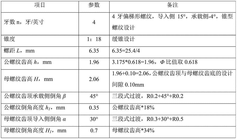
Further design, for 273.05 x 12.57mm box thread design, requires a thread load safety factor greater than 1.1.
The cross-sectional area of the specification sleeve is 11270mm2When the cutter is naturally withdrawn, the axial length of the non-full-top thread is 64mm, and the bearing area is about 4424mm calculated according to 1/3 of the full-top thread with the same length2. When the length of the full-top thread is 40mm through calculation, the full-top thread bears 8080mm2And checking the safety factor of thread bearing.

And the design requirements are met.
Example 3
In this example, the following design was made using the method of example 1:
it should be noted that, taking the ratio Φ between the tooth height and the tooth width of the thread to be 0.618, the tooth profile design of the buttress thread with different pitches is shown in table 2:
TABLE 2
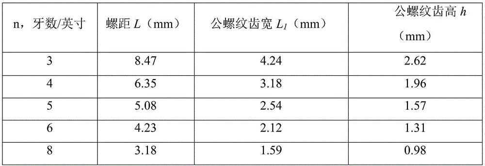
The API buttress thread has the thread number of 5 threads/inch, the thread pitch of 5.08mm and the thread height of 1.5748mm, and the thread height of 5 threads/inch calculated by the design method is 1.57mm, which are very close to each other, thereby proving the scientificity of the design method. Unlike other buttress threads, which are API standard 5 threads/inch, their corresponding thread height can be calculated according to the present design method.
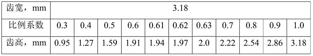
The design method is analyzed by finite element calculations. Taking a four-tooth profile (with a tooth width of 3.18mm) as an example, comparing the strain under different tooth heights, the tooth side is uniformly loaded, the bearing side is at-4 degrees, the leading side is at +10 degrees, and the model is established as shown in fig. 1:
the tooth height proportionality coefficient was 0.3 to 1.0, and for the purpose of studying the tooth height at different ratios of thread tooth height to tooth width, 0.6 to 0.7 were subdivided into 0.61, 0.62, and 0.63, and the tooth height values for each ratio are shown in table 3 below.
TABLE 3
The tooth height-strain numerical analysis graph is shown in fig. 2, and the fitting equation of the strain is as follows:
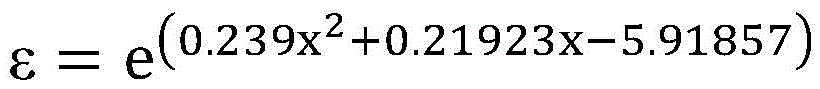
wherein:
x-tooth height variation, mm;
epsilon-strain;
e-natural logarithm;
under the same tooth width of 3.18mm, the strain increases with the increase of the tooth height, when the tooth height is less than 2.0mm, the strain is less than 0.01 and increases slowly, and when the tooth height exceeds 2.0mm, the strain acceleration is improved, the 2mm tooth height is considered to be a critical state of strain, and the tooth height range of the tooth height to the tooth width ratio within the range of 0.61-0.63 is 1.94-2.0 mm. Therefore, under the condition of determining the tooth width, the tooth height can be scientifically designed by applying the method, and finite element calculation analysis shows that the tooth structure with the ratio of the tooth height to the tooth width within the range of 0.61-0.63 has more mechanical stability, high bearing capacity and small deformation. Therefore, the tooth profile structure with the ratio of the tooth height to the tooth width in the range of 0.61 to 0.63 is more advantageous.
In the aspect of reducing the collision sensitivity of the threads during the buckling/tripping of the threads, the technical scheme adopted by the invention is that the mode of chamfering first and then rounding is adopted, namely, chamfering is carried out by using a large angle, and then rounding with small radian is carried out at the two ends of the chamfer, and the design reduces the tip rounding of the buckling/tripping tooth crest and can increase the contact radian. When the threads are buckled/disengaged, the direct contact between the tooth top and the tooth side fillet is changed into the contact between the fillet and the conical surface, and the contact stress is effectively reduced. The method comprises the following steps:
when the female thread is fastened, the leading-in side of the tooth crest of the female thread is chamfered, the chamfer angle alpha is formed, and the chamfer height H of the tooth crest of the female thread is formed1The tooth height of the female thread is 20-40%; when tripping off, chamfering the bearing side of the tooth crest of the male thread, wherein the chamfering angle is beta, and the height h is1The tooth height of the male thread is 10-30%; and: alpha is 20-40 degrees, beta is 40-60 degrees.
The method comprises the following steps:
during make-up, a three-section gradual transition design which mainly adopts chamfers is carried out on the leading-in side of the tooth crest of the female thread, as shown in figures 3 and 4, when make-up is carried out, under the condition that two ends are single fillets, the tooth crest fillet 15 of the male thread is directly contacted with the tooth crest fillet 25 of the female thread, and because the radian of the fillets is very small, the contact stress of the two is high, and the threads are easy to collide and damage during gravity make-up; the invention changes the leading-in side round angle 25 of the female thread, and designs the leading-in side round angle 25 into the round angle 27 and 28 by chamfering 26 and then designing the round angles at two ends of the chamfer, so that the design has the advantages that the leading-in side round angle 25 of the tooth top of the female thread is changed into the three-section type gradual transition design of the round angle 26, the chamfer 27 and the round angle 28, compared with the single round angle 25, the transition mode is more moderate, and the risk of thread damage caused by collision can be effectively reduced. During make-up, pin thread addendum fillet 15 and box thread addendum chamfer 26 contact, again along chamfer 26 upwards slide, through fillet 27 until entering box thread tooth bottom.
During tripping, chamfer design is carried out on the bearing side of the tooth crest of the male thread, as shown in fig. 5 and 6, during tripping, under the condition that two ends are single fillets, the tooth crest fillet 29 of the female thread is in direct contact with the tooth crest fillet 19 of the male thread, because the radian of the fillet is very small, the stress of the contact between the two is high, and the threads are easily damaged by collision when the tension is tripped. The bearing side round angle 19 of the male thread is changed, and the bearing side round angle is designed to be round angles 17 and 18 after the round angles 16 and 18 are designed at two ends of the round angle, so that the design has the advantages that the bearing side round angle 19 of the tooth top of the male thread is changed into a three-section type gradual transition design of the round angle 17, the round angle 16 and the round angle 18, compared with a single round angle 19, the transition mode is more moderate, and the risk of thread damage caused by collision can be effectively reduced. When tripping, the tooth crest fillet 29 of the female thread is contacted with the tooth crest chamfer 16 of the male thread, and then slides upwards along the chamfer 16, and passes through the fillet 18 until the male thread and the female thread are completely separated.
As shown in figure 7, on the premise of determining the number of teeth, the taper and the tooth form, the design of the petroleum sleeve thread buttress tooth form thread is carried out according to the ratio of the tooth height to the tooth width within the range of 0.61-0.63, and a three-section gradual transition design for reducing the collision sensitivity is adopted in the detailed design of the thread tooth crest fillet. The tooth profile of this design has the proportional relation of uniform harmony between each profile size, still has stable mechanical structure, excellent bearing performance. Adopt the gradual transition design of syllogic in the sensitive district that collides with, this kind of transition mode is more mitigateed, can reduce the risk of colliding with damage screw thread when make-up/tripping.
Claims (5)
1. A method for designing buttress thread of an oil casing is characterized by comprising the following steps: the thread width of the thread on the initial design side is half of the thread pitch, and the ratio Φ of the thread height to the thread width of the initial design side is: 0.61-0.63.
2. The method for designing buttress thread of oil casing according to claim 1, which is characterized in that:
the design method comprises the following steps of obtaining a male thread tooth form structure on one side of the sleeve through the following formula, wherein a female thread tooth form structure on the other side is determined by a design clearance of male and female threads in a matched mode:
L=25.4/n
L1=0.5L
h=L1*Φ
L2=L1-△L
H=h+△h
the design method comprises the following steps of obtaining a female thread tooth form structure on one side of the sleeve through the following formula, and determining a male thread tooth form structure on the other side of the sleeve according to a design clearance of male and female threads in matching:
L=25.4/n
L2=0.5L
H=L2*Φ
L1=L2+△L
h=H-△h
wherein: n-number of teeth; l-pitch; l is1-a pin thread width; l is2-a female thread tooth width; h-female thread tooth height; h-height of the male thread; phi-the ratio of tooth height to tooth width of the thread; the design clearance of the tooth sides of the male and female threads is delta L; and delta h is the designed clearance between the top and the bottom of the male and female thread teeth.
3. The method for designing buttress thread of oil casing according to claim 1 or 2, characterized in that:
in order to reduce the screw thread addendum bump risk in sleeve pipe make-up and the release, the regional three-section type that uses the chamfer as the main of colliding with gradually slows down the transition design, and is concrete:
when the thread is fastened, the leading-in side of the tooth crest of the female thread is chamfered, the chamfer angle is alpha, and the height H1The tooth height of the female thread is 20-40%; when tripping off, chamfering the bearing side of the tooth crest of the male thread, wherein the chamfering angle is beta, and the height h is1The tooth height of the male thread is 10-30%; and: alpha ═20~40°,β=40~60°。
4. The method for designing buttress thread of oil casing according to claim 1, which is characterized in that:
the thread designed by the design method can be a tapered thread or a stepped thread, and the bearing side of the thread can be at a positive angle or a negative angle.
5. The method for designing buttress thread of oil casing according to claim 1, which is characterized in that:
the design method can design buttress thread with any number of threads.
Priority Applications (1)
| Application Number | Priority Date | Filing Date | Title |
|---|---|---|---|
| CN202110198371.5A CN113027353B (en) | 2021-02-22 | 2021-02-22 | Method for designing buttress thread type thread of petroleum casing pipe |
Applications Claiming Priority (1)
| Application Number | Priority Date | Filing Date | Title |
|---|---|---|---|
| CN202110198371.5A CN113027353B (en) | 2021-02-22 | 2021-02-22 | Method for designing buttress thread type thread of petroleum casing pipe |
Publications (2)
| Publication Number | Publication Date |
|---|---|
| CN113027353A true CN113027353A (en) | 2021-06-25 |
| CN113027353B CN113027353B (en) | 2022-11-08 |
Family
ID=76461008
Family Applications (1)
| Application Number | Title | Priority Date | Filing Date |
|---|---|---|---|
| CN202110198371.5A Active CN113027353B (en) | 2021-02-22 | 2021-02-22 | Method for designing buttress thread type thread of petroleum casing pipe |
Country Status (1)
| Country | Link |
|---|---|
| CN (1) | CN113027353B (en) |
Citations (8)
| Publication number | Priority date | Publication date | Assignee | Title |
|---|---|---|---|---|
| CN200961451Y (en) * | 2006-07-11 | 2007-10-17 | 天津钢管集团有限公司 | Tooth breadth variable inverse trapezia bush screw connection structure |
| CN201574696U (en) * | 2009-12-10 | 2010-09-08 | 天津钢管集团股份有限公司 | Large-caliber fast screwing-up sleeve thread connecting structure |
| CN101881139A (en) * | 2010-07-07 | 2010-11-10 | 天津天钢石油专用管制造有限公司 | Thread connector of petroleum gas industrial tube |
| CN202348143U (en) * | 2011-12-15 | 2012-07-25 | 山东明珠石油装备制造有限公司 | Novel drill rod joint thread |
| AU2012101304A4 (en) * | 2011-09-02 | 2012-09-27 | Sharpe Engineering (Roma) Pty Ltd | A threaded bore casing |
| CN104453738A (en) * | 2013-12-18 | 2015-03-25 | 宝山钢铁股份有限公司 | Airtight seal sleeve joint |
| CN106761462A (en) * | 2016-12-27 | 2017-05-31 | 中国石油天然气集团公司 | A kind of oil well casing special nipple |
| CN107762425A (en) * | 2017-10-30 | 2018-03-06 | 中国石油天然气集团公司 | A kind of oil pipe thread attachment structure |
-
2021
- 2021-02-22 CN CN202110198371.5A patent/CN113027353B/en active Active
Patent Citations (8)
| Publication number | Priority date | Publication date | Assignee | Title |
|---|---|---|---|---|
| CN200961451Y (en) * | 2006-07-11 | 2007-10-17 | 天津钢管集团有限公司 | Tooth breadth variable inverse trapezia bush screw connection structure |
| CN201574696U (en) * | 2009-12-10 | 2010-09-08 | 天津钢管集团股份有限公司 | Large-caliber fast screwing-up sleeve thread connecting structure |
| CN101881139A (en) * | 2010-07-07 | 2010-11-10 | 天津天钢石油专用管制造有限公司 | Thread connector of petroleum gas industrial tube |
| AU2012101304A4 (en) * | 2011-09-02 | 2012-09-27 | Sharpe Engineering (Roma) Pty Ltd | A threaded bore casing |
| CN202348143U (en) * | 2011-12-15 | 2012-07-25 | 山东明珠石油装备制造有限公司 | Novel drill rod joint thread |
| CN104453738A (en) * | 2013-12-18 | 2015-03-25 | 宝山钢铁股份有限公司 | Airtight seal sleeve joint |
| CN106761462A (en) * | 2016-12-27 | 2017-05-31 | 中国石油天然气集团公司 | A kind of oil well casing special nipple |
| CN107762425A (en) * | 2017-10-30 | 2018-03-06 | 中国石油天然气集团公司 | A kind of oil pipe thread attachment structure |
Also Published As
| Publication number | Publication date |
|---|---|
| CN113027353B (en) | 2022-11-08 |
Similar Documents
| Publication | Publication Date | Title |
|---|---|---|
| JP4930647B1 (en) | Threaded joints for pipes | |
| WO2003076837A3 (en) | Wedgethread pipe connection | |
| JP6512586B2 (en) | Steel pipe screw joint | |
| US6572315B1 (en) | Threaded fastener having a thread crest greater than its thread root | |
| NL8203572A (en) | SCREW COUPLER CONNECTION. | |
| WO2016056222A1 (en) | Threaded joint for steel pipe | |
| JP7367069B2 (en) | threaded fittings for pipes | |
| CN114026309A (en) | Threaded joint for steel pipe | |
| EP3409991A1 (en) | Threaded joint for steel pipe | |
| WO2017145192A1 (en) | Threaded joint for steel pipes | |
| CN113027353B (en) | Method for designing buttress thread type thread of petroleum casing pipe | |
| CN114270012B (en) | Threaded joint | |
| GB2074280A (en) | Screw Thread Fasteners | |
| CN112601908A (en) | Threaded joint for steel pipe | |
| KR101417350B1 (en) | Universal tapping screw and fixing method using the same | |
| CN110410024B (en) | Variable tooth width screwed joint | |
| CN202417340U (en) | Threading connector for oil well pipe | |
| JP6703191B2 (en) | Threaded joint for steel pipe | |
| CN2504380Y (en) | Sleeving nipple | |
| CN108952595B (en) | Air-tight seal threaded joint | |
| CN110608321A (en) | Double-line marine riser joint | |
| JP6501578B2 (en) | Anti-seizure bolt | |
| CN219714194U (en) | Caliper for measuring multiple parameters of petroleum pipe coupling screw thread | |
| JP3668094B2 (en) | Pipe fitting | |
| CN208951083U (en) | Steel-wire screw-socket suitable for MJ screw thread |
Legal Events
| Date | Code | Title | Description |
|---|---|---|---|
| PB01 | Publication | ||
| PB01 | Publication | ||
| SE01 | Entry into force of request for substantive examination | ||
| SE01 | Entry into force of request for substantive examination | ||
| GR01 | Patent grant | ||
| GR01 | Patent grant |