CN113015463B - Configuration system for guiding at least one movable furniture part - Google Patents
Configuration system for guiding at least one movable furniture part Download PDFInfo
- Publication number
- CN113015463B CN113015463B CN201980074424.3A CN201980074424A CN113015463B CN 113015463 B CN113015463 B CN 113015463B CN 201980074424 A CN201980074424 A CN 201980074424A CN 113015463 B CN113015463 B CN 113015463B
- Authority
- CN
- China
- Prior art keywords
- furniture
- furniture part
- running track
- load
- parking position
- Prior art date
- Legal status (The legal status is an assumption and is not a legal conclusion. Google has not performed a legal analysis and makes no representation as to the accuracy of the status listed.)
- Active
Links
Images


Classifications
-
- E—FIXED CONSTRUCTIONS
- E05—LOCKS; KEYS; WINDOW OR DOOR FITTINGS; SAFES
- E05D—HINGES OR SUSPENSION DEVICES FOR DOORS, WINDOWS OR WINGS
- E05D15/00—Suspension arrangements for wings
- E05D15/06—Suspension arrangements for wings for wings sliding horizontally more or less in their own plane
- E05D15/0621—Details, e.g. suspension or supporting guides
- E05D15/0626—Details, e.g. suspension or supporting guides for wings suspended at the top
- E05D15/0652—Tracks
-
- A—HUMAN NECESSITIES
- A47—FURNITURE; DOMESTIC ARTICLES OR APPLIANCES; COFFEE MILLS; SPICE MILLS; SUCTION CLEANERS IN GENERAL
- A47B—TABLES; DESKS; OFFICE FURNITURE; CABINETS; DRAWERS; GENERAL DETAILS OF FURNITURE
- A47B88/00—Drawers for tables, cabinets or like furniture; Guides for drawers
- A47B88/40—Sliding drawers; Slides or guides therefor
- A47B88/483—Sliding drawers; Slides or guides therefor with single extensible guides or parts
- A47B88/487—Sliding drawers; Slides or guides therefor with single extensible guides or parts with rollers, ball bearings, wheels, or the like
-
- A—HUMAN NECESSITIES
- A47—FURNITURE; DOMESTIC ARTICLES OR APPLIANCES; COFFEE MILLS; SPICE MILLS; SUCTION CLEANERS IN GENERAL
- A47B—TABLES; DESKS; OFFICE FURNITURE; CABINETS; DRAWERS; GENERAL DETAILS OF FURNITURE
- A47B88/00—Drawers for tables, cabinets or like furniture; Guides for drawers
- A47B88/40—Sliding drawers; Slides or guides therefor
- A47B88/473—Braking devices, e.g. linear or rotational dampers or friction brakes; Buffers; End stops
- A47B88/477—Buffers; End stops
-
- A—HUMAN NECESSITIES
- A47—FURNITURE; DOMESTIC ARTICLES OR APPLIANCES; COFFEE MILLS; SPICE MILLS; SUCTION CLEANERS IN GENERAL
- A47B—TABLES; DESKS; OFFICE FURNITURE; CABINETS; DRAWERS; GENERAL DETAILS OF FURNITURE
- A47B88/00—Drawers for tables, cabinets or like furniture; Guides for drawers
- A47B88/40—Sliding drawers; Slides or guides therefor
- A47B88/483—Sliding drawers; Slides or guides therefor with single extensible guides or parts
-
- E—FIXED CONSTRUCTIONS
- E05—LOCKS; KEYS; WINDOW OR DOOR FITTINGS; SAFES
- E05D—HINGES OR SUSPENSION DEVICES FOR DOORS, WINDOWS OR WINGS
- E05D15/00—Suspension arrangements for wings
- E05D15/06—Suspension arrangements for wings for wings sliding horizontally more or less in their own plane
- E05D15/0621—Details, e.g. suspension or supporting guides
- E05D15/066—Details, e.g. suspension or supporting guides for wings supported at the bottom
- E05D15/0686—Tracks
-
- E—FIXED CONSTRUCTIONS
- E05—LOCKS; KEYS; WINDOW OR DOOR FITTINGS; SAFES
- E05D—HINGES OR SUSPENSION DEVICES FOR DOORS, WINDOWS OR WINGS
- E05D15/00—Suspension arrangements for wings
- E05D15/56—Suspension arrangements for wings with successive different movements
- E05D15/565—Suspension arrangements for wings with successive different movements for raising wings before sliding
-
- E—FIXED CONSTRUCTIONS
- E05—LOCKS; KEYS; WINDOW OR DOOR FITTINGS; SAFES
- E05D—HINGES OR SUSPENSION DEVICES FOR DOORS, WINDOWS OR WINGS
- E05D15/00—Suspension arrangements for wings
- E05D15/56—Suspension arrangements for wings with successive different movements
- E05D15/58—Suspension arrangements for wings with successive different movements with both swinging and sliding movements
-
- A—HUMAN NECESSITIES
- A47—FURNITURE; DOMESTIC ARTICLES OR APPLIANCES; COFFEE MILLS; SPICE MILLS; SUCTION CLEANERS IN GENERAL
- A47B—TABLES; DESKS; OFFICE FURNITURE; CABINETS; DRAWERS; GENERAL DETAILS OF FURNITURE
- A47B2210/00—General construction of drawers, guides and guide devices
- A47B2210/0002—Guide construction for drawers
- A47B2210/0029—Guide bearing means
- A47B2210/0037—Rollers
-
- A—HUMAN NECESSITIES
- A47—FURNITURE; DOMESTIC ARTICLES OR APPLIANCES; COFFEE MILLS; SPICE MILLS; SUCTION CLEANERS IN GENERAL
- A47B—TABLES; DESKS; OFFICE FURNITURE; CABINETS; DRAWERS; GENERAL DETAILS OF FURNITURE
- A47B2210/00—General construction of drawers, guides and guide devices
- A47B2210/0002—Guide construction for drawers
- A47B2210/0029—Guide bearing means
- A47B2210/0043—Wheels
-
- E—FIXED CONSTRUCTIONS
- E05—LOCKS; KEYS; WINDOW OR DOOR FITTINGS; SAFES
- E05Y—INDEXING SCHEME ASSOCIATED WITH SUBCLASSES E05D AND E05F, RELATING TO CONSTRUCTION ELEMENTS, ELECTRIC CONTROL, POWER SUPPLY, POWER SIGNAL OR TRANSMISSION, USER INTERFACES, MOUNTING OR COUPLING, DETAILS, ACCESSORIES, AUXILIARY OPERATIONS NOT OTHERWISE PROVIDED FOR, APPLICATION THEREOF
- E05Y2201/00—Constructional elements; Accessories therefor
- E05Y2201/60—Suspension or transmission members; Accessories therefor
- E05Y2201/622—Suspension or transmission members elements
- E05Y2201/684—Rails; Tracks
-
- E—FIXED CONSTRUCTIONS
- E05—LOCKS; KEYS; WINDOW OR DOOR FITTINGS; SAFES
- E05Y—INDEXING SCHEME ASSOCIATED WITH SUBCLASSES E05D AND E05F, RELATING TO CONSTRUCTION ELEMENTS, ELECTRIC CONTROL, POWER SUPPLY, POWER SIGNAL OR TRANSMISSION, USER INTERFACES, MOUNTING OR COUPLING, DETAILS, ACCESSORIES, AUXILIARY OPERATIONS NOT OTHERWISE PROVIDED FOR, APPLICATION THEREOF
- E05Y2201/00—Constructional elements; Accessories therefor
- E05Y2201/60—Suspension or transmission members; Accessories therefor
- E05Y2201/622—Suspension or transmission members elements
- E05Y2201/688—Rollers
-
- E—FIXED CONSTRUCTIONS
- E05—LOCKS; KEYS; WINDOW OR DOOR FITTINGS; SAFES
- E05Y—INDEXING SCHEME ASSOCIATED WITH SUBCLASSES E05D AND E05F, RELATING TO CONSTRUCTION ELEMENTS, ELECTRIC CONTROL, POWER SUPPLY, POWER SIGNAL OR TRANSMISSION, USER INTERFACES, MOUNTING OR COUPLING, DETAILS, ACCESSORIES, AUXILIARY OPERATIONS NOT OTHERWISE PROVIDED FOR, APPLICATION THEREOF
- E05Y2800/00—Details, accessories and auxiliary operations not otherwise provided for
- E05Y2800/40—Physical or chemical protection
- E05Y2800/406—Physical or chemical protection against deformation
- E05Y2800/407—Physical or chemical protection against deformation plastic deformation
-
- E—FIXED CONSTRUCTIONS
- E05—LOCKS; KEYS; WINDOW OR DOOR FITTINGS; SAFES
- E05Y—INDEXING SCHEME ASSOCIATED WITH SUBCLASSES E05D AND E05F, RELATING TO CONSTRUCTION ELEMENTS, ELECTRIC CONTROL, POWER SUPPLY, POWER SIGNAL OR TRANSMISSION, USER INTERFACES, MOUNTING OR COUPLING, DETAILS, ACCESSORIES, AUXILIARY OPERATIONS NOT OTHERWISE PROVIDED FOR, APPLICATION THEREOF
- E05Y2800/00—Details, accessories and auxiliary operations not otherwise provided for
- E05Y2800/40—Physical or chemical protection
- E05Y2800/422—Physical or chemical protection against vibration or noise
-
- E—FIXED CONSTRUCTIONS
- E05—LOCKS; KEYS; WINDOW OR DOOR FITTINGS; SAFES
- E05Y—INDEXING SCHEME ASSOCIATED WITH SUBCLASSES E05D AND E05F, RELATING TO CONSTRUCTION ELEMENTS, ELECTRIC CONTROL, POWER SUPPLY, POWER SIGNAL OR TRANSMISSION, USER INTERFACES, MOUNTING OR COUPLING, DETAILS, ACCESSORIES, AUXILIARY OPERATIONS NOT OTHERWISE PROVIDED FOR, APPLICATION THEREOF
- E05Y2800/00—Details, accessories and auxiliary operations not otherwise provided for
- E05Y2800/40—Physical or chemical protection
- E05Y2800/43—Physical or chemical protection against wear
-
- E—FIXED CONSTRUCTIONS
- E05—LOCKS; KEYS; WINDOW OR DOOR FITTINGS; SAFES
- E05Y—INDEXING SCHEME ASSOCIATED WITH SUBCLASSES E05D AND E05F, RELATING TO CONSTRUCTION ELEMENTS, ELECTRIC CONTROL, POWER SUPPLY, POWER SIGNAL OR TRANSMISSION, USER INTERFACES, MOUNTING OR COUPLING, DETAILS, ACCESSORIES, AUXILIARY OPERATIONS NOT OTHERWISE PROVIDED FOR, APPLICATION THEREOF
- E05Y2900/00—Application of doors, windows, wings or fittings thereof
- E05Y2900/20—Application of doors, windows, wings or fittings thereof for furniture, e.g. cabinets
Landscapes
- Engineering & Computer Science (AREA)
- Mechanical Engineering (AREA)
- Drawers Of Furniture (AREA)
- Support Devices For Sliding Doors (AREA)
- Bearings For Parts Moving Linearly (AREA)
- Extensible Doors And Revolving Doors (AREA)
- Cabinets, Racks, Or The Like Of Rigid Construction (AREA)
Abstract
Description
技术领域technical field
本发明涉及一种用于相对于一固定式家具部件引导至少一个可运动的家具部件的配置系统,所述至少一个可运动的家具部件特别是至少一个家具门或至少一个抽屉。本发明还涉及一种家具,该家具具有至少一个可运动的家具部件、一固定式家具部件以及至少一个此种配置系统。The invention relates to an arrangement system for guiding at least one movable furniture part, in particular at least one furniture door or at least one drawer, relative to a stationary furniture part. The invention also relates to a piece of furniture having at least one movable furniture part, a fixed furniture part and at least one such arrangement system.
背景技术Background technique
从现有技术中已知配置系统。Configuration systems are known from the prior art.
图1图示围绕转轴133可旋转地安装的滚动体106和现有技术中所使用的运行轨道107的组合。在此,在滚动体106的停放位置108上,由于滚动体106的负载,在滚动体106与运行轨道107的接触区域中可能发生压扁。若现在通过围绕转轴133的旋转使滚动体106从停放位置108中移出,则扁平部134首先从运行轨道107移开,在进一步的旋转运动中再度朝向运行轨道107运动,且然后再次与运行轨道107接触。滚动体106的圆形区域和扁平区域134之间在运行轨道107上的交替产生了令使用者觉得烦人的嘎吱声。FIG. 1 illustrates a combination of a
存在解决该问题的方法,包括为滚动体106设置塑料套,以避免滚动体106变平。然而,这无法解决所述问题,而只是推迟问题,因为塑料套迟早会破裂。There are solutions to this problem, including providing plastic sleeves for the
发明内容Contents of the invention
本发明的目的是提供一种相对于现有技术经改进的用于相对于固定式家具部件引导至少一个可运动的家具部件的配置系统,该配置系统避免了上述缺点,并提供一种具有此种改进的配置系统的家具。The object of the present invention is to provide an improved arrangement system for guiding at least one movable furniture part relative to a fixed furniture part, which avoids the above-mentioned disadvantages and provides an improved arrangement with respect to the prior art. An improved configuration system for furniture.
此目的通过本发明的用于相对于一固定式家具部件引导至少一个可运动的家具部件的配置系统来达成,所述至少一个可运动的家具部件特别是至少一个家具门或至少一个抽屉,该配置系统包括至少一个导轨和至少一个引导装置,所述至少一个导轨特别是待安装在该固定式家具部件上,所述至少一个引导装置特别是可与所述至少一个可运动的家具部件耦联,所述至少一个引导装置包含至少一个优选基本上为圆柱形的传递负载的滚动体,其中所述至少一个导轨包含至少一个运行轨道,所述至少一个传递负载的滚动体可运动地支承在该运行轨道上,所述至少一个运行轨道包含用于所述至少一个传递负载的滚动体的至少一个停放位置,并且所述至少一个停放位置对应于所述至少一个可运动的家具部件相对于该固定式家具部件的末端位置;所述至少一个传递负载的滚动体和所述至少一个运行轨道在整个运行轨道上经由设置在所述至少一个导轨的支撑结构上的支撑件被形成为:所述至少一个运行轨道可至少在所述至少一个停放位置的区域中变形伴随形成凹入的凹部,且所述至少一个传递负载的滚动体基本上形状稳定,并且至少在所述至少一个停放位置的区域中,所述至少一个传递负载的滚动体具有比所述至少一个运行轨道大的硬度。This object is achieved by the arrangement system according to the invention for guiding at least one movable furniture part, in particular at least one furniture door or at least one drawer, relative to a stationary furniture part, which The configuration system comprises at least one guide rail, in particular to be mounted on the stationary furniture part, and at least one guide device, in particular couplable with the at least one movable furniture part , said at least one guide device comprises at least one preferably substantially cylindrical load-transmitting rolling body, wherein said at least one guide rail comprises at least one running track on which said at least one load-transmitting rolling body is movably supported On the running track, the at least one running track contains at least one parking position for the at least one load-transmitting rolling body, and the at least one parking position corresponds to the relative position of the at least one movable furniture part to the fixed The end position of the type furniture part; the at least one load-transmitting rolling body and the at least one running track are formed over the entire running track via supports arranged on the supporting structure of the at least one guide rail: the at least A running track is deformable with the formation of concave recesses at least in the region of the at least one parking position, and the at least one load-transmitting rolling body is substantially dimensionally stable and at least in the region of the at least one parking position , the at least one load-transmitting rolling element has a greater hardness than the at least one running track.
亦即,本发明并非如现有技术那样试图来避免滚动体变平。而是在停放位置的区域中有意地压平,但不是在滚动体上,而是在至少一个运行轨道上。亦即,可在至少一个停放位置的区域中在至少一个运行轨道内形成凹部。然而,这不会导致烦人的噪音产生,这是因为凹部被设置在至少一个可运动的家具部件的末端位置中。亦即,至少一个传递负载的滚动体仅移入或移出凹部,但通常不必穿过凹部。如下的配置是一种例外:至少一个引导装置包括多于一个的传递负载的滚动体。在此情况下,在停放位置的区域中可能在运行轨道内形成多个凹部。当可运动的家具部件从末端位置移出时,可运动的家具部件可接着越过凹部,但是仅在停放位置的区域中越过,而不像现有技术中那样在沿着运行轨道的整个行进区域上越过。That is, the present invention does not attempt to avoid flattening of the rolling elements as in the prior art. Instead, in the area of the parking position, it is intentionally flattened, not on the rolling elements, but on at least one running track. This means that a recess can be formed in the at least one running track in the region of the at least one parking position. However, this does not lead to annoying noise generation, since the recess is provided in the end position of at least one movable furniture part. That is, the at least one load-transmitting rolling body only moves into or out of the recess, but usually does not have to pass through the recess. An exception is the configuration in which at least one guide device comprises more than one load-transmitting rolling body. In this case, in the region of the parking position, a plurality of recesses may be formed in the running track. When the movable furniture part is moved out of the end position, the movable furniture part can then move over the recess, but only in the area of the parking position, and not over the entire travel area along the running track as in the prior art over.
根据本发明的优选实施方式,如下设置:至少在所述至少一个停放位置的该区域中,所述至少一个传递负载的滚动体具有比所述至少一个运行轨道大的硬度。由此可确保:至少一个运行轨道可以在该区域中变形伴随形成凹部,至少一个传递负载的滚动体基本上形状稳定。According to a preferred embodiment of the invention, it is provided that at least in this region of the at least one parking position, the at least one load-transmitting rolling body has a greater hardness than the at least one running track. This ensures that at least one running track can be deformed in this region with formation of a recess and that at least one load-transmitting rolling body is substantially dimensionally stable.
出于稳定性的考虑,可以有利地如下设置:所述至少一个导轨包含支撑结构和至少一个支撑件,以用于形成所述至少一个运行轨道的至少一部分,该支撑结构优选由钢制成,所述至少一个支撑件优选由塑料制成,所述至少一个支撑件特别优选由聚甲醛制成。For reasons of stability, it can advantageously be provided that the at least one guide rail comprises a support structure and at least one support for forming at least a part of the at least one running track, the support structure preferably being made of steel, The at least one support part is preferably made of plastic, the at least one support part is particularly preferably made of polyoxymethylene.
在此情况下提供:所述至少一个支撑件是可替换的,和/或具有1mm至8mm、优选3mm的厚度。In this case it is provided that the at least one support is replaceable and/or has a thickness of 1 mm to 8 mm, preferably 3 mm.
根据优选实施方式,可设置至少一个锁止元件,所述至少一个支撑件可通过所述至少一个锁止元件固定在所述至少一个导轨上,优选地其中,所述至少一个锁止元件基本上形成为U形,和/或包含至少一个弹簧元件和/或至少一个摩擦元件,所述至少一个摩擦元件用于增加所述至少一个导轨的贴靠轮廓上的摩擦,该贴靠轮廓特别是形成为凹槽,和/或所述至少一个锁止元件包含至少一个操纵元件,所述至少一个锁止元件和与所述至少一个锁止元件连接的所述至少一个支撑件可通过所述至少一个操纵元件而运动,和/或设置至少一个卡锁装置,通过所述至少一个卡锁装置可将所述至少一个锁止元件可拆卸地固定在所述至少一个支撑件上,其中所述至少一个卡锁装置包含至少一个卡锁容纳部和至少一个卡锁突出部。According to a preferred embodiment, at least one locking element can be provided, by means of which the at least one support can be fixed on the at least one guide rail, preferably wherein the at least one locking element is substantially U-shaped and/or contain at least one spring element and/or at least one friction element for increasing the friction on the abutment contour of the at least one guide rail, which in particular forms is a groove, and/or the at least one locking element includes at least one manipulation element, the at least one locking element and the at least one support connected to the at least one locking element can pass through the at least one Manipulating the element to move, and/or setting at least one locking device, the at least one locking element can be detachably fixed on the at least one support by the at least one locking device, wherein the at least one The latch device comprises at least one latch receptacle and at least one latch projection.
已知用于引导例如悬吊门的导轨上的支撑件。然而,所述支撑件系用于降低噪音或最小化导轨磨损。此种支撑件与根据本发明所使用的支撑件不同,本发明所使用的支撑件与专门设计的滚动体结合使用,且本发明所使用的支撑件特别地允许在至少一个运行轨道的停放位置的区域上形成永久的凹部。Supports on guide rails for guiding eg suspended doors are known. However, the support is used to reduce noise or minimize rail wear. Such a support differs from the support used according to the invention, which is used in combination with specially designed rolling bodies and which in particular allows parking positions in at least one running track A permanent recess is formed in the area.
亦可如下设置:所述至少一个运行轨道在所述至少一个传递负载的滚动体的所述至少一个停放位置上可基本上不可逆地变形伴随形成该凹部。It can also be provided that the at least one running track is substantially irreversibly deformable in the at least one parking position of the at least one load-transmitting rolling element with formation of the recess.
以下可能发生:所述至少一个传递负载的滚动体可利用力而从在所述至少一个停放位置的该区域内在所述至少一个运行轨道中形成的该凹部移出。然而,这未必被用户认为是缺点。反之可为以下事实:使用者感觉到至少一个滚动体何时移入或移出凹部,甚至认为是正面的,这是因为使用者以这种方式领会到,其已经到达了可运动的家具部件相对于固定式家具部件的与至少一个停放位置相关联的末端位置。It can happen that the at least one load-transmitting rolling element can be displaced by force out of the recess formed in the at least one running track in the region of the at least one parking position. However, this is not necessarily considered a disadvantage by users. The opposite can be the fact that the user feels when at least one rolling body moves into or out of the recess, and even considers it positive, because the user understands in this way that he has reached the position of the movable furniture part relative to the An end position of the stationary furniture part associated with at least one parking position.
优选地如下设置:所述至少一个传递负载的滚动体至少部分地由钢形成,优选完全地由钢形成。It is preferably provided that the at least one load-transmitting rolling element is at least partially formed from steel, preferably completely formed from steel.
还可如下设置:所述至少一个运行轨道包含至少两个不同的材料区段,其中第一材料区段设置在所述至少一个停放位置的该区域中,且第二材料区段设置在与所述至少一个停放位置的该区域相接的动态区域中。藉此方式,可运动的家具部件的运行特性可被针对性地调校。It can also be provided that the at least one running track contains at least two different material sections, wherein a first material section is arranged in the region of the at least one parking position and a second material section is arranged in the same area as the at least one parking position. In the dynamic area adjacent to the area of the at least one parking position. In this way, the operating characteristics of the movable furniture part can be adjusted in a targeted manner.
替代性地或补充性地可如下设置:所述至少一个运行轨道的横截面至少局部是凹形的,和/或所述至少一个传递负载的滚动体包含如下周面,该周面的横截面是至少局部凸起的。这种配置提供如下优点:同时提供了侧向上的支撑。Alternatively or additionally it can be provided that the cross-section of the at least one running track is at least partially concave and/or that the at least one load-transmitting rolling body comprises a peripheral surface whose cross-section is at least partially convex. This configuration offers the advantage of providing lateral support at the same time.
以下被证实为有利的:该配置系统包括至少一个载体,所述至少一个可运动的家具部件可以优选可枢转地安装在所述至少一个载体上,且所述至少一个载体可与所述至少一个引导装置耦联,和/或该配置系统包含:至少一个横向轨道和至少一个滑块,所述至少一个横向轨道设置为或能设置为横向于所述至少一个导轨,所述至少一个滑块可与所述至少一个可运动的家具部件耦联,所述至少一个滑块可以可移动地安装在所述至少一个横向轨道上。It has proven to be advantageous if the configuration system comprises at least one carrier on which the at least one movable furniture part can be mounted, preferably pivotably, and which can be connected to the at least one A guiding device is coupled, and/or the configuration system comprises: at least one transverse rail and at least one slider, the at least one transverse rail is arranged or can be arranged transversely to the at least one guide rail, the at least one slider Couplable with the at least one movable furniture part, the at least one slider can be movably mounted on the at least one transverse rail.
如上所述,亦请求保护一种家具,该家具具有至少一个可运动的家具部件、固定式家具部件以及至少一个根据本发明的配置系统,所述至少一个可运动的家具部件特别是至少一个家具门或抽屉,所述至少一个配置系统用于相对于该固定式家具部件引导所述至少一个可运动的家具部件。As already mentioned above, a piece of furniture is also claimed which has at least one movable furniture part, in particular at least one furniture part, and at least one arrangement system according to the invention, a fixed furniture part A door or a drawer, said at least one deployment system for guiding said at least one movable furniture part relative to the fixed furniture part.
根据优选实施方式,如下设置:所述至少一个可运动的家具部件形成为家具门、特别是折叠推拉门,并且该家具包含至少一个内部空间和至少一个特别是竖井形的侧部空间,其中所述至少一个配置系统构造为用于并且在该家具上设置成用于,在关闭位置和打开位置之间相对于该固定式家具部件引导所述至少一个家具门,该关闭位置朝外覆盖所述至少一个内部空间,且该打开位置至少部分地收入所述至少一个侧部空间中,在该打开位置上使用者可自由接近所述至少一个内部空间。According to a preferred embodiment, it is provided that the at least one movable furniture part is formed as a furniture door, in particular as a folding sliding door, and that the furniture comprises at least one interior space and at least one, in particular shaft-shaped, side space, wherein the The at least one configuration system is configured for and arranged on the furniture for guiding the at least one furniture door relative to the fixed furniture part between a closed position and an open position, the closed position covering the At least one interior space, and the open position is at least partially received in the at least one side space, in which the user has free access to the at least one interior space.
在此情况下,以下被证实是有利的:用于引导所述至少一个家具门的该配置系统至少局部地在所述至少一个侧部空间的深度方向上延伸,且所述至少一个传递负载的滚动体的所述至少一个停放位置对应于所述至少一个家具门的基本上完全设置在所述至少一个侧部空间中的末端位置,优选地其中所述至少一个运行轨道包含用于所述至少一个传递负载的滚动体的另一停放位置,该另一停放位置对应于所述至少一个家具门的如下位置,在该位置上所述至少一个家具门设置为基本上平行于该固定式家具部件的所述至少一个侧部空间并且基本上完全在该固定式家具部件的所述至少一个侧部空间外部。In this case, it has proven to be advantageous that the arrangement system for guiding the at least one furniture door extends at least partially in the depth direction of the at least one side space, and that the at least one load-transferring The at least one parking position of the rolling bodies corresponds to the end position of the at least one furniture door which is arranged substantially completely in the at least one side space, preferably wherein the at least one running track contains a Another parking position of a load-transmitting roller body, which corresponds to a position of the at least one furniture door in which the at least one furniture door is arranged substantially parallel to the stationary furniture part and substantially completely outside said at least one side space of the stationary furniture part.
且最后以下被证实是有利的:该固定式家具部件包含至少一个侧面,所述至少一个侧面至少局部限定所述至少一个侧部空间,且用于引导所述至少一个家具门的该配置系统的所述至少一个导轨至少部分地设置在所述至少一个侧面上。And finally it has been found to be advantageous that the stationary furniture part comprises at least one side which at least partially delimits the at least one side space and which serves to guide the configuration system of the at least one furniture door. The at least one rail is at least partially disposed on the at least one side.
附图说明Description of drawings
以下将参考附图描述并参照附图更详细地阐释本发明的其他细节和优点。其中:Further details and advantages of the invention will be described below and explained in more detail with reference to the accompanying drawings. in:
图1图示根据现有技术的滚动体和运行轨道的组合,Figure 1 illustrates a combination of rolling elements and running tracks according to the prior art,
图2a)、b)以示意性透视图(子图a))和示意性侧视图(子图b))示出根据本发明的配置系统的优选实施例,2 a), b) show a preferred embodiment of the configuration system according to the invention in a schematic perspective view (sub-figure a)) and a schematic side view (sub-figure b)),
图3a)、b)各自以示意性侧视图图示滚动体和运行轨道的组合的两个优选实施例,Figure 3 a), b) each show two preferred embodiments of the combination of rolling elements and running tracks in a schematic side view,
图4以示意性截面图图示滚动体和运行轨道的组合的另一优选实施例,FIG. 4 shows another preferred embodiment of the combination of rolling elements and running tracks in a schematic sectional view,
图5a)-d)各自以示意性透视图图示具有两个折叠推拉门的家具的优选实施例,其中子图a)中的折叠推拉门设置在关闭位置上,在子图b)中其中一个折叠推拉门设置在弯折位置上,子图c)中的折叠推拉门设置在家具侧部空间之外的打开位置上,且子图d)中的折叠推拉门设置在家具的侧部空间之内的打开位置上,5a)-d) each show a schematic perspective view of a preferred embodiment of furniture with two folding sliding doors, wherein the folding sliding doors in sub-figure a) are arranged in the closed position, and in sub-figure b) wherein A folding sliding door is set in the bent position, the folding sliding door in sub-figure c) is set in the open position outside the side space of the furniture, and the folding sliding door in sub-figure d) is set in the side space of the furniture within the open position,
图6以示意性侧视图图示具有家具门的家具的另一优选实施例,其中家具门设置在家具的侧部空间外侧(实线)和内侧(虚线)的打开位置上,且6 shows a schematic side view of another preferred embodiment of a piece of furniture with a furniture door arranged in an open position on the outside (solid line) and inside (dotted line) of the side space of the piece of furniture, and
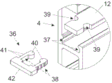
图7a)、b)以组装状态(子图a))与分解图(子图b))图示另一优选实施例的两个相关截面,在该实施例中设置支撑件,该支撑件通过锁止元件固定在导轨上。Figure 7 a), b) illustrate two relevant sections in assembled state (sub-figure a)) and in exploded view (sub-figure b)) of another preferred embodiment in which a support is provided, which is passed through The locking element is fixed on the guide rail.
具体实施方式Detailed ways
图1图示现有技术并且已经在本说明书的引言中被描述过。Figure 1 illustrates the prior art and has already been described in the introduction of this description.
图2a)、b)图示用于相对于固定式家具部件引导至少一个可运动的家具部件的配置系统1的优选实施例,所述至少一个可运动的家具部件特别是至少一个家具门或至少一个抽屉,该配置系统1包括导轨4和至少一个引导装置5,该导轨4特别是待安装在固定式家具部件上,所述至少一个引导装置5特别是可与至少一个可运动的家具部件耦联,所述至少一个引导装置5包含基本上呈圆柱形的传递负载的滚动体6,其中导轨4包含运行轨道7,传递负载的滚动体6可运动地支承在该运行轨道7上,运行轨道7包含用于传递负载的滚动体6的至少一个停放位置8、9(参见图3a)、b)),并且至少一个停放位置8、9对应于至少一个可运动的家具部件相对于固定式家具部件的末端位置。在此,传递负载的滚动体6和运行轨道7至少在至少一个停放位置8、9的区域中被形成为:运行轨道7可在此区域中变形伴随形成凹部10,且传递负载的滚动体6基本上形状稳定。2 a), b) illustrate a preferred embodiment of an
在具体图示的情况下,引导装置5包括两个传递负载的滚动体6。此外,设置用于侧向引导的引导滚轮32。In the specifically illustrated case, the
至少在至少一个停放位置8、9的区域中,传递负载的滚动体6具有比运行轨道7更大的硬度。反过来,这意味着至少在至少一个停放位置8、9的区域中,运行轨道7比传递负载的滚动体6更软。At least in the region of at least one
传递负载的滚动体6和运行轨道7的硬度可受多种因素影响。这包括对所用材料的选择和造型。The stiffness of the load-transmitting
在所图示的实施例中,导轨4包含由钢制成的支撑结构11和由塑料制成的支撑件12,伴随形成运行轨道7,该支撑件12优选地由聚甲醛制成。In the illustrated embodiment, the
支撑件12是可替换的,并且具有1mm至8mm,优选3mm的厚度13(也参见图3a)、b))。The
传递负载的滚动体6由钢制成。The load-transmitting
导轨4包含竖直窄片30和31,其中竖直窄片30和31连同支撑结构11一起限定了用于容纳支撑件12的凹槽。同时,引导滚轮32也贴靠在竖直窄片31上。The
传递负载的滚动体6围绕转轴33可旋转地安装,该转轴33在使用位置上基本上水平地定向。The load-transmitting
在所图示的情况下,配置系统1包括载体17,至少一个可运动的家具部件可以优选可枢转地安装在该载体17上,且该载体17与引导装置5耦联。In the illustrated case, the
图3a)、b)示出传递负载的滚动体6和运行轨道7的组合的两个优选实施例。3 a ), b) show two preferred embodiments of the combination of load-transmitting
在两种情况下,运行轨道7各自包含彼此间隔开的两个停放位置8和9,所述两个停放位置8和9各自对应于可运动的家具部件相对于固定式家具部件的末端位置,并且传递负载的滚动体6被安装成可在所述两个停放位置8和9之间运动,其中滚动体6在沿着运行轨道7运动时,绕该滚动体6的转轴33旋转。In both cases, the running
示意性地图示:传递负载的滚动体6和运行轨道7至少在停放位置8、9的区域中被形成为:运行轨道7可在这些区域中变形而形成凹部10,且传递负载的滚动体6基本上形状稳定。亦即,与图1中所图示的现有技术相比,在滚动体6上不会发生压扁。而是,在运行轨道7上宁可在停放位置8、9的区域中形成凹陷。Schematic illustration: the load-transmitting
在此,运行轨道7的变形可为基本上不可逆的。In this case, the deformation of the running
传递负载的滚动体6可利用力而从在停放位置8、9的区域内在运行轨道7中形成的凹部10移出。The load-transmitting
在图3b)中所图示的实施方式中,运行轨道7包含两个不同的材料区段14、15,其中第一材料区段14设置在停放位置8、9的区域中,且第二材料区段15设置在与停放位置8、9的区域相接的动态区域中。In the embodiment illustrated in FIG. 3 b ), the running
在图4中所图示的优选实施例中,运行轨道7的横截面至少局部是凹形的。同时,传递负载的滚动体6包含周面16,该周面16的横截面是局部凸起的。通过此种设计,可弃用如图2a)、b)中所图示的侧向引导滚轮32。In the preferred embodiment illustrated in FIG. 4 , the cross-section of the running
图5a)至d)图示家具20的优选实施例,其中优选可使用根据本发明的配置系统1。具体地,家具20包含:两个呈折叠推拉门形式的可运动的家具部件2、固定式家具部件3和配置系统1,该配置系统1用于相对于固定式家具部件3引导可运动的家具部件2。Figures 5a) to d) illustrate a preferred embodiment of a piece of
家具20包含内部空间21和两个竖井形的侧部空间22,其中配置系统1构成为用于并且在家具20上设置成用于,使得在关闭位置(参见图5a))和打开位置(参见图5d))之间相对于固定式家具部件3引导家具门2,该关闭位置朝外覆盖内部空间21,该打开位置至少部分地收入相应的侧部空间22中,在该打开位置上用户可自由接近内部空间21。在此之间,家具门2可处于中间位置,所述中间位置示出于图5b)和5c)中。The piece of
在图5c)和5d)中图示可运动家具门2与图3a)、b)中的两个停放位置8和9相对应的末端位置,其中至少一个传递负载的滚动体6的第一停放位置8各自对应于相应家具门2的基本上完全设置在侧部空间22中的末端位置(参见图5d)),其中用于至少一个传递负载的滚动体6的另一停放位置9对应于相应家具门2的如下位置,在该位置上家具门2设置为基本上平行于固定式家具部件2的相关联侧部空间22并且基本上完全在固定式家具部件的相关联侧部空间外部(参见图5c))。5c) and 5d) show the end positions of the
代替两个家具门2,亦可仅设置一个或多于两个家具门2。此外,家具门2可以仅由一个门扇构成,而非如图所示那样由通过门铰链26彼此铰接连接的两个门扇构成。Instead of two
用于引导家具门2的配置系统1各自局部地在两个侧部空间22的深度方向23上延伸。The
具体地可如下设置:固定式家具部件3包含多个侧面24,所述多个侧面24局部限定侧部空间22,其中用于引导家具门2的配置系统1的至少一个导轨4各自至少部分地设置在所设置的侧面24中的相应一个侧面上。In particular it can be provided that the
除了导轨4之外,配置系统1还包括基本上垂直于导轨4设置的横向轨道18,并且对于每个家具门2各包括一个与家具门2耦联的滑块19,该滑块19可以可运动地支承在横向轨道18上。滑块19可由载体17带动而在图5c)和d)中所示出的末端位置之间运动。横向轨道18可设置在固定式家具部件3的顶表面28上。In addition to the
每个家具门2还通过载体铰链29与载体17铰接连接。Each
家具20还亦可包括其他家具部件,例如柜25。The
如图所示,在固定式家具部件3的内部空间21中,优选地设置厨房家具27,例如具有抽屉的下方柜和/或上方柜。因此,可运动的家具部件2在不使用时用于覆盖由可运动的家具部件2形成的厨房。As shown, in the
图6图示家具20的另一个优选实施例。家具20包括具有侧面24的固定式家具部件3,该侧面24局部限定家具22的侧部空间。可运动的家具门2间接地通过载体17在如图所示的两个末端位置之间可运动地支承在侧面24上,且该载体17通过两个在竖直方向35上彼此间隔开的引导装置5可在两个导轨4上运动。两个导轨4中的至少一个导轨包含运行轨道7,引导装置5中的一个引导装置的至少一个传递负载的滚动体6可运动地支承在该运行轨道7上,其中传递负载的滚动体6和运行轨道7至少在对应于家具门3的末端位置的停放位置8、9的区域中被形成为:运行轨道7可在此区域中变形伴随形成凹部10,且传递负载的滚动体6基本上形状稳定。FIG. 6 illustrates another preferred embodiment of
在图7a)和7b)中图示另一个优选实施例,在该实施例中设置有支撑件12,该支撑件12通过锁止元件36固定在导轨4上。A further preferred embodiment is shown in FIGS. 7 a ) and 7 b ), in which case a
如图所示,锁止元件36可以是基本上U形的。As shown, the locking
该锁止元件36还可包含弹簧元件38。在所图示的情况下,该锁止元件36包含两个弹簧元件38,所述两个弹簧元件38基本上彼此平行定向并且形成该U形的两个竖直窄片。The locking
锁止元件36可包含至少一个摩擦元件41,所述至少一个摩擦元件41用于增加导轨4的贴靠轮廓上的摩擦,该贴靠轮廓特别形成为凹槽37。在此如下提供:设置数个例如横截面为三角形的摩擦元件41,所述摩擦元件41设置在弹簧元件38的外侧上。The locking
如下提供:锁止元件36如图所示包含操纵元件42,锁止元件36和与该锁止元件36连接的支撑件12可通过该操纵元件42而运动。操纵元件42可例如形成U形的底部并且在安装状态下从导轨4的端侧突出。以此方式,可特别容易地替换支撑件12。It is provided that the locking
最后,如下提供:设置至少一个卡锁装置,通过所述至少一个卡锁装置可将锁止元件36可拆卸地固定在支撑件12上,其中所述至少一个卡锁装置包含至少一个卡锁容纳部39和至少一个卡锁突出部40。在具体图示的情况下,卡锁突出部40各自设置在弹簧元件38的自由端处,该卡锁突出部40可卡扣到支撑件12上的对应的卡锁容纳部39中。Finally, it is provided that at least one latching device is provided, by means of which the
Claims (30)
Applications Claiming Priority (3)
| Application Number | Priority Date | Filing Date | Title |
|---|---|---|---|
| ATA50981/2018 | 2018-11-13 | ||
| ATA50981/2018A AT521372B1 (en) | 2018-11-13 | 2018-11-13 | Arrangement for guiding at least one movable furniture part |
| PCT/AT2019/060371 WO2020097648A1 (en) | 2018-11-13 | 2019-11-05 | Arrangement for guiding at least one movable furniture part |
Publications (2)
| Publication Number | Publication Date |
|---|---|
| CN113015463A CN113015463A (en) | 2021-06-22 |
| CN113015463B true CN113015463B (en) | 2023-03-10 |
Family
ID=68542541
Family Applications (1)
| Application Number | Title | Priority Date | Filing Date |
|---|---|---|---|
| CN201980074424.3A Active CN113015463B (en) | 2018-11-13 | 2019-11-05 | Configuration system for guiding at least one movable furniture part |
Country Status (9)
| Country | Link |
|---|---|
| US (1) | US11547211B2 (en) |
| EP (2) | EP3880032B1 (en) |
| JP (1) | JP7295233B2 (en) |
| CN (1) | CN113015463B (en) |
| AT (1) | AT521372B1 (en) |
| ES (1) | ES2964541T3 (en) |
| MY (1) | MY199777A (en) |
| TW (1) | TWI735077B (en) |
| WO (1) | WO2020097648A1 (en) |
Families Citing this family (1)
| Publication number | Priority date | Publication date | Assignee | Title |
|---|---|---|---|---|
| CN114270123B (en) * | 2019-08-27 | 2023-08-18 | 普和希株式会社 | Cooler |
Citations (6)
| Publication number | Priority date | Publication date | Assignee | Title |
|---|---|---|---|---|
| US4692035A (en) * | 1985-05-09 | 1987-09-08 | Julius Blum Gesellschaft M.B.H. | Extension pull-out guide assembly for drawers |
| DE4028878A1 (en) * | 1989-09-19 | 1991-03-28 | Fulterer Gmbh | Drawer slide with impact absorbing wedge inserts - has rubber wedge inserts in indented region of rail horizontal flange to absorb kinetic energy of drawer movement |
| US5580174A (en) * | 1993-08-27 | 1996-12-03 | Houck Industries, Inc. | Drawer slide assembly |
| CN107002438A (en) * | 2014-11-26 | 2017-08-01 | 尤利乌斯·布卢姆有限公司 | Ejecting device and the combined system including furniture and ejecting device |
| TW201829899A (en) * | 2017-01-13 | 2018-08-16 | 奧地利商朱利葉斯百隆股份有限公司 | An arrangement for guiding a sliding door or a folding-sliding door on a furniture wall |
| TW201831770A (en) * | 2017-01-13 | 2018-09-01 | 奧地利商朱利葉斯百隆股份有限公司 | Guide system for furniture parts |
Family Cites Families (19)
| Publication number | Priority date | Publication date | Assignee | Title |
|---|---|---|---|---|
| GB503472A (en) * | 1938-10-29 | 1939-04-06 | Educational Supply Ass Ltd | Improvements in and relating to roller fittings and runners for sliding and folding doors, partitions and windows |
| DE3332517A1 (en) * | 1983-09-09 | 1985-03-28 | Dietmar 6294 Weinbach Koch | Drawer or pull-out guide |
| DE3942584A1 (en) * | 1989-12-22 | 1991-06-27 | Weyel Kg | SLIDE-FOLDING DOOR SYSTEM FOR A CABINET |
| US5417496A (en) * | 1994-03-01 | 1995-05-23 | General Devices Co., Inc. | Ball bearing retainer for telescoping slide assembly |
| DE59600732D1 (en) * | 1995-08-21 | 1998-12-03 | Blum Gmbh Julius | Pull-out guide set for drawers |
| JP3715958B2 (en) * | 2002-10-18 | 2005-11-16 | 株式会社ムラコシ精工 | Folding door device |
| CH696416A5 (en) * | 2002-11-27 | 2007-06-15 | Lista Europ Holding Ag | Carcass rail for e.g. cabinets has C-shaped cross-section, upper surface of the lower arm supporting roller on drawer as it moves in and out and being made from harder material than rest of rail |
| AT504376B1 (en) * | 2006-10-18 | 2011-07-15 | Blum Gmbh Julius | EXTRACTION GUIDE FOR DRAWERS |
| DE102010016002A1 (en) * | 2010-03-17 | 2011-09-22 | Hettich-Heinze Gmbh & Co. Kg | roller guide |
| CN102197927A (en) * | 2010-03-23 | 2011-09-28 | 鸿富锦精密工业(深圳)有限公司 | Sliding rail |
| DE102011016165A1 (en) * | 2011-04-05 | 2015-04-02 | Raumplus Besitz- Und Entwicklungs-Gmbh & Co. Kg | Furniture with at least one sliding door |
| WO2013114730A1 (en) * | 2012-01-31 | 2013-08-08 | スガツネ工業株式会社 | Stowed folding door device |
| DE102012106751A1 (en) * | 2012-07-25 | 2014-01-30 | Paul Hettich Gmbh & Co. Kg | Pull-out guide for relatively movable furniture parts |
| AU2014258998A1 (en) * | 2013-04-22 | 2015-12-10 | Hardoor Top Design & Technology Ltd | System and device for soft closing |
| EP2992782B1 (en) * | 2014-09-03 | 2019-05-08 | Apparatebau Gronbach Srl | Slide assembly |
| AT516282B1 (en) * | 2014-11-26 | 2016-04-15 | Blum Gmbh Julius | Arrangement for spreading at least two hingedly connected door leaves |
| JP6392176B2 (en) * | 2015-06-25 | 2018-09-19 | 甲信工業株式会社 | Rail slider unit |
| DE102015121919A1 (en) * | 2015-12-16 | 2017-06-22 | Maco Technologie Gmbh | Lift-slide element |
| AT519752B1 (en) * | 2017-05-19 | 2018-10-15 | Fulterer Ag & Co Kg | pull-out |
-
2018
- 2018-11-13 AT ATA50981/2018A patent/AT521372B1/en active
-
2019
- 2019-11-05 JP JP2021525871A patent/JP7295233B2/en active Active
- 2019-11-05 ES ES19802035T patent/ES2964541T3/en active Active
- 2019-11-05 EP EP19802035.6A patent/EP3880032B1/en active Active
- 2019-11-05 CN CN201980074424.3A patent/CN113015463B/en active Active
- 2019-11-05 EP EP23189470.0A patent/EP4242405A3/en not_active Withdrawn
- 2019-11-05 MY MYPI2021002168A patent/MY199777A/en unknown
- 2019-11-05 WO PCT/AT2019/060371 patent/WO2020097648A1/en unknown
- 2019-11-11 TW TW108140817A patent/TWI735077B/en active
-
2021
- 2021-04-28 US US17/242,956 patent/US11547211B2/en active Active
Patent Citations (6)
| Publication number | Priority date | Publication date | Assignee | Title |
|---|---|---|---|---|
| US4692035A (en) * | 1985-05-09 | 1987-09-08 | Julius Blum Gesellschaft M.B.H. | Extension pull-out guide assembly for drawers |
| DE4028878A1 (en) * | 1989-09-19 | 1991-03-28 | Fulterer Gmbh | Drawer slide with impact absorbing wedge inserts - has rubber wedge inserts in indented region of rail horizontal flange to absorb kinetic energy of drawer movement |
| US5580174A (en) * | 1993-08-27 | 1996-12-03 | Houck Industries, Inc. | Drawer slide assembly |
| CN107002438A (en) * | 2014-11-26 | 2017-08-01 | 尤利乌斯·布卢姆有限公司 | Ejecting device and the combined system including furniture and ejecting device |
| TW201829899A (en) * | 2017-01-13 | 2018-08-16 | 奧地利商朱利葉斯百隆股份有限公司 | An arrangement for guiding a sliding door or a folding-sliding door on a furniture wall |
| TW201831770A (en) * | 2017-01-13 | 2018-09-01 | 奧地利商朱利葉斯百隆股份有限公司 | Guide system for furniture parts |
Also Published As
| Publication number | Publication date |
|---|---|
| CN113015463A (en) | 2021-06-22 |
| US20210244183A1 (en) | 2021-08-12 |
| EP3880032A1 (en) | 2021-09-22 |
| EP4242405A2 (en) | 2023-09-13 |
| AT521372B1 (en) | 2020-01-15 |
| WO2020097648A1 (en) | 2020-05-22 |
| EP4242405A3 (en) | 2023-12-13 |
| TWI735077B (en) | 2021-08-01 |
| US11547211B2 (en) | 2023-01-10 |
| AT521372A4 (en) | 2020-01-15 |
| EP3880032B1 (en) | 2023-08-16 |
| JP7295233B2 (en) | 2023-06-20 |
| ES2964541T3 (en) | 2024-04-08 |
| MY199777A (en) | 2023-11-22 |
| JP2022507351A (en) | 2022-01-18 |
| TW202031991A (en) | 2020-09-01 |
Similar Documents
| Publication | Publication Date | Title |
|---|---|---|
| TWI661794B (en) | Guide system and arrangement and funiture with the guide system | |
| US7108143B1 (en) | Sliding rail assembly for wire basket | |
| EP1169537B1 (en) | Crescent hinge | |
| US9228390B2 (en) | Safety door | |
| CN110191994B (en) | Guiding system for a door leaf | |
| TWI729555B (en) | An arrangement for guiding of a sliding door and a furniture with the arrangement | |
| CN113015463B (en) | Configuration system for guiding at least one movable furniture part | |
| US20140035298A1 (en) | Locking device, particularly for double-hung windows | |
| KR101252818B1 (en) | Locking device for sliding door | |
| KR102516646B1 (en) | shelf with cold cover for refrigerator | |
| RU2338451C2 (en) | Space divider | |
| KR101734034B1 (en) | Bottom Rail System for Folding Door | |
| KR200410168Y1 (en) | Sliding door opening and closing structure of bathroom cabinet | |
| EP3438389B1 (en) | Sliding apparatus for sliding door | |
| CN108350712B (en) | Guide assembly for sliding door and cabinet unit | |
| KR100748616B1 (en) | Door fixture | |
| CN108926117B (en) | Mechanical device for opening and closing a cover of a housing | |
| KR200385006Y1 (en) | Door for furniture | |
| KR200422091Y1 (en) | Door rail and door car of kitchen cupboard folding | |
| KR101746447B1 (en) | Structure of rotary door checker | |
| JP6726900B2 (en) | Guide member and fitting device including the same | |
| JP3534858B2 (en) | Folding door support structure | |
| JP3001891U (en) | Hinge for folding door | |
| US886531A (en) | Sliding-door fixture. | |
| KR200211625Y1 (en) | Mirror stand |
Legal Events
| Date | Code | Title | Description |
|---|---|---|---|
| PB01 | Publication | ||
| PB01 | Publication | ||
| SE01 | Entry into force of request for substantive examination | ||
| SE01 | Entry into force of request for substantive examination | ||
| GR01 | Patent grant | ||
| GR01 | Patent grant |