CN112996442A - Translation drive system for imaging system - Google Patents
Translation drive system for imaging system Download PDFInfo
- Publication number
- CN112996442A CN112996442A CN201980075965.8A CN201980075965A CN112996442A CN 112996442 A CN112996442 A CN 112996442A CN 201980075965 A CN201980075965 A CN 201980075965A CN 112996442 A CN112996442 A CN 112996442A
- Authority
- CN
- China
- Prior art keywords
- imaging
- base
- bracket
- rear surface
- gantry
- Prior art date
- Legal status (The legal status is an assumption and is not a legal conclusion. Google has not performed a legal analysis and makes no representation as to the accuracy of the status listed.)
- Granted
Links
Images


Classifications
-
- A—HUMAN NECESSITIES
- A61—MEDICAL OR VETERINARY SCIENCE; HYGIENE
- A61B—DIAGNOSIS; SURGERY; IDENTIFICATION
- A61B6/00—Apparatus or devices for radiation diagnosis; Apparatus or devices for radiation diagnosis combined with radiation therapy equipment
- A61B6/44—Constructional features of apparatus for radiation diagnosis
- A61B6/4476—Constructional features of apparatus for radiation diagnosis related to motor-assisted motion of the source unit
-
- A—HUMAN NECESSITIES
- A61—MEDICAL OR VETERINARY SCIENCE; HYGIENE
- A61B—DIAGNOSIS; SURGERY; IDENTIFICATION
- A61B6/00—Apparatus or devices for radiation diagnosis; Apparatus or devices for radiation diagnosis combined with radiation therapy equipment
- A61B6/02—Arrangements for diagnosis sequentially in different planes; Stereoscopic radiation diagnosis
- A61B6/03—Computed tomography [CT]
- A61B6/032—Transmission computed tomography [CT]
- A61B6/035—Mechanical aspects of CT
-
- A—HUMAN NECESSITIES
- A61—MEDICAL OR VETERINARY SCIENCE; HYGIENE
- A61B—DIAGNOSIS; SURGERY; IDENTIFICATION
- A61B6/00—Apparatus or devices for radiation diagnosis; Apparatus or devices for radiation diagnosis combined with radiation therapy equipment
- A61B6/44—Constructional features of apparatus for radiation diagnosis
Landscapes
- Health & Medical Sciences (AREA)
- Life Sciences & Earth Sciences (AREA)
- Engineering & Computer Science (AREA)
- Medical Informatics (AREA)
- Radiology & Medical Imaging (AREA)
- Molecular Biology (AREA)
- Biophysics (AREA)
- Nuclear Medicine, Radiotherapy & Molecular Imaging (AREA)
- Optics & Photonics (AREA)
- Pathology (AREA)
- Physics & Mathematics (AREA)
- Biomedical Technology (AREA)
- Heart & Thoracic Surgery (AREA)
- High Energy & Nuclear Physics (AREA)
- Surgery (AREA)
- Animal Behavior & Ethology (AREA)
- General Health & Medical Sciences (AREA)
- Public Health (AREA)
- Veterinary Medicine (AREA)
- Pulmonology (AREA)
- Theoretical Computer Science (AREA)
- Apparatus For Radiation Diagnosis (AREA)
Abstract
一种用于具有成像台架和台架基座的成像系统的平移驱动系统。该系统包括固定到成像台架的至少一个上轨和固定到基座的至少一个下轨,其中,下轨包括止动件。该系统还包括可移动地附接到下轨的前托架和下托架,其中,上轨可移动地附接到上托架以使得成像台架能够相对于基座移动。此外,该系统包括附接在下托架和成像台架之间的拉伸弹簧,其中,当下托架后表面接触止动件时,上轨水平地移动经过基座后表面进入延伸位置,其中,成像台架水平地延伸超过基座后表面。该系统还包括位于基座中的线性致动器,该线性致动器使成像台架移动。
A translation drive system for an imaging system having an imaging gantry and a gantry base. The system includes at least one upper rail secured to the imaging gantry and at least one lower rail secured to the base, wherein the lower rail includes a stop. The system also includes a front bracket and a lower bracket movably attached to the lower rail, wherein the upper rail is movably attached to the upper bracket to enable movement of the imaging gantry relative to the base. Additionally, the system includes an extension spring attached between the lower carriage and the imaging gantry, wherein when the lower carriage rear surface contacts the stopper, the upper rail moves horizontally past the base rear surface into an extended position, wherein, The imaging gantry extends horizontally beyond the rear surface of the base. The system also includes a linear actuator in the base that moves the imaging gantry.
Description
优先权要求priority claim
本申请在35 U.S.C. §119(e)下要求2018年11月19日提交的、名称为“用于成像系统的平移驱动系统”、律师案号为No. 2018P23477US的共同未决的美国临时申请No. 62/769,088以及2018年11月19日提交的、名称为“用于成像系统平移系统的线性延伸部”、律师案号为No. 2018P24450US的共同未决的美国临时申请No. 62/769,101的权益,这两篇美国临时申请通过引用整体结合于本文中,并且本申请要求其优先权的权益。This application claims, under 35 U.S.C. §119(e), co-pending U.S. Provisional Application No. 2018P23477US, entitled "Translational Drive System for Imaging Systems," filed on November 19, 2018 . 62/769,088 and co-pending U.S. Provisional Application No. 62/769,101, filed Nov. 19, 2018, entitled "Linear Extensions for Imaging System Translation Systems," Attorney Case No. 2018P24450US The benefit of these two US provisional applications is hereby incorporated by reference in their entirety, and this application claims the benefit of priority.
技术领域technical field
本发明的一个方面涉及一种用于具有成像台架(imaging gantry)和基座的成像系统的平移驱动系统,并且更具体地涉及一种平移驱动系统,其包括固定到成像台架的至少一个上轨和固定到基座的至少一个下轨以及可移动地附接到下轨的前托架和下托架,其中,上轨可移动地附接到上托架以使得成像台架能够相对于基座移动,其中,当下托架后表面接触止动件时,上轨水平地移动经过基座后表面进入延伸位置,其中,成像台架水平地延伸超过基座后表面。One aspect of the present invention relates to a translational drive system for an imaging system having an imaging gantry and a base, and more particularly to a translational drive system including at least one fixed to the imaging gantry an upper rail and at least one lower rail fixed to the base and a front bracket and a lower bracket movably attached to the lower rail, wherein the upper rail is movably attached to the upper bracket to enable the imaging gantry to be relative to each other In the base movement, wherein when the lower carriage rear surface contacts the stopper, the upper rail moves horizontally past the base rear surface into an extended position, wherein the imaging stage extends horizontally beyond the base rear surface.
背景技术Background technique
诸如那些利用计算机断层摄影(CT)或磁共振成像(MRI)技术的医疗成像系统需要精确(即,亚毫米)的平移驱动系统来执行患者的断层摄影图像的精确集合。这种平移驱动系统通常与患者台联接,其中,患者被精确地平移通过系统的成像孔。许多平移驱动系统包括许多部件,例如马达、齿轮、滑轮、反馈传感器等,这些部件提供通过一个或多个皮带和/或链条与实际负载联接的驱动运动。这产生了必须被精确地调整和/或校准以实现所需精度的复杂系统,因为皮带易受拉伸的影响并且驱动机构具有固有的回差(backlash)。此外,这种复杂的平移驱动机构占据了相当大的空间。Medical imaging systems such as those utilizing computed tomography (CT) or magnetic resonance imaging (MRI) techniques require precise (ie, sub-millimeter) translational drive systems to perform precise collection of tomographic images of a patient. Such translational drive systems are typically coupled with a patient table, where the patient is precisely translated through the imaging aperture of the system. Many translational drive systems include many components, such as motors, gears, pulleys, feedback sensors, etc., that provide drive motion coupled to the actual load through one or more belts and/or chains. This creates a complex system that must be precisely adjusted and/or calibrated to achieve the required accuracy, since the belt is susceptible to stretching and the drive mechanism has inherent backlash. Furthermore, such complex translational drive mechanisms take up considerable space.
另一方面,对于便携式CT成像系统,CT成像系统被平移,而患者保持静止。这对用于这种成像系统的平移驱动系统提出了几个挑战。特别是,用于便携式CT成像系统的平移驱动系统必须精确地平移显著更重的负载。此外,重心位于高于平移驱动系统的位置,这阻碍了提供期望精度的能力。此外,CT成像系统可以安装在紧急运输车辆中,例如救护车或救援车,被定向为相对较陡的倾斜度(即+/-约20度)。平移驱动系统显著地更难以实现期望的精度,因为平移驱动系统上的负载由于重力而移位。包括平移能力的便携式成像系统包括系统基座,该系统基座的尺寸与最大平移距离基本相同。希望减小系统基座的尺寸并提供一种机构,该机构能够使成像系统实现比系统基座的尺寸所提供的更大的平移距离。On the other hand, with a portable CT imaging system, the CT imaging system is translated while the patient remains stationary. This presents several challenges for translational drive systems for such imaging systems. In particular, translation drive systems for portable CT imaging systems must accurately translate significantly heavier loads. Additionally, the center of gravity is located higher than the translational drive system, which hinders the ability to provide the desired accuracy. Additionally, CT imaging systems can be installed in emergency transport vehicles, such as ambulances or rescue vehicles, oriented at relatively steep inclinations (ie +/- about 20 degrees). A translational drive system is significantly more difficult to achieve the desired accuracy because the load on the translational drive system is displaced due to gravity. Portable imaging systems that include translation capabilities include a system base that is substantially the same size as the maximum translation distance. It is desirable to reduce the size of the system base and provide a mechanism that enables the imaging system to achieve greater translation distances than the size of the system base provides.
发明内容SUMMARY OF THE INVENTION
一种用于具有成像台架和台架基座的成像系统的平移驱动系统。该系统包括固定到成像台架的至少一个上轨和固定到基座的至少一个下轨,其中,下轨包括止动件。该系统还包括可移动地附接到下轨的前托架和下托架,其中,上轨可移动地附接到上托架以使得成像台架能够相对于基座移动。此外,该系统包括附接在下托架和成像台架之间的拉伸弹簧,其中,当下托架后表面接触止动件时,上轨水平地移动经过基座后表面进入延伸位置,其中,成像台架水平地延伸超过基座后表面。该系统还包括线性致动器,该线性致动器使成像台架移动。A translation drive system for an imaging system having an imaging gantry and a gantry base. The system includes at least one upper rail secured to the imaging gantry and at least one lower rail secured to the base, wherein the lower rail includes a stop. The system also includes a front bracket and a lower bracket movably attached to the lower rail, wherein the upper rail is movably attached to the upper bracket to enable movement of the imaging gantry relative to the base. Additionally, the system includes an extension spring attached between the lower carriage and the imaging gantry, wherein when the lower carriage rear surface contacts the stopper, the upper rail moves horizontally past the base rear surface into an extended position, wherein, The imaging gantry extends horizontally beyond the rear surface of the base. The system also includes a linear actuator that moves the imaging gantry.
本领域技术人员可以以任何组合或子组合的方式联合地或分别地应用本发明的各个特征。Those skilled in the art may apply the various features of the invention jointly or separately in any combination or subcombination.
附图说明Description of drawings
在以下详细描述中结合附图进一步描述了本发明的示例性实施例,附图中:Exemplary embodiments of the invention are further described in the following detailed description in conjunction with the accompanying drawings, in which:
图1是根据本发明的一个方面的用于成像系统的直接平移驱动系统的俯视图。1 is a top view of a direct translation drive system for an imaging system according to one aspect of the present invention.
图2是沿图1的视图线2-2的驱动系统和成像系统的端视图。FIG. 2 is an end view of the drive system and imaging system along view line 2-2 of FIG. 1 .
图3是驱动系统和基座的透视图。Figure 3 is a perspective view of the drive system and base.
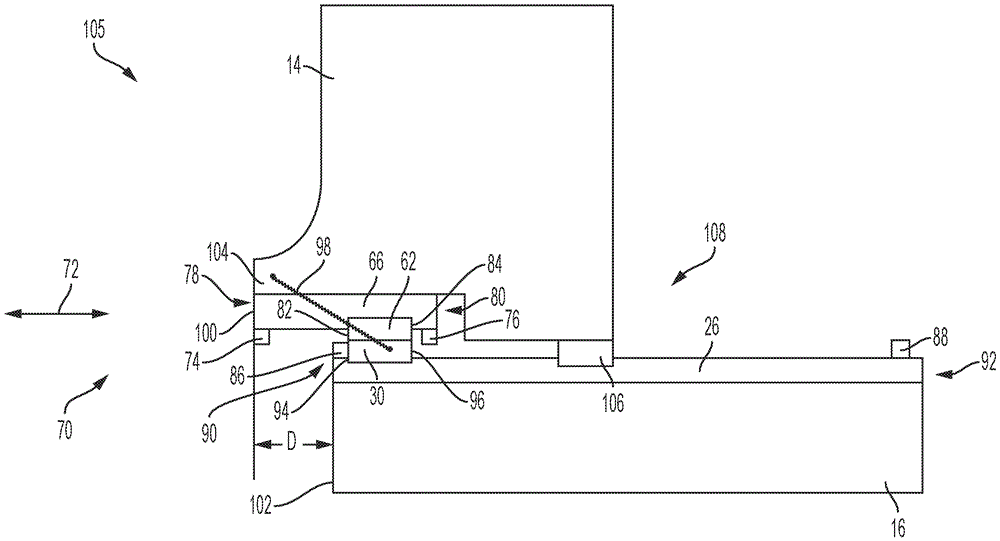
图4是线性延伸机构的局部侧视图,示出了处于延伸位置的上轨和水平地延伸超过台架基座的后表面的成像台架。4 is a partial side view of the linear extension mechanism showing the upper rail in an extended position and the imaging gantry extending horizontally beyond the rear surface of the gantry base.
图5是处于最后位置的延伸机构、成像台架和台架基座的总体侧视图。Figure 5 is a general side view of the extension mechanism, imaging gantry and gantry base in the rearmost position.
图6描绘了处于最前位置的成像台架。Figure 6 depicts the imaging gantry in the forward most position.
为了便于理解,在可能的情况下,使用相同的参考数字来表示附图中共有的相同元件。附图不是按比例绘制的。To facilitate understanding, where possible, the same reference numerals have been used to refer to the same elements that are common to the figures. The drawings are not to scale.
具体实施方式Detailed ways
尽管在本文中已经详细示出和描述了结合本公开的教导的各种实施例,但是本领域技术人员可以容易地设计出仍然结合这些教导的许多其他变化的实施例。本公开的范围在其应用中不限于在说明书中阐述的或在附图中示出的示例性实施例的构造细节和部件的布置。本公开涵盖了其它实施例并且以各种方式实施或执行。而且,应当理解,本文所使用的措辞和术语是为了描述的目的,而不应当被认为是限制。“包含”、“包括”或“具有”及其变型在本文中的使用旨在涵盖其后列出的项目及其等同物以及另外的项目。除非另外指定或限制,术语“安装”、“连接”、“支撑”和“联接”及其变型被广泛地使用,并且涵盖直接和间接的安装、连接、支撑和联接。此外,“连接”和“联接”不限于物理的或机械的连接或联接。Although various embodiments that incorporate the teachings of this disclosure have been shown and described in detail herein, those skilled in the art can readily devise many other varied embodiments that still incorporate these teachings. The scope of the disclosure is not limited in its application to the details of construction and the arrangement of components of the exemplary embodiments set forth in the specification or illustrated in the accompanying drawings. This disclosure covers other embodiments and can be implemented or carried out in various ways. Also, it is to be understood that the phraseology and terminology used herein is for the purpose of description and should not be regarded as limiting. The use of "comprising", "including" or "having" and variations thereof herein is intended to encompass the items listed thereafter and their equivalents as well as additional items. Unless otherwise specified or limited, the terms "mounted," "connected," "supported," and "coupled," and variations thereof, are used broadly and encompass both direct and indirect mounting, connecting, supporting, and coupling. Furthermore, "connected" and "coupled" are not limited to physical or mechanical connections or couplings.
参考图1,示出了用于成像系统12的直接平移驱动系统10的端视图。参考图2,示出了驱动系统10的俯视图,并沿图1的视图线2-2示出。结合图2参考图1,成像系统12可以是便携式成像系统,其具有可移动的成像台架14和位于成像台架14下方的单个静止的台架基座16。例如,成像台架14可以包括计算机断层摄影(CT)扫描设备,例如旋转X射线发生器18、X射线探测器20以及用于控制该设备并处理所获取的数据以便生成CT图像的各种相关联的电子硬件和软件。成像台架14还包括用于接收患者的患者孔22。成像台架14的重心24位于患者孔22中。替代地,成像台架14可以是磁共振成像(MRI)扫描器、正电子发射断层摄影(PET)扫描器、单光子发射计算机断层摄影(SPECT)扫描器、X射线扫描器,或者使用手术或介入技术。Referring to FIG. 1 , an end view of a direct
驱动系统10包括固定到基座16的至少一个长形滑轨。在实施例中,驱动系统10包括固定到基座16的间隔开的静止的第一下滑轨26和第二下滑轨28。第一下轨26和第二下轨28各自包括至少一个可移动的托架。在实施例中,第一下托架30和第二下托架32(以局部截面图示出)可移动地附接到第一下轨26以使得第一下托架30和第二下托架32能够相对于第一下轨26移动。此外,第三下托架34和第四下托架36可移动地附接到第二下轨28以使得第三下托架34和第四下托架36能够相对于第二下轨28移动。在本发明的一个方面中,下托架30、32、34、36各自附接到成像台架14的底部支撑元件38以使得成像台架14能够在基本平行于第一轨26和第二轨28的第一方向40上以及在与第一方向40相反的第二方向42上线性移动或平移。根据本发明的一个实施例,成像台架14的平移使得能够对患者进行扫描,以提供患者的断层摄影图像。第一下轨26和第二下轨28相对于重心24定位成使得第一下轨26和第二下轨28各自均等地支撑成像台架14的重量。这有助于使得驱动系统10能够实现成像台架14的精确平移。
驱动系统10还包括单个线性致动器44,其使成像台架14相对于第一下轨26和第二下轨28移动。在实施例中,线性致动器44包括单个滚珠丝杠46,其经由螺纹接合滚珠丝杠螺母48以形成滚珠丝杠机构55。滚珠丝杠螺母48附接到成像台架14的底部支撑元件38。驱动系统10还包括附接到滚珠丝杠46的端部52的马达50,诸如步进马达。另外,驱动系统10包括联接在马达50和计算机56之间的驱动器54,计算机56控制驱动器54。在使用中,马达50由驱动器54激励以引起滚珠丝杠46相对于滚珠丝杠螺母48顺时针或逆时针旋转。这进而使滚珠丝杠螺母48并因此使所附接的成像台架14在第一方向40或第二方向42上平移,以使得能够对患者进行扫描。在实施例中,使用大直径、小螺距的精密滚珠丝杠46,以便在被定向为相对陡峭的倾斜度(例如,大约+/-20度)时提供足够的机械利益,以便精确地移动成像台架14。在本发明的一个方面中,本发明使得能够使用相对小的马达50。The
马达50包括第一编码器58,其在成像台架14平移时检测滚珠丝杠46的旋转位置,并因此检测成像台架14的旋转位置。驱动系统10还可以包括第二编码器60,第二编码器60连接到成像台架14以直接测量成像台架14的位置。应当理解,可以使用其他线性致动器,例如线性马达、机电致动器等来移动成像台架14。根据本发明的一个方面,滚珠丝杠46、滚珠丝杠螺母48、马达50、第一编码器58和第二编码器60、第一下轨26和第二下轨28以及下托架30、32、34、36位于单个基座16中,该基座16位于成像台架14下方。因此,根据本发明的另一个方面,通过仅使用位于单个基座16中的单个线性致动器44(例如滚珠丝杠46和相关联的滚珠丝杠螺母48)来平移成像台架14。The
参考图3,示出了驱动系统10和基座16的透视图。根据本发明的一个方面,选定的托架(例如第一下托架30和第三下托架34)分别附接到第一上托架62和第二上托架64。第一上滑轨66和第二上滑轨68固定到底部支撑元件38,并从底部支撑元件38向下延伸。第一上轨66和第二上轨68分别可移动地附接到第一上托架62和第二上托架64。如将要描述的,第一上轨66和第二上轨68能够移动到延伸位置,其中,上轨66、68水平地延伸超过基座16以使得成像台架14能够相应地平移超过基座16。Referring to Figure 3, a perspective view of the
图4描绘了根据本发明的一个方面的用于驱动系统10的第一线性延伸机构70的局部侧视图。图4描绘了结合图3描述的第一上托架62和所附接的第一下托架30。如前面所描述的,第一上轨66和第一下轨26分别固定到成像台架14的底部支撑元件38和便携式成像系统12的基座16,其中,成像台架14被平移,并且基座16是静止的。第一下托架30可移动地附接到第一下轨26,以使托架62、30能够相对于第一下轨26在水平方向72上移动。第一上轨66可移动地附接到第一上托架62,以使第一上轨66能够相对于托架62、30和第一下轨26在水平方向72上移动。第一上托架62位于间隔开的第一上止动元件74和第二上止动元件76之间,第一上止动元件74和第二上止动元件76分别位于第一上轨66的后端78和前端80处。结合图4参考图5,第一下托架30位于间隔开的第三止动元件86和第四止动元件88之间,第三止动元件86和第四止动元件88分别位于第一下轨26的后端90和前端92处。在一个方面中,止动件86、88确保第一下托架30不会从第一下轨26滑落,并且止动件74、76确保第一上托架62不会从第一上轨66滑落。在一个实施例中,止动件74、76、86、88可以由诸如橡胶的弹性材料制成。FIG. 4 depicts a partial side view of the first
拉伸弹簧98被附接在第一下托架30和成像台架14之间。在图4中,第一上轨66被示出移动到延伸位置,其中,第一上轨66的轨后表面100水平地延伸超过基座16的基座后表面102达水平距离D,因此使弹簧98延伸。在延伸位置,第三止动件86也接触下托架后表面94。第一上轨66到延伸位置的移动引起成像台架14相对于基座后表面102的对应的水平移动,使得成像台架14的后表面104水平地延伸超过基座后表面102,因此将成像台架14定位在最后位置105。在一个实施例中,轨后表面100与成像台架后表面104对准,使得成像台架后表面104水平地延伸超过基座后表面102达距离D。A
参考图5,示出了第一延伸机构70、成像台架14和基座16的总体侧视图。第一延伸机构70还包括前托架106,其可移动地附接到第一下轨26并且位于第一下托架30和第四止动件88之间。成像台架14的前部108附接到前托架106。因此,成像台架14、第一上轨66、托架62、30和前托架106能够相对于第一下轨26和基座16在水平方向72上移动。参考图6,成像台架14被示出位于最前位置110,其中,前托架106位于第四止动件88附近,使得成像设备在最前位置110和最后位置105之间行进的距离足以使得扫描装置能够对患者进行扫描。另外,由弹簧98产生的弹簧张力引起上托架后表面82和第一止动件74之间的接触。5, a general side view of the
在本发明的一个实施例中,成像台架14附接到驱动元件,例如线性致动器44、马达驱动器或者引起成像台架14在最前位置110和最后位置105之间在水平方向72上的线性移动的其他装置。现在将参考图4-6描述根据本发明的一个实施例的示例性操作。在成像台架14从最前位置110向后移动112期间,由弹簧98产生的弹簧张力维持上托架后表面82和第一止动件74之间的接触,并且在下托架后表面94和第三止动件86之间的接触之前。因此,线性致动器44的激活引起成像台架14的向后移动112,这进而引起两个托架62、30在下托架后表面94和第三止动件86之间的接触之前相对于第一下轨26的对应的向后移动112。In one embodiment of the invention, the
托架62、30的移动随后在下托架后表面94和第三止动件86之间接触时停止。成像台架14和第一上轨66然后继续朝向最后位置105移动,其中,第一上轨66移动经过基座后表面102并且进入延伸位置。在延伸位置,轨后表面100和成像台架后表面104均水平地延伸超过基座后表面102,因此如前所述地使弹簧98延伸。在一个实施例中,成像台架后表面104延伸超过基座后表面102达水平距离D。因此,本发明的延伸机构70为成像台架14提供了大于基座16的尺寸的平移距离。此外,本发明的一个方面使得能够减小基座16的尺寸以提供具有增加的空间效率的便携式成像系统12。Movement of the
为了使成像台架14返回到最前位置110,线性致动器44使成像台架14在相反(向前)方向114上移动。随着成像台架14向前移动,在第一止动件74和上托架后表面82之间发生接触。然后,随着成像台架14向前移动,第一止动件74在向前方向114上推托架62、30,直到成像台架14处于最前位置110。To return the
根据本发明的一个方面,第二延伸机构70与第二下轨28结合使用,以使成像台架14在最后位置105和最前位置110之间移动。特别地,第二延伸机构70包括第一上轨66、第一上托架62和第一下托架30、前托架106、弹簧98和止动件74、76、86、88以及相关联的元件,其中,第一下托架30和前托架106均可移动地附接第二下轨28。此外,延伸机构70位于基座16中。According to one aspect of the present invention, the
在本发明的一个方面中,提供了一种精密驱动系统10,其具有减少数量的部件,从而使得能够减小基座16的尺寸。此外,本发明的驱动系统10可以容易地组装并且是结实耐用的。此外,驱动系统10避免了与常规平移驱动系统相关联的缺点,例如复杂性、回差以及需要对平移驱动系统进行校准。在本发明的另一方面中,提供了一种延伸机构70,其使得成像台架14的平移距离能够大于基座16的尺寸,从而也使得基座16的尺寸能够减小,以提供具有增加的空间效率的便携式成像系统12。In one aspect of the present invention, a
尽管已图示和描述了本公开的特定实施例,但对于本领域技术人员明显的是,在不背离本公开的精神和范围的情况下可作出各种其它变化和修改。因此,所附权利要求书旨在覆盖本公开的范围内的所有此类变化和修改。While particular embodiments of the present disclosure have been illustrated and described, it would be obvious to those skilled in the art that various other changes and modifications can be made without departing from the spirit and scope of the present disclosure. Accordingly, the appended claims are intended to cover all such changes and modifications as come within the scope of this disclosure.
Claims (20)
Applications Claiming Priority (5)
| Application Number | Priority Date | Filing Date | Title |
|---|---|---|---|
| US201862769101P | 2018-11-19 | 2018-11-19 | |
| US201862769088P | 2018-11-19 | 2018-11-19 | |
| US62/769101 | 2018-11-19 | ||
| US62/769088 | 2018-11-19 | ||
| PCT/US2019/057755 WO2020106403A1 (en) | 2018-11-19 | 2019-10-24 | Translation drive system for an imaging system |
Publications (2)
| Publication Number | Publication Date |
|---|---|
| CN112996442A true CN112996442A (en) | 2021-06-18 |
| CN112996442B CN112996442B (en) | 2024-06-25 |
Family
ID=68582371
Family Applications (1)
| Application Number | Title | Priority Date | Filing Date |
|---|---|---|---|
| CN201980075965.8A Active CN112996442B (en) | 2018-11-19 | 2019-10-24 | Translation drive system for imaging system |
Country Status (4)
| Country | Link |
|---|---|
| US (1) | US11813098B2 (en) |
| EP (1) | EP3866691B8 (en) |
| CN (1) | CN112996442B (en) |
| WO (1) | WO2020106403A1 (en) |
Citations (31)
| Publication number | Priority date | Publication date | Assignee | Title |
|---|---|---|---|---|
| US5097132A (en) * | 1990-11-21 | 1992-03-17 | Picker International, Inc. | Nuclear medicine camera system with improved gantry and patient table |
| JPH06263210A (en) * | 1993-03-11 | 1994-09-20 | Daifuku Co Ltd | Automated warehouse |
| CN1176585A (en) * | 1994-08-17 | 1998-03-18 | 斯特林普卢明集团公司 | A typical hidden screen with two or more overlapping sliding leaves |
| CN2280173Y (en) * | 1996-09-01 | 1998-04-29 | 中国船舶工业总公司第七研究院第七二二研究所 | Multi-section lead screw telescopic device |
| JP2000128310A (en) * | 1998-10-28 | 2000-05-09 | Toyota Autom Loom Works Ltd | Multistage fork device |
| KR20000019079U (en) * | 1999-04-01 | 2000-11-06 | 김인식 | Hydraulic clam crane |
| WO2004017832A2 (en) * | 2002-08-21 | 2004-03-04 | Breakaway Imaging, Llc | Gantry positioning apparatus for x-ray imaging |
| JP2004345891A (en) * | 2003-05-21 | 2004-12-09 | Maruni Toryo Kk | Drawer type craft furnace |
| CN1668246A (en) * | 2002-06-11 | 2005-09-14 | 分离成像有限责任公司 | Cantilever stand device for X-ray imaging |
| WO2008142695A1 (en) * | 2007-05-24 | 2008-11-27 | P-Cure Ltd. | Irradiation treatment apparatus and method |
| CN101637914A (en) * | 2009-08-24 | 2010-02-03 | 清华大学 | High-rigidity multi-stage expansion mechanism |
| US20100142669A1 (en) * | 2008-12-04 | 2010-06-10 | Jingyi Ren | Ct scanning device |
| CN102170829A (en) * | 2008-08-05 | 2011-08-31 | 通用电气公司 | Methods and apparatus for reducing the footprint of a multimodal imaging system |
| US20110222667A1 (en) * | 2010-03-12 | 2011-09-15 | Gregerson Eugene A | Drive system for imaging device |
| DE202012005039U1 (en) * | 2012-05-22 | 2012-07-11 | Franz Josef Decroupet | Mobile car wash |
| US20120256099A1 (en) * | 2011-04-07 | 2012-10-11 | Mobius Imaging, Llc | Mobile x-ray imaging system |
| US20120328077A1 (en) * | 2011-03-24 | 2012-12-27 | Bernard Bouvier | Multiplane medical imaging system |
| DE102012201529A1 (en) * | 2011-10-28 | 2013-05-02 | Siemens Aktiengesellschaft | Device comprising a linearly adjustable gantry of a computed tomography device |
| CN203028610U (en) * | 2013-01-21 | 2013-07-03 | 宁波健民电器有限公司 | Automatic reset sliding rail |
| US8505137B1 (en) * | 2008-01-22 | 2013-08-13 | Artec Imaging, Llc | Equine CT table |
| CN203209436U (en) * | 2013-03-28 | 2013-09-25 | 西门子Vai金属科技有限责任公司 | Rolling line adjusting device and rolling device |
| US20140037071A1 (en) * | 2012-08-06 | 2014-02-06 | Ulrich Foerner | Supply unit for a movable gantry |
| US20140275953A1 (en) * | 2013-03-15 | 2014-09-18 | Mobius Imaging, Llc | Mobile x-ray imaging system |
| US20140288696A1 (en) * | 2013-03-15 | 2014-09-25 | John Lert | Automated system for transporting payloads |
| US20150320376A1 (en) * | 2014-05-09 | 2015-11-12 | Kabushiki Kaisha Toshiba | X-ray ct apparatus |
| CN105167796A (en) * | 2015-09-30 | 2015-12-23 | 浙江大学 | Multifunctional cone-beam CT imaging system |
| EP2984989A1 (en) * | 2014-08-13 | 2016-02-17 | Samsung Electronics Co., Ltd. | Anatomical imaging system with scanning table movable along the x-axis and/or scanning table movable along the y-axis and the z-axis |
| CN105813570A (en) * | 2013-12-20 | 2016-07-27 | 通用电气公司 | Imaging system using independently controllable detectors |
| CN106347915A (en) * | 2016-11-08 | 2017-01-25 | 苏州博达特机电科技有限公司 | Multilevel stretching fork structure |
| CN106915584A (en) * | 2017-02-04 | 2017-07-04 | 苏州睿达矩自动化设备有限公司 | A kind of storage airborne carrier with three-level telescopic rail |
| US20180184994A1 (en) * | 2016-12-29 | 2018-07-05 | Samsung Electronics Co., Ltd. | Medical device |
Family Cites Families (11)
| Publication number | Priority date | Publication date | Assignee | Title |
|---|---|---|---|---|
| US4645933A (en) * | 1983-07-29 | 1987-02-24 | Picker International, Inc. | Emissive computed tomography |
| US4928283A (en) * | 1988-02-26 | 1990-05-22 | Analogic Corporation | X-ray tomography apparatus |
| US5107121A (en) * | 1989-10-27 | 1992-04-21 | Trionix Research Laboratory, Inc. | Gantry and pallet assembly used in nuclear imaging |
| JP4737808B2 (en) * | 2000-09-29 | 2011-08-03 | 株式会社東芝 | IVR-CT equipment |
| JP3860996B2 (en) * | 2001-11-19 | 2006-12-20 | ジーイー・メディカル・システムズ・グローバル・テクノロジー・カンパニー・エルエルシー | Gantry system, X-ray CT system and control method thereof |
| US6896234B2 (en) * | 2003-04-15 | 2005-05-24 | Cti Pet Systems, Inc. | Rail system for supporting and moving a patient gantry |
| EP2642924B1 (en) * | 2010-11-27 | 2020-02-26 | ICRCO, Inc | Computed tomography and tomosynthesis system |
| US10987068B2 (en) * | 2012-06-14 | 2021-04-27 | Mobius Imaging Llc | Multi-directional x-ray imaging system |
| KR101591784B1 (en) * | 2013-11-01 | 2016-02-04 | (주)메디엔인터내셔날 | Length adjustable detector arm and rail systmem comprising the same |
| ITUB20156291A1 (en) * | 2015-12-04 | 2017-06-04 | Imaginalis S R L | RADIOLOGICAL IMAGE DEVICE |
| JP2018134237A (en) * | 2017-02-22 | 2018-08-30 | キヤノンメディカルシステムズ株式会社 | Medical image diagnostic system |
-
2019
- 2019-10-24 WO PCT/US2019/057755 patent/WO2020106403A1/en not_active Ceased
- 2019-10-24 CN CN201980075965.8A patent/CN112996442B/en active Active
- 2019-10-24 US US17/292,804 patent/US11813098B2/en active Active
- 2019-10-24 EP EP19804949.6A patent/EP3866691B8/en active Active
Patent Citations (31)
| Publication number | Priority date | Publication date | Assignee | Title |
|---|---|---|---|---|
| US5097132A (en) * | 1990-11-21 | 1992-03-17 | Picker International, Inc. | Nuclear medicine camera system with improved gantry and patient table |
| JPH06263210A (en) * | 1993-03-11 | 1994-09-20 | Daifuku Co Ltd | Automated warehouse |
| CN1176585A (en) * | 1994-08-17 | 1998-03-18 | 斯特林普卢明集团公司 | A typical hidden screen with two or more overlapping sliding leaves |
| CN2280173Y (en) * | 1996-09-01 | 1998-04-29 | 中国船舶工业总公司第七研究院第七二二研究所 | Multi-section lead screw telescopic device |
| JP2000128310A (en) * | 1998-10-28 | 2000-05-09 | Toyota Autom Loom Works Ltd | Multistage fork device |
| KR20000019079U (en) * | 1999-04-01 | 2000-11-06 | 김인식 | Hydraulic clam crane |
| CN1668246A (en) * | 2002-06-11 | 2005-09-14 | 分离成像有限责任公司 | Cantilever stand device for X-ray imaging |
| WO2004017832A2 (en) * | 2002-08-21 | 2004-03-04 | Breakaway Imaging, Llc | Gantry positioning apparatus for x-ray imaging |
| JP2004345891A (en) * | 2003-05-21 | 2004-12-09 | Maruni Toryo Kk | Drawer type craft furnace |
| WO2008142695A1 (en) * | 2007-05-24 | 2008-11-27 | P-Cure Ltd. | Irradiation treatment apparatus and method |
| US8505137B1 (en) * | 2008-01-22 | 2013-08-13 | Artec Imaging, Llc | Equine CT table |
| CN102170829A (en) * | 2008-08-05 | 2011-08-31 | 通用电气公司 | Methods and apparatus for reducing the footprint of a multimodal imaging system |
| US20100142669A1 (en) * | 2008-12-04 | 2010-06-10 | Jingyi Ren | Ct scanning device |
| CN101637914A (en) * | 2009-08-24 | 2010-02-03 | 清华大学 | High-rigidity multi-stage expansion mechanism |
| US20110222667A1 (en) * | 2010-03-12 | 2011-09-15 | Gregerson Eugene A | Drive system for imaging device |
| US20120328077A1 (en) * | 2011-03-24 | 2012-12-27 | Bernard Bouvier | Multiplane medical imaging system |
| US20120256099A1 (en) * | 2011-04-07 | 2012-10-11 | Mobius Imaging, Llc | Mobile x-ray imaging system |
| DE102012201529A1 (en) * | 2011-10-28 | 2013-05-02 | Siemens Aktiengesellschaft | Device comprising a linearly adjustable gantry of a computed tomography device |
| DE202012005039U1 (en) * | 2012-05-22 | 2012-07-11 | Franz Josef Decroupet | Mobile car wash |
| US20140037071A1 (en) * | 2012-08-06 | 2014-02-06 | Ulrich Foerner | Supply unit for a movable gantry |
| CN203028610U (en) * | 2013-01-21 | 2013-07-03 | 宁波健民电器有限公司 | Automatic reset sliding rail |
| US20140275953A1 (en) * | 2013-03-15 | 2014-09-18 | Mobius Imaging, Llc | Mobile x-ray imaging system |
| US20140288696A1 (en) * | 2013-03-15 | 2014-09-25 | John Lert | Automated system for transporting payloads |
| CN203209436U (en) * | 2013-03-28 | 2013-09-25 | 西门子Vai金属科技有限责任公司 | Rolling line adjusting device and rolling device |
| CN105813570A (en) * | 2013-12-20 | 2016-07-27 | 通用电气公司 | Imaging system using independently controllable detectors |
| US20150320376A1 (en) * | 2014-05-09 | 2015-11-12 | Kabushiki Kaisha Toshiba | X-ray ct apparatus |
| EP2984989A1 (en) * | 2014-08-13 | 2016-02-17 | Samsung Electronics Co., Ltd. | Anatomical imaging system with scanning table movable along the x-axis and/or scanning table movable along the y-axis and the z-axis |
| CN105167796A (en) * | 2015-09-30 | 2015-12-23 | 浙江大学 | Multifunctional cone-beam CT imaging system |
| CN106347915A (en) * | 2016-11-08 | 2017-01-25 | 苏州博达特机电科技有限公司 | Multilevel stretching fork structure |
| US20180184994A1 (en) * | 2016-12-29 | 2018-07-05 | Samsung Electronics Co., Ltd. | Medical device |
| CN106915584A (en) * | 2017-02-04 | 2017-07-04 | 苏州睿达矩自动化设备有限公司 | A kind of storage airborne carrier with three-level telescopic rail |
Also Published As
| Publication number | Publication date |
|---|---|
| EP3866691B8 (en) | 2022-05-18 |
| EP3866691A1 (en) | 2021-08-25 |
| WO2020106403A1 (en) | 2020-05-28 |
| CN112996442B (en) | 2024-06-25 |
| US11813098B2 (en) | 2023-11-14 |
| EP3866691B1 (en) | 2022-03-16 |
| US20210393221A1 (en) | 2021-12-23 |
Similar Documents
| Publication | Publication Date | Title |
|---|---|---|
| US10874359B2 (en) | Caster system for mobile apparatus | |
| US9848841B2 (en) | X-ray stitching jig | |
| CN106974618B (en) | Method and apparatus for shortening the footprint of a multi-modality imaging system | |
| US10987070B2 (en) | Supporting device in medical diagnostics system | |
| US10314552B2 (en) | Bed apparatus and X-ray computed tomography apparatus | |
| US11457881B2 (en) | Anatomical imaging system with scanning table movable along the X-axis and/or scanning table movable along the Y-axis and the Z-axis | |
| US10966672B2 (en) | Sliding arrangement for mobile tomosynthesis X-ray system | |
| CN112996442A (en) | Translation drive system for imaging system | |
| EP2752159A1 (en) | X-ray imaging apparatus | |
| KR20090030890A (en) | Dental Composite Imaging Device | |
| CN101032406A (en) | Method and instrument for X-ray diagnosis of object to be examined | |
| US5010564A (en) | Dual axis translation mechanism | |
| JP2007136183A5 (en) | ||
| EP2858572B1 (en) | Imaging system subject support | |
| KR20090054447A (en) | Dental Composite Imaging Device | |
| CN107072630B (en) | Radiological apparatus having a platform movement system with a variable angle rod | |
| US20100301863A1 (en) | Mechanical pick-up with reduced impact force by using a potating intermediate part | |
| HK40067236A (en) | Ct imaging apparatus | |
| HK40067239A (en) | Ct imaging apparatus | |
| CN120131044A (en) | A synchronous linear motion linkage mechanism and X-ray imaging equipment | |
| CN115886857A (en) | A two-stage sample feeding system, device, method and scanning imaging system | |
| JP2023108694A (en) | diagnostic imaging system bed |
Legal Events
| Date | Code | Title | Description |
|---|---|---|---|
| PB01 | Publication | ||
| PB01 | Publication | ||
| SE01 | Entry into force of request for substantive examination | ||
| SE01 | Entry into force of request for substantive examination | ||
| TA01 | Transfer of patent application right |
Effective date of registration: 20230818 Address after: Pennsylvania, America Applicant after: Siemens Medical Solutions USA, Inc. Address before: New Hampshire Applicant before: Dedicated2Imaging, LLC |
|
| TA01 | Transfer of patent application right | ||
| GR01 | Patent grant | ||
| GR01 | Patent grant |