CN112880803B - Optical environment oscillation detection system and optical measurement method using same - Google Patents
Optical environment oscillation detection system and optical measurement method using same Download PDFInfo
- Publication number
- CN112880803B CN112880803B CN202110068462.7A CN202110068462A CN112880803B CN 112880803 B CN112880803 B CN 112880803B CN 202110068462 A CN202110068462 A CN 202110068462A CN 112880803 B CN112880803 B CN 112880803B
- Authority
- CN
- China
- Prior art keywords
- liquid crystal
- representing
- axis
- scattered light
- optical
- Prior art date
- Legal status (The legal status is an assumption and is not a legal conclusion. Google has not performed a legal analysis and makes no representation as to the accuracy of the status listed.)
- Active
Links
Images


Classifications
-
- G—PHYSICS
- G01—MEASURING; TESTING
- G01H—MEASUREMENT OF MECHANICAL VIBRATIONS OR ULTRASONIC, SONIC OR INFRASONIC WAVES
- G01H9/00—Measuring mechanical vibrations or ultrasonic, sonic or infrasonic waves by using radiation-sensitive means, e.g. optical means
-
- G—PHYSICS
- G02—OPTICS
- G02F—OPTICAL DEVICES OR ARRANGEMENTS FOR THE CONTROL OF LIGHT BY MODIFICATION OF THE OPTICAL PROPERTIES OF THE MEDIA OF THE ELEMENTS INVOLVED THEREIN; NON-LINEAR OPTICS; FREQUENCY-CHANGING OF LIGHT; OPTICAL LOGIC ELEMENTS; OPTICAL ANALOGUE/DIGITAL CONVERTERS
- G02F1/00—Devices or arrangements for the control of the intensity, colour, phase, polarisation or direction of light arriving from an independent light source, e.g. switching, gating or modulating; Non-linear optics
- G02F1/01—Devices or arrangements for the control of the intensity, colour, phase, polarisation or direction of light arriving from an independent light source, e.g. switching, gating or modulating; Non-linear optics for the control of the intensity, phase, polarisation or colour
- G02F1/13—Devices or arrangements for the control of the intensity, colour, phase, polarisation or direction of light arriving from an independent light source, e.g. switching, gating or modulating; Non-linear optics for the control of the intensity, phase, polarisation or colour based on liquid crystals, e.g. single liquid crystal display cells
- G02F1/1306—Details
- G02F1/1309—Repairing; Testing
-
- G—PHYSICS
- G01—MEASURING; TESTING
- G01N—INVESTIGATING OR ANALYSING MATERIALS BY DETERMINING THEIR CHEMICAL OR PHYSICAL PROPERTIES
- G01N21/00—Investigating or analysing materials by the use of optical means, i.e. using sub-millimetre waves, infrared, visible or ultraviolet light
- G01N21/17—Systems in which incident light is modified in accordance with the properties of the material investigated
- G01N21/21—Polarisation-affecting properties
-
- G—PHYSICS
- G01—MEASURING; TESTING
- G01N—INVESTIGATING OR ANALYSING MATERIALS BY DETERMINING THEIR CHEMICAL OR PHYSICAL PROPERTIES
- G01N21/00—Investigating or analysing materials by the use of optical means, i.e. using sub-millimetre waves, infrared, visible or ultraviolet light
- G01N21/17—Systems in which incident light is modified in accordance with the properties of the material investigated
- G01N21/47—Scattering, i.e. diffuse reflection
- G01N21/49—Scattering, i.e. diffuse reflection within a body or fluid
- G01N21/53—Scattering, i.e. diffuse reflection within a body or fluid within a flowing fluid, e.g. smoke
- G01N21/538—Scattering, i.e. diffuse reflection within a body or fluid within a flowing fluid, e.g. smoke for determining atmospheric attenuation and visibility
-
- G—PHYSICS
- G02—OPTICS
- G02F—OPTICAL DEVICES OR ARRANGEMENTS FOR THE CONTROL OF LIGHT BY MODIFICATION OF THE OPTICAL PROPERTIES OF THE MEDIA OF THE ELEMENTS INVOLVED THEREIN; NON-LINEAR OPTICS; FREQUENCY-CHANGING OF LIGHT; OPTICAL LOGIC ELEMENTS; OPTICAL ANALOGUE/DIGITAL CONVERTERS
- G02F1/00—Devices or arrangements for the control of the intensity, colour, phase, polarisation or direction of light arriving from an independent light source, e.g. switching, gating or modulating; Non-linear optics
- G02F1/01—Devices or arrangements for the control of the intensity, colour, phase, polarisation or direction of light arriving from an independent light source, e.g. switching, gating or modulating; Non-linear optics for the control of the intensity, phase, polarisation or colour
- G02F1/13—Devices or arrangements for the control of the intensity, colour, phase, polarisation or direction of light arriving from an independent light source, e.g. switching, gating or modulating; Non-linear optics for the control of the intensity, phase, polarisation or colour based on liquid crystals, e.g. single liquid crystal display cells
-
- G—PHYSICS
- G01—MEASURING; TESTING
- G01N—INVESTIGATING OR ANALYSING MATERIALS BY DETERMINING THEIR CHEMICAL OR PHYSICAL PROPERTIES
- G01N2201/00—Features of devices classified in G01N21/00
- G01N2201/02—Mechanical
- G01N2201/023—Controlling conditions in casing
- G01N2201/0231—Thermostating
-
- G—PHYSICS
- G01—MEASURING; TESTING
- G01N—INVESTIGATING OR ANALYSING MATERIALS BY DETERMINING THEIR CHEMICAL OR PHYSICAL PROPERTIES
- G01N2201/00—Features of devices classified in G01N21/00
- G01N2201/12—Circuits of general importance; Signal processing
- G01N2201/121—Correction signals
Landscapes
- Physics & Mathematics (AREA)
- General Physics & Mathematics (AREA)
- Chemical & Material Sciences (AREA)
- Health & Medical Sciences (AREA)
- Nonlinear Science (AREA)
- Life Sciences & Earth Sciences (AREA)
- Analytical Chemistry (AREA)
- Biochemistry (AREA)
- General Health & Medical Sciences (AREA)
- Immunology (AREA)
- Pathology (AREA)
- Optics & Photonics (AREA)
- Crystallography & Structural Chemistry (AREA)
- Investigating Or Analysing Materials By Optical Means (AREA)
Abstract
本发明提供一种光学环境振荡侦测系统及应用其的光学量测方法。此系统包含激光光源、起偏片、检偏片、液晶元件以及光学传感器。起偏片用以接收激光光束。液晶元件用以接收从起偏片输出的激光光束,并输出至检偏片。光学传感器用以接收从检偏片输出的激光光束。当未有环境扰动的情况下,液晶元件中液晶单元的配向具有原始预倾角,在暗态下,光学传感器根据检偏片输出的激光光束,感测第一散射光强度。当有环境扰动的情况下,液晶元件中液晶单元的配向具有改变预倾角。光学传感器根据检偏片输出的激光光束,感测第二散射光强度。分析装置根据第一散射光强度与第二散射光强度的变化计算环境振荡因子。
The invention provides an optical environment oscillation detection system and an optical measurement method using the same. This system includes laser light source, polarizer, analyzer, liquid crystal element and optical sensor. The polarizer is used to receive the laser beam. The liquid crystal element is used to receive the laser beam output from the polarizer and output it to the analyzer. The optical sensor is used to receive the laser beam output from the analyzer. When there is no environmental disturbance, the alignment of the liquid crystal cells in the liquid crystal element has an original pretilt angle. In the dark state, the optical sensor senses the intensity of the first scattered light according to the laser beam output by the analyzer. When there is an environmental disturbance, the alignment of the liquid crystal cells in the liquid crystal cell has a changing pretilt angle. The optical sensor senses the intensity of the second scattered light according to the laser beam output by the analyzer. The analysis device calculates the environmental oscillation factor according to the change of the first scattered light intensity and the second scattered light intensity.
Description
技术领域technical field
本发明系有关于光学量测的应用,尤其关于一种能够提升量测精度的光学环境振荡侦测系统。The invention relates to the application of optical measurement, in particular to an optical environment oscillation detection system capable of improving measurement accuracy.
背景技术Background technique
为了改善光源的照射或投影品质,往往搭配光源的周遭环境进行振荡量测。在电磁量测方面,可利用电容、压阻(Piezoresist)、电流等可变异数值来进行计算分析,从而得到物体振动的位移、速度、加速度等振荡参数;在光学量测方面则可利用激光都卜勒原理,由于具有振动现象的运动体上必然存在速度量,故可根据具有固定频率的激光光束打在量测物体上所产生的都普勒偏移来量测物体振动的位移、速度、加速度等振荡参数。引起环境(光学)振荡的主要原因可大致分为空气扰动、磁波干扰、声波干扰、温度扰动之微扰动。In order to improve the illumination or projection quality of the light source, vibration measurement is often performed in conjunction with the surrounding environment of the light source. In terms of electromagnetic measurement, variable values such as capacitance, piezoresist, and current can be used for calculation and analysis, so as to obtain vibration parameters such as displacement, velocity, and acceleration of object vibration; in terms of optical measurement, lasers can be used According to the Doppler principle, since there must be a velocity on a moving body with a vibration phenomenon, the displacement, velocity, and Oscillation parameters such as acceleration. The main causes of environmental (optical) oscillations can be roughly divided into air disturbances, magnetic wave disturbances, sound wave disturbances, and micro disturbances of temperature disturbances.
现有技术的振荡量测大致上可分为涡电流型、静电容型、压电型、激光都卜勒型…等类型,其中涡电流型振荡量测系利用高频电流通过传感器线圈,使量测物体产生涡电流,而缺点是非接触式量测物体必须为磁导体;静电容型振荡量测系检测出传感器与量测物体间之电容量,但缺点是非接触式量测物体需为绝缘体;压电型振荡量测系借着压电材料将与加速度成正比的力转换成电压输出,缺点是接触式量测物体必须为绝缘体;激光都卜勒型振荡量测系应用于检测一般环境振荡,精细度相较低,故不适用于微扰动之检测。Oscillation measurement in the prior art can be roughly divided into eddy current type, electrostatic capacity type, piezoelectric type, laser Doppler type, etc., among which the eddy current type oscillation measurement system uses high-frequency current to pass through the sensor coil, so that The measuring object generates eddy current, but the disadvantage is that the non-contact measuring object must be a magnetic conductor; the electrostatic capacitance type oscillation measurement system detects the capacitance between the sensor and the measuring object, but the disadvantage is that the non-contact measuring object needs to be an insulator ; Piezoelectric vibration measurement system uses piezoelectric material to convert the force proportional to acceleration into voltage output. The disadvantage is that the contact measurement object must be an insulator; laser Doppler vibration measurement system is used to detect general environments Oscillation, the fineness is relatively low, so it is not suitable for the detection of micro disturbance.
综上所述,实有需要一种新颖的振荡量测方式来改善光源的照射或投影质量。To sum up, there is a real need for a novel oscillation measurement method to improve the illumination or projection quality of the light source.
发明内容Contents of the invention
有鉴于上述需求,本发明提供了一种易于实作的纯光学量测方式,可用于环境微振动检测,并且可搭配高精密量测设备来提升仪器的精准度与可靠度。In view of the above needs, the present invention provides an easy-to-implement pure optical measurement method, which can be used for environmental micro-vibration detection, and can be used with high-precision measurement equipment to improve the accuracy and reliability of the instrument.
本发明提供了一种光学环境振荡侦测系统,包含一激光光源、一起偏片、一检偏片、一液晶元件以及一光学传感器。起偏片置于激光光源输出激光光束的一侧,用以接收激光光束,其中起偏片的偏光轴平行于一第一轴向;检偏片置于起偏片的远离激光光源的一侧,用以输出激光光束,其中检偏片的偏光轴平行于一第二轴向,第二轴向垂直于第一轴向;液晶元件置于起偏片与检偏片之间,用以接收从起偏片输出的激光光束,并输出至检偏片;光学传感器置于检偏片的远离液晶元件的一侧,以接收从检偏片输出的激光光束;其中当未有一环境扰动的情况下,液晶元件中液晶单元的配向具有一原始预倾角,在暗态下,光学传感器根据检偏片输出的激光光束,感测一第一散射光强度;当有环境扰动的情况下,液晶元件中液晶单元的配向具有相对原始预倾角改变的一改变预倾角,光学传感器根据检偏片输出的激光光束,感测一第二散射光强度。光学传感器耦接分析装置,分析装置用以接收第一散射光强度与第二散射光强度,以根据第一散射光强度与第二散射光强度的变化计算一环境振荡因子。The invention provides an optical environment oscillation detection system, which includes a laser light source, a polarizer, an analyzer, a liquid crystal element and an optical sensor. The polarizer is placed on the side of the laser light source outputting the laser beam to receive the laser beam, wherein the polarization axis of the polarizer is parallel to a first axis; the analyzer is placed on the side of the polarizer away from the laser light source , used to output the laser beam, wherein the polarization axis of the analyzer is parallel to a second axis, and the second axis is perpendicular to the first axis; the liquid crystal element is placed between the polarizer and the analyzer to receive The laser beam output from the polarizer is output to the analyzer; the optical sensor is placed on the side of the analyzer away from the liquid crystal element to receive the laser beam output from the analyzer; when there is no environmental disturbance In this case, the alignment of the liquid crystal unit in the liquid crystal element has an original pretilt angle. In the dark state, the optical sensor senses a first scattered light intensity according to the laser beam output by the analyzer; when there is an environmental disturbance, the liquid crystal element The alignment of the liquid crystal unit in the middle has a changed pretilt angle relative to the original pretilt angle, and the optical sensor senses a second scattered light intensity according to the laser beam output by the analyzer. The optical sensor is coupled to the analysis device, and the analysis device is used to receive the first scattered light intensity and the second scattered light intensity, and calculate an environmental oscillation factor according to the change of the first scattered light intensity and the second scattered light intensity.
根据本发明一实施例,分析装置进一步耦接一量测仪器,该量测仪器接收该环境振荡因子,以对该量测仪器的一量测数据扣除该环境振荡因子,而进行干扰源校正。According to an embodiment of the present invention, the analysis device is further coupled to a measuring instrument, and the measuring instrument receives the environmental oscillation factor to subtract the environmental oscillation factor from a measurement data of the measuring instrument to perform interference source correction.
根据本发明一实施例,当操作在一非寻常光模式(Extraordinary light mode)时,使液晶元件的光轴平行于第一轴向。According to an embodiment of the present invention, when operating in an extraordinary light mode, the optical axis of the liquid crystal element is parallel to the first axis.
根据本发明一实施例,当操作在非寻常光模式时,第一轴向为X轴,第二轴向为Y轴,液晶元件在暗态下的散射光强度符合以下公式:According to an embodiment of the present invention, when operating in the extraordinary light mode, the first axis is the X axis, the second axis is the Y axis, and the scattered light intensity of the liquid crystal element in the dark state conforms to the following formula:
其中
根据本发明一实施例,当操作在一寻常光模式(Ordinary light mode)时,使液晶元件的光轴垂直于第一轴向。According to an embodiment of the present invention, when operating in an ordinary light mode, the optical axis of the liquid crystal element is perpendicular to the first axis.
根据本发明一实施例,当操作在寻常光模式时,第一轴向为Y轴,第二轴向为X轴,液晶元件在暗态下的散射光强度符合以下公式:According to an embodiment of the present invention, when operating in the ordinary light mode, the first axis is the Y axis, the second axis is the X axis, and the scattered light intensity of the liquid crystal element in the dark state conforms to the following formula:
其中
根据本发明一实施例,液晶元件在暗态下之散射光强度随着其内之液晶单元的角度变化呈现线性递减。According to an embodiment of the present invention, the scattered light intensity of the liquid crystal element in the dark state decreases linearly with the change of the angle of the liquid crystal element therein.
根据本发明一实施例,光学环境振荡侦测系统另包含一旋转加热平台以及一控制器,控制器耦接于旋转加热平台。According to an embodiment of the present invention, the optical environment oscillation detection system further includes a rotating heating platform and a controller, and the controller is coupled to the rotating heating platform.
除了上述光学环境振荡侦测系统,本发明另提供一种光学量测方法,包含:通过一激光光源,在暗态下提供一激光光束;通过一起偏片,自激光光源接收激光光束并输出,其中起偏片的偏光轴平行于一第一轴向;通过一液晶元件,自起偏片接收激光光束并输出;以及通过一检偏片,自液晶元件接收激光光束并输出,其中检偏片的偏光轴平行于一第二轴向,第二轴向垂直于第一轴向;通过一光学传感器,自检偏片接收激光光束;其中当未有一环境扰动的情况下,液晶元件中液晶单元的配向具有一原始预倾角,在暗态下,光学传感器根据检偏片输出的激光光束,感测一第一散射光强度;当有环境扰动的情况下,液晶元件中液晶单元的配向具有相对原始预倾角改变的一改变预倾角,光学传感器根据检偏片输出的激光光束,感测一第二散射光强度。In addition to the above-mentioned optical environment oscillation detection system, the present invention also provides an optical measurement method, including: providing a laser beam in a dark state through a laser light source; receiving and outputting the laser beam from the laser light source through a polarizer together, Wherein the polarization axis of the polarizer is parallel to a first axis; through a liquid crystal element, the laser beam is received from the polarizer and output; and through an analyzer, the laser beam is received from the liquid crystal element and output, wherein the analyzer The polarization axis is parallel to a second axis, and the second axis is perpendicular to the first axis; through an optical sensor, the self-test polarizer receives the laser beam; wherein when there is no environmental disturbance, the liquid crystal unit in the liquid crystal element The alignment of the liquid crystal has an original pretilt angle. In the dark state, the optical sensor senses a first scattered light intensity according to the laser beam output by the analyzer; when there is an environmental disturbance, the alignment of the liquid crystal unit in the liquid crystal element has a relative When the original pretilt angle is changed, the optical sensor senses a second scattered light intensity according to the laser beam output by the analyzer.
根据本发明一实施例,光学量测方法更包含通过一分析装置,根据第一散射光强度与第二散射光强度的变化计算一环境振荡因子。According to an embodiment of the present invention, the optical measurement method further includes calculating an environmental oscillation factor according to changes in the first scattered light intensity and the second scattered light intensity by an analyzing device.
根据本发明一实施例,光学量测方法更包含对一量测仪器的一量测数据扣除环境振荡因子,而进行干扰源校正。According to an embodiment of the present invention, the optical measurement method further includes subtracting an environmental oscillation factor from a measurement data of a measurement instrument to perform interference source correction.
综上所述,本发明可在非寻常光模式下令起偏片与液晶光轴相互平行,以及可在寻常光模式下令起偏片与液晶光轴相互垂直,并且搭配各自对应的指向扰动方程式进行量测分析,并且根据量测分析结果进行环境振荡分析,并把此分析数据回传于高精密量测设备,以进行环境振荡过滤排除,提供仪器精准度与可靠度。此外,本发明系采用纯光学方式,利用液晶本身指向性扰动特性来实现环境振荡仪,故只需简单的光学对象(诸如倾斜均匀配向液晶样品、激光光源、起偏片、检偏片以及光学传感器)即可完成。由于无须设置昂贵的设备,本发明实具有成本上的优势。将本发明结合高精密量测设备,由于能够提供环境振荡因子讯号,可使高精密量测设备去除环境振荡之影响,提升量测数据的真实性与稳定性。In summary, the present invention can make the optical axis of the polarizer and the liquid crystal parallel to each other in the extraordinary light mode, and can make the optical axis of the polarizer and the liquid crystal perpendicular to each other in the ordinary light mode, and can be carried out with the corresponding pointing perturbation equations. Measurement and analysis, and environmental vibration analysis based on the measurement and analysis results, and the analysis data is sent back to high-precision measurement equipment to filter and eliminate environmental vibrations to provide instrument accuracy and reliability. In addition, the present invention adopts a purely optical method and utilizes the directivity perturbation characteristic of the liquid crystal itself to realize the environmental oscillator, so only simple optical objects (such as a liquid crystal sample with an oblique uniform alignment, a laser light source, a polarizer, an analyzer, and an optical sensor) to complete. Since no expensive equipment is required, the present invention has a cost advantage. Combining the present invention with high-precision measuring equipment, since it can provide environmental oscillation factor signals, the high-precision measuring equipment can remove the influence of environmental oscillation and improve the authenticity and stability of measurement data.
附图说明Description of drawings
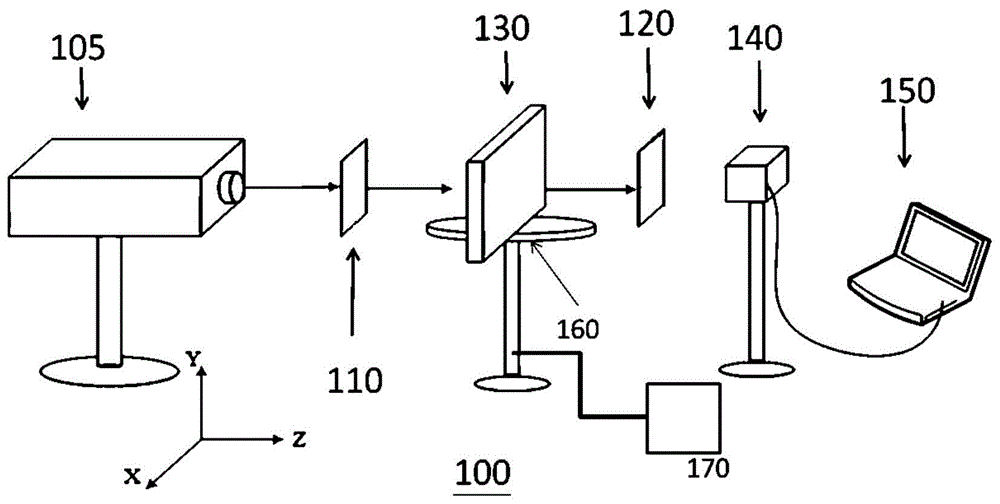
图1系为根据本发明一实施例的光学环境振荡侦测系统的示意图。FIG. 1 is a schematic diagram of an optical environmental oscillation detection system according to an embodiment of the present invention.
图2系为光线射入液晶元件之示意图。Fig. 2 is a schematic diagram of light entering a liquid crystal element.
图3为非寻常光模式下向量的计算的示意图。Fig. 3 is a schematic diagram of vector calculation in an extraordinary light mode.
图4为寻常光模式下向量的计算的示意图。Fig. 4 is a schematic diagram of vector calculation in ordinary light mode.
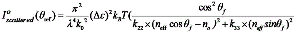
图5系根据本发明一实施例激光光束之传递方式寻常光模式时散射光之量测之示意图。FIG. 5 is a schematic diagram of the measurement of scattered light in the ordinary light mode of the transmission mode of the laser beam according to an embodiment of the present invention.
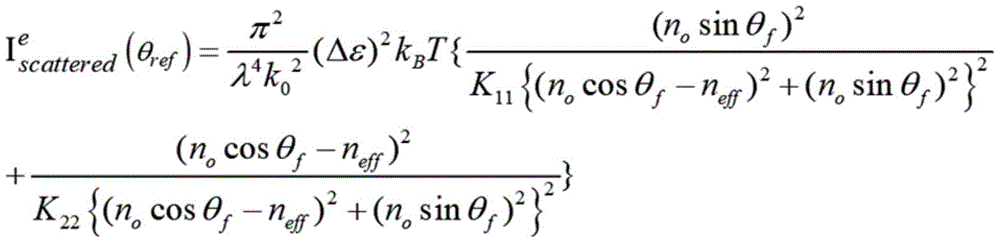
图6系根据本发明一实施例激光光束之传递方式为非寻常光模式时散射光之量测之示意图。FIG. 6 is a schematic diagram of measurement of scattered light when the transmission mode of the laser beam is an extraordinary light mode according to an embodiment of the present invention.
图7系为实际运用本发明之量测结果来进行环境振荡因子扣除的曲线图。FIG. 7 is a graph showing the deduction of environmental oscillation factors by actually using the measurement results of the present invention.
图8系为将图1之光学环境振荡侦测系统附接至量测仪器的示意图。FIG. 8 is a schematic diagram of attaching the optical environmental oscillation detection system of FIG. 1 to a measuring instrument.
图9系为图8之对量测仪器的量测数据进行干扰源校正的示意图。FIG. 9 is a schematic diagram of performing interference source correction on the measurement data of the measuring instrument in FIG. 8 .
图10系为根据本发明的一实施例光学量测方法的流程图。FIG. 10 is a flowchart of an optical measurement method according to an embodiment of the present invention.
附图标记:Reference signs:
100...激光光源100...laser light source
110...起偏片110...Polarizer
120...检偏片120...Analyzer
130...液晶元件130...LCD element
140...光学传感器140...optical sensors
150...计算机150...Computer
160...平台160...platform
170...控制器170...controller
131...入射光131...incident light
132...偏射光132...Polarized light
135...液晶135...LCD
θglass...玻璃夹角θ glass ... glass angle
θp...预倾角θ p ... pretilt angle
θref...最终偏折角θ ref ... final deflection angle
θrotation...转角θ rotation ... rotation angle
neff...等效折射率n eff ... equivalent refractive index
ne...非寻常光模式下的折射率n e ... the index of refraction in the extraordinary mode of light
no...寻常光模式下的折射率n o ...refractive index in ordinary light mode
I,q,f,kin,kout...向量I, q, f, k in , k out ... vector
q//...水平方位向量q // ...horizontal orientation vector
q⊥...垂直方位向量q ⊥ ... vertical orientation vector
dσ、dΩ、k0...参数dσ, dΩ, k 0 ... parameters
θref...折射角度θ ref ... angle of refraction
ε...介电常数ε...Dielectric constant
k0...波兹曼常数k 0 ...Boltzmann's constant
T...温度T...Temperature
K11...第一系数K 11 ... first coefficient
K22...扭曲形变弹性系数K 22 ...Elastic coefficient for torsional deformation
k33...弯折形变弹性系数k 33 ... elastic coefficient of bending deformation
neff...有效折射率n eff ... effective refractive index
θf...最终偏折角θ f ... final deflection angle
kB...波兹曼常数k B ... Boltzmann's constant
λ...散射光波长λ...wavelength of scattered light
n0...介质折射率n 0 ... medium refractive index
具体实施方式Detailed ways
揭露特别以下述例子加以描述,这些例子仅系用以举例说明而已,因为对于熟习此技艺者而言,在不脱离本揭示内容之精神和范围内,当可作各种之更动与润饰,因此本揭示内容之保护范围当视后附之权利要求所界定者为准。在通篇说明书与权利要求中,除非内容清楚指定,否则“一”以及“该”的意义包含这一类叙述包含“一或至少一”该元件或成分。此外,如本揭露所用,除非从特定上下文明显可见将复数个排除在外,否则单数冠词亦包含复数个元件或成分的叙述。而且,应用在此描述中与下述之全部权利要求中时,除非内容清楚指定,否则“在其中”的意思可包含“在其中”与“在其上”。在通篇说明书与权利要求所使用之用词(terms),除有特别注明,通常具有每个用词使用在此领域中、在此揭露之内容中与特殊内容中的平常意义。某些用以描述本揭露之用词将于下或在此说明书的别处讨论,以提供从业人员(practitioner)在有关本揭露之描述上额外的引导。在通篇说明书之任何地方之例子,包含在此所讨论之任何用词之例子的使用,仅系用以举例说明,当然不限制本揭露或任何例示用词之范围与意义。同样地,本揭露并不限于此说明书中所提出之各种实施例。The disclosure is particularly described with the following examples, which are for illustration only, since various changes and modifications may be made by those skilled in the art without departing from the spirit and scope of the disclosure, Therefore, the scope of protection of the disclosure should be defined by the appended claims. Throughout the specification and claims, unless the content clearly dictates otherwise, the meaning of "a" and "the" includes such references including "one or at least one" of that element or component. Furthermore, as used in the present disclosure, singular articles also include descriptions of plural elements or components, unless it is obvious from the specific context that the plural is excluded. Furthermore, as applied in this description and all the claims that follow, the meaning of "in" may include "in" and "on" unless the content clearly dictates otherwise. The terms used throughout the specification and claims, unless otherwise noted, generally have the ordinary meaning that each term has as used in the art, in this disclosure, and in the specific context. Certain terms used to describe the disclosure are discussed below or elsewhere in this specification to provide practitioners with additional guidance in describing the disclosure. The use of examples anywhere throughout the specification, including examples of any terms discussed herein, is for illustration only and certainly does not limit the scope and meaning of the disclosure or any exemplified term. Likewise, the present disclosure is not limited to the various embodiments presented in this specification.
在此所使用的用词“实质上(substantially)”、“大约(around)”、“约(about)”或“近乎(approximately)”应大体上意味在给定值或误差范围在20%以内,优选系在10%以内。此外,在此所提供之数量可为近似的,因此意味着若无特别陈述,可用词“大约”、“约”或“近乎”加以表示。当一数量、浓度或其他数值或参数有指定的范围、优选范围或表列出上下理想值之时,应视为特别揭露由任何上下限之数对或理想值所构成的所有范围,不论该等范围是否分别揭露。举例而言,如揭露范围某长度为X公分到Y公分,应视为揭露长度为H公分且H可为X到Y之间之任意实数。As used herein, the words "substantially", "around", "about" or "approximately" shall generally mean within 20% of a given value or error range , preferably within 10%. Furthermore, quantities provided herein may be approximate, thus meaning that the words "about", "about" or "approximately" may be used unless otherwise stated. Where a quantity, concentration, or other value or parameter has a specified range, preferred range, or tabulated upper and lower ideal values, it shall be deemed to specifically disclose all ranges formed by any pair of upper and lower limits or ideal values, regardless of the Whether the ranges are disclosed separately. For example, if a certain length of the disclosed range is X centimeters to Y centimeters, it should be deemed that the disclosed length is H centimeters and H can be any real number between X and Y.
此外,若使用“电(性)耦接”或“电(性)连接”一词在此系包含任何直接及间接的电气连接手段。举例而言,若文中描述一第一装置电性耦接于一第二装置,则代表该第一装置可直接连接于该第二装置,或通过其他装置或连接手段间接地连接至该第二装置。另外,若描述关于电讯号之传输、提供,熟习此技艺者应该可了解电讯号之传递过程中可能伴随衰减或其他非理想性之变化,但电讯号传输或提供之来源与接收端若无特别叙明,实质上应视为同一讯号。举例而言,若由电子电路之端点A传输(或提供)电讯号S给电子电路之端点B,其中可能经过一电晶体开关之源汲极两端及/或可能之杂散电容而产生电压降,但此设计之目的若非刻意使用传输时产生之衰减或其他非理想性之变化而达到某些特定的技术效果,电讯号S在电子电路之端点A与端点B应可视为实质上为同一讯号。In addition, if the term "electrical (sexual) coupling" or "electrical (sexual) connection" is used herein, it includes any direct and indirect electrical connection means. For example, if it is described that a first device is electrically coupled to a second device, it means that the first device can be directly connected to the second device, or indirectly connected to the second device through other devices or connection means. device. In addition, if you describe the transmission and provision of electrical signals, those familiar with the art should be able to understand that the transmission of electrical signals may be accompanied by attenuation or other non-ideal changes, but if the source and receiver of electrical signal transmission or provision are not special In essence, it should be regarded as the same signal. For example, if an electrical signal S is transmitted (or provided) from terminal A of the electronic circuit to terminal B of the electronic circuit, a voltage may be generated across the source and drain terminals of a transistor switch and/or possible stray capacitance However, if the purpose of this design is not to deliberately use the attenuation or other non-ideal changes generated during transmission to achieve certain specific technical effects, the electrical signal S at the terminal A and terminal B of the electronic circuit should be regarded as substantially same signal.
可了解如在此所使用的用词“包含(comprising)”、“包含(including)”、“具有(having)”、“含有(containing)”、“包含(involving)”等等,为开放性的(open-ended),即意指包含但不限于。另外,本发明的任一实施例或权利要求不须达成本发明所揭露之全部目的或优点或特点。此外,摘要部分和标题仅是用来辅助专利文件搜寻之用,并非用来限制本发明之权利要求。It will be appreciated that the terms "comprising," "including," "having," "containing," "involving," etc., as used herein, are open-ended The (open-ended) means including but not limited to. In addition, any embodiment or claims of the present invention need not achieve all the objects or advantages or features disclosed in the present invention. In addition, the abstract and titles are only used to assist patent document search, and are not used to limit the claims of the present invention.
本发明的主要目的在于检测液晶面板的漏光状态,设计可排除环境扰动因子的量测仪器来提升量测精准度。此发明为使用纯光学方式,利用液晶本身指向性扰动特性,只需简单光学物件:倾斜均匀配向(Tilted homogeneous alignment,THA)液晶元件、激光光、偏振片以及光学传感器,即可实现环境振荡量测,再结合其他精密光学量测仪器(如ZygoDynafiz、半导体精密光学量测仪器等等)进行环境振荡因子的扣除,即可实现一台高精准度之环境振荡测量设备,以提高光学对象之品质。环境振荡因子的扣除可包含干扰源校正,当中又包含调整液晶元件对应的扭转角、间隙及预倾角。环境振荡量测结果可结合与高精密量测设备量测结果来进行后处理,以消除环境振荡之影响,进而提升量测数据的真实性与稳定性。其中,液晶在暗态散色光之光强度,随着给电压后液晶旋转,其预倾角呈现线性递减,而预倾角之变动,会与环境振荡有正相关。本发明利用液晶本身指向性扰动,光轴会因环境振荡造成扰动现象,因此可利用已导出THA液晶暗态下光散射强度公式非寻常光模式(Extraordinary light mode,简称e-mode)和寻常光模式(Ordinary light mode,简称o-mode)进行分析环境振荡。液晶光轴经由环境微扰动,会造成预倾角(pretilt angle)的动态扰动变异,此动态变异可由光学传感器进行量测和分析。倾斜均匀配向液晶可以为水平配向(Horizontal alignment,HA)或垂直配向(Vertical alignment,VA),其中采用垂直配向液晶对环境振荡仪有较高精准性。The main purpose of the present invention is to detect the light leakage state of the liquid crystal panel, and design a measuring instrument capable of eliminating environmental disturbance factors to improve measurement accuracy. This invention uses a purely optical method and utilizes the directivity disturbance characteristics of liquid crystal itself. It only needs simple optical objects: Tilted homogeneous alignment (THA) liquid crystal element, laser light, polarizer and optical sensor to realize the environmental oscillation quantity. Combined with other precision optical measurement instruments (such as ZygoDynafiz, semiconductor precision optical measurement instruments, etc.) to deduct the environmental oscillation factor, a high-precision environmental oscillation measurement equipment can be realized to improve the quality of optical objects . The deduction of the environmental oscillation factor may include the correction of the interference source, which also includes adjusting the corresponding twist angle, gap and pretilt angle of the liquid crystal element. The measurement results of environmental vibration can be combined with the measurement results of high-precision measuring equipment for post-processing to eliminate the influence of environmental vibration, thereby improving the authenticity and stability of the measurement data. Among them, the light intensity of the scattered light of the liquid crystal in the dark state, as the liquid crystal rotates after the voltage is applied, the pre-tilt angle decreases linearly, and the change of the pre-tilt angle will have a positive correlation with the environmental oscillation. The invention utilizes the directivity disturbance of the liquid crystal itself, and the optical axis will be disturbed by the environment oscillation, so the extraordinary light mode (Extraordinary light mode, referred to as e-mode) and ordinary light mode (Extraordinary light mode, referred to as e-mode) and ordinary light Ordinary light mode (o-mode for short) is used to analyze environmental oscillations. The micro-disturbance of the optical axis of the liquid crystal through the environment will cause a dynamic disturbance variation of the pretilt angle, which can be measured and analyzed by the optical sensor. The oblique homogeneously aligned liquid crystals can be horizontally aligned (Horizontal alignment, HA) or vertically aligned (Vertical alignment, VA), wherein the use of vertically aligned liquid crystals has higher accuracy for ambient oscillators.
请参考图1,图1系为根据本发明一实施例的光学环境振荡侦测系统100的示意图。如图1所示,光学环境振荡侦测系统100包含一激光光源105、偏振轴相互垂直之起偏片110与检偏片120、一倾斜均匀配向(Tilted homogeneous alignment,THA)液晶元件130、一光学传感器140、一分析装置150、一平台160以及一控制器170,其中激光光源105用以提供高稳定之光源,光学传感器140用以侦测指向性散射光强度,分析装置150用于分析所量测之指向性扰动光强度。液晶在暗态散色光之光强度会随着液晶与基板夹角的增大而呈现线性递减,而液晶夹角之变动会与环境振荡有正相关,因此可以通过光强度之变化量来反推环境振荡因子。在本实施例中,分析装置150例如为一计算机,且为方便说明,以下称计算机150。此外,在另一未绘示的实施例中,分析装置150可为一云端服务器或手机、平板等手持式电子装置,皆不以此为限。Please refer to FIG. 1 , which is a schematic diagram of an optical environmental
此外,上述“均匀”是指每层液晶配向有相同之预倾角;另外,液晶分子之散射光有去极化之现象,且散射光大小会与预倾角以及环境振荡相关。激光光源105用以提供具有特定范围之波长之激光光束,举例来说,可为各种可见激光光,其波长优选介于400~780nm,例如633nm。液晶元件130的液晶光轴具有指向性扰动特性;起偏片110系置于激光光源105以及液晶元件130之间,起偏片110的偏光轴平行于一第一轴向。光学传感器140用以侦测液晶元件130处于暗态(dark mode)下的指向性扰动光强度。图1系将光行进的方向定义为Z轴方向、垂直方向定义为Y轴方向、水平方向则定义为X轴方向。起偏片110与检偏片120为相互垂直,在暗态下入射光无法穿透检偏片120;激光光通过液晶产生的散射光之偏振方向会与入射光相互垂直,因此散射光可穿透检偏片,并由光学传感器140接收暗态散色光之光强度,光强度系指单位时间、单位面积下接受到的光子数目。随着液晶与基板夹角,呈现线性递减,而液夹角之变动,会与环境振荡有正相关,因此可以通过光强度之变化量来反推环境振荡因子。In addition, the above-mentioned "uniform" means that each layer of liquid crystal alignment has the same pretilt angle; in addition, the scattered light of liquid crystal molecules has a depolarization phenomenon, and the magnitude of scattered light will be related to the pretilt angle and environmental oscillation. The
平台160可为一旋转加热平台,可根据其耦接之控制器170来进行旋转、加热等操作,加热的目的是为了控制温度,使得量测更加准确。The
液晶元件130在光传递方式为非寻常光模式(Extraordinary light mode)或是寻常光模式(Ordinary light mode)架构下,可推导任意斜向入射光经过液晶元件130之指向扰动方程式。根据本发明一实施例,液晶元件采用垂直配置(Vertical alignment,VA);根据本发明另一实施例,液晶元件采用水平配置(Horizontal alignment,HA);根据本发明另一实施例,液晶元件在暗态下之散射光强度随着其内之液晶单元的角度变化呈现线性递减。采用垂直配置的原因是因其预倾角最大;预倾角愈小则量测浮动较大,其中垂直配置的预倾角为90度,且水平配置的预倾角为0度。When the light transmission mode of the
在未有环境扰动下液晶元件130配向具有原始预倾角,在暗态环境(因为要检查漏光)下量测,激光光通过液晶元件130及两偏振片可以得到第一散射光强度;当有环境扰动情况下,液晶元件130配向的预倾角角度改变而具有改变的预倾角,激光光通过液晶元件130及两偏振片可以得到第二散射光强度。The alignment of the
请参考图2,图2系为光线射入液晶元件130之示意图,玻璃夹角θglass(入射光131与法线的夹角,法线在图中以虚线表示)、液晶135的预倾角θp(或称θpretilt)、最终偏折角θref(或称θrefraction,偏射光132与法线的夹角)可根据以下公式(1)、(2)得出(其中θrotation系为转角):Please refer to FIG. 2. FIG. 2 is a schematic diagram of light entering the
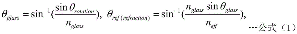
θf=|θp(pretilt)-θref|,…公式(2)θ f =|θ p(pretilt) -θ ref |,...Formula (2)
等效折射率neff可根据以下公式(3)得出:The equivalent refractive index n eff can be obtained according to the following formula (3):
neff=(cos2θf/ne 2+sin2θf/no 2)-0.5…(3)n eff =(cos 2 θ f /n e 2 +sin 2 θ f /n o 2 ) -0.5 …(3)
其中ne、no分别为非寻常光模式、寻常光模式下的折射率。Among them, ne and n o are the refractive indices in the extraordinary light mode and the ordinary light mode, respectively.
请一并参见图3、图4,其分别为非寻常光模式(e-mode)、寻常光模式(o-mode)下的i向量、f向量以及q向量的计算的示意图,其中非寻常光模式下的q向量可根据公式(4)求得:Please refer to Figure 3 and Figure 4 together, which are schematic diagrams of the calculation of i vector, f vector and q vector in the extraordinary light mode (e-mode) and ordinary light mode (o-mode), in which the extraordinary light The q vector in the mode can be obtained according to formula (4):
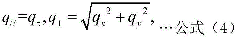
其中q//系为q的水平方位向量,且q⊥系为q的垂直方位向量,起偏片的轴向在非寻常光模式下与液晶光轴(长轴)相互平行,起偏片的轴向在寻常光模式下与液晶光轴相互垂直。Where q // is the horizontal azimuth vector of q, and q ⊥ is the vertical azimuth vector of q, the axial direction of the polarizer is parallel to the optical axis (major axis) of the liquid crystal in the extraordinary light mode, and the polarizer’s The axis is perpendicular to the optical axis of the liquid crystal in ordinary light mode.
寻常光模式下的q向量、等效k向量keff可分别根据公式(5)、(6)求得:The q vector and the equivalent k vector k eff in the ordinary light mode can be obtained according to formulas (5) and (6):
q//=k0(neffsinθf),q⊥=k0(neffcosθf-nO)…公式(5)q // =k 0 (n eff sinθ f ),q ⊥ =k 0 (n eff cosθ f -n O )…formula (5)

最后,THA液晶暗态下光散射强度可根据公式(7)求得:Finally, the light scattering intensity of the THA liquid crystal in the dark state can be obtained according to formula (7):

其中参数dσ的单位为输出功率除以实体角度(Powerout/solid angle)、参数dΩ(Powerin/unit area of incident beam)的单位为输入功率除以单位面积的入射光。综上,可得到i向量、f向量、q向量与X、Y、Z三轴的对照关系,如表(1)所示。The unit of the parameter dσ is the output power divided by the solid angle (Power out /solid angle), and the unit of the parameter dΩ (Power in /unit area of incident beam) is the input power divided by the incident light per unit area. To sum up, the contrastive relationship between the i vector, the f vector, and the q vector and the X, Y, and Z axes can be obtained, as shown in Table (1).
表(1)Table 1)
表(2)列举了非寻常光模式、寻常光模式下的折射指针(Refractive Index)ne和no、波长、弹力常数之间的对照关系。Table (2) lists the comparative relationship between the extraordinary light mode and the refraction index (Refractive Index) n e and no , wavelength, and elastic constant in the ordinary light mode.

表(2)Table 2)
参考图5,图5系根据本发明一实施例之寻常光模式(Ordinary light mode)时散射光之量测之示意图。在本实施例中,起偏片110(又称起偏片)的偏光轴系平行于Y轴、检偏片120(又称检偏片)之偏光轴系平行于X轴,用以进行寻常光模式下非激光光的量测,液晶元件(在图5中以“THALC”表示)在暗态以及寻常光模式下的散射光强度符合公式(8):Referring to FIG. 5 , FIG. 5 is a schematic diagram of measurement of scattered light in ordinary light mode according to an embodiment of the present invention. In this embodiment, the polarization axis of the polarizer 110 (also known as the polarizer) is parallel to the Y-axis, and the polarization axis of the analyzer 120 (also known as the analyzer) is parallel to the X-axis, for ordinary For the measurement of non-laser light in the light mode, the scattered light intensity of the liquid crystal element (indicated by "THALC" in Figure 5) in the dark state and ordinary light mode conforms to the formula (8):

其中
通过光学传感器140的量测以及计算机150套用上述公式(1)作运算,可得出液晶元件在暗态以及寻常光模式下的散射光强度,有了这样的信息,可搭配精密仪器诸如ZygoDynafiz(ZYGO DynaFizTM所出产的激光干涉仪)进行环境振荡分析,进行环境振荡过滤排除以提供仪器精准度与可靠度。Through the measurement of the
参考图6,图6系根据本发明一实施例激光光束之传递方式为非寻常光模式(Extraordinary light mode)时散射光之量测之示意图。在本实施例中,起偏片110的偏光轴系平行于X轴、检偏片120之偏光轴系平行于Y轴,用以进行激光光束之传递方式为寻常光模式(Ordinary light mode)下的量测,液晶元件(在图6中以“THALC”表示)在暗态以及寻常光模式下的散射光强度符合公式(9):Referring to FIG. 6 , FIG. 6 is a schematic diagram of measurement of scattered light when the transmission mode of the laser beam is an extraordinary light mode (Extraordinary light mode) according to an embodiment of the present invention. In this embodiment, the polarization axis of the

其中
参见图7,图7系为实际运用本发明之量测结果来进行环境振荡因子扣除的曲线图,其中纵轴代表漏光量(单位为μW),横轴代表施加的电压(单位为伏特)。如曲线所示,校正后数据即校正前数据减去漏光的成份,其中以“□”表示的曲线代表校正前数据、以“△”表示的曲线代表校正后数据、以“○”表示的曲线代表环境因子。由图7可得知采用本发明进行校正后可消除环境造成的影响,而大幅改善漏光量。Referring to FIG. 7, FIG. 7 is a graph showing the deduction of the environmental oscillation factor by actually using the measurement results of the present invention, wherein the vertical axis represents the amount of light leakage (in μW), and the horizontal axis represents the applied voltage (in volts). As shown in the curve, the corrected data is the pre-corrected data minus the component of light leakage, where the curve represented by "□" represents the data before correction, the curve represented by "△" represents the data after correction, and the curve represented by "○" represent environmental factors. It can be known from FIG. 7 that the influence of the environment can be eliminated after correction by the present invention, and the amount of light leakage can be greatly improved.
图8系为将图1之光学环境振荡侦测系统附接至量测仪器的示意图。请参考图1及图8,图1之光学环境振荡侦测系统100可附接至一量测仪器(例如为精密量测仪器50)。举例来说,可由分析装置150进一步耦接于精密量测仪器50,使得精密量测仪器50从分析装置150接收环境振荡因子。图9系为图8之对量测仪器的量测数据进行干扰源校正的示意图。请参考图8及图9,可对精密量测仪器50的一精密量测数据R1扣除从光学环境振荡侦测系统100接收的环境振荡因子R2,而获得精密量测数据R3。藉此,可进行干扰源校正。干扰源可包含:空气间因热膨胀的微扰动、空气流动、声波干扰、操作员走动、机台元件之作动干扰等等。FIG. 8 is a schematic diagram of attaching the optical environmental oscillation detection system of FIG. 1 to a measuring instrument. Please refer to FIG. 1 and FIG. 8 , the optical environmental
请参考图10,图10系为根据本发明的一实施例光学量测方法的流程图。请注意,假若可获得实质上相同的结果,则这些步骤并不一定要遵照图10所示的执行次序来执行。图10所示之方法可应用于图8所示之光学环境振荡侦测系统100以及量测仪器50,并可简单归纳如下:Please refer to FIG. 10 , which is a flowchart of an optical measurement method according to an embodiment of the present invention. Please note that these steps do not have to be performed in the order shown in FIG. 10 if substantially the same result can be obtained. The method shown in FIG. 10 can be applied to the optical environmental
步骤1002:通过一激光光源,在暗态下提供一激光光束;Step 1002: Provide a laser beam in a dark state through a laser light source;
步骤1004:通过一起偏片,自激光光源接收激光光束并输出,其中起偏片的偏光轴平行于一第一轴向;Step 1004: Receive and output the laser beam from the laser light source through a polarizer, wherein the polarization axis of the polarizer is parallel to a first axis;
步骤1006:通过一液晶元件,自起偏片接收激光光束并输出;Step 1006: receiving and outputting the laser beam from the polarizer through a liquid crystal element;
步骤1008:通过一检偏片,自液晶元件接收激光光束并输出,其中检偏片的偏光轴平行于一第二轴向,第二轴向垂直于第一轴向;Step 1008: Receive and output the laser beam from the liquid crystal element through an analyzer, wherein the polarization axis of the analyzer is parallel to a second axis, and the second axis is perpendicular to the first axis;
步骤1010:通过一光学传感器,自检偏片接收激光光束;Step 1010: through an optical sensor, the self-inspection polarizer receives the laser beam;
步骤1012:通过光学传感器,量测未有一环境扰动的一第一散射光强度,或量测有环境扰动的一第二散射光强度;Step 1012: Using the optical sensor, measure a first scattered light intensity without an environmental disturbance, or measure a second scattered light intensity with an environmental disturbance;
步骤1014:通过一分析装置,根据第一散射光强度与第二散射光强度的变化计算一环境振荡因子;以及Step 1014: Using an analysis device, calculate an environmental oscillation factor according to the change of the first scattered light intensity and the second scattered light intensity; and
步骤1016:对一量测仪器的一量测数据扣除环境振荡因子,而进行干扰源校正。Step 1016 : Subtract the environmental oscillation factor from a measurement data of a measurement instrument to perform interference source correction.
综上所述,本发明可在非寻常光模式下令起偏片与液晶光轴相互平行,以及可在寻常光模式下令起偏片与液晶光轴相互垂直,并且搭配各自对应的指向扰动方程式进行量测分析,并且根据量测分析结果进行环境振荡分析,并把此分析数据回传于高精密量测设备,以进行环境振荡过滤排除,提供仪器精准度与可靠度。此外,本发明系采用纯光学方式,利用液晶本身指向性扰动特性来实现环境振荡仪,故只需简单的光学对象(诸如液晶元件130、激光光源105、起偏片110、检偏片120以及光学传感器140)即可完成。由于无须设置昂贵的设备,本发明实具有成本上的优势。将本发明结合高精密量测设备,由于能够提供环境振荡因子讯号,可使高精密量测设备去除环境振荡之影响,提升量测数据的真实性与稳定性。In summary, the present invention can make the optical axis of the polarizer and the liquid crystal parallel to each other in the extraordinary light mode, and can make the optical axis of the polarizer and the liquid crystal perpendicular to each other in the ordinary light mode, and can be carried out with the corresponding pointing perturbation equations. Measurement and analysis, and environmental vibration analysis based on the measurement and analysis results, and the analysis data is sent back to high-precision measurement equipment to filter and eliminate environmental vibrations to provide instrument accuracy and reliability. In addition, the present invention adopts a purely optical method and utilizes the directivity disturbance characteristic of the liquid crystal itself to realize the environmental oscillator, so only simple optical objects (such as the
Claims (16)


Priority Applications (3)
| Application Number | Priority Date | Filing Date | Title |
|---|---|---|---|
| CN202110068462.7A CN112880803B (en) | 2021-01-19 | 2021-01-19 | Optical environment oscillation detection system and optical measurement method using same |
| TW110102341A TWI799784B (en) | 2021-01-19 | 2021-01-21 | Optical environmental oscillation detecting system and optical measuring method using the same |
| US17/186,634 US11829013B2 (en) | 2021-01-19 | 2021-02-26 | Optical environmental oscillation detecting system and optical measuring method using the same |
Applications Claiming Priority (1)
| Application Number | Priority Date | Filing Date | Title |
|---|---|---|---|
| CN202110068462.7A CN112880803B (en) | 2021-01-19 | 2021-01-19 | Optical environment oscillation detection system and optical measurement method using same |
Publications (2)
| Publication Number | Publication Date |
|---|---|
| CN112880803A CN112880803A (en) | 2021-06-01 |
| CN112880803B true CN112880803B (en) | 2022-11-22 |
Family
ID=76049686
Family Applications (1)
| Application Number | Title | Priority Date | Filing Date |
|---|---|---|---|
| CN202110068462.7A Active CN112880803B (en) | 2021-01-19 | 2021-01-19 | Optical environment oscillation detection system and optical measurement method using same |
Country Status (3)
| Country | Link |
|---|---|
| US (1) | US11829013B2 (en) |
| CN (1) | CN112880803B (en) |
| TW (1) | TWI799784B (en) |
Families Citing this family (1)
| Publication number | Priority date | Publication date | Assignee | Title |
|---|---|---|---|---|
| TWI797010B (en) * | 2022-04-28 | 2023-03-21 | 大陸商業成科技(成都)有限公司 | Curved optic structure and method of manufacturing thereof |
Citations (22)
| Publication number | Priority date | Publication date | Assignee | Title |
|---|---|---|---|---|
| SU419739A1 (en) * | 1972-02-24 | 1974-03-15 | И. Г. Чист ков, Л. К. Вистинь , И. Г. Горина | MECHANOPTRONV PT, *. Lindens n -; ^ - GP "r ^ FD?! ^ I; -: ^; -.: - ^^^ i |
| US3831434A (en) * | 1972-03-23 | 1974-08-27 | Vari Light Corp | Methods and apparatus for image display of sound waves and utilizations thereof |
| JPS62298727A (en) * | 1986-06-19 | 1987-12-25 | Asahi Glass Co Ltd | Vibration analysis device |
| US5131748A (en) * | 1991-06-10 | 1992-07-21 | Monchalin Jean Pierre | Broadband optical detection of transient motion from a scattering surface by two-wave mixing in a photorefractive crystal |
| US5335210A (en) * | 1992-10-28 | 1994-08-02 | The Charles Stark Draper Laboratory Inc. | Integrated liquid crystal acoustic transducer |
| CA2181306A1 (en) * | 1995-07-19 | 1997-01-20 | Charles Rheme | Method for the differential measurement of the angle of incidence of a luminous beam and device for implementing the method |
| AU2002212538A1 (en) * | 2000-11-07 | 2002-07-25 | Denny Bros Ltd | Booklet |
| JP2007049196A (en) * | 2006-10-27 | 2007-02-22 | National Institute Of Information & Communication Technology | Laser oscillation control method |
| WO2012161340A2 (en) * | 2011-05-26 | 2012-11-29 | Canon Kabushiki Kaisha | Acoustic wave receiving apparatus |
| CN104185794A (en) * | 2012-01-25 | 2014-12-03 | 新南方创新股份有限公司 | Optical based voltage sensing apparatus and method |
| WO2015071392A1 (en) * | 2013-11-18 | 2015-05-21 | Thales | Sensor with high-sensitivity optical fibre |
| CN104819769A (en) * | 2015-04-30 | 2015-08-05 | 杭州电子科技大学 | Vibration measurement apparatus based on laser speckle of polarized singular-point light beam |
| CN105043525A (en) * | 2015-04-30 | 2015-11-11 | 杭州电子科技大学 | Laser speckle-based vibration information detection method |
| CN105092877A (en) * | 2015-05-19 | 2015-11-25 | 南京师范大学 | Triangular wave phase modulation semiconductor laser self-mixing tachymeter and measuring method thereof |
| CN105258783A (en) * | 2015-11-16 | 2016-01-20 | 杭州电子科技大学 | Vibration detection method based on laser wavefront coding technique |
| WO2016150824A1 (en) * | 2015-03-23 | 2016-09-29 | Thales | Distributed optical fibre sensor for sensing stress state |
| JP2016176696A (en) * | 2015-03-18 | 2016-10-06 | 株式会社東芝 | Vibration measurement device |
| CN107421623A (en) * | 2017-05-11 | 2017-12-01 | 哈尔滨工程大学 | The piezoelectric ceramic type non-coherent optical fiber hydrophone and preparation method of integrated liquid crystal |
| CN108680768A (en) * | 2018-06-28 | 2018-10-19 | 北京理工大学 | A kind of method and apparatus of detection rotary body angular acceleration |
| CN111121970A (en) * | 2020-01-17 | 2020-05-08 | 业成科技(成都)有限公司 | Optical polarization state testing device and testing method thereof |
| CN111220274A (en) * | 2020-01-17 | 2020-06-02 | 业成科技(成都)有限公司 | Optical polarization state testing device and testing method thereof |
| CN111256828A (en) * | 2020-01-17 | 2020-06-09 | 业成科技(成都)有限公司 | Mechanism for measuring polarized light 3D image and manufacturing method thereof |
Family Cites Families (7)
| Publication number | Priority date | Publication date | Assignee | Title |
|---|---|---|---|---|
| US4379408A (en) * | 1981-01-12 | 1983-04-12 | Raj Technology Partnership | Liquid crystal technique for examining internal structures |
| DE69229298T2 (en) * | 1991-03-12 | 2000-02-03 | Fujitsu Ltd., Kawasaki | Liquid crystal display device |
| JP3910352B2 (en) * | 2000-04-11 | 2007-04-25 | 三菱電機株式会社 | Pretilt angle detection method and detection apparatus |
| GB0027213D0 (en) * | 2000-11-07 | 2000-12-27 | Denny Bros Printing | Booklet |
| TWI437220B (en) * | 2009-10-27 | 2014-05-11 | Ind Tech Res Inst | System and method for measuring pre-tilt angle of liquid crystal |
| FR3031590B1 (en) * | 2015-01-09 | 2017-01-13 | Thales Sa | FIBER OPTIC SENSOR |
| CN109856422B (en) * | 2019-02-19 | 2022-03-22 | 成都京东方光电科技有限公司 | Acceleration sensor, acceleration measuring device and method |
-
2021
- 2021-01-19 CN CN202110068462.7A patent/CN112880803B/en active Active
- 2021-01-21 TW TW110102341A patent/TWI799784B/en active
- 2021-02-26 US US17/186,634 patent/US11829013B2/en active Active
Patent Citations (22)
| Publication number | Priority date | Publication date | Assignee | Title |
|---|---|---|---|---|
| SU419739A1 (en) * | 1972-02-24 | 1974-03-15 | И. Г. Чист ков, Л. К. Вистинь , И. Г. Горина | MECHANOPTRONV PT, *. Lindens n -; ^ - GP "r ^ FD?! ^ I; -: ^; -.: - ^^^ i |
| US3831434A (en) * | 1972-03-23 | 1974-08-27 | Vari Light Corp | Methods and apparatus for image display of sound waves and utilizations thereof |
| JPS62298727A (en) * | 1986-06-19 | 1987-12-25 | Asahi Glass Co Ltd | Vibration analysis device |
| US5131748A (en) * | 1991-06-10 | 1992-07-21 | Monchalin Jean Pierre | Broadband optical detection of transient motion from a scattering surface by two-wave mixing in a photorefractive crystal |
| US5335210A (en) * | 1992-10-28 | 1994-08-02 | The Charles Stark Draper Laboratory Inc. | Integrated liquid crystal acoustic transducer |
| CA2181306A1 (en) * | 1995-07-19 | 1997-01-20 | Charles Rheme | Method for the differential measurement of the angle of incidence of a luminous beam and device for implementing the method |
| AU2002212538A1 (en) * | 2000-11-07 | 2002-07-25 | Denny Bros Ltd | Booklet |
| JP2007049196A (en) * | 2006-10-27 | 2007-02-22 | National Institute Of Information & Communication Technology | Laser oscillation control method |
| WO2012161340A2 (en) * | 2011-05-26 | 2012-11-29 | Canon Kabushiki Kaisha | Acoustic wave receiving apparatus |
| CN104185794A (en) * | 2012-01-25 | 2014-12-03 | 新南方创新股份有限公司 | Optical based voltage sensing apparatus and method |
| WO2015071392A1 (en) * | 2013-11-18 | 2015-05-21 | Thales | Sensor with high-sensitivity optical fibre |
| JP2016176696A (en) * | 2015-03-18 | 2016-10-06 | 株式会社東芝 | Vibration measurement device |
| WO2016150824A1 (en) * | 2015-03-23 | 2016-09-29 | Thales | Distributed optical fibre sensor for sensing stress state |
| CN104819769A (en) * | 2015-04-30 | 2015-08-05 | 杭州电子科技大学 | Vibration measurement apparatus based on laser speckle of polarized singular-point light beam |
| CN105043525A (en) * | 2015-04-30 | 2015-11-11 | 杭州电子科技大学 | Laser speckle-based vibration information detection method |
| CN105092877A (en) * | 2015-05-19 | 2015-11-25 | 南京师范大学 | Triangular wave phase modulation semiconductor laser self-mixing tachymeter and measuring method thereof |
| CN105258783A (en) * | 2015-11-16 | 2016-01-20 | 杭州电子科技大学 | Vibration detection method based on laser wavefront coding technique |
| CN107421623A (en) * | 2017-05-11 | 2017-12-01 | 哈尔滨工程大学 | The piezoelectric ceramic type non-coherent optical fiber hydrophone and preparation method of integrated liquid crystal |
| CN108680768A (en) * | 2018-06-28 | 2018-10-19 | 北京理工大学 | A kind of method and apparatus of detection rotary body angular acceleration |
| CN111121970A (en) * | 2020-01-17 | 2020-05-08 | 业成科技(成都)有限公司 | Optical polarization state testing device and testing method thereof |
| CN111220274A (en) * | 2020-01-17 | 2020-06-02 | 业成科技(成都)有限公司 | Optical polarization state testing device and testing method thereof |
| CN111256828A (en) * | 2020-01-17 | 2020-06-09 | 业成科技(成都)有限公司 | Mechanism for measuring polarized light 3D image and manufacturing method thereof |
Non-Patent Citations (1)
| Title |
|---|
| Entanglement-free determination of pretilt angles of twisted nematic liquid-crystal cells by phase measurement;姜哲文 等;《Chinese Optics Letters》;20171231;第15卷(第8期);62-65 * |
Also Published As
| Publication number | Publication date |
|---|---|
| CN112880803A (en) | 2021-06-01 |
| TW202229837A (en) | 2022-08-01 |
| US20220229319A1 (en) | 2022-07-21 |
| TWI799784B (en) | 2023-04-21 |
| US11829013B2 (en) | 2023-11-28 |
Similar Documents
| Publication | Publication Date | Title |
|---|---|---|
| Hidaka | Progress in Japan of space charge field measurement in gaseous dielectrics using a Pockels sensor | |
| TW477897B (en) | Liquid crystal display device, method and device to measure cell thickness of liquid crystal display device, and phase difference plate using the method thereof | |
| JP5599790B2 (en) | Method and apparatus for reducing optical interference and crosstalk of double optical tweezers using one laser light source | |
| JPH04332878A (en) | Electromagnetic field intensity measuring device | |
| Sima et al. | Temperature characteristics of Pockels electro-optic voltage sensor with double crystal compensation | |
| CN112880803B (en) | Optical environment oscillation detection system and optical measurement method using same | |
| CN1768258B (en) | Optical rotation measuring device | |
| Huang et al. | An optical glass plane angle measuring system with photoelectric autocollimator | |
| Faetti et al. | Strong azimuthal anchoring energy at a nematic-polyimide interface | |
| US5559442A (en) | Process and sensor for measuring electric voltages and/or electric field intensities | |
| CN116243218A (en) | An all-optical two-axis atomic magnetometer device and method based on optical frequency shift modulation | |
| Zhu et al. | High sensitive space electric field sensing based on micro fiber interferometer with field force driven gold nanofilm | |
| Tsuguhiro Takahashi et al. | New optical-waveguide pockels sensor for measuring electric fields | |
| Tretiakov et al. | Thermal imaging and conoscopic studies of working acousto-optical devices on the base of paratellurite | |
| JP6989852B2 (en) | Electric field sensor | |
| KR100606420B1 (en) | Detector insertion type photovoltage detector | |
| Gao et al. | Influencing factors and uncertainty analysis for Kerr electro-optic effect based electric field measurements in transformer oil under impulse voltage | |
| Wang et al. | Ultrasensitive optical electric field sensor based on harmonic vernier effect | |
| Miles et al. | Report on non-contact DC electric field sensors | |
| Vetrov et al. | A highly sensitive technique for measurements of the Kerr electrooptic coefficient in glasses and glass ceramics | |
| Li et al. | Research on supporting mounts of spheres in measurement of gravitational constant G | |
| US9824613B2 (en) | Liquid display panel and method for detecting electric potential generated by ions between liquid crystal layer and alignment film | |
| Lin et al. | High sensitivity two-frequency paired polarized interferometer in Faraday rotation angle measurement of ambient air with single-traveling configuration | |
| Xiao et al. | Electric field measurement using a three-photon double-dark-state model in Rydberg atoms | |
| Zhu et al. | Two-dimensional optical measurement techniques based on optical birefringence effects |
Legal Events
| Date | Code | Title | Description |
|---|---|---|---|
| PB01 | Publication | ||
| PB01 | Publication | ||
| SE01 | Entry into force of request for substantive examination | ||
| SE01 | Entry into force of request for substantive examination | ||
| GR01 | Patent grant | ||
| GR01 | Patent grant | ||
| TR01 | Transfer of patent right |
Effective date of registration: 20240109 Address after: 518109, Building E4, 101, Foxconn Industrial Park, No. 2 East Ring 2nd Road, Fukang Community, Longhua Street, Longhua District, Shenzhen City, Guangdong Province (formerly Building 1, 1st Floor, G2 District), H3, H1, and H7 factories in K2 District, North Shenchao Optoelectronic Technology Park, Minqing Road, Guangdong Province Patentee after: INTERFACE OPTOELECTRONICS (SHENZHEN) Co.,Ltd. Patentee after: Interface Technology (Chengdu) Co., Ltd. Patentee after: GENERAL INTERFACE SOLUTION Ltd. Address before: No.689 Hezuo Road, West District, high tech Zone, Chengdu City, Sichuan Province Patentee before: Interface Technology (Chengdu) Co., Ltd. Patentee before: INTERFACE OPTOELECTRONICS (SHENZHEN) Co.,Ltd. Patentee before: Yicheng Photoelectric (Wuxi) Co.,Ltd. Patentee before: GENERAL INTERFACE SOLUTION Ltd. |
|
| TR01 | Transfer of patent right |