Detailed Description
The foregoing summary, as well as the following detailed description of certain embodiments, will be better understood when read in conjunction with the appended drawings. As used herein, an element or step recited in the singular and proceeded with the word "a" or "an" should be understood as not necessarily excluding plural elements or steps. Furthermore, references to "one embodiment" are not intended to be interpreted as excluding the existence of additional embodiments that also incorporate the recited features. Furthermore, unless explicitly stated to the contrary, embodiments "comprising," "containing," "including," or "having" one or more elements having a particular condition may include additional elements not having that condition.
Certain embodiments of the subject disclosure provide systems and methods for presenting indicia (e.g., identifiers, indicators, etc.) of areas on an airport map. In at least one embodiment, the system and method include a map marking control unit configured to selectively present markings of an area of an airport on a site map. For example, a map marker control unit determines the presence and orientation of markers for an area of an airport map. These areas include buildings (such as terminal buildings, control towers, and hangars), runways, taxiways, docking stations, de-icing locations, tarmac, and the like.
In at least one embodiment, the map tag control unit determines different sets of tags that are displayed (e.g., shown on the display) for different views of the airport map. In at least one embodiment, the different views are different zoom levels of the airport map. The map tag control unit generates a complete set of tags for an area of the airport map for a plurality of zoom levels, such as a maximum zoom level, a 4km zoom level, a 2km zoom level, and a 1km zoom level. The zoom level is identified by the width of the airport map that fits into the fixed window of the display. In at least one embodiment, even though some features may be marked at multiple levels, the sets of marks for different zoom levels are independent of each other.
In at least one embodiment, a map tag control unit performs a series of steps to create a tag set for an airport. The map tagging control unit retrieves shape data from the airport map, then incorporates the geometry into other features, pre-processes (e.g., containerizes) the features, and then tags the area of each available zoom level of the airport map.
Certain embodiments of the subject disclosure provide a method comprising: generating, by a map tagging control unit, tagging candidates for an area of an airport map, and evaluating, by the map tagging control unit, the tagging candidates to determine a bearing for a tag of the area of the airport map.
Certain embodiments of the subject disclosure provide a system comprising a map tagging control unit configured to tag candidates for an area of an airport map and evaluate the tagged candidates to determine a bearing for tagging of the area of the airport map.
Certain embodiments of the subject disclosure provide a non-transitory computer-readable storage medium comprising executable instructions that, in response to execution, cause a map tagging control unit comprising a processor to perform operations comprising: generating a marker candidate for an area of the airport map, and evaluating the marker candidate to determine a bearing for a marker of the area of the airport map.
As described herein, embodiments of the subject disclosure provide systems and methods that greatly reduce the amount of time it takes for a mapping technician to modify the placement of markers for various airport areas on an airport map.
Fig. 1 illustrates a system 100 for marking an area on an airport map 102, according to an exemplary embodiment of the subject disclosure. The system 100 includes a map tagging control unit 104 in communication with a memory 106 storing an airport map 102, such as through one or more wired or wireless connections, and in communication with a user interface 108, such as through one or more wired or wireless connections. For example, the map tagging control unit 104 and the user interface 108 may include communication devices, such as antennas, transceivers, etc., that allow wireless communication therebetween. As another example, the map tagging control unit 104 and the user interface 108 may communicate through an intermediate medium (such as through the internet, a private communication network, etc.). In at least one embodiment, the memory 106 may be part of the map tagging control unit 104.
The map tagging control unit 104 may be located remotely from the memory 106 and the user interface 108, or may alternatively be co-located with the memory 106 and/or the user interface 108. For example, the map tagging control unit 104 and memory 106 may be located at a land-based surveillance location while the user interface 108 is on an aircraft. As another example, the map tagging control unit 104, the memory 106, and the user interface 108 may be located at a common location, such as within an aircraft traffic control tower, an aircraft, and so forth.
In at least one embodiment, the user interface 108 may be part of a flight computer of an aircraft. As another example, the user interface 108 may be part of a separate computer workstation on the aircraft. As another example, the user interface 108 may be a handheld device such as a smart phone, a table, etc., within an aircraft. As another example, the user interface 108 may be located remotely from the aircraft, such as at a flight planning center, an air traffic control tower, or the like.
The user interface 108 includes a display 110 and an input device 112, both of which may be in communication with the operation control unit. The display 110 may be a monitor, screen, television, touch screen, or the like. Input device 112 may include a keyboard, mouse, stylus, touch screen interface (i.e., input device 112 may be integrated with display 110), and so forth.
The airport map 102 provides a scaled representation of airports configured to be shown on the display 110. The airport map 102 includes geometric shapes (or reference geometries) that represent various areas of an airport. These areas include terminal buildings, runways, control towers, taxiways, tarmac, de-icing locations, parking stations near the terminal building gates, and the like. The geometry is associated with attributes (such as text) that identify the geometry as an area of an airport. For example, a geometric shape representing a terminal building is associated with an attribute such as the word "terminal building". The geometry and associated attributes of the airport map 102 are stored in memory 106. The airport map 102 includes data representing shapes, attributes, etc. that may be predefined. As described herein, the map tagging control unit 104 analyzes various underlying data of the airport map to generate tag candidates for display, evaluates the tag candidates to determine the orientation of the tags on the displayed version of the airport map 102, and determines a set of tags for different views of the airport map 102. The airport map 102, as well as the underlying data, may be received from a data source, such as a planning or architectural data store for the airport represented by the airport map 102. The airport map 102 and underlying data may be defined by a user, such as an airport definition represented by a planner, architect, engineer, etc. for the airport map 102. As described herein, the map tag control unit 104 determines the orientation of a tag (which is, includes, or is otherwise associated with at least a portion of an attribute) for the geometry of the airport map 102 as shown by the display 110.
The map tagging control unit 104 performs various operations and steps described herein. For example, the map tagging control unit 104 automatically generates tag candidates for areas of an airport map (e.g., buildings, taxiways, de-icing locations, landing pads, docking stations, tarmac, etc.) and evaluates the tag candidates to determine the bearings of the tags. In at least one embodiment, the map tag control unit 104 also generates a conflict graphic and resolves conflicts between tags of the airport map.
Fig. 2 shows a schematic block diagram of an example of the map tagging control unit 104, according to an embodiment of the subject disclosure. In at least one embodiment, the map tagging control unit 104 includes at least one processor 114 in communication with a memory 116. The memory 116 may include or may be the memory 106 shown in fig. 1. Alternatively, memory 116 may be separate and distinct from memory 106. Memory 116 stores instructions 118, received data 120, and generated data 122. The map marking control unit 104 shown in fig. 2 is merely exemplary and not limiting.
As used herein, the terms "control unit," "central processing unit," "CPU," "computer," and the like may include any processor-based or microprocessor-based system, including systems using microcontrollers, Reduced Instruction Set Computers (RISC), Application Specific Integrated Circuits (ASICs), logic circuits, and any other circuit or processor capable of executing the functions described herein, including hardware, software, or a combination thereof. This is merely exemplary and, as such, is not intended to limit the definition and/or meaning of such terms in any way. For example, as described herein, the map tagging control unit 104 may be or include one or more processors configured to control the operations thereof.
The map tagging control unit 104 is configured to execute a set of instructions stored in one or more data storage units or elements (such as one or more memories) in order to process the data. For example, the map tagging control unit 104 may include or be coupled to one or more memories. The data storage unit may also store data or other information as desired or needed. The data storage elements may be in the form of physical memory elements within the information source or processor. The one or more data storage units or elements may include volatile memory or non-volatile memory, or may include both volatile and non-volatile memory. By way of example, non-volatile memory can include read-only memory (ROM), programmable ROM (prom), electrically programmable ROM (eprom), electrically erasable prom (eeprom), and/or flash memory, and volatile memory can include Random Access Memory (RAM), which can serve as external cache memory. The data stores of the disclosed systems and methods are intended to comprise, without being limited to, these and any other suitable types of memory.
The set of instructions may include various commands that instruct the map tagging control unit 104 as a processing machine to perform certain operations, such as the methods and processes of various embodiments of the subject matter described herein. The set of instructions may be in the form of a software program. The software may be in various forms such as system software or application software. Further, the software may be in the form of a collection of separate programs, a subset of programs within a larger program, or a portion of a program. The software may also include modular programming in the form of object-oriented programming. The processing of input data by a processing machine may be in response to a user command, or in response to the results of a previous processing, or in response to a request made by another processing machine.
The illustrations of embodiments herein may show one or more control or processing units, such as a map tagging control unit 104. It should be understood that a processing or control unit may represent circuitry, or a portion thereof, which may be implemented as hardware (e.g., software stored on a tangible and non-transitory computer-readable storage medium, such as a computer hard drive, ROM, RAM, etc.) with associated instructions to perform the operations described herein. The hardware may include state machine circuitry that is hardwired to perform the functions described herein. Alternatively, the hardware may comprise electronic circuitry that includes and/or is connected to one or more logic-based devices, such as microprocessors, processors, controllers, and the like. Alternatively, the map marker control unit 104 may represent processing circuitry, such as one or more of a Field Programmable Gate Array (FPGA), an Application Specific Integrated Circuit (ASIC), microprocessor(s), or the like. The circuitry in various embodiments may be configured to execute one or more algorithms to perform the functions described herein. Whether or not explicitly identified in a flowchart or a method, one or more algorithms may comprise aspects of the embodiments disclosed herein.
As used herein, the terms "software" and "firmware" are interchangeable, and include any computer program stored in a data storage unit (e.g., one or more memories) for execution by a computer, including RAM memory, ROM memory, EPROM memory, EEPROM memory, and non-volatile RAM (nvram) memory. The above data storage unit types are exemplary only, and thus there is no limitation on the types of memory usable for storing computer programs.
FIG. 3 illustrates a flow chart of a method for marking an area on an airport map, according to an embodiment of the subject disclosure. In at least one embodiment, the airport map 102 includes data associated with predetermined indicia that are associated with geometric shapes. For example, a shape corresponding to a terminal building is associated with a marker for that terminal building. The markers and associated shapes may be user-defined, dynamically defined based on rules stored in memory, predetermined, and stored in memory 106 as data regarding the airport map 102. In at least one embodiment, referring to fig. 1-3, the method may be implemented at least in part by the map tagging control unit 104. At 130, marker candidates for an area of the airport map may be generated. At 132, the marker candidates may be evaluated to determine the location of the marker on the region, as described herein. At 134, a conflict graphic can be generated for the mark. At 136, conflicts between the tags may be resolved.
In at least one embodiment, the area on the airport map is a building (such as an airport terminal, control tower, hangar, etc.) of the airport as represented on the airport map. The map marking control unit 104 generates marking candidates for buildings on the airport map and evaluates the marking candidates for the buildings, thereby determining the orientations of the markings for the buildings on the airport map.
In at least one embodiment, the area on the airport map is a taxiway of the airport as represented on the airport map. The map marking control unit 104 generates marking candidates for taxiways on the airport map and evaluates the marking candidates for taxiways, thereby determining the orientations of the markings for taxiways on the airport map.
In at least one embodiment, the area on the airport map is a deicing location (such as a deicing pad and a deicing station) of the airport as represented on the airport map. The map marking control unit 104 generates marking candidates for the deicing positions on the airport map, and evaluates the marking candidates for the deicing positions, thereby determining the orientations of the markings for the deicing positions on the airport map.
In at least one embodiment, the area on the airport map is the landing pad of the airport as represented on the airport map. The map marking control unit 104 generates marking candidates for the landing pad on the airport map and evaluates the marking candidates for the landing pad in order to determine the bearing of the marking for the landing pad on the airport map.
In at least one embodiment, the area on the airport map is a docking station for the airport as represented on the airport map. The map marking control unit 104 generates marking candidates for a parking station on the airport map, and evaluates the marking candidates for the parking station, thereby determining the orientation of the marking for the parking station on the airport map.
In at least one embodiment, the area on the airport map is the apron of the airport as represented on the airport map. The map marking control unit 104 generates marking candidates for the apron on the airport map and evaluates the marking candidates for the apron to determine the bearing of the marking for the taxiways on the airport map.
FIG. 4 illustrates a display 110 showing an airport map 102 at a first zoom level, according to an embodiment of the subject disclosure. As an example, the first zoom level is a maximum zoom level that includes a vertical scale (scale) 150. The vertical scale 150 extends from the bottom 151 to the top 153 of the airport map 102, as shown on the display 110. The vertical scale 150 may indicate 5 kilometers (km). For example, the vertical scale 150 is 4.79 km.
The airport map 102 shows the geometry 152 of the terminal building and attributes 154 including the markers for that terminal building. The airport 102 also shows the geometry 152 of the control tower and hangar, as well as attributes including indicia for the control tower and hangar.
Referring to fig. 1 and 4, the map tag control unit 104 shows the overall layout of an airport (as shown in the airport map 102) with only tags for predetermined primary areas, such as terminal buildings, control towers and hangars. The designation of the main area is determined in advance and stored as part of the data of the airport map 102 stored in the memory 106.
All regions represented by geometric shapes 152 are marked. In at least one embodiment, the map marker control unit 104 prioritizes the area markers where the primary taxiways are of a first priority, the control tower is of a second priority less than the first priority, the terminal, lobby, and dock are of a third priority less than the second priority, and the other areas are of a fourth priority less than the third priority. The priority rules are stored in memory 106 or memory 116. The priority rules may be user defined. Such priorities are merely exemplary, and the map flag control unit 104 may reorder the priorities.
In at least one embodiment, a taxiway 156 is considered a primary taxiway if its length is greater than 20% of the taxiway and/or its area is greater than 30% of the maximum taxiway. The designation of primary and secondary taxiways and other areas on the airport map are predetermined and stored as part of the data of the airport map 102 as stored in the memory 106.
FIG. 5 illustrates a display 110 showing the airport map 102 at a second zoom level, according to an embodiment of the subject disclosure. The second zoom level is less than the first zoom level. For example, the vertical scale 150 at the second zoom level is 4 km. In the second zoom level, markers 155 for certain major taxiways, such as major taxiways B, C, D and E, are shown. Referring to fig. 1 and 5, at the second zoom level, the map tagging control unit 104 may tag major taxiways (such as major taxiways B, D, D and E), terminal buildings (such as terminal buildings 1 and 2), control towers, and runways.
FIG. 6 illustrates a display 110 showing the airport map 102 at a third zoom level, according to an embodiment of the subject disclosure. The third zoom level is less than the second zoom level. For example, the vertical scale 150 at the third zoom level is 2 km. In the third zoom level, markers 155 for all taxiways are shown, such as major taxiways J, K and L, and minor taxiways, such as J2, K1, and M1. Referring to fig. 1 and 6, at the third zoom level, the map marking control unit 104 may mark a major taxiway, a minor taxiway, a lobby of a terminal building, a control tower, a deicing area, and a hangar.
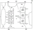
FIG. 7 illustrates a display 110 showing the airport map 102 at a fourth zoom level, according to an embodiment of the subject disclosure. The fourth zoom level is less than the third zoom level. For example, the vertical scale 150 at the fourth zoom level is 1 km. In a fourth zoom level, indicia (such as 40, 42, 46, etc.) for a docking station near a gate of the terminal building are shown. Referring to fig. 1 and 6, at a fourth zoom level, the map marking control unit 104 may mark all of the docking stations shown on the display 110.
Referring to fig. 1 and 4-7, the map marker control unit 104 determines different sets of markers that are displayed (e.g., shown on a display) for different views of the airport map 102. In at least one embodiment, the different views are different zoom levels of the airport map. For example, the map marker control unit 104 provides (e.g., shown on the airport map 102) a first marker for a first area at a first zoom level, a second marker for a second area at a second zoom level, a third marker for a third area at a third zoom level, and a fourth marker for a fourth area at a fourth zoom level. In at least one embodiment, the first areas at the first zoom level include major buildings, such as one or more terminal buildings, one or more hangars, and control towers (i.e., these first areas are marked at the first zoom level). The second region at the second zoom level includes the primary taxiways (i.e., marks all of the primary taxiways shown). A third region at a third zoom level includes all of the taxiways and deicing locations shown (i.e., all of the taxiways (whether primary or not) are marked and the deicing locations shown). The fourth zone at the fourth zoom level includes all of the illustrated docking stations (i.e., all of the docking stations indicated by the indicia).
The map tag control unit 104 creates a complete set of tags for a plurality of zoom levels, such as a first zoom level, a second zoom level, a third zoom level, and a fourth zoom level. With respect to a first zoom level, which may be considered a maximum zoom level, the map tagging control unit 104 tags (e.g., annotates with text) the selected building with a priority of (1) control tower; (2) terminal buildings, halls, docks; and (3) other large buildings. As an example, a building is considered large if its area is greater than 30% of the area of the largest building present in the airport map 102. The priority rules are stored in memory 106 and/or memory 116. The priority rules are predefined. For example, a user may define priority rules. In at least one embodiment, the map tag control unit 104 determines or selects a set of tags for different views of the airport map based on various criteria, including defined priorities, user-defined data, and the like.
With respect to the second zoom level, all buildings may be marked. The primary taxiway is added to the top of the priority list. For example, at the second zoom level, the map tagging control unit 104 tags the area based on the following priorities: (1) a main taxiway; (2) controlling the tower; (3) terminal buildings, lobbies and docks; and (4) other buildings.
With respect to the third zoom level, all buildings and all taxiways may be marked. De-icing areas and landing pad symbols are added. In the third zoom level, the non-primary taxiways (connectors) have the highest priority. For example, at the third zoom level, the map marking control unit 104 marks the area based on the following priorities: (1) a non-primary taxiway; (2) a main taxiway; (3) terminal buildings, halls, docks; (4) deicing locations (such as deicing pads); (5) other buildings, landing pads; and (6) controlling the column.
With respect to the fourth zoom level, all airport features are marked at that level (highest priority first). For example, at a fourth zoom level, the map tagging control unit 104 tags regions based on the following priorities: (1) a parking station; (2) parking apron; (3) taxiways (primary and non-primary, e.g., secondary); (4) terminal buildings, halls, docks; (5) a de-icing location; (6) other buildings, landing pads; and (7) controlling the column.
The map marking control unit 104 is also programmed to operate according to overlay rules, which are stored in a memory, such as the memory 106 shown in fig. 1 and/or the memory 116 shown in fig. 2. Overlapping rules include non-overlapping rules, which are defined as marks that do not overlap each other. An example of an exception to the non-overlapping rule is that the plateau symbols may overlap each other, such as to the extent of a triangular box around the "H" symbol. That is, the H symbols may not overlap. The building and tarmac markers cannot then overlap the runway geometry except for the control tower shown at the first zoom level. In addition, taxiway markers are remote from the runway, de-icing area, and taxiway waiting lines. "remote" is defined as allowing some overlap when no other method places the markers without overlap. In such a far-off situation, the overlap area cannot exceed half the area of the marks and the marks are placed in such a way that the overlap is minimal.
Referring again to fig. 1, the map tag control unit 104 performs a series of steps to create a tag collection for the airport map 102. Initially, the map tagging control unit 104 retrieves shape data (such as extracted from the airport map 102 stored in the memory 106), then incorporates the service road geometry into other features, then pre-processes (e.g., containerizes) the features, then tags each available zoom level for the airport map 102, which may then be written to an annotation file.
In at least one embodiment, the map tagging control unit 104 reads all shape files of the airport map 102 from a specified location (determined by a file extension). Shape file attributes and geometry are placed in airport objects. The old ann (i.e., annotation) file will be deleted before the process begins. All airport maps in a given source directory may be processed.
FIG. 8 illustrates a portion of the display 110 showing a portion of the airport map 102 with taxiways that intersect with the service roads 204, according to an embodiment of the subject disclosure. In at least one embodiment, the airport map is generated without regard to the service roads. However, the service road may be modeled such that intersections with other features belong to the road. Thus, service road segments belonging to other features are combined with the corresponding features. The service road may then be discarded.
Referring again to fig. 1, containerization is the process of pre-processing the geometry to prepare the geometry for mark generation. The preprocessing includes grouping geometries representing the same airport entity, computing clusters based on geometry proximity, and generating additional anchor geometries that will place marker candidates. In at least one embodiment, containerization is specific to different types of shapes (buildings, taxiways, etc.).
As described above, for each zoom level, different features are labeled according to different priorities as follows. The zoom level is marked independently. Even though some features may appear at multiple levels, their orientation is not considered linked. In at least one embodiment, the results generated by the map tagging control unit 104 are saved in a collection of annotation files, which may be normal shape files, and which may supplement the representation of the shape of the airport as represented by the airport map 102.
FIG. 9 illustrates a block diagram of data objects analyzed by the map tagging control unit 104 (shown in FIG. 1) according to an embodiment of the subject disclosure. The data object shown in fig. 9 may be considered a primary object that contains input data (such as may be defined by a user), intermediate processing results, and the final output of the map tagging control unit 104. In at least one embodiment, the master data object includes Geographic Information System (GIS) functionality, markup symbols, markup features, containers, and markup candidates.
GIS feature objects are direct copies of features stored in the shape file of an airport. Each feature may have a type, a unique ID, a geometry, and attributes. The map flag control unit 104 uses the idobject, idbase, and idapron attributes. In addition, for building markers, the "plsttyp" attribute is used to determine the type of building.
A container object may include multiple features or multiple other containers, but cannot include both. Whether a container is a characteristic container or a "container" is determined by its type.
The original id (rawid) is an identifier of the "idobject" attribute from a feature (e.g., all features in a container have the same "idobject" attribute). This attribute determines the markup text presented on the screen. It may be abbreviated, divided into two rows or represent a combination of containers. For all deicing features, a uniform symbol (for example DE-ICE) can also be used instead, regardless of their name.
The geometry field is the geometry of a combination of all features in the container, or a combination of sub-container geometries.
The anchor geometry is the geometry used to place the marker candidates. For buildings, tarmac and de-icing areas, it is polygonal; and it is linear for taxiways and groups of docking stations.
The priority field is set as needed, such as may be user defined. It is based on the feature type and/or zoom level.
The container may also reference markup symbols when calculations based on markup text geometry are required.
The marker symbol represents the text of the marker. It has type, ID and mark-up text fields, as well as geometry fields for overlap computation-boundary (circle), center and radius.
The marker feature object corresponds to a placed marker. It references a marker object and contains a list of marker candidates, one of which is finally placed. In some cases, each container may have multiple marking features, such as taxiways.
Each marker feature has a priority for determining which marker will be retained in the event of insufficient space. The priority is determined by the feature type and/or the zoom level.
The tagged candidate contains a reference to the tagged feature to which it belongs and its tag symbol. It also carries the "placement" field-the coordinates of the candidate position, and the "quality" determined during candidate evaluation.
Scaling level tagging involves generating tag candidates, which is the process of generating tagged features and a set of tag candidates for those features. That is, the map marking control unit 104 generates marking candidates. The generation rules are different for different features and/or different zoom levels.
Next, the map labeling control unit 104 evaluates the labeling candidates, which is a process of assigning quality labels to the generated set of candidates. The evaluation is different for different features and different zoom levels.
Next, the map marking control unit 104 constructs a conflict figure, which is the basis of the conflict elimination. The conflict graphic is not dependent on feature type, except for the abbreviated building label.
In at least one embodiment, the map tagging control unit 104 selects a candidate for each feature, thereby eliminating other candidates. In each round, one or two features are marked. If not, the map marking control unit 104 eliminates the candidates that conflict too much, and restarts and stops when all candidates are placed or eliminated.
The map marking control unit 104 marks an area of an airport shown on the airport map 102. Different sets of airport features are marked at different zoom levels using marking rules. In at least one embodiment, certain buildings are marked at all levels. At a first zoom level (as shown in FIG. 4), only the selected building is marked.
The building container consists of polygon shapes grouped based on the "idobject" attribute and the shape type. Typically, polygons that share boundaries are contained in the same container. If the geometry is not consistent, there may be multiple containers with the same name. Terminals, halls and terminals are exceptions because they can combine incoherent polygons.
FIG. 10 illustrates a portion of an airport map 102 showing marker candidates 218 for an area 220, according to an embodiment of the present subject matter. In this example, the area 220 is an airport terminal at a third zoom level. Referring to fig. 1 and 10, an example of an area on an airport map 102 is a building (e.g., a representation of an airport terminal, control tower, hangar, etc.). The map marking control unit 104 generates marking candidates for buildings on the airport map 102 and evaluates the marking candidates for buildings, thereby determining the orientations of the markings for the buildings on the airport map 102.
For example, the map marker control unit 104 generates the building markers as follows. First, the map tagging control unit 104 creates a candidate, such as a building geometry, at the center of the area 220. Next, a series of horizontal lines are generated equidistant from the center point of the building geometry to the highest boundary 222 and the lowest boundary 224. For each such line, the intersection with the building geometry is calculated, resulting in a series of line segments. Then, the map marking control unit 104 takes the middle point of each section as a candidate. If the length of the sections is above a predetermined constant, more points are added equidistantly along the intersecting section as long as they stay within the geometry of the building. This approach ensures effective coverage of the building geometry with a minimum number of candidates placed in symmetrical positions. Most airports have major buildings (terminal, lobby, dock) that are highly irregular in shape, and the simple grid approach to tagging may result in insufficient coverage of the candidate or, conversely, overload of the candidate. Thus, embodiments of the subject disclosure ensure that each candidate is within a polygon.
Next, the map marking control unit 104 evaluates candidates for building marking. In at least one aspect, the mark candidates 218 are assigned a number ranging from 0 to 1000, referred to as a quality or quality metric. The higher the quality, the more desirable the candidate. The map tagging control unit 104 determines a quality metric for each tag candidate 218, such as based on the following. First, the map flag control unit 104 sets the flag candidate quality as the feature priority. Next, if the building marker candidate intersects the runway, the quality is set to zero, which is not applicable to control towers. Next, if the building marker candidate's center is outside the building polygon(s), its quality is set to zero, which is not applicable to control towers. Next, the quality of the tagged candidates increases in proportion to the distance to the geometric boundary of the building, rewarding candidates located at wider segments of the building polygon. Next, the adjusted mass decreases in proportion to the distance to the center of the building geometry. If the number of candidates remaining for this feature (N) exceeds a certain number, only the best N remain, the rest being discarded.
FIG. 11 illustrates an abbreviated diagram of a building of an airport in accordance with an embodiment of the subject disclosure. FIG. 12 illustrates a portion of the airport map 102 shown on the display 110 in accordance with an embodiment of the subject disclosure. Referring to fig. 11 and 12, certain building markings are allowed to be abbreviated if complete markings cannot be placed. This is done by adding another set of candidates to the building marker features. They are located in the same candidate position but with lower priority and the label text is abbreviated. They are evaluated in the same way as the full candidates. Once all the marker candidates are generated and evaluated, the building marker features are added to the global feature list and then de-conflict will occur. Two or more buildings of the same type may be abbreviated together if they can be seen simultaneously on the screen. That is, if one is abbreviated, the others are also abbreviated.
Figure 13 illustrates a taxiway 300 on the airport map 102 shown on the display 110 in accordance with an embodiment of the subject disclosure. Like buildings, taxiways 300 are areas on airport maps 102. Taxiway 300 is partitioned into polygon elements 302. For example, the map marking control unit 104 divides each taxiway 300 into a plurality of polygon elements 302.
Referring to fig. 1 and 13, unlike markers for buildings, markers for taxiways are placed in a linear fashion, such as on a centerline (e.g., anchor line) of the taxiway. In at least one embodiment, the map marking control unit 104 uses the polygon elements 302 of the taxiway 300 to calculate the anchor line.
In at least one embodiment, containerization of taxiway 300 is based on the idobject attribute of polygon element 302 and its proximity. If two polygon elements 302 are more than 100 meters (m) apart (on a scale of airport map 102) and there are no intermediate polygon elements with the same idobject attribute, they will be placed in separate taxiway containers even if they have the same name.
As shown, the taxiways 300 may intersect with one another. For example, as shown in FIG. 13, various intersecting elements 304 are shown. The map marker control unit 104 avoids positioning markers at any intersecting elements 304. In at least one embodiment, the map tagging control unit 104 assigns each intersecting element 304 to only one of the intersecting taxiways (such as the larger of the two intersecting taxiways). For proper identification, the map marker control unit 104 analyzes all polygon elements 302 (including the intersection elements 304) to determine a set of adjacent polygon elements 302.
The intersecting elements 304 of the taxiways are defined as having at least three adjacent polygon elements, at least one of which has the same name as the section and at least one of which has a different name than the section. For example, the intersecting element 304a is bounded by four (i.e., at least three) adjacent polygon elements 304a, 304b, 304c, and 304 d.
Figure 14 illustrates taxiways L1, L2, and L3 on the airport map 102 shown on the display 110 in accordance with an embodiment of the subject disclosure. As shown in fig. 14, there are certain situations in which a single continuous lane is divided into multiple taxiways along its length (such as taxiways L1, L2, and L3). In the case shown in fig. 14, the map tagging control unit 104 (shown in fig. 1) analyzes the taxiways L1, L2, and L3 by airport-based attributes in the configuration file. In particular, the configuration file may provide instructions indicating that L1, L2, and L3 are taxiways that may be flagged. This instruction ensures that the map flag control unit 104 does not consider L1 and L2 as neighbors, nor L2 and L3 as neighbors. Essentially, the instruction adds artificial medians between L1 and L2 and between L2 and L3.
Figure 15 illustrates a taxiway 300 on the airport map 102 shown on the display 110, according to an embodiment of the subject disclosure. Referring to fig. 1 and 15, after the map tagging control unit 104 identifies the intersecting element 304, the map tagging control unit 104 determines taxiway segments and sections as follows. First, each intersecting element 304 is added to the container of all adjacent taxiway polygons. Next, the expanded set of geometries is divided into contiguous segments 330. The taxiway container is then divided into a plurality of containers, one for each segment. The single taxiway 300' is shown divided into three segments 332a, 332b, and 332 c. After the grouping is complete, the map marker control unit 104 may position markers for the taxiway 300' on the centerlines of the remaining polygon elements, which is referred to as a taxiway section. For example, the segments 332a, 332b, and 332c may be taxiway sections.
Next, the map marking control unit 104 generates an anchor line. The map marking control unit 104 generates an anchor line by using the taxiway section. Not every section will be marked. Some sections may have multiple markings. Each segment 332a, 332b, and 332c will have at least one marking.
The map marker control unit 104 determines which section of each segment is to be marked and how many markers to place on it during the candidate generation phase, which may be different for different zoom levels. In the candidate generation phase, the map marking control unit 104 provides the anchor lines to all taxiway sections, which will serve as a basis for candidate generation. Then, the map flag control unit 104 operates according to the straight polygon skeletonization.
FIG. 16 illustrates a straight polygonal skeleton 350 according to an embodiment of the subject disclosure. Fig. 17 shows a straight polygonal skeleton 350 with removed unnecessary line segments 352. The polygon skeleton is a set of points closest to the point equidistant from both sides of the polygon (approximated as polygon lines). House roofs are typically designed using straight skeletonization.
Referring to fig. 1 and 15-17, the map marking control unit 104 generates a straight polygon skeleton 350 for the taxiway section. The map marking control unit 104 removes an unnecessary line section 352, the line section 352 being defined as a line section connected to the outer edge of the polygon skeleton 350. Skeleton lines 354 (e.g., anchor lines) are parallel to the longer direction of the polygonal skeleton 350. If the longer edge is perpendicular to the taxiway (as in a small connector), the backbone is not available and is replaced with a single point. The simplified criterion is the size of the polygon and the difference between its X and Y dimensions. If the computed anchor point is outside of the polygon of the taxiway, the map tagging control unit 104 brings the anchor point into the polygon, such as by: vectors are created from the center point to each polygon vertex, the vectors are summed and the middle point of the intersection of the resulting vector and the polygon is determined as the anchor point. In this way, the map marker control unit 104 ensures that each section of each taxiway has an anchor line or point at which a marker may be positioned.
FIG. 18 illustrates the airport map 102 shown on the display 110 in accordance with an embodiment of the subject disclosure. As shown in fig. 18, an anchor line 360 for a marker 362 is shown on the taxiway 300. The map marker control unit 104 (shown in fig. 1) determines the anchor line 360 and positions the marker 362 thereon.
Referring again to FIG. 1, in at least one embodiment, the area on the airport map 102 is a taxiway of the airport as represented on the airport map. The map marking control unit 104 generates marking candidates for taxiways on the airport map and evaluates the marking candidates for taxiways, thereby determining the orientations of the markings for taxiways on the airport map.
For example, the map marking control unit 104 generates a taxiway marking candidate. The generation of taxiway marking candidates is performed on a segment basis (i.e., via a taxiway container). In particular, the map marking control unit 104 determines which sections of the taxiway segment are to be marked for each level. This determination is based on a configurable parameter (for each zoom level) of the maximum desired distance between the two markers. For each such segment, the map marker control unit 104 determines how many markers should be placed on the segment to be marked. The same parameter(s) are used to determine the density of the taxiway marking. If more than one marker is to be located, the anchor line is split into segment pieces. For each segment sheet, the markers are positioned equidistantly along the anchor line. In at least one embodiment, the map marker control unit 104 may be programmed to determine marker candidates by a predetermined desired distance between two taxiway markers. The distance is selected such that at least three markers are placed on the taxiway across the display 110. The distance is different for different zoom levels.
Next, the map marking control unit 104 evaluates marking candidates for the taxiways, such as by dividing into slices. In at least one embodiment, the map tagging control unit 104 performs the evaluation by determining a quality metric for each tag candidate. As an example, the map marking control unit 104 sets the candidate quality as a taxiway feature priority. If the candidate center is outside the taxiway geometry, it is discarded. The map labeling control unit 104 reduces the quality of the candidates proportionally from the midpoint of the anchor line to a distance from the midpoint. If a candidate overlaps a runway, its quality decreases inversely proportional to the distance from the runway. The map marking control unit 104 performs the same operation on the taxiway azimuth marking and the taxiway area. Thus, candidates with no intersection will not be penalized. Rather, the quality of these candidates depends on the distance from the midpoint, which results in a higher quality mark.
Fig. 19 illustrates a de-icing area 400 on an airport map 102, according to an embodiment of the subject disclosure. Deicing area 400 may include a plurality of deicing stations 402.
Fig. 20 illustrates a de-icing area 400 on an airport map 102, according to an embodiment of the subject disclosure. The de-icing zone 400 shown in fig. 20 does not include a different de-icing station.
Fig. 21 illustrates a de-icing area 400 on an airport map 102, according to an embodiment of the subject disclosure. The de-icing zone 400 shown in fig. 21 includes a de-icing station.
The deicing regions 400 shown in fig. 19-21 are merely exemplary. The size and shape of the de-icing zone 400 may vary.
Referring to fig. 1 and 19-21, the map marking control unit 104 is further configured to mark a de-icing area, such as de-icing area 400, on the airport map 102. In at least one embodiment, map marking control unit 104 marks the deicing area with text (i.e., attribute) "DE-ICE". The map marking control unit 104 marks the deicing area at the fourth zoom level (e.g., 1km zoom level) with the qualified text as the marking text.
Fig. 22 illustrates a deicing station 408 on an airport map 102, according to an embodiment of the subject disclosure. Fig. 23 illustrates a deicing marker candidate location 420 on an airport map 102, according to an embodiment of the subject disclosure.
Referring to fig. 1 and 19-23, map marking control unit 104 identifies geometries that include de-icing entities and groups to which they belong. Containerization is performed on a group (super container) and individual (sub-container) level. The criteria used are geometric proximity, "idobject" attribute, and "idbase" attribute.
Map tagging control unit 104 identifies a broad geometric cluster of de-icing features based on geometric considerations and places them in a super-container. The anchor geometries for the group labels are priced for a third zoom level (e.g., a 2km zoom level) and a fourth zoom level (e.g., a 1km zoom level) by assigning the name "DE-ICE" to these containers and calculating the overall geometry. The map tagging control unit 104 parses the idobject and idbase attributes of the features of the super container for the unique qualifiers. If a unique qualifier is found, it is added to the "DE-ICE" markup text. The map tag control unit 104 again parses the set of features, checking the geometry as part of the existing docking station container. The criterion is that idobject or idbase equals the parking station name and the distance between the two geometries is zero. These polygons are then moved to the docking station receptacle. The polygon features in each super-container are grouped (by idobject or idbase) into respective sub-containers of the super-container to which they belong. There are certain situations where a feature does not belong to any child container. Even if a valid idobject attribute exists, it should not be flagged. Heuristic techniques are used to identify such features.
The map tagging control unit 104 analyzes the sub-containers to determine which sub-container should be tagged at a fourth zoom level (e.g., a 1km zoom level) according to the following rules: (1) if there is only one child container in the super container, its markup text is added to the "DE-ICE" name of the super container and is not included in the markup; (2) if there is a docking station next to the feature, the child container will not be marked on the 1km scale; (3) the group tagging of all super containers will still be applied on the 1km level. The remaining child containers are further considered parking stations.
In at least one embodiment, the area on the airport map 102 is a deicing location (such as a deicing pad and a deicing station) of the airport as represented on the airport map. The map marking control unit 104 generates marking candidates for the deicing locations on the airport map 102 and evaluates the marking candidates for the deicing locations to determine the orientations of the markings for the deicing locations on the airport map 102.
For example, map marking control unit 104 generates deicing mark candidates. In at least one embodiment, the map marking control unit treats the de-icer sub-containers as docking stations, as described herein. After containerization, each deicing group has an anchoring geometry and a labeling text, including the word "DE-ICE" and a short qualified identifier, which is optional. Candidate generation for deicing locations (such as deicing pads) is distinct from building markers. The map labeling control unit 104 may label the center of the combined geometry. At the 1km level, the centre is usually occupied by a de-icing station. Unlike building markers, it allows for the placement of common markers of deicing locations outside of a common geometry. The map marking control unit 104 places marking candidates equidistantly along concentric curves along the combined geometry of the centered sub-container markings, ensuring adequate coverage of the space around the respective de-icing station without using too many candidates.
Map marking control unit 104 also evaluates the deicing mark candidates. In at least one embodiment, a criterion is used to assign a quality, i.e., distance from the center of the deicing group geometry, to DE-ICE marking candidates. The mass is highest at the center and decreases with distance from the center.
FIG. 24 illustrates a landing pad symbol 500 on the airport map 102, according to an embodiment of the subject disclosure. FIG. 25 illustrates a dual take-off and landing pad symbol 502 on an airport map, according to an embodiment of the subject disclosure. Referring to fig. 1, 24 and 25, the map tagging control unit 104 is further configured to tag the landing pad symbol 500 on the airport map 102.
In at least one embodiment, the map tagging control unit 104 tags the take-off and landing pad symbol 500 at a third zoom level (e.g., a 2km zoom level) and a third zoom level (e.g., a 1km zoom level). The landing pad has no specific name. Therefore, the landing plateaus are represented using a common symbol.
The map marking control unit 104 containerizes the apron. Two airport mobile map database features determine the landing pad markers: (1) the landing pad final landing and take-off area-FATO, and (2) the landing pad landing and lifting area-TLOF. Each landing pad may have any number. If they form a contiguous cluster, it is considered to be a landing plateau. The map tagging control unit 104 performs containerization by providing all FATO and TLOF features of an airport into a cluster container with a minimum distance as a cutoff.
In at least one embodiment, the area on the airport map 102 is the landing pad of the airport as represented on the airport map 102. The map marking control unit 104 generates marking candidates for the landing pad on the airport map 102 and evaluates the marking candidates for the landing pad in order to determine the bearing of the marking for the landing pad on the airport map 102.
For example, the map marking control unit 104 generates a landing pad marking candidate. At a fourth zoom level (e.g., 1km level), each cluster is assigned a single apron symbol. The candidate is placed in the center of each geometry that is part of the cluster. At a third zoom level (e.g., 2km level), the method is the same, but if any two of the cluster container geometries are not coherent, then the clusters are assigned dual-plateau symbols.
The map marking control unit 104 evaluates the landing pad marking candidates. All marker candidates for all of the plateau features have the same quality value. That is, the marker candidates for each of the plateau features have a common quality value. The landing pad markers are allowed to overlap each other to the extent of the "H" symbol, but they are not allowed to overlap with other markers.
FIG. 26 illustrates docking stations (e.g., docking stations 31/A/B and 52/A) on an airport map 102, according to an embodiment of the subject disclosure. Referring to fig. 1 and 26, the map marking control unit 104 is also configured to mark parking stations on the airport map 102.
In at least one embodiment, the area on the airport map 102 is a docking station for an airport as represented on the airport map 102. The map marking control unit 104 generates marking candidates for a docking station on the airport map 102 and evaluates the marking candidates for the docking station, thereby determining the orientation of the marking for the docking station on the airport map 102.
For example, a docking station is a master tag feature at a fourth zoom level (e.g., a 1km zoom level) and has the highest priority at the fourth zoom level. In at least one embodiment, all of the docking stations shown in the fourth zoom level are marked.
The map marking control unit 104 handles the docking stations differently from other features in a variety of ways. First, the docking station feature may have multiple names. All of which should be presented in the markup text. Next, the docking station features are typically sequenced. The readability of the mark depends on the ordering and placement of the entire sequence. Furthermore, there is little room for placing candidates. Likewise, parking markers can only be discarded due to other parking markers. Next, the docking station indicia may be combined. The combined indicia should present the names of all the combined docking stations. For these reasons, docking station preprocessing, candidate generation, evaluation, and location are done together.
With regard to the docking station name processing, the docking station feature ID (idobject attribute) is a concatenation of its different names, separated by a "_" symbol, ID1_ ID 2. The original id attribute (referred to herein as the rawID) cannot be used to mark text. Reformatting the ID is intended to shorten the markup text while retaining information about the respective names.
FIG. 27 illustrates a table that converts docking station rawIDs with displayed text in accordance with an embodiment of the subject disclosure. The following table shows examples of rawIDs and how they are converted into one or two lines of markup text. The rawID is divided into several parts, which are then sorted (numerical sorting of the numerical tokens). The name sequences are identified and the markup text is constructed by eliminating common tokens or omitting the middle elements of the longer sequences. The resulting string is divided into two rows if necessary. The same name process is used to determine the label text for the combined docking station.
Referring again to fig. 1 and 26, the parking containers are created on two levels-individual containers for each parking station, and a super container containing groups of individual containers. These will ultimately represent sequences and parking clusters whose signatures will be analyzed (e.g., generated, evaluated, etc.) in groups rather than individually. This approach preserves symmetry from natural parking station alignment and facilitates better map readability. The following steps are used to create an initial container (via the map tagging control unit 104). First, all docking stations are split (e.g., grouped) into initial clusters based on the "idatron" attribute. If no such attribute exists, the cluster criterion is distance. Second, the docking station features for each cluster are placed in the docking receptacle based on their original name. Thirdly, a characteristic geometry of the deicing station belonging to the docking station is added. Fourth, a de-icing station container identified during containerization of the de-icing area is also added. Fifth, the rawIDds is converted into displayID and set as container ID. Sixth, an initial symbol with display ID text is created. Seventh, for each docking station, a candidate is created at the center of the docking station's geometry. After this initial step, all docking stations and all de-icing stations are containerized and grouped in large super containers, which are ready to be marked.
Like most other features, the optimal placement of the docking station indicia is at the center of the docking station geometry. For most airports, all parking markers can be placed in this manner. A "neighbor graph" is created in which nodes are marker candidates (only one per docking station). If the bounding circles of the two labels are within a certain Neighbor Qualifying Distance (NQD), an edge is added. Such a pattern may further be used for docking station sequence detection with different NQDs. For this case, NQD is 0, and if there are no edges in the graph, there will be no collision and all parking marks can be placed in the center. If this is the case, a signature feature will be created for each docking station and added to the global signature feature set at this level of zoom. Each parking marker has a marker characteristic and there are no conflicts, so the size of the conflict graph will remain low and de-conflicts will occur faster.
If the docking station tag placement cannot be done completely without conflict (e.g., there is at least one edge in the neighbor graph), a group of docking stations whose combination is trivial is performed. For the combination, the names of the tags have a common header (header) and the distinction should only be on the last character. The last character at this stage cannot be a number unless it is part of a common header. For example, A1, A1A, and A1B can be combined into one-A1A/B, 1A, 1B, 1C, 1D can be combined into 1A: 1D, but not in combination with groups like A1, A2, A3-they may be part of the sequence. FIG. 28 illustrates a docking station combined based on the last character on an airport map, according to an embodiment of the subject disclosure.
The map flag control unit 104 is combined as follows. First, all original marks are separated by "_" characters. Second, the resulting string is divided into a plurality of portions. Third, the parts are sorted to numerically sort the digital sub-parts, and then dictionary sort all other parts (a9 before a10, 5B before 55A). Fourth, combinable segments of the ordered sequence are identified. Fifth, the docking station containers to which these name portions belong are found. Sixth, a new container is created using the geometry identified in the previous step. Seventh, the combined container rawId is set as part of the splice. Eighth, the display ID of the new container is established according to step 1. Ninth, a single candidate with combined markup text is placed at the center of the combined geometry. Tenth, a center mark is attempted again using the modified mark set. If there is no conflict, a marker feature is created and added to the global marker feature set. Then the pre-treatment is completed.
Although this technique is very effective and produces a well-centered set of markers, it may not be suitable for use in a few airports. When this option needs to be closed, the user attributes at the airport level will be provided. If the "not combine" option is set to "true" for a certain airport, the map marker control unit 104 skips combining and moves to the sequence identification.
FIG. 29 illustrates a sequence identification of a docking station in accordance with an embodiment of the subject disclosure. FIG. 30 illustrates docking station expansion tags along a sequence anchor line in accordance with an embodiment of the subject disclosure.
In terms of sequence identification, most docking station markers are placed in sequence, such as around terminal buildings and lobbies or on separate dedicated tarmac. The sequence is identified and processed as a whole to produce well-ordered and readable results. The sequence is determined from adjacent parking symbol boundary circles. Two symbol boundary circles are considered neighbors if they are within some Neighbor Qualified Distance (NQD) of each other. If S1 has only S2 as neighbors, the neighbors of S2 are S1 and S3, the neighbors of … SN-1 are SN-2 and SN, and the only neighbor of SN is SN-1, then a set of symbols S1, S2.
On the one hand, it is preferred to extract longer sequences (i.e. to place even non-overlapping symbols in the sequence), as this allows more space for marker adjustment. But for larger NQDs, the symbols will have more labels and may not satisfy the sequence definition. On the other hand, it is preferable to extract as many sequences as possible to preserve the ordering and readability of the map. This is why sequences are extracted from the neighbor graph in several rounds of NQD decrementing until there is no more content to extract or all remaining symbols have three or more neighbors. The neighbor graph is recalculated each round.
The sequence processing includes several steps, and the overlap of the sequences is checked after each step. If there is no overlap, the marked candidates of the sequence are committed. All calculations are based on the anchor line of the sequence. The anchor line is a multi-segment line connecting the centers of the currently calculated marker symbols in the sequence. Initially, these are the center points of the docking station geometry. Therefore, the mark candidate is located at the vertex of the anchor line. The anchor line undergoes a series of modifications until the sequence has no overlapping symbols or reaches a distance limit for marker movement.
In terms of sequence spreading, a sequence is submitted immediately if it has only one station or if the tags in the sequence do not overlap. If this is not the case, the map flag control unit 104 attempts to expand the flag along the anchor line. For example, the map marker control unit compares the length of the anchor line with the sum of the symbol diameters, and if the line is long enough, it will place the marker symbols along the anchor line so that the distance between two adjacent symbols is the same. If necessary, both ends of the anchor line may be extended by half the symbol length to leave additional space. Moving the marker first along the anchor line (rather than away from the anchor line) improves readability by sensing the sequence as a whole.
Fig. 31 illustrates a meander pattern according to an embodiment of the disclosed subject matter. If the expansion of the mark along the sequence anchor line is not sufficient to avoid overlap, the mark is moved away from the anchor line, alternating the direction of the shift and keeping the shift within a minimum. In a meandering pattern, each vertex of the initial anchor line is moved a certain (constant) distance Z along the bisector of the angle it lies. The first and last "tooth" move perpendicular to the line segment to which they belong. The direction of the offset alternates. There may be "flipped" teeth-offset in the opposite direction to the calculated direction, but two adjacent teeth cannot be flipped. The meander line may start in direction 0 (left) or direction 1 (right). The algorithm starts at tooth height 0 and moves gradually to a specified maximum value so that the mark does not go beyond the polygon it marks. Each calculated meander line is checked for marker overlap and if overlap is found, the algorithm will commit the sequence. In each iteration, left and right meanders are tried, and odd and even tooth flips are also made for teeth with overlap. If the maximum tooth height is reached and there is still overlap, the overlap marker is removed from the sequence and placed in the "Cluster station" pool for the next step. Non-overlapping members of the commit sequence.
For docking station clustering, the remaining docking symbols that still have overlap and cannot be identified as sequences are put into a pool for clustering. The pool is then combined by a suffix, which may also contain a numerical value. The results of this step can be verified due to the variety of small docking station configurations. In this way, this step can be preempted and controlled. For example:
egsc. parking cluster — W1: w8| X1: x8, Y1: y8| Z1: z8
The map marker control unit 104 may be interpreted as: all stations with IDid between W1 and W8 and between X1 and X8 will be combined under one label, the first row will be W1: w8, and the second row would be X1: x8. Similarly, Y1: y8 and Z1: z8 is combined.
FIG. 32 illustrates a meandering token of a docking station according to an embodiment of the subject disclosure. Fig. 33 illustrates a meandering marking of a deicing station according to an embodiment of the subject disclosure.
FIG. 34 illustrates a parking cluster marker L1 according to an embodiment of the subject disclosure: l4. FIG. 35 illustrates a parking cluster marker in accordance with an embodiment of the subject disclosure.
The map marking control unit 104 groups the features that conform to the parking cluster entries at the very beginning of the parking station process and places the combined features into a list for general processing. If it is not selected in any sequence, multiple marker candidates are created-one for each polygon in the combined feature. In the above example, the two markers are in sequence and marked by a meander method.
Referring again to FIG. 1, in at least one embodiment, the area on the airport map 102 is the tarmac of the airport as represented on the airport map 102. The map tag control unit 104 generates tag candidates for the apron on the airport map 102 and evaluates the tag candidates for the apron to determine the bearing of the tag for the apron on the airport map 102.
For example, the map marking control unit 104 marks the apron. The tarmac is marked in a manner similar to a building. Containerization is done only by ID. If the ID is invalid, the apron is not marked. If the apron contains a string de-ice, or the name of the apron is the same as some of the markings of the building, the apron will not be marked either. Candidate generation is done by a simple grid-only candidates with a center point within the apron geometry are considered. The candidate quality is assigned in the same manner as the building candidate.
The final stage of the marking process is the actual placement of the mark. In this task, a set of marker candidates is selected to mark the largest feature without overlapping the markers. In at least one embodiment, a single conflict graphic may be an input analyzed by the map tagging control unit 104. The nodes of a single collision graph are marker candidates, and edges are candidate pairs that cannot be placed simultaneously.
The map marking control unit 104 constructs the conflict figure as follows. First, for every two marks where the boundary circles overlap, the marks are connected by an edge. If one of the markers is the landing pad sign and the other marker is not, the landing pad marker boundary comprises a triangle (the double landing pad sign is larger). If both nodes are the landing pad symbols, the overlap is calculated considering only the "H" text. Next, more edges are added to handle consistent abbreviated features. For each feature with an abbreviation, there are two candidate sets, e.g., "terminal 1"/"voyage (Tml) 1" and "terminal 2"/"voyage 2". Because both features must be abbreviated simultaneously, all "airport 1" candidates are declared to conflict with all "airport terminal 2" candidates, and all "airport terminal 1" candidates conflict with "airport terminal 2" candidates. These edges may be added to the graph even though the mark candidates may not overlap.
The complexity of the algorithm is O (node + edge ^2), so it will have better performance if the number of candidates is low, and especially if the number of candidates overlaps is low. In this regard, artificial elements added to a graphic may cause the graphic to grow exponentially in size. To prevent this, a candidate number limit is set on the building and tarmac markers.
FIG. 36 is a schematic representation of conflict rules 1, 2, and 3. The two-stage marker placement algorithm starts with a deterministic portion of the three rules and a heuristic step to resolve conflicts that are not handled by the deterministic portion. The first rule is if p has a candidate piAnd there is no conflict, then p will beiDeclare as part of the solution and eliminate all other candidates for p. The second rule is if p has a logical relationship with q onlykConflicting candidates piAnd q has a valence of only piCandidates q that overlap (where l is not equal to i)j(where j is not equal to k), then p is addediAnd q isjAdd to the solution and eliminate all other candidates for p and q. The third rule is if p has only one candidate pi left, and is associated with piIf overlapping candidates form a clique, then p is declarediIs part of the solution and eliminates andiall candidates that overlap.
Embodiments of the subject disclosure provide systems and methods that allow a computing device to quickly and efficiently analyze large amounts of data. For example, an airport map includes many areas associated with attributes. The labels of each region at different zoom levels are different. As a result, large amounts of data are being tracked and analyzed. As described above, the map marking control unit 104 effectively organizes and/or analyzes a large amount of data. The map tag control unit 104 analyzes the data in a relatively short amount of time in order to quickly and efficiently determine the orientation of the tag on the airport map. Humans will not be able to effectively analyze such large amounts of data in such a short amount of time. Indeed, embodiments of the subject disclosure provide systems and methods that save hundreds of hours of labor in marking various areas of an airport map. Further, embodiments of the subject disclosure reduce time-to-market for airport maps and improve data utilization by dynamic tagging. Thus, embodiments of the subject disclosure provide increased and efficient functionality, as well as superior performance, relative to those analyzing large amounts of data.
In at least one embodiment, components of the systems and methods (such as the map tagging control unit 104) provide and/or enable a computer system to operate as a special purpose computer system for tagging airport maps.
As described herein, embodiments of the subject disclosure provide systems and methods for efficiently and effectively marking areas on airport maps. Further, embodiments of the subject disclosure provide systems and methods for automatically marking areas on airport maps. Moreover, embodiments of the subject disclosure provide systems and methods for marking areas on airport maps that are not prone to human error.
Further, the present disclosure includes embodiments according to the following clauses:
clause 1. a method, comprising:
generating, by a map tagging control unit comprising a processor, tagging candidates for an area of an airport map;
evaluating, by the map tagging control unit, the tagging candidates to determine a bearing of a tag for the area of the airport map; and
determining, by the map marker control unit, different sets of markers displayed for different views of the airport map.
Clause 2. the method of clause 1, further comprising: generating, by the map marker control unit, a conflict graphic with respect to the markers, the conflict graphic depicting one or more conflicts between two or more of the markers.
Clause 3. the method of clause 2, further comprising: resolving, by the map marker control unit, the one or more conflicts between two or more of the markers.
Clause 4. the method of any of clauses 1-3, wherein the area on the airport map comprises a building of an airport as represented on the airport map.
Clause 5. the method of any of clauses 1-4, wherein the generating comprises:
creating a mark candidate at the center of the first area;
generating a series of horizontal lines equidistant from the center to a highest boundary and a lowest boundary of the first region;
determining an intersection with the first region; and
the midpoint of the segment is identified as a first marker candidate.
Clause 6. the method of any of clauses 1-5, wherein the evaluating comprises determining a quality metric for each of the mark candidates.
Clause 7. the method of any of clauses 1-6, wherein the area on the airport map comprises taxiways for an airport as represented on the airport map.
Clause 8. the method of any of clauses 1-7, wherein the generating comprises:
determining a section of the taxiway to mark;
determining a number of markers placed on the section; and
markers are located along the anchor lines of the segments.
Clause 9. the method of any of clauses 1-8, wherein the evaluating comprises determining a quality metric for each of the mark candidates.
Clause 10. the method of any of clauses 1-9, wherein the map marking control unit segments each of the taxiways into polygon elements.
Clause 11. the method of any of clauses 1-10, wherein the area on the airport map comprises a deicing location for an airport as represented on the airport map.
Clause 12. the method of any of clauses 1-11, wherein the generating comprises placing the marker candidates equidistantly along a geometry of the centered child container marker.
Clause 13. the method of any of clauses 1-12, wherein the evaluating comprises assigning a quality to the mark candidate based on a center of a group geometry.
Clause 14. the method of any of clauses 1-13, wherein the area on the airport map comprises a landing pad of an airport as represented on the airport map.
Clause 15. the method of any of clauses 1-14, wherein the generating comprises:
assigning a landing pad symbol; and
the marker candidate is placed at the center of the corresponding geometry.
Clause 16. the method of any of clauses 1-15, wherein the evaluating includes assigning a common quality value to each of the flagged candidates.
Clause 17. the method of any of clauses 1-16, wherein the area on the airport map comprises a docking station for an airport as represented on the airport map.
Clause 18. the method of any of clauses 1-17, further comprising:
placing, by the map marking control unit, the parking station features for each of the initial clusters into a parking container; and
all of the docking stations are containerized and grouped into supercapacitors to be marked.
Clause 19. the method of any of clauses 1-18, further comprising: combining, by the map marking control unit, at least two of the parking stations based on a last character.
Clause 20. the method of any of clauses 1-19, wherein the generating the tagged candidates comprises generating the tagged candidates in groups.
Clause 21. the method of any of clauses 1-20, wherein the evaluating the flagged candidates comprises evaluating the flagged candidates in groups.
Clause 22. the method of any of clauses 1-21, wherein the area on the airport map comprises an airport apron as represented on the airport map.
Clause 23. the method of any one of clauses 1-22, wherein the determining comprises:
providing, by the map marker control unit, a first marker for a first area on the airport map at a first zoom level;
providing, by the map marker control unit, a second marker for a second area on the airport map at a second zoom level that is less than the first zoom level;
providing, by the map marking control unit, a third marking for a third area on the airport map at a third zoom level that is less than the second zoom level; and
providing, by the map marker control unit, a fourth marker for a fourth area on the airport map at a fourth zoom level that is less than the third zoom level.
Clause 24. the method of any of clauses 1-23, wherein the first area at the first zoom level comprises a major building, wherein the second area at the second zoom level comprises a major taxiway, wherein the third area at the third zoom level comprises all of the illustrated taxiways and deicing positions, and wherein the fourth area at the fourth zoom level comprises all of the illustrated parking stations.
Clause 25. a system, comprising:
a map tagging control unit comprising a processor, wherein the map tagging control unit is configured to operate in accordance with any of clauses 1-24.
Clause 28. a non-transitory computer-readable storage medium comprising executable instructions that, in response to execution, cause a map tagging control unit comprising a processor to perform operations according to any of clauses 1-24.
Although various spatial and directional terms (such as top, bottom, lower, middle, side, horizontal, vertical, front, etc.) may be used to describe embodiments of the subject disclosure, it is understood that these terms are used only with respect to the orientations shown in the drawings. The orientation may be reversed, rotated, or otherwise changed such that the upper portion is the lower portion and vice versa, horizontal to vertical, and the like.
As used herein, a structure, limitation, or element that is "configured to" perform a task or operation is structurally formed, configured, or adapted in particular in a manner corresponding to the task or operation. For the sake of clarity and avoidance of doubt, an object that can only be modified to perform a task or operation is not "configured to" perform the task or operation as used herein.
It is to be understood that the above description is intended to be illustrative, and not restrictive. For example, the above-described embodiments (and/or aspects thereof) may be used in combination with each other. In addition, many modifications may be made to adapt a particular situation or material to the teachings of the various embodiments of the disclosure without departing from their scope. While the dimensions and types of materials described herein are intended to define the parameters of the various embodiments of the disclosure, these embodiments are by no means limiting and are exemplary embodiments. Many other embodiments will be apparent to those of skill in the art upon reviewing the above description. The scope of various embodiments of the disclosure should, therefore, be determined with reference to the appended claims, along with the full scope of equivalents to which such claims are entitled. In the appended claims and this detailed description, the terms "including" and "in which" are used as the plain-english equivalents of the respective terms "comprising" and "wherein. Furthermore, the terms "first," "second," and "third," etc. are used merely as labels, and are not intended to impose numerical requirements on their objects. Furthermore, the limitations of the following claims are not written in a device-plus-function format, and are not intended to be interpreted based on 35 u.s.c. § 112(f), unless and until such claim limitations explicitly use the phrase "device for … …, with no further structure therebetween for functional explanation.
This written description uses examples to disclose various embodiments of the disclosure, including the best mode, and also to enable any person skilled in the art to practice various embodiments of the disclosure, including making and using any devices or systems and performing any incorporated methods. The patentable scope of various embodiments of the disclosure is defined by the claims, and may include other examples that occur to those skilled in the art. Such other examples are intended to be within the scope of the claims if they have structural elements that do not differ from the literal language of the claims, or if they include equivalent structural elements with insubstantial differences from the literal languages of the claims.